1. Introduction
Severe challenges are constraining service delivery on provincial and local government levels in South Africa. The lack of well-maintained infrastructure has a negative effect on the economies of many communities. The results of these challenges are clearly visible in South Africa’s vast network of provincial and municipal road networks, especially in the more rural areas. To counter this situation, the South African National Roads Agency (SOC) Ltd. (SANRAL) in South Africa is increasingly incorporating provincial roads into its national road network to meet the medium to long-term developmental needs of the country.
Unfortunately, in many instances, the roads that are being incorporated had not been designed to the same standards and do not meet the current design criteria for the class of road as described in the SANRAL Drainage Manual, Kruger et al. et al. [
1]. Many culverts that form part of the existing SANRAL road network also frequently overtop during minor floods. This situation results in damage to the structure and, importantly, in inconvenience and danger to road users. In addition to this, projections show that in South Africa, climate change may cause a tendency towards an increase in the intensity of rainfall or of extreme events (Mambo et al. [
2]; Engelbrecht et al. [
3]; Ranasinghe et al. [
4]; Otto et al. [
5]; McBride et al. [
6]; Kruger et al. [
7]). Such extreme rainfall events may, over time, cause the original design capacities of installed culverts to become insufficient.
SANRAL is therefore mandated to replace various culverts in its current and future networks. Traditionally, culvert replacements involve traffic disruptions and major capital investments. In some cases, modifying existing culverts may improve the culvert’s hydraulic performance to such an extent that it meets the requirements of the class of road it serves. As costly road closures and reinstatements would no longer be required, the cost of these improvements should prove to only be a fraction of the cost of a culvert replacement or the addition of culverts in parallel to increase capacity. In addition, modifications could be applied to culverts that frequently overtop and thus damage the roadways that they serve. Improving the hydraulic performance of culverts during the design stages of various projects could also result in reducing project budgets during the construction phase.
To date, hydraulically optimised designs have played a minor role in culvert design. There are plenty of design guidelines available to assist designers in selecting culvert sizes that will adequately convey a calculated design flood, considering all required parameters, but many engineers will consider the optimisation of culvert inlets risky if such optimisation could potentially reduce the size requirement of a culvert. While such a conservative approach is understandable, and even inherent in the engineering profession, there has been some research into the field of culvert inlet improvements that could enable engineers to incorporate these improvements into their designs with confidence.
Improving culvert inlets offers several other important benefits related to hydraulic performance, environmental sustainability and cost effectiveness. These include:
Reduced risk of flooding (Benke and Cushing. [
8], Sellevold and Norem [
9], Moawad et al. [
10], Smith and Oak [
11], Haderlie and Tullis [
12]).
Improved fish passage (Katopodis and Gottesfeld. [
13], Arthur and Parola [
14], Katopodis [
15], Tullis et al. [
16], Bender et al. [
17]).
Enhanced sediment transport (Rizzuto et al. [
18], Zayed [
19], Singley and Hotchkiss [
20], Tsihrintzis [
21], Ho et al. [
22], Al-kmoly and Majeed [
23]).
Extended culvert lifespan (Biron et al. [
24], Aghniaey and Rodgers [
25], Wagener and Leagjeld [
26], Norman et al. [
27]).
Improved road safety (Thomson et al. [
28], Levine [
29], Ward and Packman [
30], Aly [
31],Ashour et al. [
32], Tullis and Anderson [
33]).
Even in early research, the benefits of well-designed inlets had been recognised. Straub et al. [
34] stated that rounded inlets have an advantage over square inlets for culverts operating under inlet control. Hughes [
35] analysed the greater advantage a drop inlet-type of culvert compared to a standard box- or pipe type culvert would have on the hydraulic capacity. West [
36] investigated the effects of inlet geometry upon the operation of culverts under inlet control to be able to predict the head loss at the entrance.
Ashour et al. [
37] found that the angle of entrance headwall inclination improves the discharge efficiency of both circular and box culverts compared to projected culverts of similar dimensions. The greatest improvement was found with an angle of 15° in the opposite direction of the stream. This improvement (under inlet control) was found to be 6.7% for circular culverts.
Jones et al. [
38] made the following findings and conclusions after experimental modelling:
A 20.32 cm (8 inch) radius top bevel edge proved to be the optimum shape among six shapes tested and improved culvert performance significantly. This improvement is more pronounced for multiple barrels at higher headwater depths.
A 45° straight top bevel edge is an improvement over a square top edge with zero-degree wingwall flare edges.
Rounded bevels for wingwall top edges had no discernible effect on culvert performance.
The size of corner fillets, which are sometimes specified to minimise high-stress areas in the corners of rectangular culvert shapes, also had no discernible effect on the culvert performance, as long as the net culvert area was used in the computation of the discharge.
Multiple barrels had very little effect on performance curves, which gives credibility to the common practice of using single barrel design coefficients for multiple barrel culverts.
Span to rise ratios of greater than 1:1 had very little effect on performance curves.
Extending the inner walls onto the approach apron for multiple barrel culverts had no discernible effect on performance curves.
Kruger et al. [
1] states that the rounding of inlet corners only gives a small (5% to 10%) increase in culvert capacity; however, by adapting the inlet section, as shown in
Figure 1, the capacity of long culverts with inlet control can often be increased.
Jaeger [
39] also found, through computational fluid dynamics modelling and an experimental flume, that altering culvert inlet corners can substantially improve flow rates. The author found that large, rounded inlets or 45° chamfers performed best and that inlet angles of 30° and 60° caused greater turbulence than 45°. Specifically, the author found that a rounded inlet corner with a radius of 0.15 times the culvert diameter was able to improve the flow rate by up to 20% while maintaining constant headwater levels.
Kerenyi et al. [
40] conducted model studies and found that a culvert with a top bevel with a radius of 203 mm was more efficient than one with a 102 mm radius or one with a square-edged bevel at the crown, which was the least efficient. The researchers also noted a significant hydraulic advantage for multiple culvert barrels over single barrels for submerged flow when modelling precast models with the optimum bevel on the top plate, especially for headwater depths of 1.5 times the culvert height.
Harrison [
41] states that bevelled edges increase culvert capacity by 5% to 20%, while side-tapered inlets provide an increase in flow of 25% to 40%. The author continues to state that slope-tapered inlets can increase the capacity of conventional culverts with square edges by over 100%.
French [
42] found that culvert performance can be increased, without having to alter the culvert slope, by testing a variety of wingwall angles.
Graziano [
43] found, through model studies, that a cast-in-place, 30° flared-wingwall inlet is approximately 8% more efficient than a similar model with a 0° flared inlet under unsubmerged conditions and that for submerged conditions, the 30° flared wingwall resulted in a 10% lower H/D ratio than for the 0° flared inlet.
Jaeger et al. [
44] state that it is the sudden reduction in the cross-sectional flow area at the inlet where an open channel enters the culvert that determines the flow through the culvert, even though the actual culvert barrel could convey higher flow rates.
Jaeger et al. [
45] showed, through simulations and experiments, that misaligned culverts can maintain a uniform velocity distribution and high discharge capacity when flow is smoothly directed into the structure.
Jaeger et al. [
46] carried out numerical and physical modelling and found that altered inlet corners can improve the flow rates in pipes substantially and that large, rounded inlets or 45-degree chamfers performed best during simulations. It was also found that inlet design is one of the restricting factors in culvert flows.
The aim of this study is to use physical modelling to evaluate various proposed culvert inlet improvements and to propose sustainable solutions. It is envisioned that these proposals could be included in the next revision of the SANRAL Drainage Manual [
1] for the benefit of engineers and roads authorities in Southern Africa.
This study has the following specific objectives:
Comparing the results of a 90-degree culvert model to established culvert inlet control formulae;
To investigate the potential hydraulic improvement that can be achieved by installing angled headwall/wingwall combinations at culvert inlets compared to a 90-degree headwall installation;
To investigate whether the installation of a ventilation device influences the hydraulic improvement of culverts;
To investigate the practical implementation of the modelled results, including the comparison of costs.
2. Materials and Methods
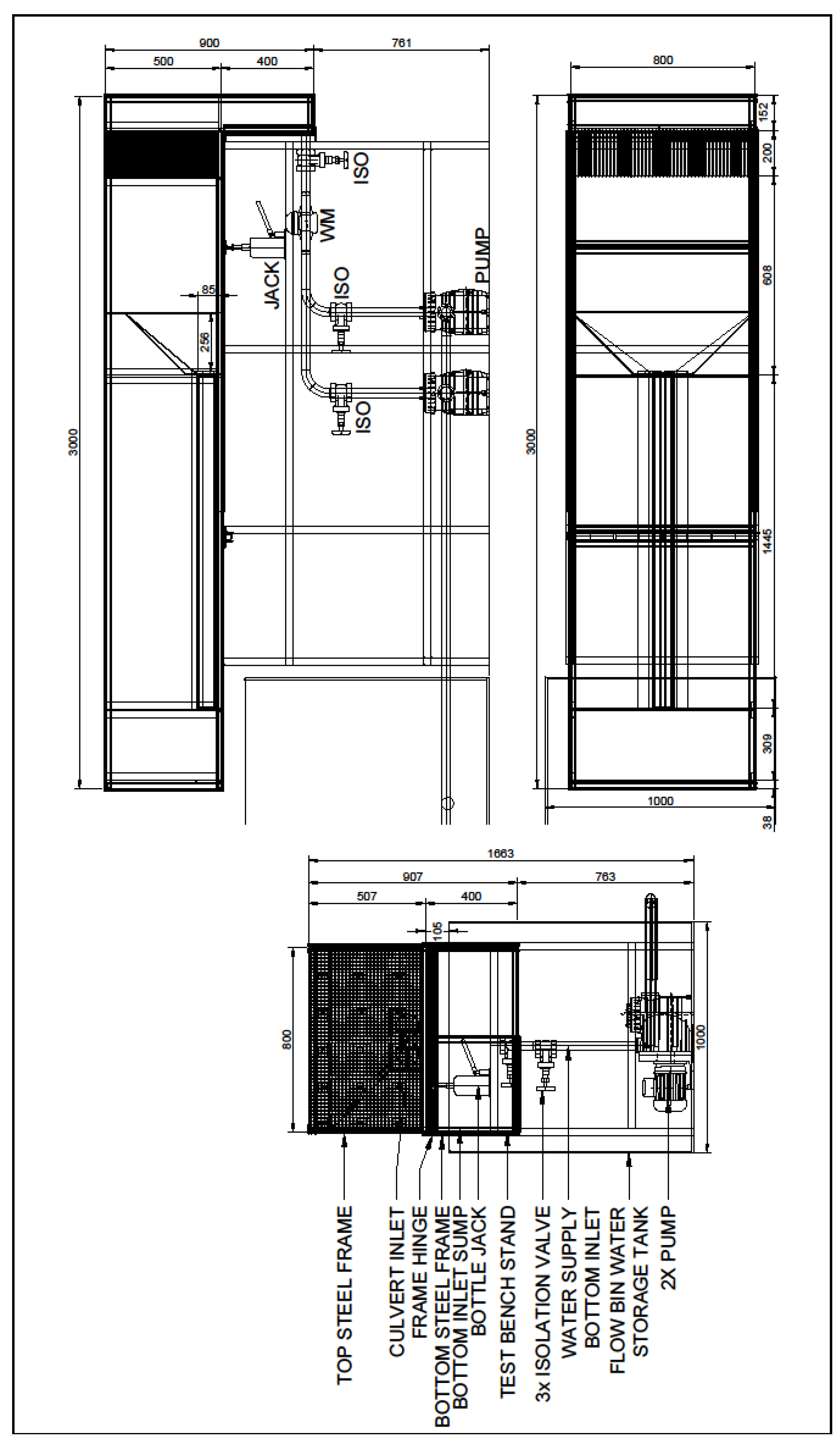
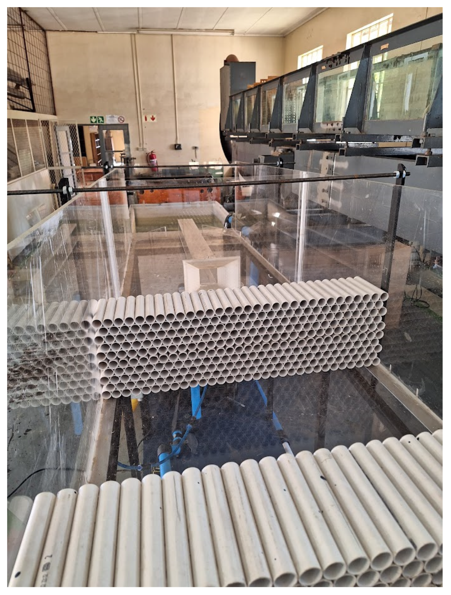
An experimental culvert model was constructed in the Water Laboratory of the University of Pretoria (UP Waterlab). The model consisted of a single-barrel square culvert and three headwall/wingwall (inlet) combinations. The model channel and culvert barrel were constructed out of clear Plexiglass with a thickness of 10 mm. Two of the three culvert inlets were 3D printed. The model frame was hinged on one side and had two hydraulic jacks on the other side to be able to adjust the culvert slope. The model was supplied with two BADU Porpoise 22 1.1 kW pumps, installed in parallel. A mechanical flowmeter was supplied on the upstream side of the model. PVC conduits were cut into 200 mm lengths and then pasted together and installed on the upstream side of the model channel to ensure uniform flow towards the culvert inlet as well as reduce wave action. Additionally, in order to reduce turbulence at the culvert inlet, water entered the model in a sump upstream of the PVC conduits.
Figure 2 shows a schematic flow diagram of the culvert model and
Figure 3 shows a CAD drawing.
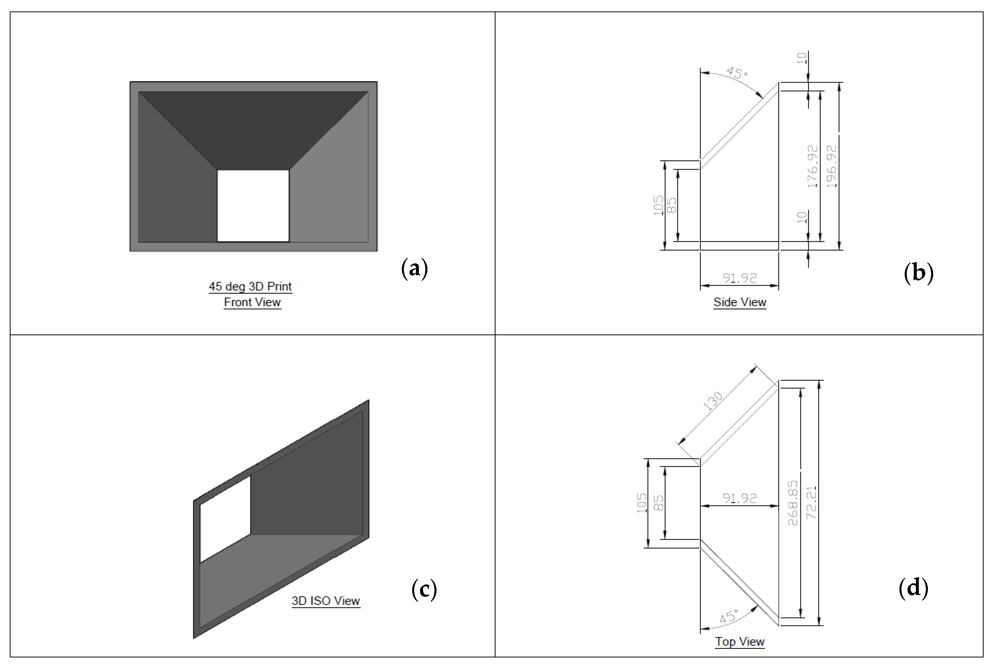
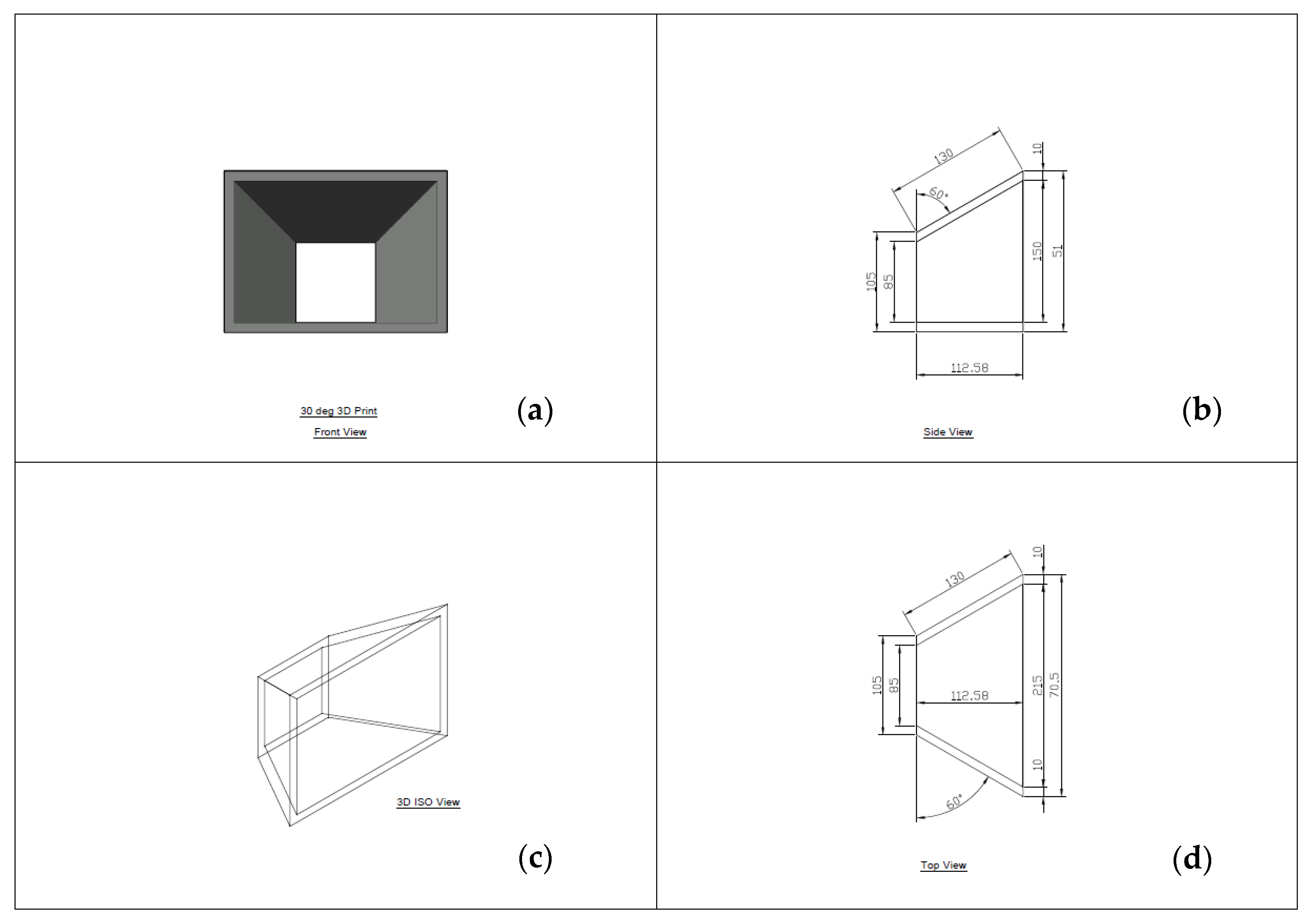
Three angles for the headwall and wingwalls were selected, namely 90 degrees, 45 degrees and 30 degrees. Both the wingwalls and headwalls were positioned at these angles, measured parallel with the inside of the culvert walls, opposite to the direction of flow. Since these configurations for the 45-degree and 30-degree models created complex shapes, these models were 3D printed as mentioned previously. The three headwall/wingwall models were printed so that their inlets could fit inside a collar that was provided on the plexiglass culvert section.
Figure 4 and
Figure 5 show CAD drawings of the 45-degree and 30-degree models, respectively.
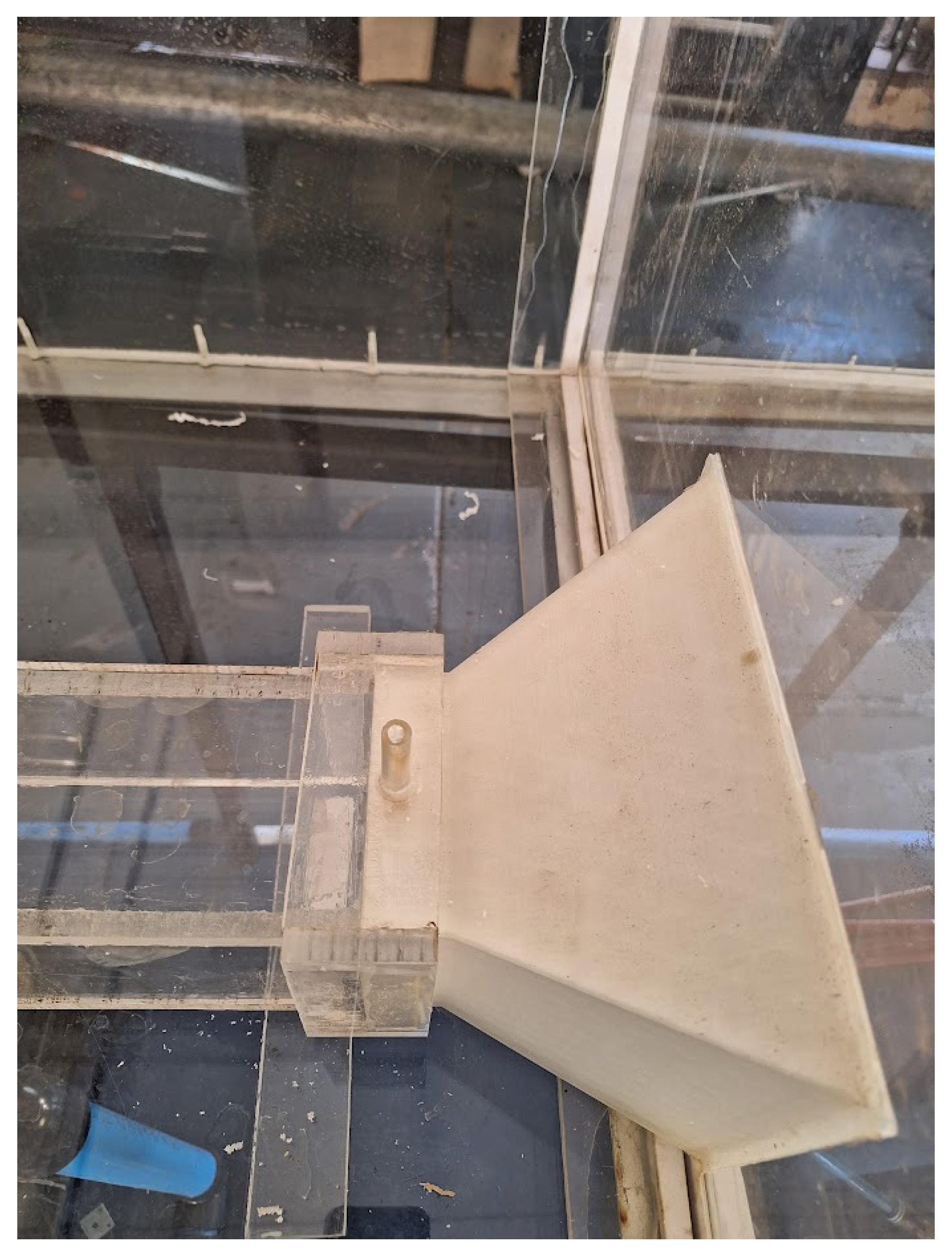
A plastic tube was attached through the bottom of the culvert channel just upstream of the headwall. The purpose of this tube was to be able to take water level measurements without any wave interference. Additionally, a small plexiglass tube was attached through the collar on the culvert section to be able to test the effect of introducing air into the culvert section downstream of the culvert inlet.
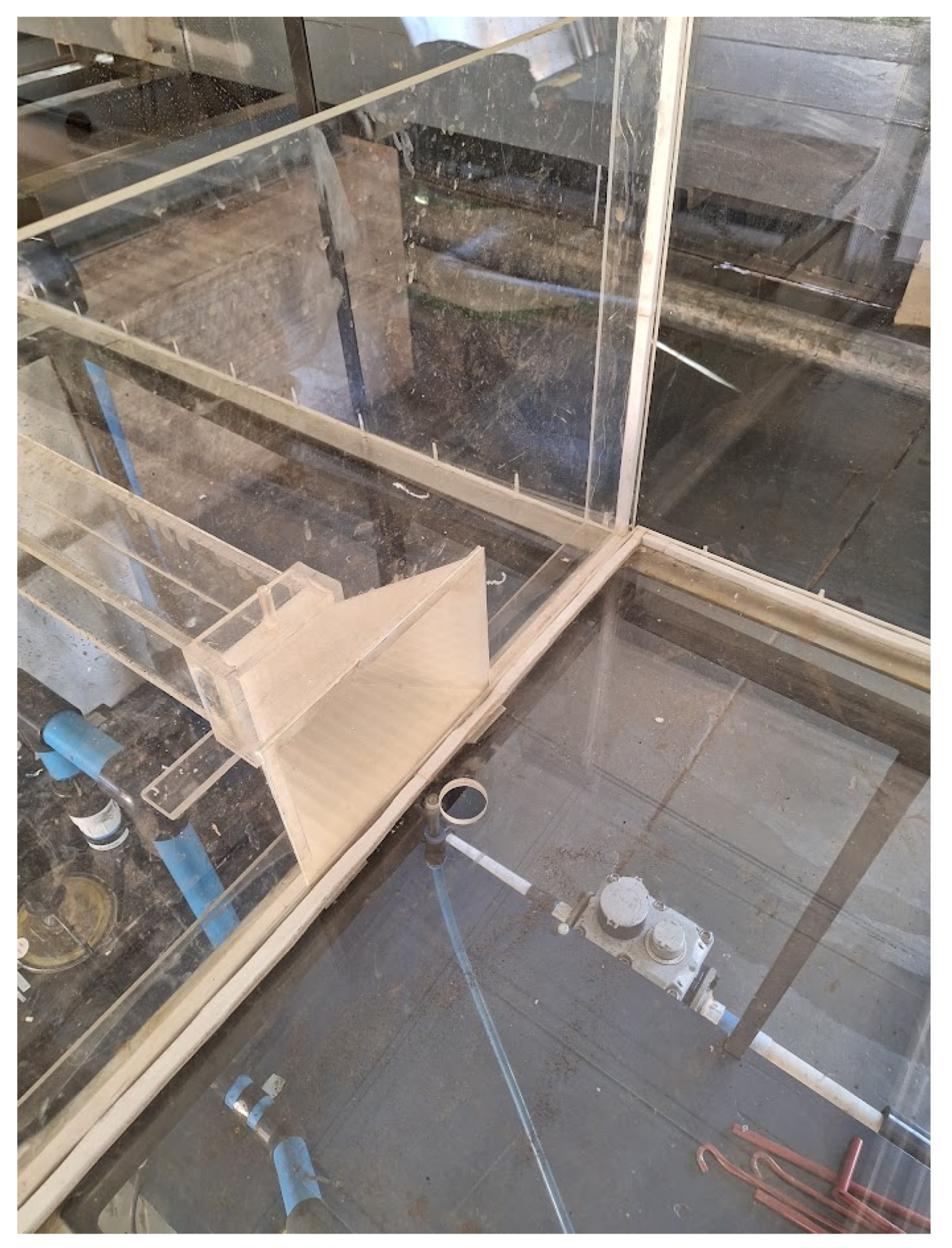
Figure 6 shows the culvert from the downstream side. Note the PVC conduits upstream of the 3D-printed culvert inlet.
Figure 7 shows the culvert from the upstream side. The PVC conduits were stuck together in two parts to provide flexibility in the setup of the model.
Figure 8 shows the same 3D-printed inlet from another angle. Note the attached plastic tube passing through the bottom of the model channel and the mechanical flowmeter.
Figure 9 shows a close-up view of the 3D-printed culvert inlet with the ventilation tube clearly visible.
To carry out the experiments, a headwall model was selected and fixed in place in the channel using silicone sealant to ensure water tightness. The sealant had been allowed to dry for 24 h before water was pumped through the model. Before the experiments were started, the culvert channel was levelled using a spirit level. The pumps were started and switched off again after a short while. The water in the channel was allowed to flow out and settle at the lower edge of the inlet model. This water level was then marked on the measurement tube as the lowest level from which all measurements were taken. The ventilation tube was blocked while inlet conditions were being tested.
The isolation valve downstream of the water meter was used to throttle the flow from the pumps, starting with a very small flow rate. The flow rate was measured by taking measurements from the mechanical flow meter using a stopwatch. At least 7 measurements were taken in this way from which an average flow rate was determined. A specific flow rate was allowed to flow through the model for at least 2 min before the water depth was measured. This was performed to allow the water depth in the model to stabilise. The water depth was measured on the measurement tube. This process was repeated while progressively allowing more water through the isolation valve until the valve was completely open. The same process was then followed while closing the isolation valve progressively.
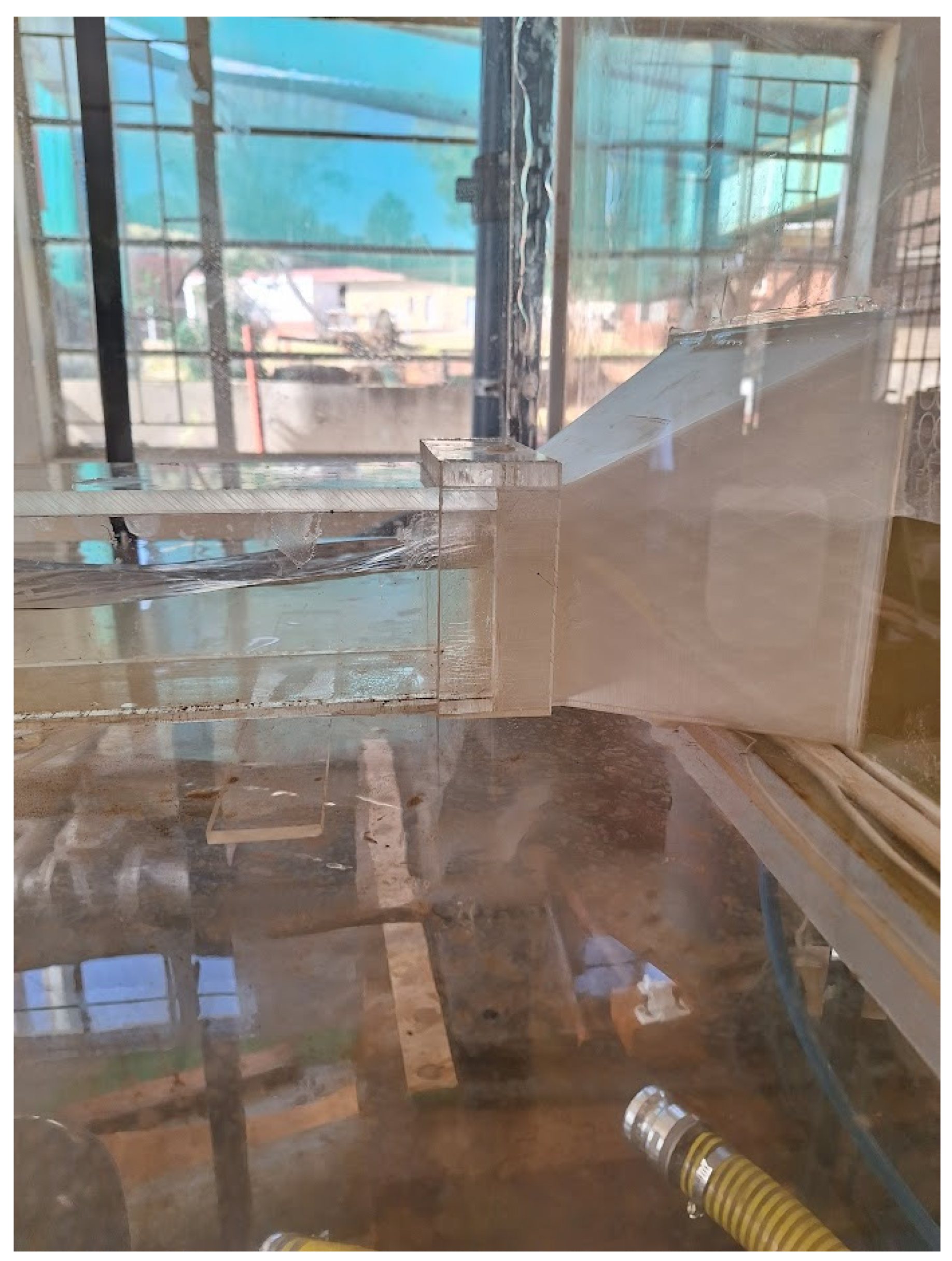
Figure 10 shows the water flowing through the 30-degree headwall.
3. Results
The results for each headwall/wingwall model experiment are discussed in this section.
3.1. 90 Degree Headwall
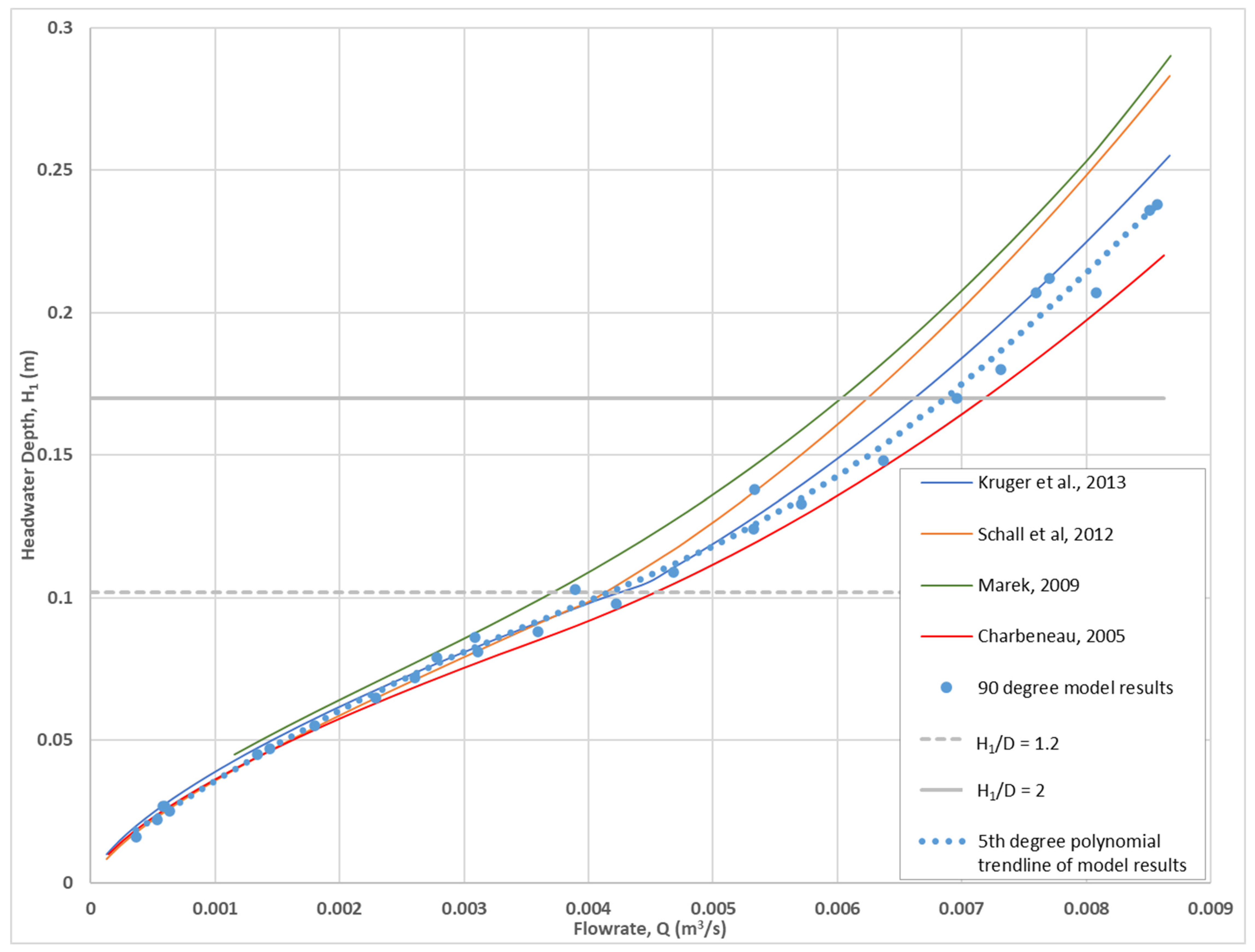
The measured headwater depths were plotted against the average flow rates as measured. A fifth-degree polynomial trendline was generated using the plotted data. The measured data and the trendline are presented in
Figure 11. Also presented on this figure are inlet control performance curves for selected equations, calculated using the dimensions of the 90-degree model.
Figure 11 shows that the measured data tracks the performance curves for selected equations very well and is therefore considered credible. For unsubmerged flow, the results fit the performance curve for Schall et al. [
47] the best. For submerged flow (from about H
1/D > 1.2), the trendline tracks between Kruger et al. [
1] and Charbeneau [
49].
The fifth-degree polynomial trendline based on the measured data was specifically compared to the Kruger et al. [
1] equation and performance curve in order to potentially improve the performance of the equation proposed by Kruger et al. [
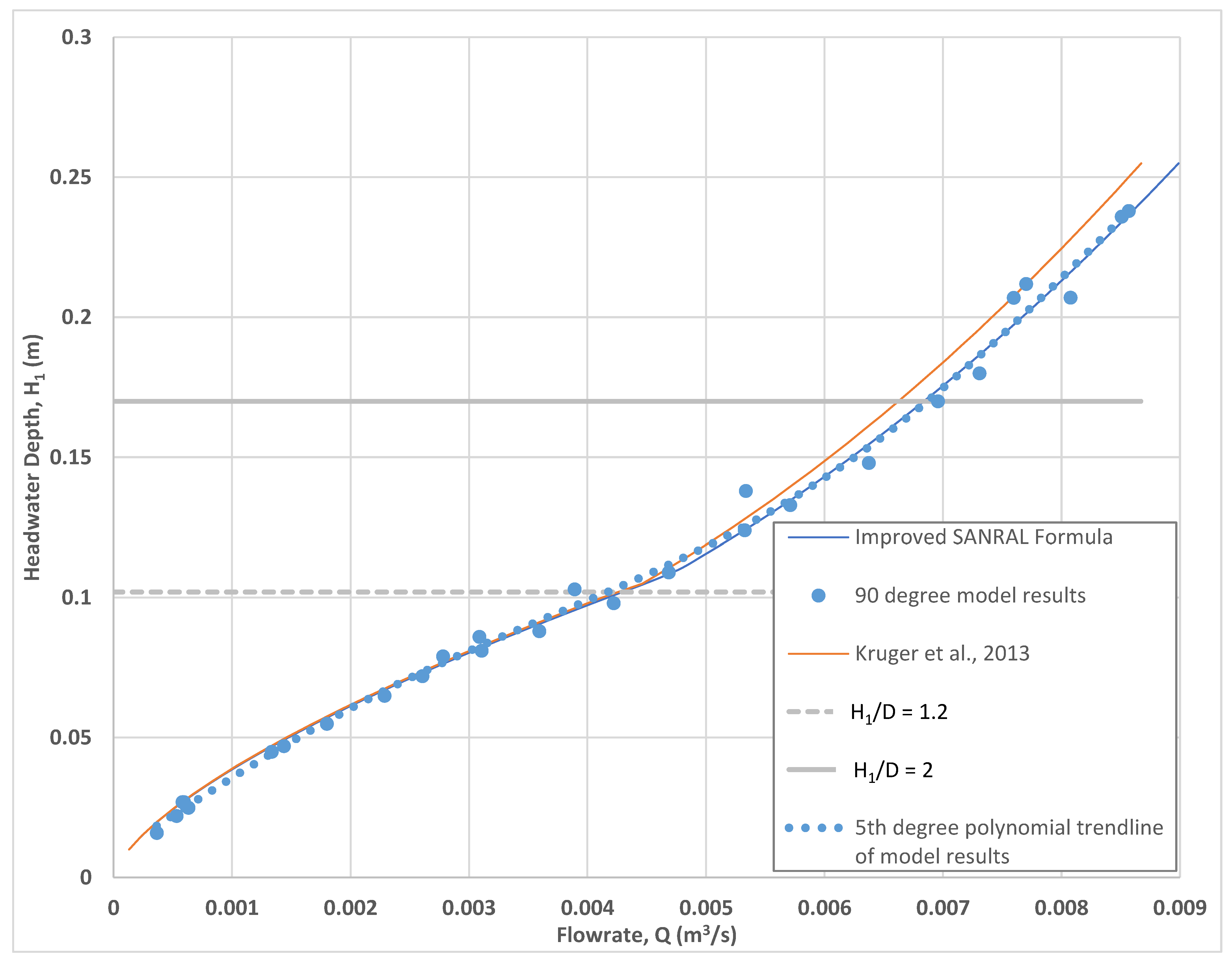
1]. It was found that increasing the Cb factor from 0.9 to 0.91 for square inlets and increasing the Ch factor from 0.6 to 0.625 for square inlets and applying the unsubmerged equation for H
1/D values equal and smaller than 1.235 and applying the submerged equation for values above 1.235 yields a performance curve that approximates the fifth-degree polynomial trendline based on the measured experimental data. This improvement is shown in
Figure 12.
3.2. 45-Degree-Headwall and 30-Degree-Headwall Models
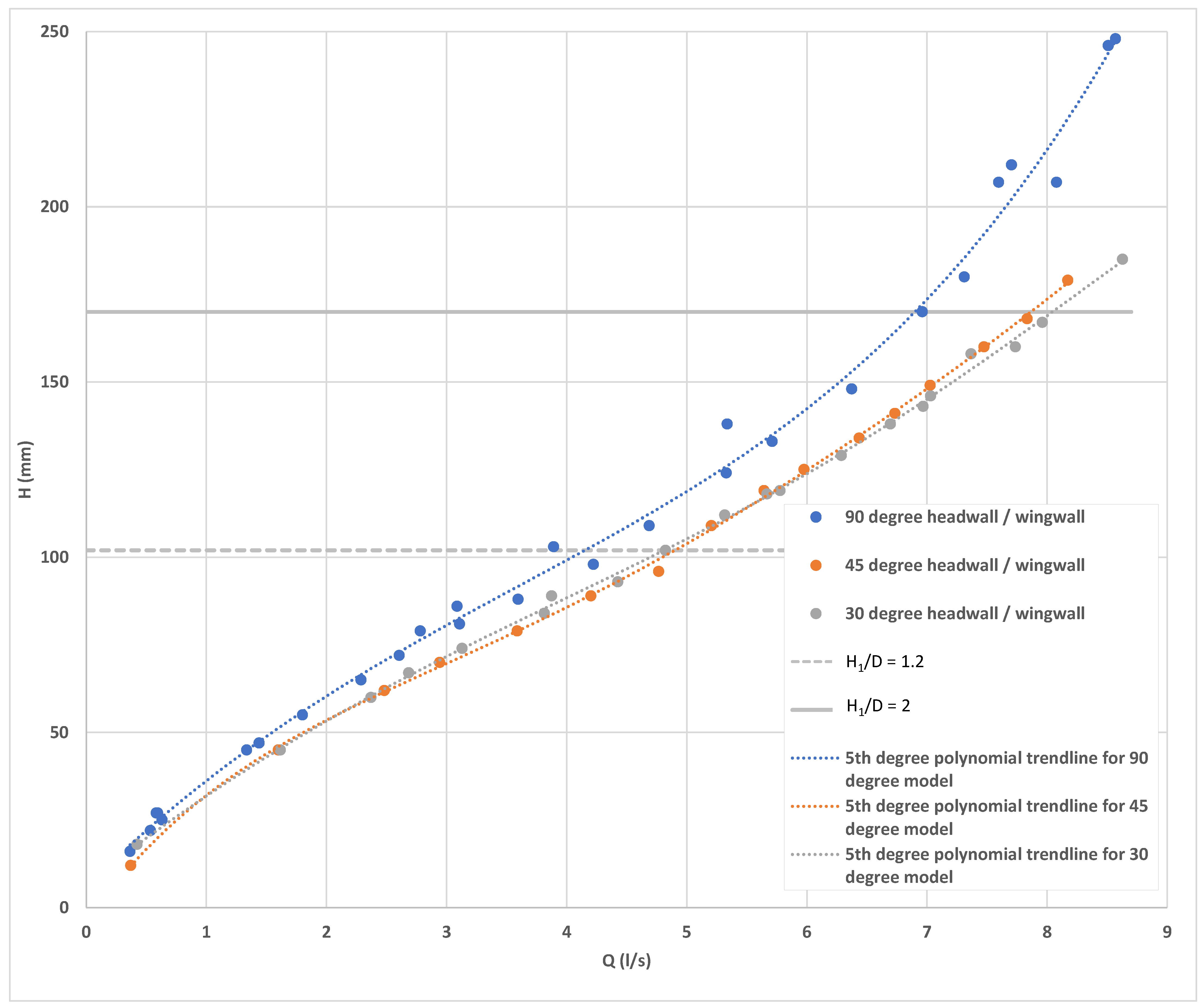
For the 45-degree- and the 30-degree-headwall models, the measured headwater depths were again plotted against the average flow rates as measured. A fifth-degree polynomial trendline was generated for each model by using the plotted data. The measured data and the trendlines were plotted and then compared to the 90-degree model data; the results are presented in
Figure 13.
The reduction in headwater depth for the 30-degree and the 40-degree models compared to the 90-degree model can clearly be seen in
Figure 13 and will be discussed later in this chapter.
The 30-degree and 45-degree models incorporated an angled headwall in addition to the angled wingwalls. It appears that this improvement combination has not been studied in detail before. To determine the impact of the angled headwall, it was decided to compare the results to the fifth-order polynomial formula proposed by Marek [
48], calculated for similar dimensions as the experimental model but using parameters for angled or flared wingwalls as provided in
Table 1:
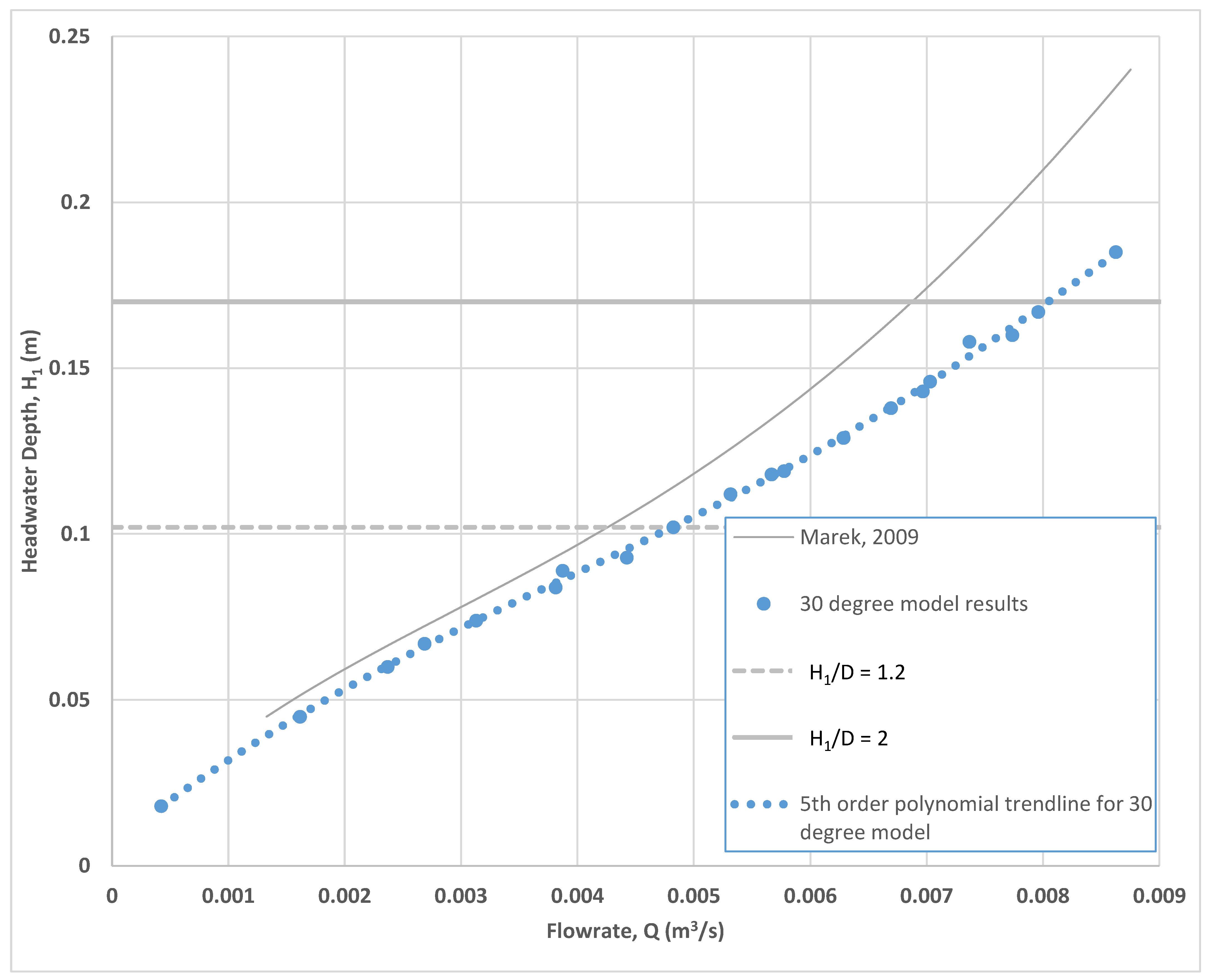
The comparison between the calculated performance curves using Marek [
48] and the modelled data for the 45-degree- and the 30-degree-headwall/wingwall models are presented in
Figure 14 and
Figure 15, respectively.
It was decided to adjust the parameters for the equation proposed by Marek [
48] to fit the modelled results better. In both cases, setting the parameter a = 0 yielded a graph that fit the modelled results very well for flows where H
1 < 0.085 m (or H
1/D < 1), where the angled headwall improvement cannot influence the flow of the water through the culvert. For flows where H
1 > 0.085 m (or H
1/D > 1), a divergence between the Marek [
48] equations and the modelled results can clearly be seen, with the angled headwall improvement clearly resulting in a reduction in headwater depth for similar flows. The results for the 45-degree- and 30-degree-headwall/wingwall models are presented in
Figure 16 and
Figure 17, respectively.
3.3. Inclusion of a Ventilation Device
As discussed previously, a ventilation tube was installed in the culvert barrel, just downstream of the culvert inlets (see
Figure 9). While the experiments were being carried out, the ventilation pipe was blocked so that no air could move freely between the atmosphere and the inside of the culvert barrel via the ventilation tube.
During experiments where the flow rate was great enough to cause the culvert to be submerged sufficiently, and after the relevant readings were taken, the culvert was forced to operate under outlet control conditions by blocking the outlet of the culvert manually and allowing the culvert to fill up and flow full. The downstream blockage was removed, and if the culvert continued to flow full, the blockage in the ventilation pipe was removed after the flow was allowed to stabilise. Under these conditions air would enter the culvert barrel, which would then stop flowing full. The flow regime would therefore return to inlet control conditions within a couple of seconds. It was found that an aeration device (a long PVC tube) that was manually inserted through the inlet into the barrel of the culvert had the same effect. Unfortunately, due to the limitations of the pumps installed in the model, this effect could only be tested at the maximum flow rate of 8.51 l/s on the 90-degree model.
The inclusion of a ventilation device could therefore, under some circumstances, enable culverts flowing under outlet control conditions to return to flow under inlet control conditions, as the entered air reduced the friction that the flow experienced at the top of the culvert. Since the effect of a ventilation device happens downstream of the inlet of a culvert, it does not technically fall within the scope of this research project but could be the subject of future research.
4. Discussion
4.1. Discussion of Modelled Results
It was shown that existing research formulae and graphs compare well with the results of the model study. It was found that the Kruger et al. [
1] formula can be improved as follows:
Increasing Cb from 0.9 to 0.91 for square inlets;
Increasing Ch from 0.6 to 0.625;
Applying the unsubmerged equation for H1/D values equal and smaller than 1.235;
Applying the submerged equation for H1/D values above values of 1.235.
It was found that 30-degree- and 45-degree-angled wingwalls together with a similarly angled headwall greatly improves the performance of a culvert when compared to using square headwalls and wingwalls.
This performance increase is summarised in
Table 2:
Table 2 shows that, even though there is a significant increase in the performance of culverts when angled headwalls and wingwalls are installed (when compared to square inlets), there is not a significant increase in performance between the 30-degree and 45-degree models. This correlates to the work conducted by Marek [
48], where the same parameters were given for the fifth-order polynomial equations for flared wingwalls between 30 degrees and 70 degrees.
Unfortunately, due to the limitations of the models tested, it was not possible to calculate the percentage increase in efficiency that the angled headwall is responsible for compared to angled wingwalls only. This is partly due to the fact that the modelled results for the 90-degree headwall cannot directly be compared to the 90-degree results calculated by Marek [
48]. This increase in efficiency should be the subject for future research. It is recommended that the results of this research be used to develop a CFD (computational fluid dynamics) model that can also be used to calculate this increase in efficiency.
Importantly, it was also found that the angled headwall improves the performance of the culverts significantly more than just the improvement that can be expected with angled wingwalls only (see
Figure 16 and
Figure 17). Of course, this improvement is only realised at flow depths of more than H
1/D = 1.
Furthermore, it was found that the inclusion of a ventilation device could, under some circumstances, force culverts flowing under outlet control conditions to flow under inlet control conditions, should it be preferred. The mechanism, quantum and conditions under which these improvements could be realised should be the subject of future research.
4.2. Practical Implementation of Modelled Results
This section discusses the practical implementation of the modelled results.
Increasing the hydraulic performance of culverts can be beneficial during the design of new culverts and when a need exists to retrofit an existing culvert. Each of these use-cases will be discussed below.
4.2.1. Design of New Culverts
When designing a new, unimproved culvert using standard design methodologies, a designer may find that the design flow rate may be equal or slightly less than the calculated hydraulic capacity of a selected precast box culvert with standard dimensions. Under these circumstances, the designer will often choose a conservative approach by selecting a standard precast box culvert with larger dimensions or, if this is not possible, by specifying that a second box culvert be installed to operate in parallel to the first one. Both of these approaches will result in an over-designed culvert system with significant additional cost to the project. The results from the experimental models undertaken as part of this research should give designers comfort that, with some improvements to a culvert’s inlet characteristics, such as the inclusion of angled headwall and wingwalls, a conservative approach is still possible without resulting in an over-designed culvert.
This research has shown that designing a culvert with 30- or 45-degree-angled wingwalls and headwall can provide an additional hydraulic capacity of between 16% and 18% for H1/D = 1.2. These improvements can therefore also result in a culvert being specified, even if the design flow rate is 16–18% more than the calculated hydraulic capacity of such a culvert when designed using standard design methodologies.
Structurally, the proposed angled headwall/wingwall element has a distinct advantage over a traditional wingwall and apron slab combination as the concrete and rebar can be rationally designed and specified, unlike in heavy cantilever wingwalls.
4.2.2. Retrofitting of Existing Culverts
As mentioned before, the South African National Roads Agency (SOC) Ltd. (SANRAL) is increasingly incorporating provincial roads into its national road network to meet the medium- to long-term developmental needs of South Africa. In many instances, the roads being incorporated do not meet the design criteria for the class of road as described in the SANRAL Drainage Manual [
1], as the roads were not necessarily built to the same criteria. Of particular concern is that a road’s classification (after incorporation) may require its drainage culverts to convey a design flood with a higher return period than the one it was originally designed and constructed for.
In addition to this, projections show that in South Africa, climate change may cause a tendency towards an increase in intensity of rainfall or extreme events (Mambo et al. [
2]). Such extreme rainfall events may, over time, cause the original design capacities of installed culverts to become insufficient. If improvements can be made to existing culverts in situ to increase their capacities, it may negate the need for expensive culvert replacements or for additional culverts to be installed in parallel. In the case of existing culverts, the cost and inconvenience of closing a road to upgrade the capacity of a culvert also needs to be taken into account.
If it is determined that an existing culvert’s capacity could be increased sufficiently by retrofitting it with the proposed angled headwall/wingwall improvement, a precast element can easily be prepared and connected to the existing culvert with MBT couplers.
The angled headwall/wingwall elements will result in widening the culvert crossing. This additional space on one side of the culvert can be used to accommodate walkways for pedestrian traffic as an added benefit.
Manufacturers of precast culverts should be encouraged to also manufacture precast 30-degree- and 45-degree-headwall/wingwall elements.
4.2.3. Installation of Ventilation Devices
As discussed previously, a ventilation device could cause the flow through some culverts to flow under inlet control conditions where it would otherwise have flowed under outlet control conditions. This could be a benefit that a designer may wish to utilise.
A ventilation device could be constructed into a new culvert when it is built by connecting the culvert, just downstream of the inlet, to the roadway above it with a pipe. A PVC pipe with a diameter of 160 mm ND or smaller could be installed through a hole in the top of the culvert. The pipe can be grouted into the hole in the culvert. The inlet of the ventilation device on the roadway should be equipped with a grid cover to prevent debris from getting stuck in the inlet. Alternatively, a flexible hose could be attached to the culvert with brackets, originating from the inside of the culvert, just downstream of the inlet, and then going through the inlet and up the headwall. Such a retrofit, although easy to install, may impede the flow through the culvert to some degree and will need careful consideration.
As discussed previously, the installation of a ventilation device has shown an effect in this experimental model, but the extent of the effect and the conditions under which a benefit may be realised should be the subject of future research. Be as it may, a ventilation device can be installed relatively easily and cheaply in new culvert installations without any known disadvantage. A ventilation device could even be incorporated into the road drainage system.
4.2.4. Cost Comparison
Unfortunately, no direct trend could be identified when comparing barrel size to cost savings between traditional wingwall and apron design culvert inlets and the proposed angled headwall/wingwall design using the actual costs for selected SANRAL projects currently being implemented in South Africa. This is due to the individual site conditions having played a role in the design of the culverts. What is clear though, is that there may be no real cost saving when considering the two different culvert inlet types. More data on existing projects may be able to reveal a clearer trend in this regard.
As mentioned previously, the real cost saving that could be expected when installing an angled headwall/wingwall combination on an existing culvert is that the proven increase in flow through the culvert may now allow for the effective drainage of a design flood with a larger return period (for example from a 1:10 to a 1:20 year flood), negating the need to install a larger culvert or additional culverts in parallel, with activities associated with such a project, including:
5. Conclusions
The design of culverts is a staple of engineering hydraulics courses all over the world, yet the standard methodologies that are used to design them do not always consider the benefits that could be achieved by optimising the inlet characteristics for culverts flowing under inlet control conditions. This fact, together with an overly conservative approach by some designers, has caused many culverts to be overdesigned and more expensive than they need to be. Recently, however, it seems that there has been renewed interest in this field, which is encouraging.
The South African National Roads Agency (SOC) Ltd. (SANRAL) is incorporating many provincial roads into its national road network. These roads were not necessarily constructed to meet the design criteria for the class of road as described in the SANRAL Drainage Manual [
1]. In some cases, a road’s classification (after incorporation) may require its drainage culverts to convey a design flood with a higher return period than the one it was originally designed and constructed for.
An added concern is that, according to projections, climate change may cause a tendency towards an increase in the intensity of rainfall or extreme events (Mambo et al. [
2]) in South Africa, which may cause the original design capacities of the installed culverts to become insufficient.
These factors can, of course, be considered when a new culvert is being planned and culverts can in such a case be designed to safely convey the required design flow. A bigger challenge, however, is increasing the capacities of existing culverts. Traditionally, this would require that a road be closed and either the existing culvert be removed and replaced with a new culvert of larger dimensions or additional culverts be installed in parallel. Many times, the cost and inconvenience of closing or redirecting a road to upgrade the capacity of a culvert is prohibitive. If improvements can be made to existing culverts in situ to increase their capacities, it may negate the need for expensive culvert replacements projects.
This research looked at the benefit of adding not only angled wingwalls but also an angled headwall to the inlets of culverts to increase their hydraulic performance, a combination that has not yet been the subject of much research. The installation of ventilation devices was also considered to introduce air into a culvert that may be flowing under outlet control conditions. The research was carried out by simulating flows through a culvert using an experimental model that was constructed in the University of Pretoria Water Laboratory.
The model consisted of a single-barrel square culvert and three headwall/wingwall (inlet) combinations (90 degrees, 45 degrees and 30 degrees). The 45-degree- and 30-degree-headwall/wingwall models were 3D printed.
The results of the experimental model for the 90-degree model compared favourably with previous research and established formulae. For a square headwall, various improvements are proposed for the SANRAL 2013 coefficients for flow under inlet control conditions. It was found that increasing the Cb factor from 0.9 to 0.91 for square inlets and increasing the Ch factor from 0.6 to 0.625 for square inlets and applying the unsubmerged equation for H1/D values equal and smaller than 1.235 and applying the submerged equation for values above 1.235 yields a performance curve that approximates the fifth-degree polynomial trendline based on the measured experimental data.
The 45-degree and 30-degree models compared favourably with established fifth-order polynomial equations and coefficients up to H1/D of = 1 and showed an improvement in flow rates for the same headwater above this point. The performance of culverts, operating under inlet control conditions, can therefore be improved by adding wingwall/headwall combinations. It was found that the 45-degree and 30-degree models showed increases in performance of 18% and 16%, respectively, for H1/D = 1.2 and 13% and 16%, respectively, for H1/D = 2, when compared to the results for the 90-degree model. This increase in performance can be of great benefit to designers of new culverts and when retrofitting existing culverts.
It was also found that a ventilation device caused the flow to change from outlet control to inlet control in the experimental model. The addition of a ventilation device to culverts could therefore assist with changing the flow control condition from outlet control to inlet control should this be required by the designer. This novel design element requires further research.
This research found that precast headwall/wingwall elements can easily be connected to existing culverts if an increase in hydraulic performance is required. Not only is this a quick and relatively cost-effective solution but the added road width can be utilised for pedestrian traffic.
For new and existing culverts, adding a ventilation device to the culvert may be a cost-effective method of ensuring that the culvert flows under inlet control conditions in certain cases. A ventilation device can also be incorporated into the road’s drainage system.
Structurally, the proposed angled headwall/wingwall element has a distinct advantage over a traditional wingwall and apron slab combination as the concrete and rebar can be rationally designed and specified, unlike in heavy cantilever wingwalls. It was found, however, that this benefit may not necessarily translate into a cost saving. Real cost savings can, however, be achieved when negating the need to close or divert a road, excavating and removing the existing culvert and replacing it with a culvert of a larger capacity or installing additional culverts in parallel and then reinstating the road with the relevant layer works and surface.
This study has identified the need for further research to be carried out as follows:
A detailed study into the potential benefits of installing a ventilation device in culverts;
The increase in efficiency of an angled/headwall inlet improvement over angled wingwalls only;
A computational fluid dynamics model should be developed, incorporating this study, to aid in future culvert flow calculations.
In conclusion, this research underscores the feasibility and benefits of enhancing culvert hydraulic performance through innovative design modifications. The proposed solutions offer not only improved functionality but also sustainable and cost-effective alternatives to the conventional approach of closing roads for extensive culvert replacements. As infrastructure challenges persist, these findings contribute valuable insights to the evolving field of hydraulic engineering, promoting resilience and adaptability in the face of changing environmental and infrastructural demands.


