Article

Two-Dimensional Modelling for Dam Break Analysis and Flood Hazard Mapping: A Case Study of Papadia Dam, Northern Greece

by
Christos Mattas
1,
Dimitris Karpouzos
2,*,
Pantazis Georgiou
2 and
Theodoros Tsapanos
3
1
Department of Structural, Historical and Applied Geology, School of Geology, Aristotle University of Thessaloniki, 54124 Thessaloniki, Greece
2
Department of Hydraulics, Soil Science and Agricultural Engineering, School of Agriculture, Aristotle University of Thessaloniki, 54124 Thessaloniki, Greece
3
Department of Geophysics, School of Geology, Aristotle University of Thessaloniki, 54124 Thessaloniki, Greece
*
Author to whom correspondence should be addressed.
Water 2023, 15(5), 994; https://doi.org/10.3390/w15050994
Submission received: 23 January 2023 / Revised: 1 March 2023 / Accepted: 2 March 2023 / Published: 6 March 2023
(This article belongs to the Special Issue Flood Risk and Response Management)

Abstract

:
Dams are expensive technical constructions that ensure food production, sustain farmers’ income, and cover a large percentage of urban water supply demands. However, the threat of a dam break flood, which can be extremely dangerous for the local society, should be taken into account, and proactive mitigation measures should be planned. Towards this direction, dam break modelling and flood hazard assessment are essential for developing flood crisis management and evacuation plans. In this study, a hypothetical case of failure of the Papadia dam in the Florina Regional Unit in northern Greece is examined. Two scenarios of failure were considered: overtopping and piping. A two-dimensional numerical model for the two failure scenarios was used to simulate the dam break process and flood wave routing using HEC-RAS software. A sensitivity analysis of the mesh size and breach parameters was performed to better understand their impact on the critical outputs of the simulation model. Flood hazard maps were produced in GIS environment based on water depth and velocity criteria. Furthermore, two classification approaches were adopted to assess the flood hazard using the product of water depth and velocity. The results showed that the extent of the inundated area could affect most of the study area and could cause severe damage to agricultural activities.

1. Introduction

Dams are designed to serve various purposes such as irrigation, fresh water supply, industrial water supply, flood control and electrical power generation [1]. Earthen dams are among the most widely constructed dams due to their lower cost and better suitability for foundation in different geological and geomorphological conditions, compared to other dam types. According to the Greek Committee on Large Dams [2], there are 135 dams operating in the Greek territory (most of them are earthen), following the population growth, increased irrigation demands, need for power generation and improvement of the living standards of Greek society over the last decades. However, earthen dams are more susceptible to failure, as they are less rigid [3]. There are many incidents worldwide where natural hazards have caused damage to natural environments and human constructions. Many floods have caused economic losses, infrastructure damage and loss of human life [4]. Increased frequency of flood events [5,6] has led to a global awareness of flood risk management. Extreme rainfall events, resulting from climate change, contribute to flooding phenomena [7]. The risk of a dam failure due to flooding phenomena could cause devastating disasters that affect human safety, ecological quality and the landscape [8,9,10,11]. The created flood wave changes active sediment transport and morphology of the downstream area [12]. The small predictability of such events [13] along with the magnitude of the catastrophic impacts, especially in urban and agricultural areas, classify floods created by human construction failures as one of the top hazard risks. In particular, Greece is vulnerable to flooding phenomena due to the varying geomorphological, physiographic and climatic conditions. There have been 26 major floods recorded during the period 1900–2017, which caused 113 human lives lost, had an impact on the life of 23,000 people and a total economic cost of USD 2.0 billion [14].
Most dam failures have been recorded on earthen dams following extreme rainfall events that resulted in heavy floods [15]. The main mechanisms that cause dam failure are overtopping and piping. Overtopping failures result from the erosive action of water on the embankment due to the uncontrolled flow of water over, around, and adjacent to the dam. Inappropriate design of the spillway and insufficient capacity of the reservoir for extreme inflows can cause overtopping [16]. Spillways, downstream slopes and foundations are the potential locations at risk for overtopping failure [17]. Piping failure occurs when seepage through a dam is not properly filtered and soil particles continue to progress and form sinkholes in the dam (https://damsafety.org/dam-failures, accessed on 5 December 2022), and the entire dam section is at potential risk. An orifice pressure flow equation simulates the water flow through the dam during a piping failure breach. The breach will start as a tiny rectangle (or trapezoidal) hole and grow until the piping hole is large enough. A mass caving of material will happen if the piping hole is large enough and the weight of the material above the hole is too much to support. This will hasten the breaching process and will cause a significant increase in the outflow via the breach. The hydraulics of the flow also change at this point, moving from a pressure/orifice type flow to an open-air weir type flow. The breach may continue to widen and cut down until it reaches the natural channel bed, depending on the amount of water behind the dam.
Data derived from the International Commission on Large dams reveal that about one-third of dam failures is caused by overtopping, the second-third is caused by piping, and the remaining third of failures is due to other factors (settlements or liquefaction) [18].
The importance of a dam failure modelling and flood wave hydraulic simulation is necessary for decisionmakers and authorities in building emergency response evacuation plans, long-term land use plans and design of mitigation plans for reducing risk of human safety and property damage [19]. Different methodologies and indices have been proposed for hazard mapping of inundated areas regarding buildings/infrastructure damage and people’s safety, based on the results of the hydrodynamic simulation of floods. European Directive 2007/60/EC (assessment and management of flood risks) resulted in the creation of hazard maps in all European Union countries. In Greece, related maps are available by the Special Secretariat of Water on the web page of the Hellenic Ministry of Environment and Energy. The product of velocity times flood water depth is involved in most of them and has been used by many researchers and institutions [20,21,22,23].
There are many models or software for analysing dam failure and to investigate flood wave propagation downstream of the dam. One of the most commonly used models is the Hydrologic Engineering Centre—River Analysis System (HEC-RAS) model developed by the Hydrologic Engineering Centre of the United States Army Corps of Engineers in 1981 and has been improved, enriched and updated since then. It is employed for dam breach parameters calculation, inundation mapping and hydraulic simulation of the flood wave, which is vital in dam failure studies and for the design of precautionary or emergency plans. The HEC-RAS model has been widely used as the simulation tool for dam break analysis due to overtopping or piping failure [24,25,26,27,28,29,30].
Dam breaks and resulting floods constitute complex phenomena with many uncertainties that can cause unpredicted damage to downstream areas and threaten the lives of the local population. Therefore, a main research issue of a dam break analysis is to develop an integrated approach for flood wave propagation and flood hazard visualization and estimation.
The objective of this study is to investigate hypothetical scenarios of both overtopping and piping failures for the Papadia dam in Florina Prefecture, Greece, and to assess the flood hazard. The assumption that the hypothetical failure was caused by the probable maximum flood (PMF) was adopted for the overtopping scenario. A 2D unsteady flow HEC-RAS model was employed to represent the geometry of the dam, to estimate dam breach characteristics and to perform hydraulic calculations [31]. A digital elevation model (DEM) is used as a base for the floodplain area. The simulation procedure based on hydrological modelling is followed by a sensitivity analysis as to provide better knowledge of the impact of model parameters on the critical model outputs [32]. A flood hazard procedure is implemented by the coupling of GIS and RAS-Mapper using different classification approaches based on maximum water depth, maximum water velocity and the product of water depth times velocity. The depth–velocity product is usually considered as a critical variable for damage to a collapse of buildings and human instability. Detailed flood hazard maps based on the above criteria are produced, and the affected areas are identified. The current study provides critical information for peak discharge on the boundary conditions and flood travel time and damaged land use categories. The timely receipt of information produced by the proposed methodological framework could be vital in preventing human loss.

2. Study Area—Dam Characteristics

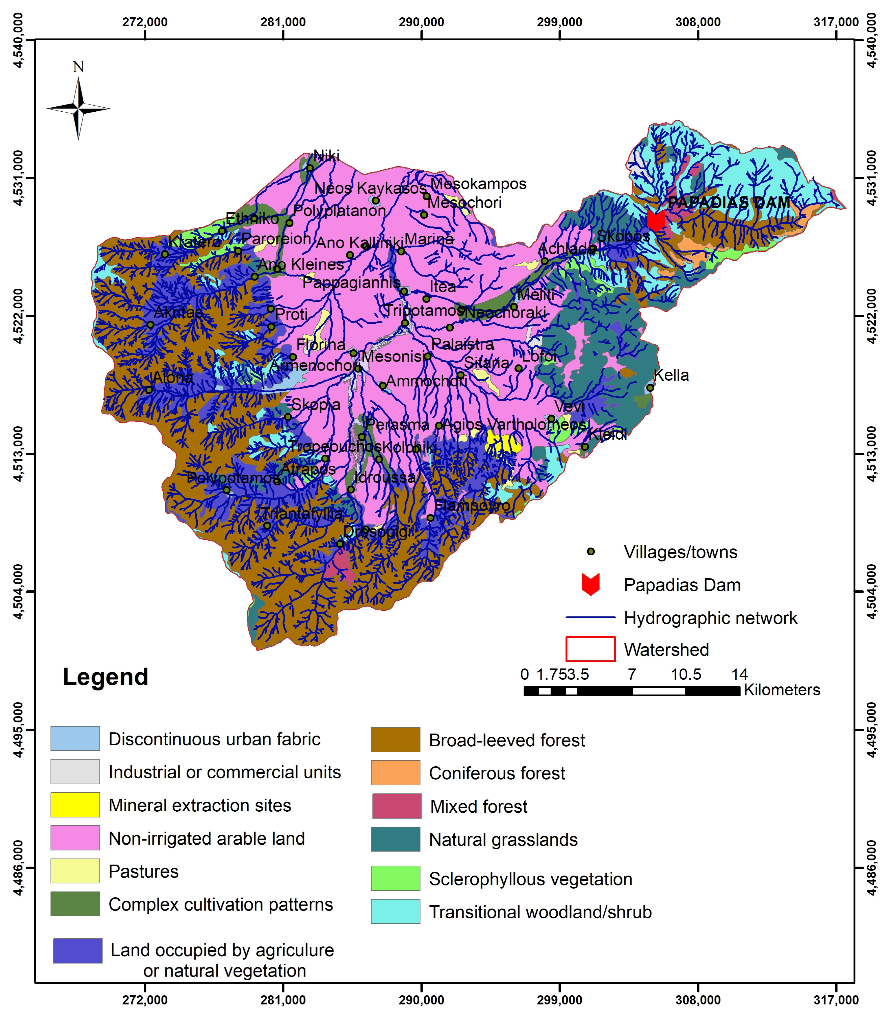
The catchment upstream of the Papadia dam is developed within the Florina basin boundaries, as is depicted in Figure 1. The Florina basin is located in the West Macedonia region in Greece, covering 863 km2. The mean precipitation in the Florina basin is 870 mm, and the mean temperature is 11.3 °C. The Florina basin belongs to the Pelagonian geotectonic zone. The basin’s mountainous area is occupied by carbonate and crystalline rocks [33]. The lower parts consist of Neogene and Quaternary sediments. The Quaternary sediments are alluvial deposits and consist of alternations of sands, gravels, conglomerates, and clays, while the Neogene sediments consist of marls, sandstone, sands, and marly limestone. The length of maximum thalweg is equal to 16.5 km. The vast majority of the geological formations in the area are characterized as impermeable to moderately permeable, regarding the hydraulic conductivity [34], favouring the creation of a dense extended hydrographic network. The Papadia basin upstream of the dam covers an area of 77 km2. The elevation ranges from 871 to 2523 m a.s.l., and the mean elevation is 1540 m a.s.l. The mean slope is 33.5%. According to Corine land cover (2018), the dam upstream basin is occupied mainly by forest land. The Florina basin in general is occupied by forest and agricultural land, as is depicted in Figure 2 and Table 1.
The Papadia dam is used for the cooling of the Meliti Thermal Power Station after its construction in 2008 by the Public Power Corporation of Greece. It is a rock fill dam with an impervious clay core (Figure 3) and has a volume equal to 3.5 × 10⁶ m3. The main technical characteristics of the Papadia dam and its spillway are shown in Table 2.

3. Model Elaboration

HEC-RAS can perform numerical computations of steady or unsteady flow conditions in one-dimensional (1D) or two-dimensional (2D) models. One-dimensional model computations are performed using Saint Venant equations at selected cross-sections created along the riverbed following flow direction and are used in certain cases such as in channel planning [35,36]. In the 2D model, a finite-element mesh is created that solves the Saint Venant equations in an area over the river channel and the floodplain [37]. The use of a 2D modelling approach is adopted in this study for more accurate or realistic results [38,39] since it can simulate complex flow conditions and is able to simulate floodplain inundation and river hydraulics.
The dam failure process and flood wave hydrodynamic simulation using a 2D HEC RAS model (v.5.07) [37] requires the following type of data as input: (a) digital elevation model (DEM) of the area, (b) land use maps and the Manning roughness coefficient, (c) 2D grid (study area), (d) dam reservoir geometry, (e) dam reservoir 2D flow area connection (dam), (f) geometry of the dam, (g) breach structure geometry and characteristics, (h) upstream boundary conditions (flood hydrograph for the case of overtopping) and (i) downstream boundary conditions (normal depth).
Concerning model set up, the reservoir geometry is represented by an elevation-storage volume diagram. The reservoir is connected to the downstream area via the dam, which is modelled as a weir/embankment structure type in the HEC-RAS environment. After collecting and verifying data, the modelling process is conducted in two stages. First, the dam failure mechanism (overtopping/piping) is determined, and the breach geometry is estimated. Precipitation data were used to calculate probable maximum precipitation (PMP), and the produced probable maximum flood (PMF) is used as an input to the model. In the second stage, the outflow hydrograph is estimated, and hydrodynamic simulation of flood wave over time is implemented. Finally, flood water depth and velocity maps of the inundated areas are produced.
Concerning the overtopping failure, the following assumptions were adopted: (a) the water surface in the dam reservoir at the beginning of the failure is at the elevation of the dam crest, and at the same time, the inflow in the storage area is equal to the peak of the PMF; (b) the spillway is blocked by tree trunks or other material; (c) the water from the reservoir flows over the dam crest at the beginning of the simulation (t = 0) and erosion channel on the dam body starts to immediately develop; and (d) the channel is eroded and widened over time until it reaches its estimated final dimensions—the water passes through the channel and over the dam body. Respectively, for the piping failure, it is considered that: (a) the water surface in the dam reservoir at the beginning of the failure is at the elevation of the dam crest; (b) at the beginning of the simulation (t = 0), a small hole occurs at a specific elevation (Hp) of the dam body; this elevation is equal to the final bottom elevation of the dam breach structure; (c) an average daily discharge (that is not related to flooding conditions) is set as an inflow; and (d) breach final bottom elevation was selected for the elevation that produces the highest peak of the outflow hydrograph.
The methodological flow diagram used in this study for the dam break and flood hazard assessment is presented in Figure 4.

3.1. Digital Data

The digital elevation model (DEM) was obtained by the Hellenic Military Geographical Service (HMGS). The spatial resolution is 30 m after digitization of contours (20 m intervals) of the topographic diagrams (scale 1:5000). The Geographic Coordinate System is GCS_GGRS_1987 (Greek Grid). The digital land cover map for the area was derived from CORINE Land Cover Inventory (latest update 2018) available on https://land.copernicus.eu/pan-european/corine-land-cover, 26 November 2022 (Figure 2). The 2D grid flow and storage area were digitized based on the DEM, satellite images (ArcWorld Images) and field observations.

3.2. Breach Parameters

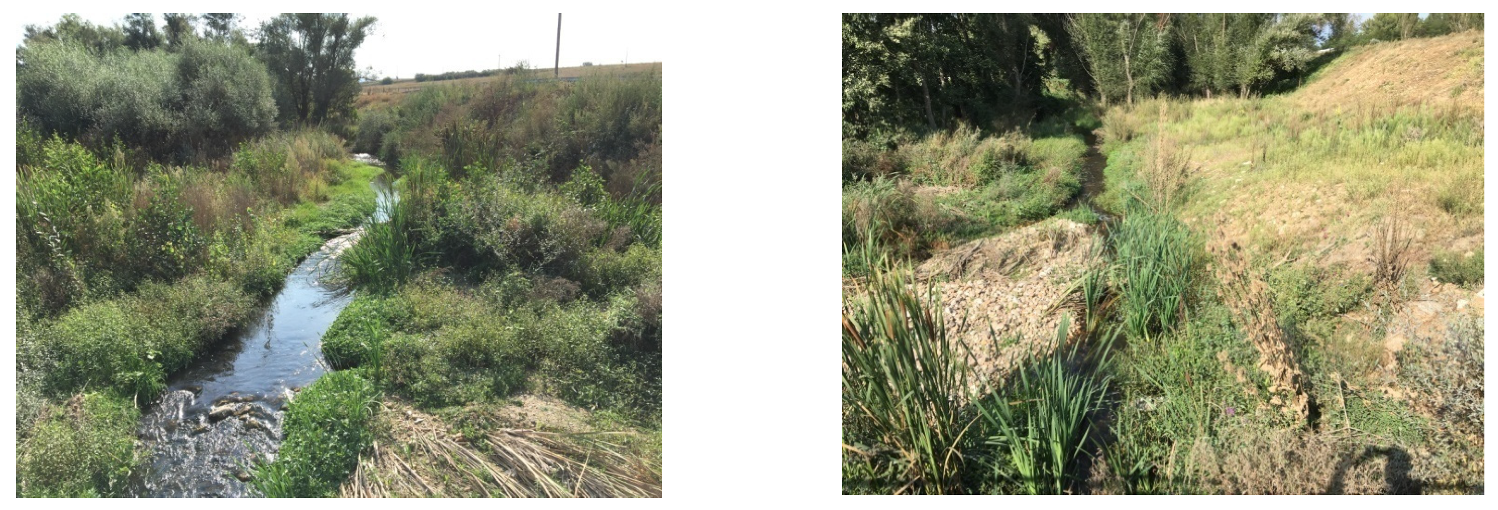
For dam break analysis caused by a flooding phenomenon, empirical regression equations for the estimation of breach parameters have been proposed in the literature and are used worldwide [18,40,41,42,43]. The breach parameters estimation is based on both unbiased and biased data. Unbiased data are the dam height, the material used in dam construction and the reservoir volume. Biased data include the initial water surface in the reservoir, breach bottom elevation, side slope of the breach, flow coefficient over the breach and Manning roughness coefficient. The values of these data are derived based on the examined scenario conditions, the failure mechanism, data collection from previous studies and field observations. The importance of the fieldwork to gain knowledge about the studied area is essential in such studies. The Manning roughness coefficient for the flow area was based on the land cover maps and field observations. The value of the Manning coefficient equal to 0.035, corresponds to natural minor streams that are clean, straight, without rifts or deep pools, and with stones and weeds as suggested by Chow [44]. Indicative photos from the field survey in the area are provided in Figure 5.
According to Figure 2, the vast majority of the study area close to the main channel riverbed is covered by agricultural land. Pastures, discontinuous urban fabric, forests along with sclerophyllous vegetation and woodland cover a small percentage. Most references suggest values that range from 0.03 to 0.04 regarding cultivated land, as is depicted in Table 3. The value suggested for pastures is similar. The values proposed for forests and urban fabric diverge from this range, but due to the small percentage of these areas, the overall value was set for the entire model area equal to 0.035.
In the Papadia dam case study, the breach formation time and bottom breach width for a trapezoidal breach structure were calculated using the Froehlich equations. The equations presented below were derived by Froehlich using data from 74 dam failure case studies including both overtopping and piping mechanisms [40]:
B ave = 0.27 K o V w 0.32 h b 0.04
t f = 63.2 V w g h b 2
where: Bave = average breach width (meters), Ko = constant (1.3 for overtopping and 1.0 for piping failures), Vw = reservoir volume at time of failure (cubic meters), hb = height of the final breach (meters), g = gravitational acceleration, tf = breach formation time (seconds).
The breach side–slope ratio is considered equal to 1.0 for overtopping and to 0.7 for piping failure according to Froehlich [40]. Information regarding the reservoir water-surface elevation at which breach formation begins and the corresponding reservoir volume, was selected based on the available official information on the dam’s technical characteristics. The selected parameters for the estimation of breach geometry are summarized in Table 4.
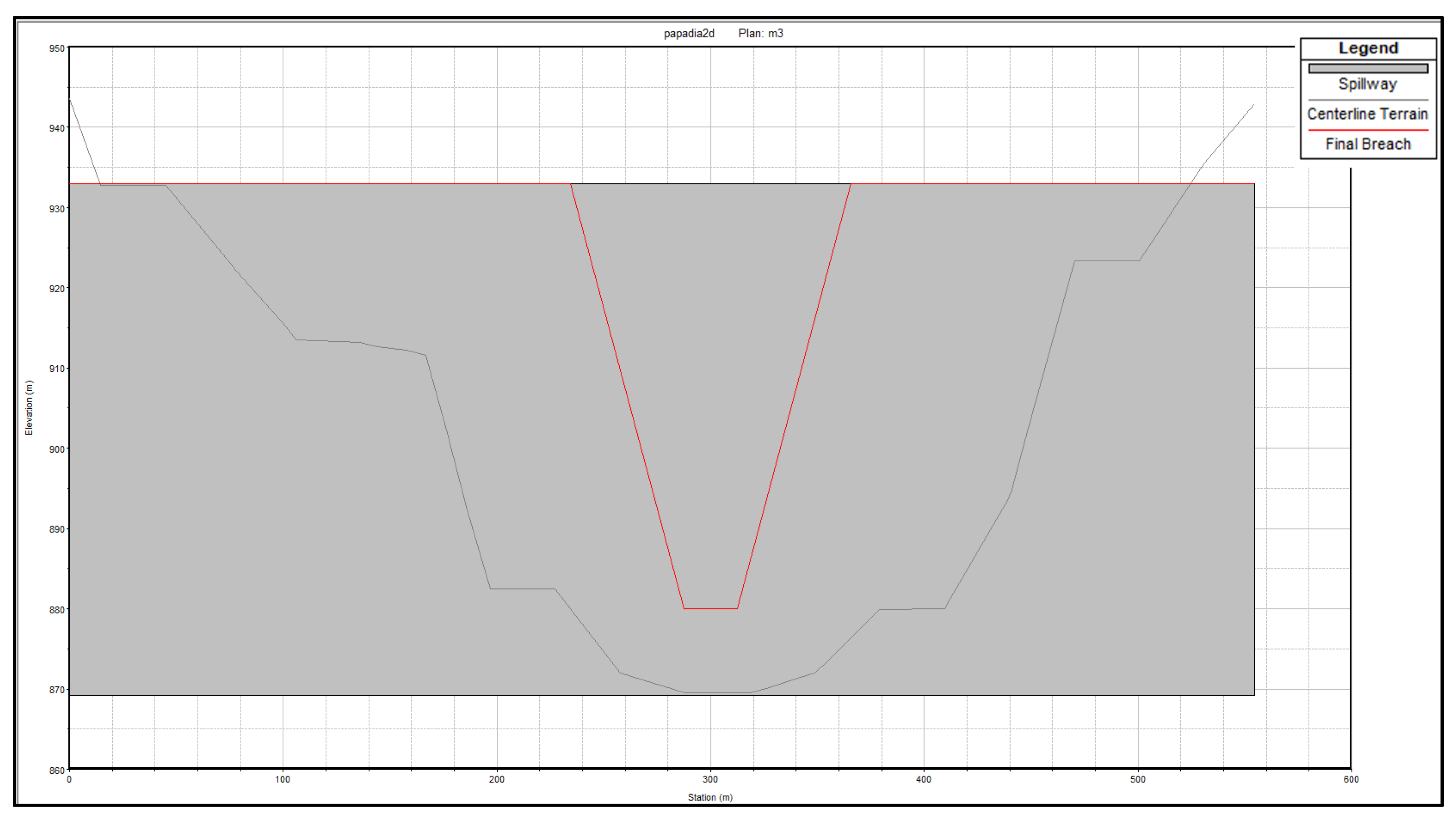
The breach location was assumed to be at the dam centreline. Figure 6 and Figure 7 present the final dam breach geometry for overtopping and piping, respectively, which seems to be quite similar, as the breach geometry is assumed to be trapezoidal for both cases. However, the resulting dimensions of the two failure modes are different due to different input parameter values.

3.3. Model Boundary Conditions

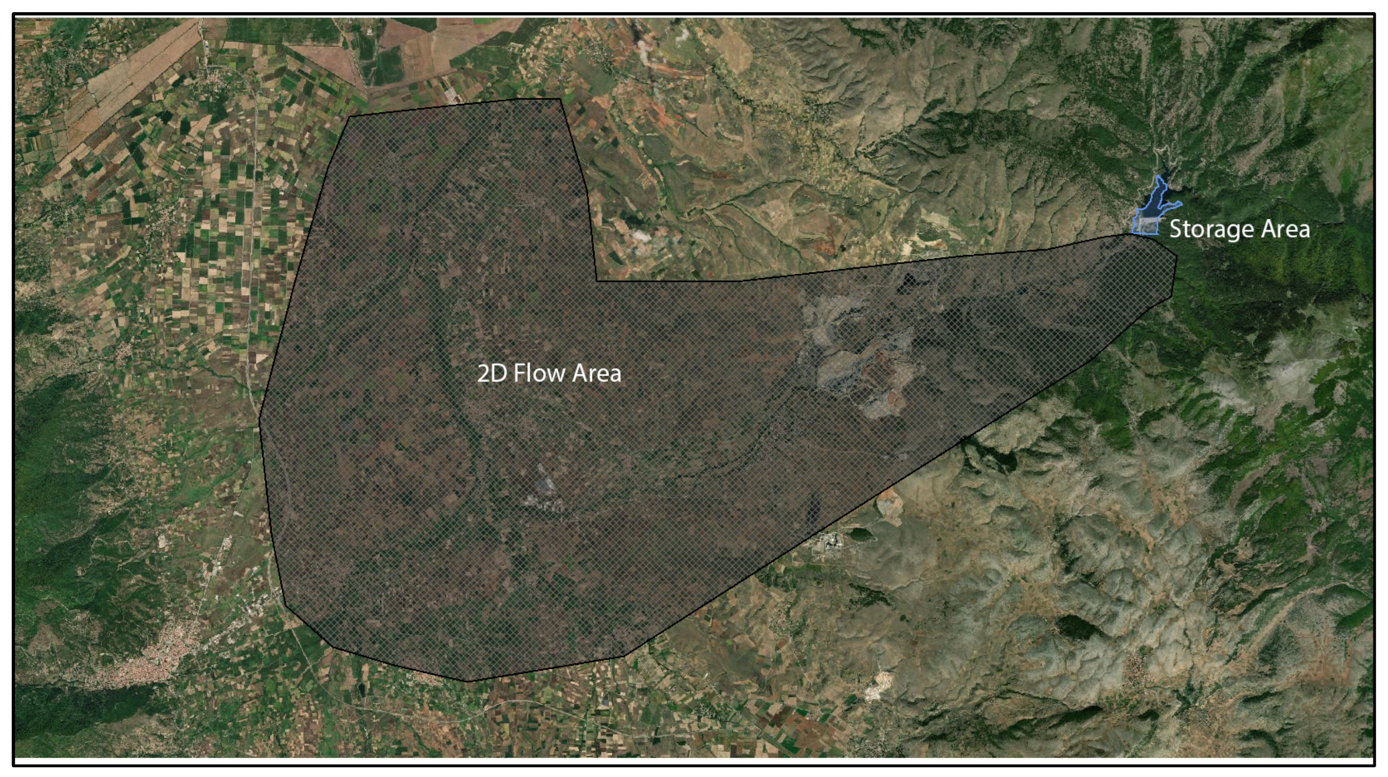
HEC-RAS simulates unsteady flow by building one-dimensional or two-dimensional models. In the first case, cross-sections are created along the floodwater path, and in the 2D model, the study area is represented by a grid composed of orthogonal cells. The main advantage of a 2D model is that it allows water to flow in a different direction, and the grid creates a more dense network for the representation of the ground surface. Therefore, water depth and velocity are simulated in a continuous way [48]. The grid cell size is selected according to the density of the geometric information, resolution of digital terrain, the extent of the study area so as to achieve model stability and a successful run. The Papadia dam study area is represented by a grid composed of 25 × 25 m cells including 27.699 cells. The grid that represents the study area is depicted in Figure 8.
Since there no hydrographs available on the downstream model area, the assumption of normal depth is often used in both cases, and in our study, it is applied for both piping and overtopping scenarios. For the upstream boundary conditions in the overtopping failure, the probable maximum flood hydrograph is applied. In the case of piping failure, the base flow hydrograph is applied.
As the true stage for a given flow at the downstream end of the model is not known, the normal depth is used as a boundary condition by means of the slope of the channel end and is calculated equal to 0.05 m/m.

3.4. Probable Maximum Flood (PMF)

The probable maximum flood (PMF) hydrograph was inserted as the upstream boundary condition in the reservoir. The PMF is the theoretically largest flood resulting from the combination of the most severe meteorological and hydrological conditions that could conceivably occur in a basin. It is used as a design criterion in hydraulic structures to avoid failures since the construction relies on extreme conditions. The calculation of PMF is based on integrating the probable maximum precipitation (PMP) and the characteristics of the upstream drainage basin.
There are two types of methods for converting PMP into PMF. The first type is the traditional unit hydrograph method. The second type is the river basin or hydrological process models. Such models require a number of factors and a large availability of data. Since in our case study, there are no observed runoff data in the area, which are essential for the calibration of hydrological models, the use of a synthetic unit hydrograph (SUH) method is preferred.
The PMP is the theoretically largest height of precipitation that may fall on a specific location in a given duration. The computation of PMP requires rainfall records, but it is also estimated by many meteorological models.
There are different methods used for PMP estimation, which can be categorized as hydrometeorological and statistical [49]. Standard hydrometeorological methods include moisture maximization method [50], storm transposition method [51], generalized method [50], storm separation method [52], and depth–area–duration method [53]. Conventional statistical methods include the Hershfield method [54] and its variants and multifractal method [55]. The Hershfield method, applied in this work, is more commonly used and can be applied if long-term precipitation data are available [49]. It is based on average precipitation and standard deviation of rainfall, similar to the Chow frequency factor method, and is expressed as follows for the estimation of PMP [56]:
PMP = X ¯ + k m s m
where X ¯ is the sample mean, and sm is the sample standard deviation of annual maximum precipitation values corresponding to a given duration, and km is the frequency factor.
The frequency factor is given as follows [57]:
k m = 20 8.6 ln X ¯ 130 + 1 24 d 0.4
where X ¯ is the sample mean of annual maximum precipitation values corresponding to a given duration d.
In this study, the PMP is estimated using precipitation data from the Florina meteorological station. It was the only station with long-term data and is representative of the study area. The maximum precipitation duration is 24 h, and the number of annual values is 44 (time series period: 1961–2004). Probable maximum precipitation (PMP) was found equal to 290.79 mm.
The alternating block method (ABM) is used to distribute the PMP by the Δt = 0.5 h time interval [56]. The ABM is a method to make the temporal rainfall distribution (design hyetograph) using the rainfall intensity–duration–frequency (I-D-F) curve. After dividing the rainfall duration T (h) by the Δt time interval, the rainfall intensities for the rainfall durations Δt, 2Δt, 3Δt, … are estimated from the rainfall I-D-F curve. By calculating the product of the rainfall intensity and the duration (i.e., the rainfall depth) for each rainfall duration, the cumulative rainfall distribution can be derived. The rainfall intensity data can then be obtained as the difference between the successive cumulative rainfall depths. After locating the rainfall peak at the centre of the distribution, the next largest rainfall intensity is located alternately to the right and left of the rainfall peak in turn.
In the context of the implementation of Directive 2007/60/EC, the Special Secretariat for Waters of Greece, as the competent body, assigned the preparation of studies related to the preparation of flood risk management plans in the 14 river basin districts of Greece. According to the relevant technical specifications, intensity–duration–frequency (I-D-F) curve equations (parametric relationships for calculating the intensity of rainfall (i) for a given duration (t) and return period (T)) were drawn up at the locations of the rain gauge stations in each river basin district. In this study, the I-D-F curve is derived from Florina station, as follows [58]:
i t , T = 265.5 T 0.126 0.69 1 + t 0.076 0.686
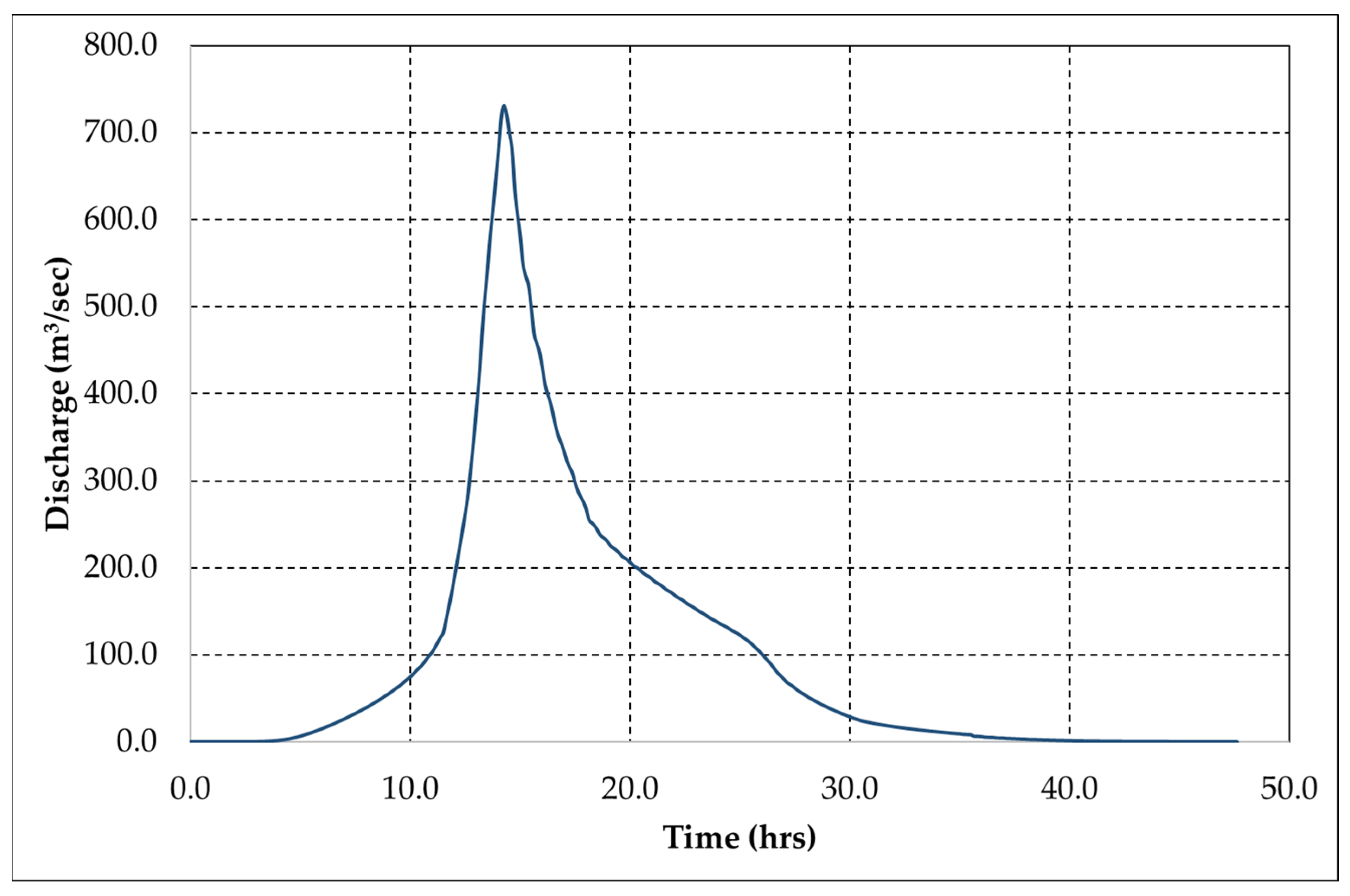
The PMF hydrograph estimation for the PMP is conducted by determining the effective rainfall of the runoff curve number of the Soil Conservation Service (SCS) and the Synthetic Unit Hydrograph of Sierra Nevada procedure, as described in “Design of Small Dams” [59]. The rainfall curve number for type II soil water condition, in our study area, was found equal to 85.4, and the parameter S was found equal to 43.4 mm. According to the Sierra Nevada synthetic unit hydrograph (SUH) method, the lag time of the unit hydrograph for the Papadia catchment was calculated equal to 3.32 h and the duration of unit rainfall equal to 0.6 h. In Figure 9, the PMF of the Papadia dam catchment that was used in the HEC-RAS model, for the overtopping scenario, is presented.

3.5. Flood Routing

The flood propagation simulation was performed using the fully dynamic shallow water (SW) equations which in the unidirectional form are also called Saint Venant equations.
The unsteady differential form of the mass conservation (continuity) equation is [37]:
H t + h u x + h v y + q = 0
where H is the water surface elevation, h is the water depth, t is time, u and v are the velocity components in the x- and y-directions, respectively, and q is a source/sink flux term.
The momentum equations are given as follows [37]:
u t + u u x + v u y = g H x + 1 h x v x x h u x + 1 h y v y y h u y c f u + τ s , x ρ h
v t + u v x + v v y = g H x + 1 h x v x x h v x + 1 h y v y y h v y c f v + τ s , x ρ h
where u and v are the velocities in the Cartesian directions, g is the gravitational acceleration, vxx and vyy are the horizontal eddy viscosity coefficients in the x and y directions, cf is the bottom friction coefficient, τs is the surface wind stress, and h is the water depth.
The water surface elevation H is given as follows [36]:
H = z + h
where z is the bottom surface elevation, and h is the water depth.
The unsteady flow equations solver in 2D HEC-RAS models uses an implicit finite volume algorithm, allowing for more computational time steps compared to the explicit methods. Using this algorithm, 2D flow areas are completely dry at the beginning of the simulation and can handle a sudden rush of water into the area [37]. The computational time step in the development of an unsteady flow simulation is critical for the stability of the model. The time step estimation is carried out according to the Courant–Friedrichs–Lewy condition:
C = V Δ t Δ x 1
where C is the Courant number, V is the flood wave velocity (wave celerity) (m/s −1), ∆t is the time step (s), and ∆x is the grid cell size (m).
In this study, the computational time step value was estimated by Eq. 10 following a trial-and-error procedure. The final value of the computational time step was found to be less than one due to a rapidly rising hydrograph and dry conditions in the channel before the start of the dam break [20].
In the unsteady flow simulation, the initial values of upstream flow and water elevation in the reservoir are required. In this work, upstream flow was considered negligible, and water surface was set at an elevation of 933 m a.s.l. (upper crest of the dam).

3.6. Flood Mapping

The RAS-Mapper was used in the 2D HEC-RAS model to visualize HEC-RAS results in a map-based format and to illustrate flow velocity values, water depth and flood arrival time at every point of the terrain created within the boundaries of the grid flow, which covers approximately 171 km2 downstream from the dam body. RAS-Mapper results were coupled with GIS data and Google Earth images to define the inundated areas and to evaluate possible threats that dam failure could pose on human lives and properties. The mapping output interval was set equal to one minute. The depth–velocity product is usually considered as a critical variable for damage from the collapse of buildings [60] and human instability [22]. The physical interpretation of the depth–velocity product is discussed in detail in the references [21,61,62].
The flood hazard assessment is performed using two classification approaches based on the product of water depth and velocity criterion, and the corresponding maps were created using RAS Mapper. The first classification approach adopts five flood severity classes (Table 5) concerning the potential hazard zones for building damage according to the Designing Safer Subdivisions—Guidance on Subdivision Design in Flood Prone Areas [63]. The second approach is more simplified and has been adopted as a hazard classification in the US and Canada (https://www.cityfloodmap.com/2013/12/flood-safety-guidelines-for-depth-and.html, accessed on 20 September 2022). It suggests that people would be at risk if the product of the velocity and the water depth exceeds 0.8 m2/s (9 ft2/s) as derived by the 3 × 3 empirical rule (3 ft of water depth times 3 ft/s of water velocity).

4. Results and Discussion

In both scenarios of overtopping and piping, the spillway was considered blocked, and the water surface in the reservoir was set at the dam crest height (933 m a.s.l.). At the beginning of the overtopping failure, it is considered that the maximum value of the probable maximum flood hydrograph (730.35 m3/s) occurs as inflow in the storage area. As concerns the piping scenario, a constant value equal to 0.02 m3/s was considered as inflow in the storage area. The critical simulation outputs of the study are presented in Table 6.
Τhe overtopping failure is the more dangerous case since the maximum discharge values at the dam and outlet are higher compared to the piping failure scenario (Table 6). To enhance the reliability of the results, a sensitivity analysis was performed for the model mesh size and for the breach parameters of the overtopping scenario. The selected mesh size 25 × 25 m, the smallest that can be used according to the available DEM analysis, is compared to two different geometries (50 × 50 and 100 × 100 m). The results presented in Table 7 show that larger mesh sizes can produce small decreases in the value and the arrival time of the maximum discharge on the outlet of the 2D flow area and quite a larger one on the maximum water depth, especially for 100 × 100 grid resolution.
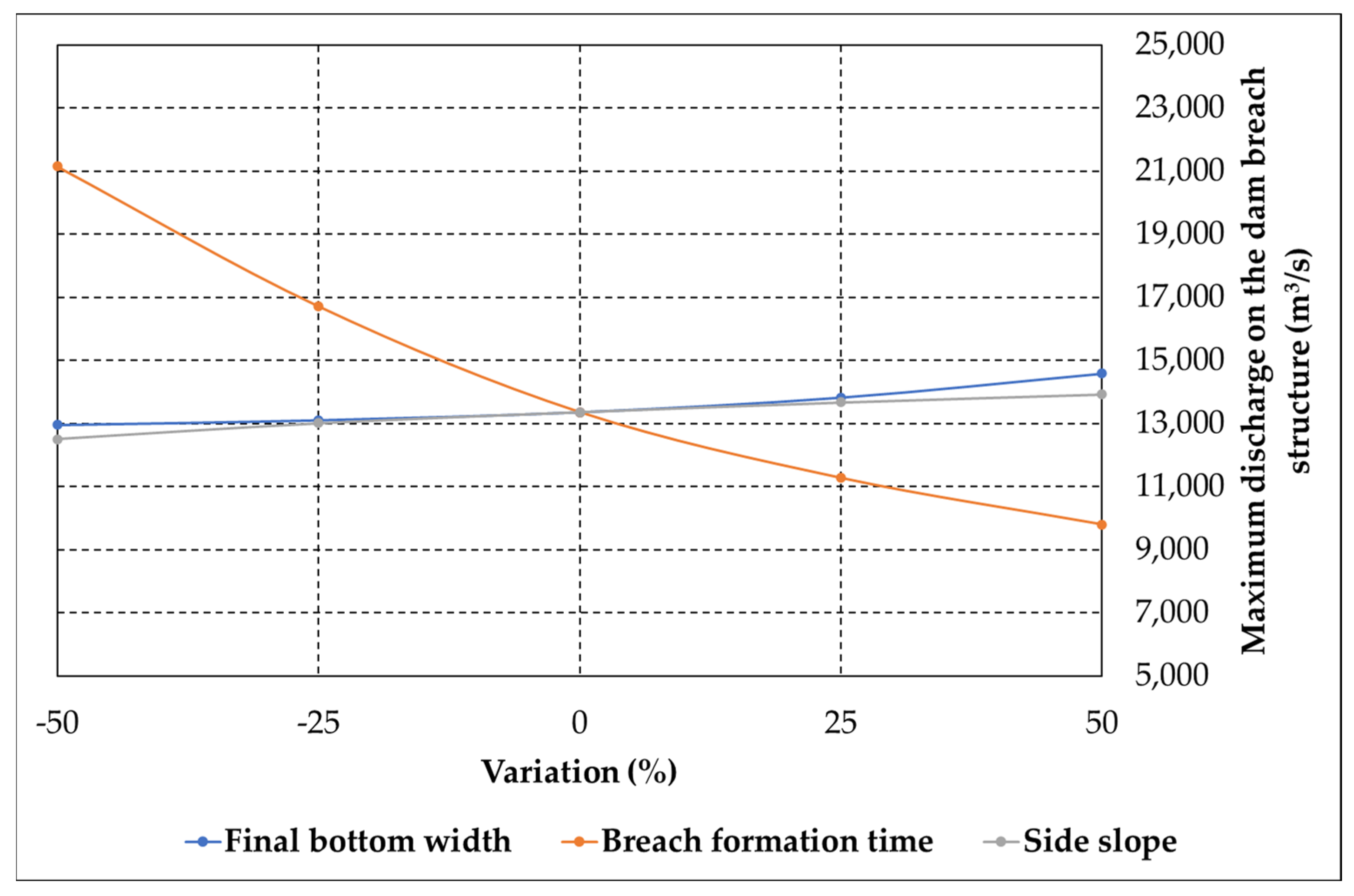
As concerns the breach parameters, the final breach bottom width, the side slope and the breach formation time obtained from the Froehlich equations [40] are used for the sensitivity analysis. A step change of ±25% is performed for each one of the above parameters, while the remaining ones are kept constant to examine their effect on maximum discharge, the occurrence time on the dam breach structure, and the maximum water depth. The results of the sensitivity analysis are presented in Figure 10, Figure 11 and Figure 12. Figure 10 indicates that maximum discharge on the dam breach structure increases with an increase in breach bottom width and side slope and decreases as the breach formation time is reduced. According to percentage change, maximum discharge on the dam breach structure is very sensitive to breach formation time.
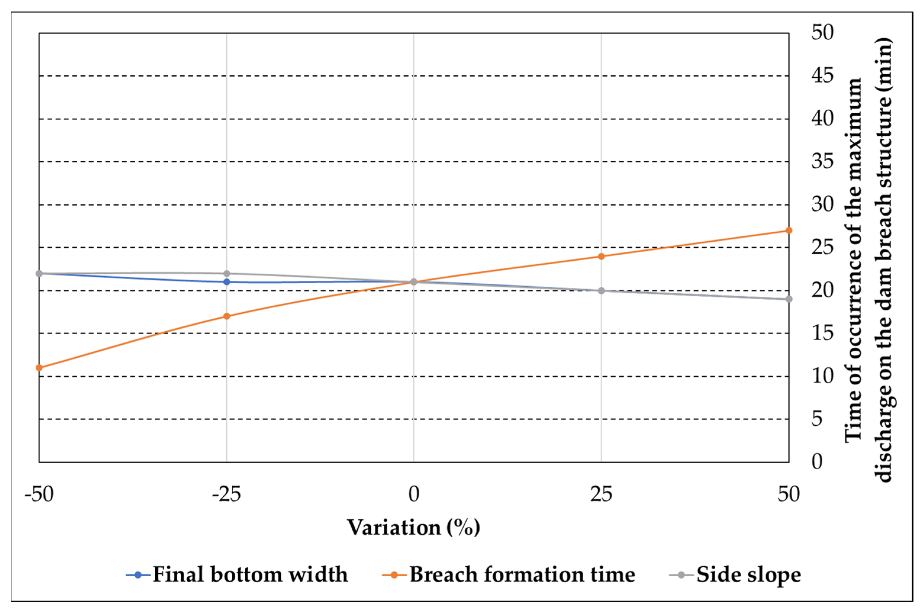
In Figure 11, the values of time of occurrence of the maximum discharge on the dam breach structure are presented according to the variation of breach parameters. A decrease in the peak flow occurrence time is observed with an increase in the final breach bottom width and side slope. The breach formation time appears to be the most critical parameter in this case, as an increase (or decrease) in its value produces a significant increase (or decrease), respectively, of the peak flow occurrence time on the dam structure.
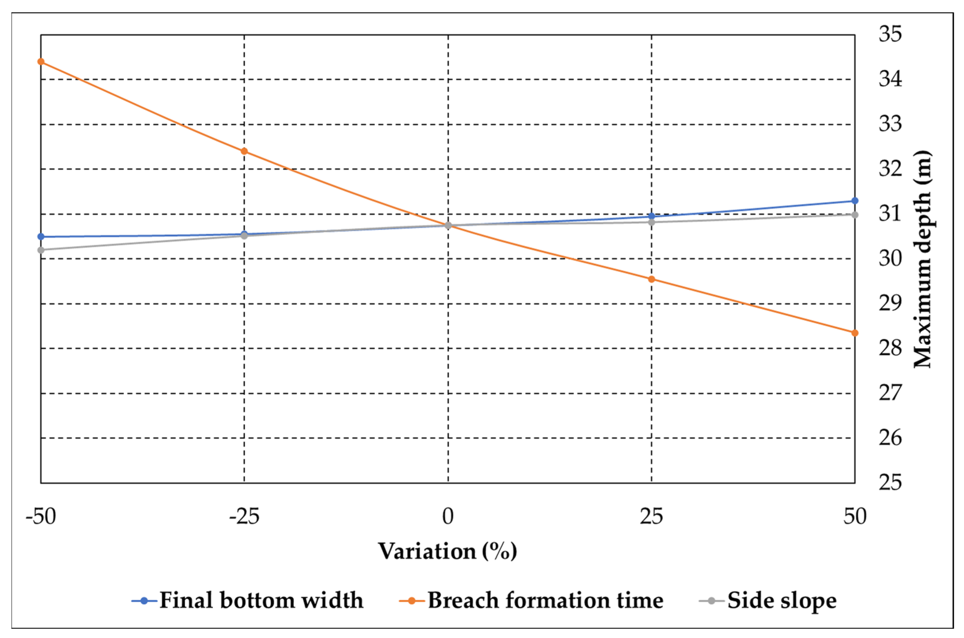
The maximum water depth, as shown in Figure 12, slightly increases with an increase in breach bottom width and side slope and has a declining trend related to breach formation time. In this case, the breach formation time is also found to be the parameter that has a greater impact on the maximum water depth.
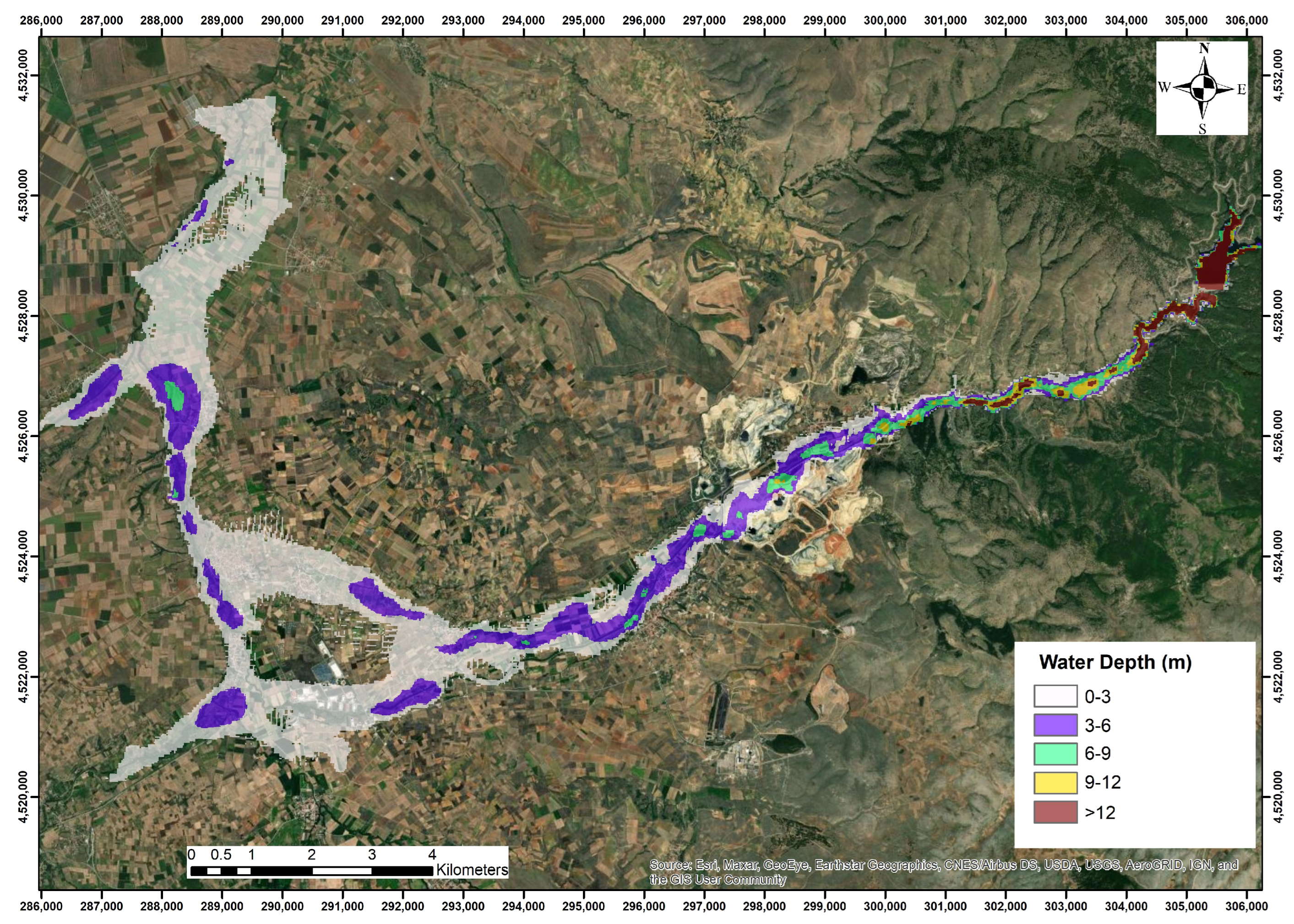
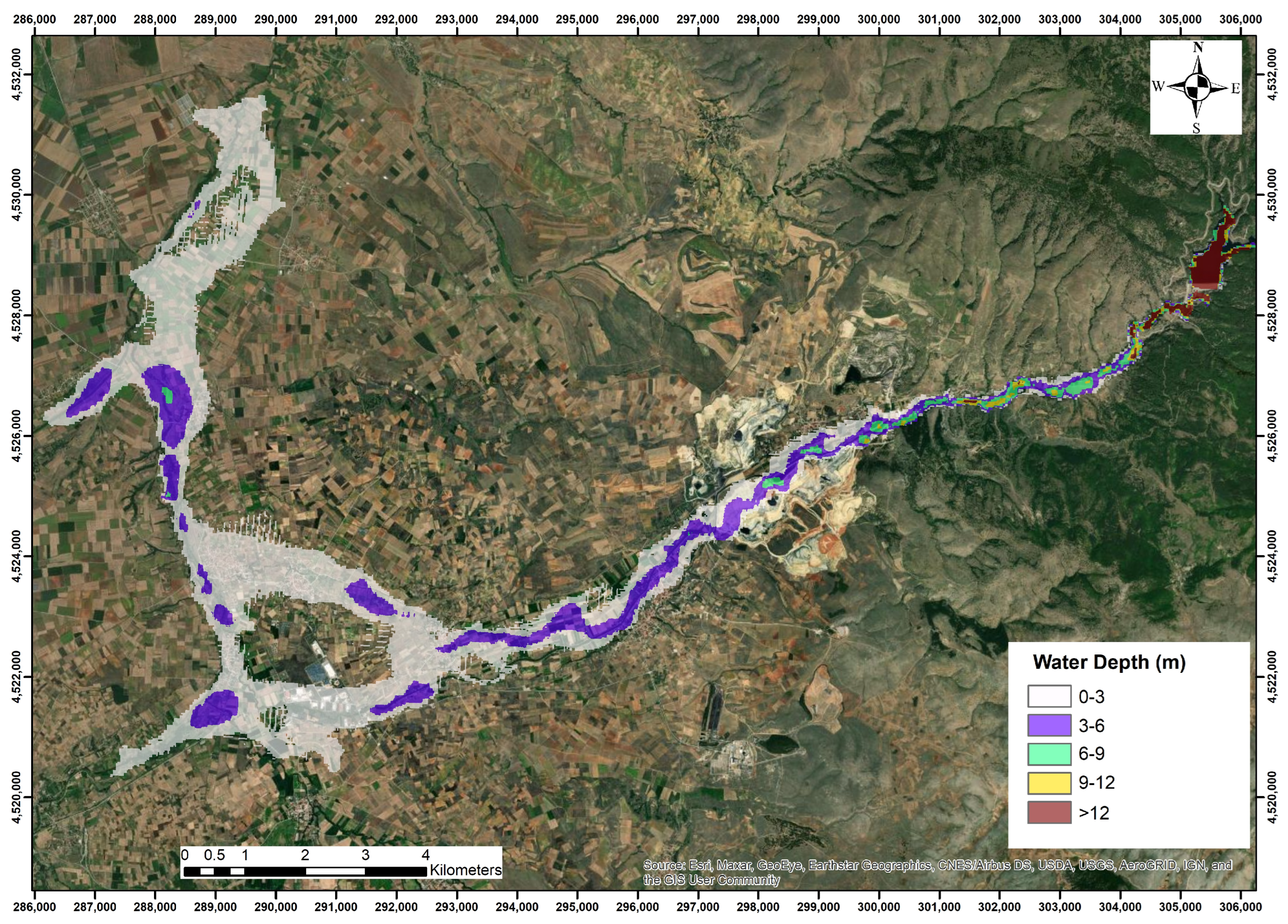
The results of the simulation model showed that the arrival times are shorter for the overtopping scenario, and the time difference between flood water occurrence and maximum discharge at the outlet is 63 and 49 min for the overtopping and piping scenarios, respectively (Table 6). The extent of the flooded area and the spatial distribution of flood water depth are depicted in Figure 13 and Figure 14 for the overtopping and piping scenarios, respectively, while in Table 8, the percentages of flooded area per severity class are given [16,64].
In the mountainous zone, overtopping failure results in a higher flood maximum water depth than piping (Figure 13 and Figure 14). In the plain area, which is located at a greater distance from the dam, the maximum water depth of both scenarios has small fluctuations, while the boundaries of the inundated area are quite similar (Figure 13 and Figure 14). The total inundated area for both scenarios is almost equal (25.01 and 23.16 km2) with the overtopping scenario having a slightly larger inundated area (Table 8). The maximum water depth for both scenarios is more than three meters for 21.76% and 20.51% of the total area. Furthermore, it exceeds six meters for 7.35% and 6.32% of the inundated area, which can be characterized as an extreme level of flood hazard [64,65]. The higher values of water depth occur mainly at locations near the dam (approximately at the first 7 km).
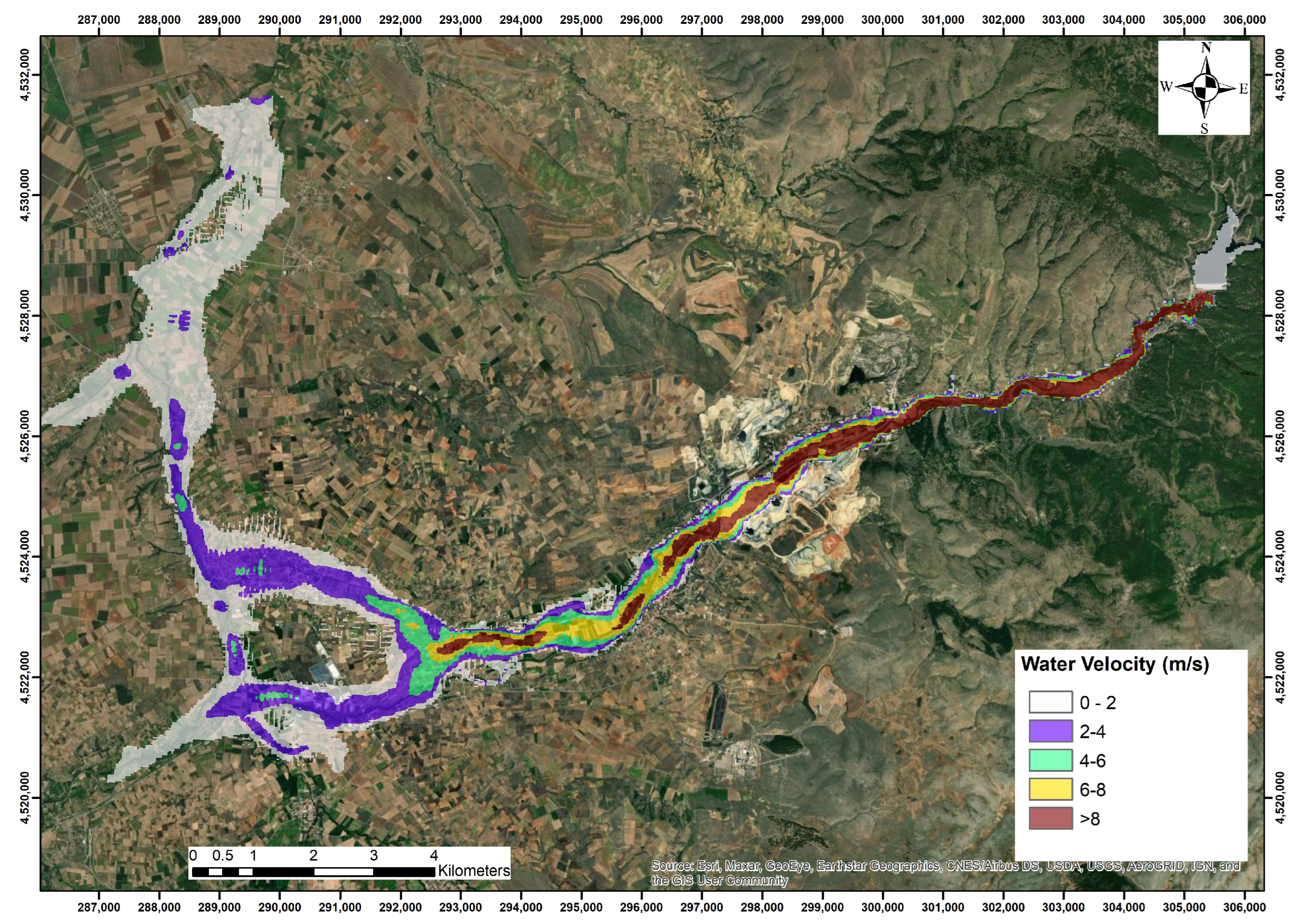
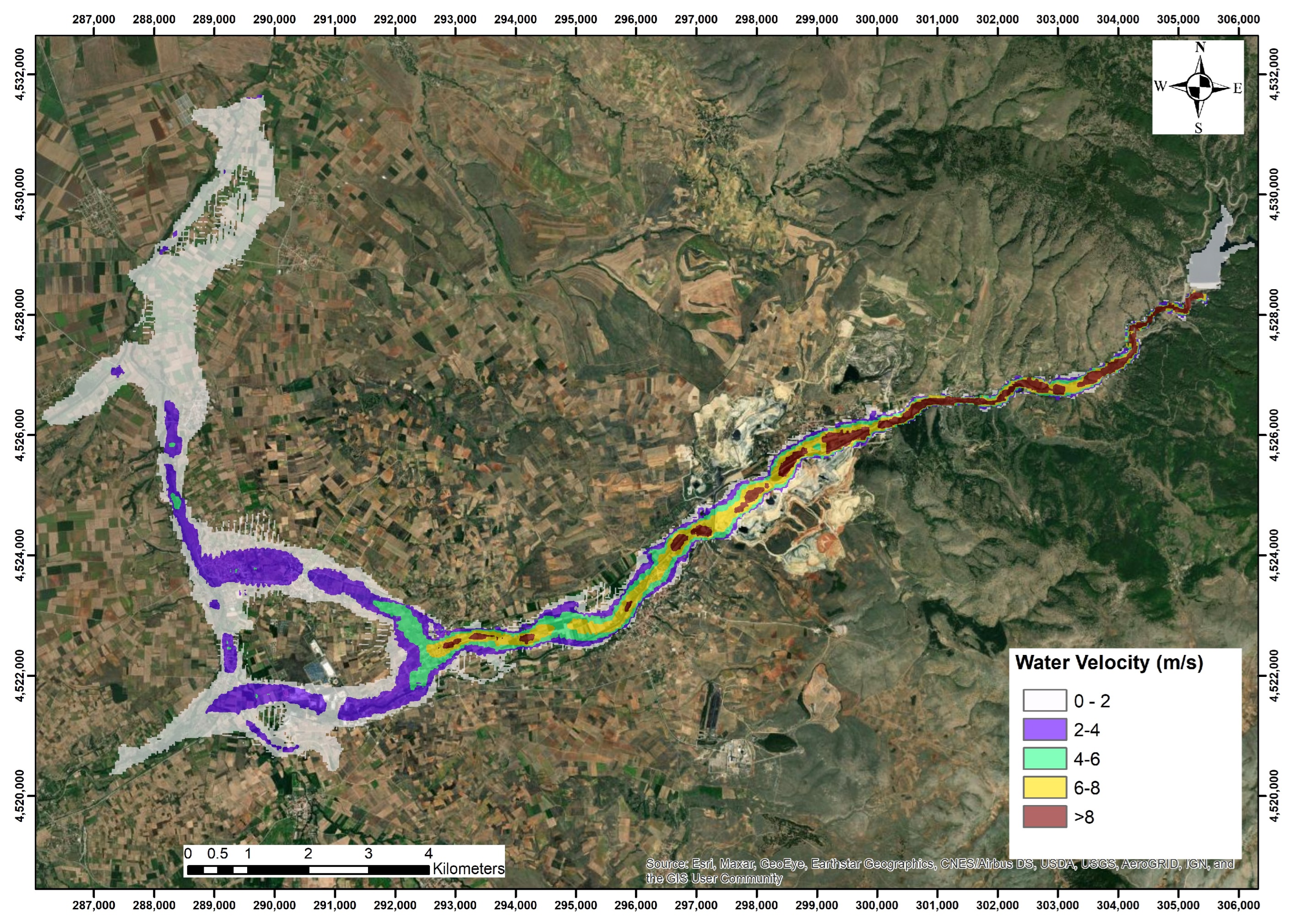
The maximum water velocity in the downstream area is presented for both cases in Figure 15 and Figure 16, while in Table 9, the percentages of flooded area per severity class are given [65].
As expected, the maximum water velocity value is much higher in the mountainous area compared to the plain area, and its higher value is depicted along the centre axis of the flood flow in the riverbed. The maximum velocities produced by overtopping and piping failures have similar values and spatial distribution (Figure 15 and Figure 16). According to Table 9, the maximum velocity is found to be more than 2 m/s for 45.32% and 43% of the inundated area for both scenarios, which can be characterized as an extreme danger [65]. The highest values of maximum velocity mainly occur in the first 15 km and specifically at locations of the mountainous area near the dam with steep slope.
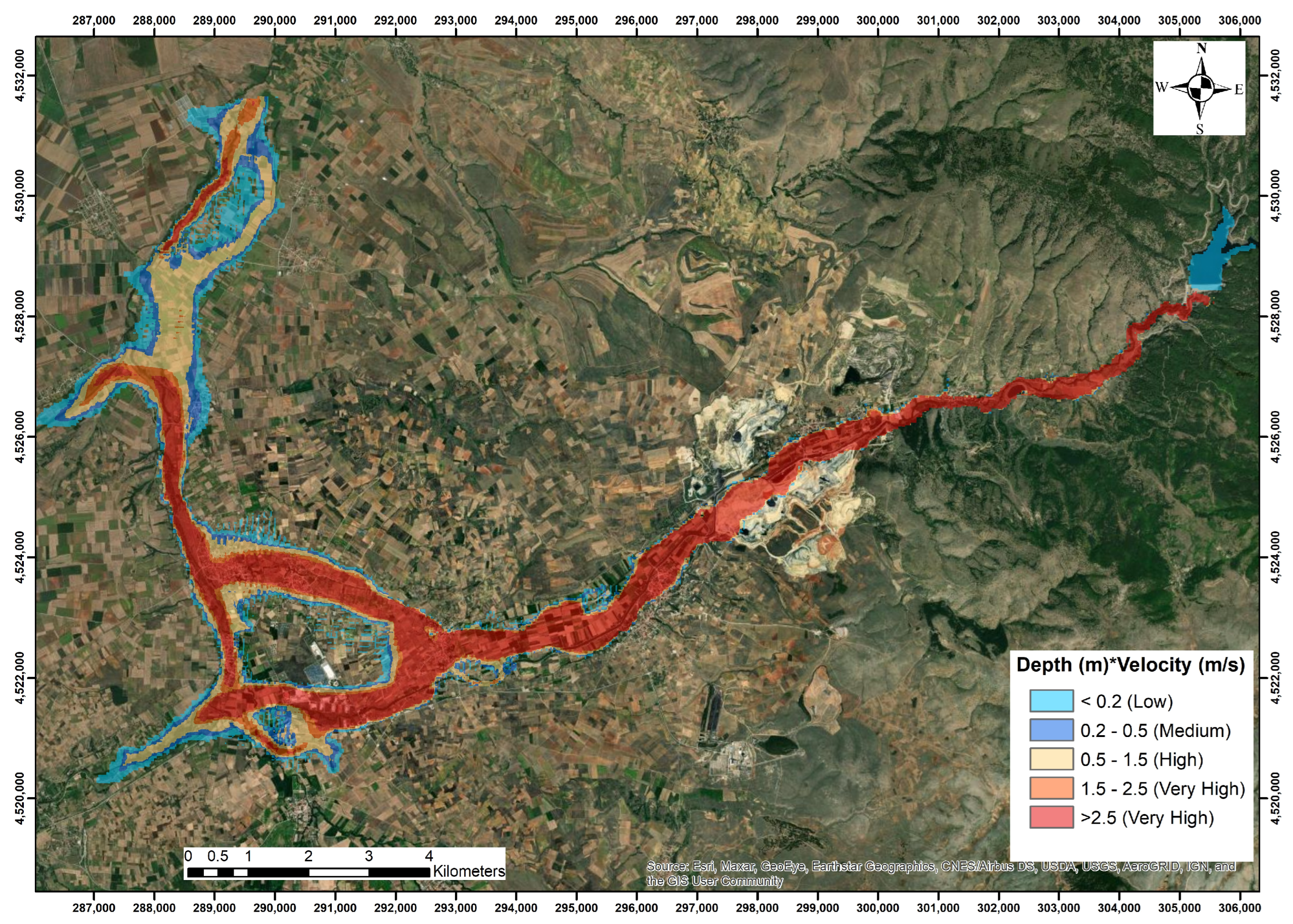
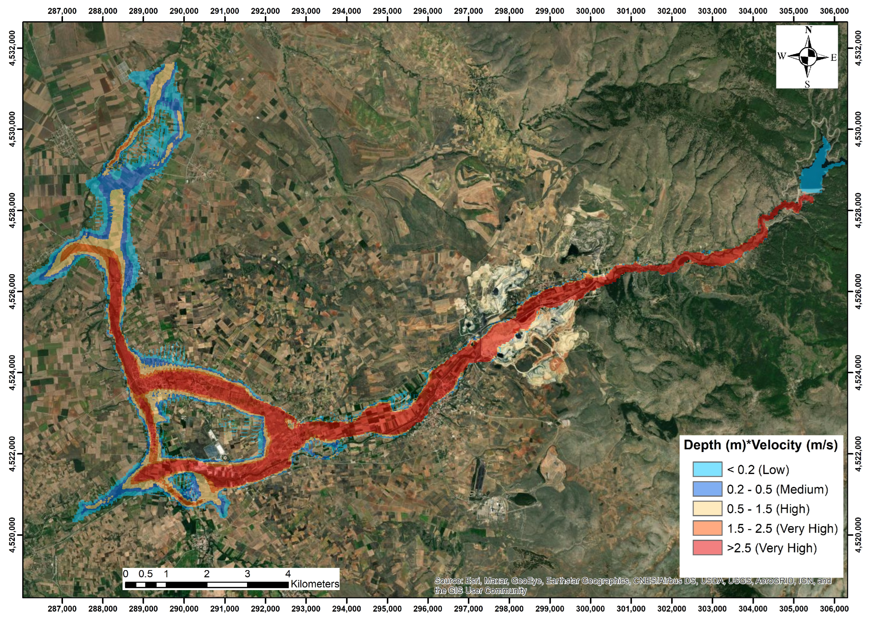
To have better insight into the flood hazard, the combination of water depth and velocity is also considered based on the two classification approaches as described above. The potential hazard zones for building damage according to the Designing Safer Subdivisions—Guidance on Subdivision Design in Flood Prone Areas (first classification approach) are presented in Figure 17 and Figure 18, and the percentages of area per severity class for the first classification approach are given in Table 10.
Within the boundaries of the inundated area, for both scenarios, the hazard is mainly characterized as high to extremely high for buildings, vehicles and infrastructure (Figure 17 and Figure 18). For the first classification method, 23 km downstream of the dam, following the water path, the flood severity is reduced to medium or even low mainly at the plain part of the study area. It was also revealed that the width of the dangerous zone in many locations exceeds by far the value of 1 km, and thus, flood water will possibly affect the nearby agricultural areas. The inundated area with extreme hazard is about 44.5% and 42% of the total inundated area for overtopping and piping failure scenarios, respectively (Table 10).
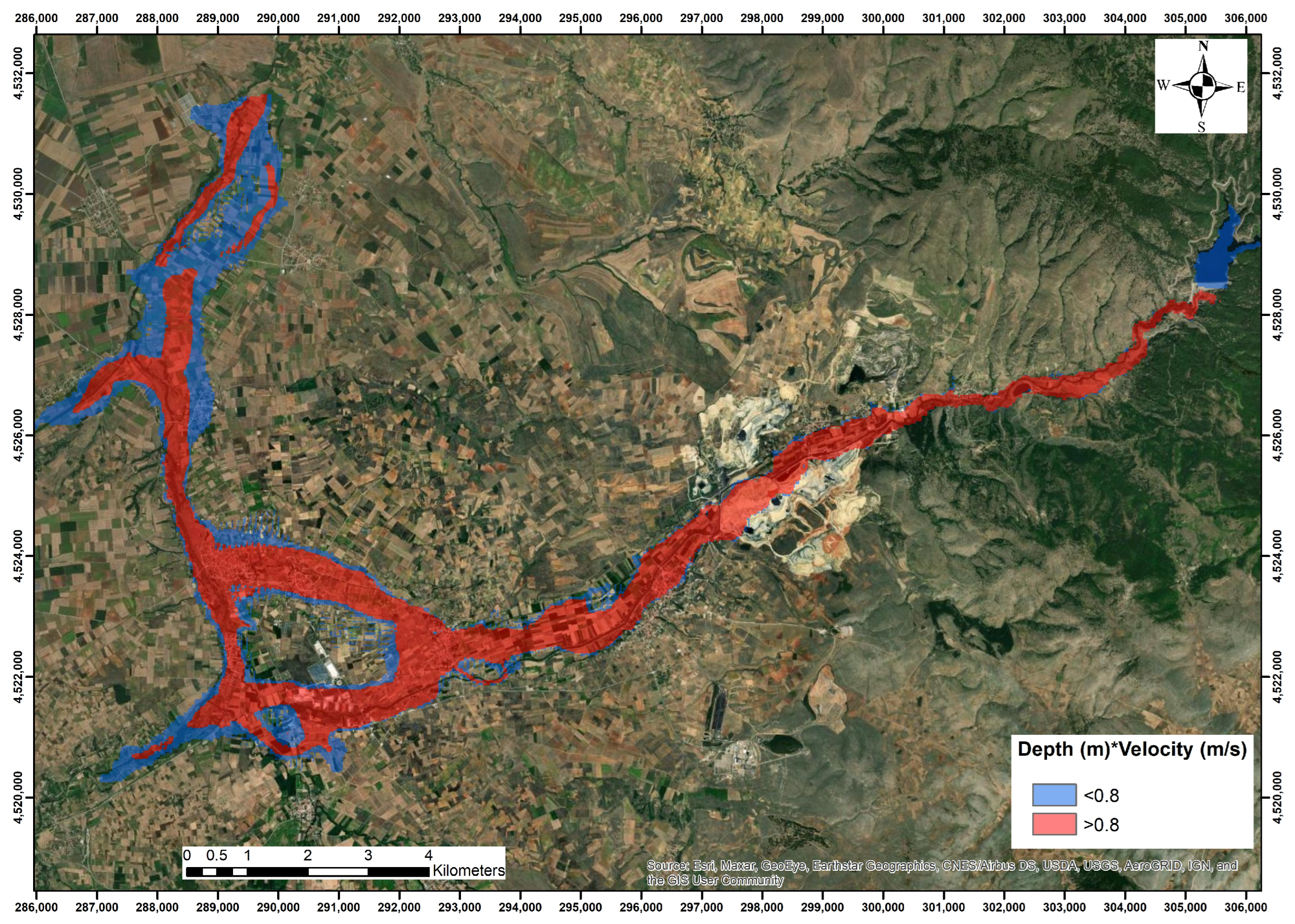
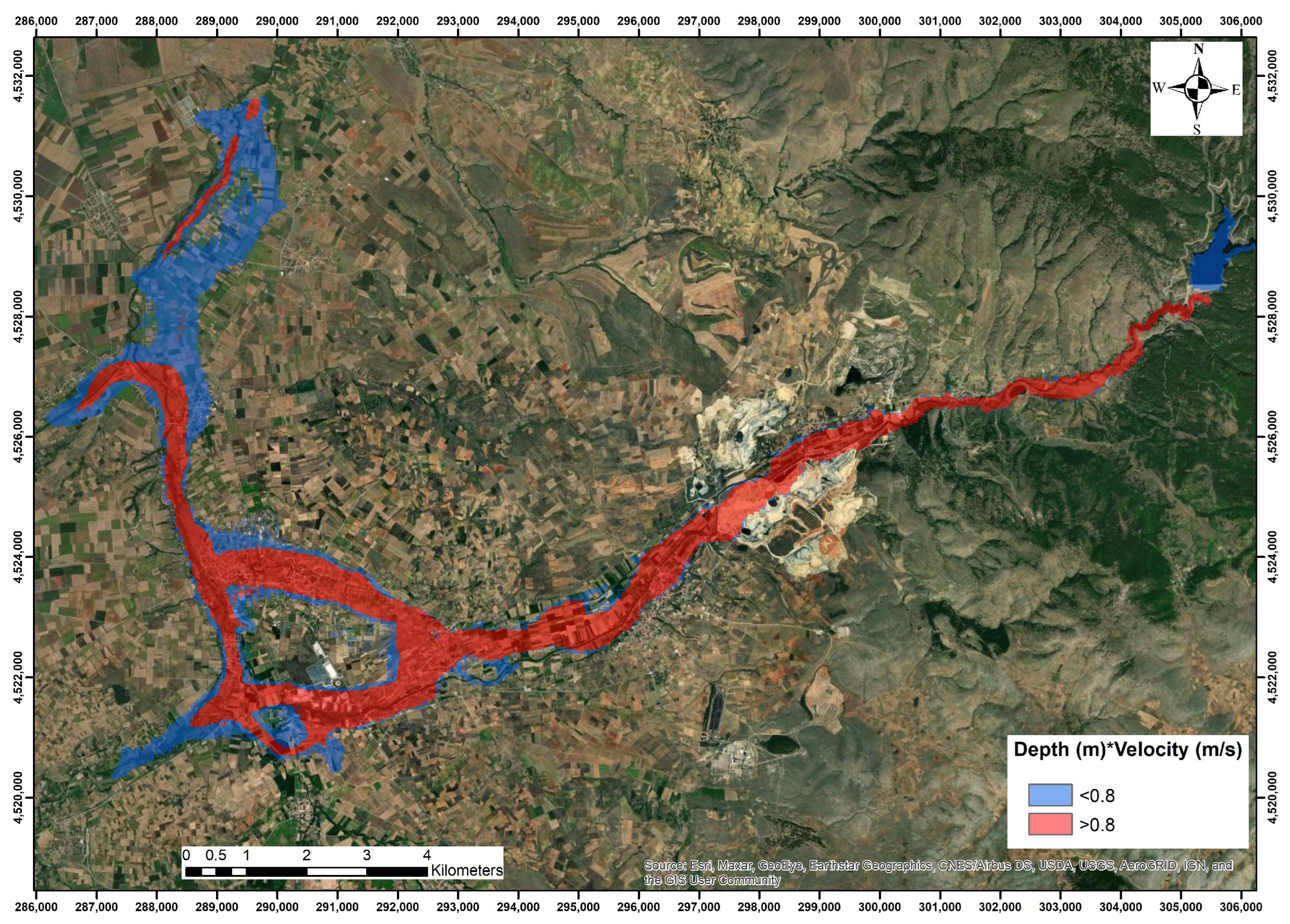
The potential human risk following the “3 × 3 rule” (second classification approach) is illustrated in Figure 19 and Figure 20, and the percentages of area per severity class are given in Table 11.
According to the threshold values set by the “3 × 3 rule” classification method, the high level of flood hazard is also confirmed, as 64.49% and 58.07% of the inundated area belong to this class for overtopping and piping scenarios, respectively (Table 11). For both scenarios, the class of high danger is dominant in the study area.
Since the inundated area for the two scenarios is quite similar, the distribution of the inundated area per land cover type only for the overtopping scenario (worst case) is presented (Table 12). Approximately 25 km2 will be inundated, and 93.84% of this area concerns agricultural activities.

5. Conclusions

A dam failure can have serious environmental, social and economic impacts. Hence, there is a need for flood risk assessment and the development of regional management plans. However, the exact mechanisms that can cause dam failure and the flooding phenomena procedures are usually less predictable, and the simulation procedure of such phenomena requires the knowledge of data and parameter values that are not always easily available. Despite these limitations, the simulation outcomes provide sufficient and reliable information for decisionmakers, managers, and authorities to create plans to manage a crisis and to avoid the disastrous impacts in case of a dam failure. In this study, a potential failure of the Papadia dam in northern Greece is investigated due to overtopping and piping conditions, and flood hazard maps are generated. To further enhance the reliability of model outputs and to investigate the impact of model parameters on them, a sensitivity analysis for the mesh size and breach parameters was performed. The breach formation time was found to be the most critical parameter, and the application of the densest mesh sizing corresponding to the available DEM data resolution was recommended. According to the dam failure modelling outputs, the maximum water depth and velocity values decreased from upstream to downstream in the inundated area. However, the very high values produced from these parameters may cause severe damage to most of the study area. The flood hazard was also assessed by means of the product of water depth and velocity using two classification approaches, and the resulting maps showed that the high-severity class is the dominant one in the study area. The analysis showed that both failure scenarios affect, to a similar extent, the downstream area, with the overtopping case producing higher values of depth, velocity and discharge, and consequently, it can be characterized as the most dangerous scenario. Agricultural and economical activities in the study area will be affected, as the cultivated land will be inundated. Evacuation time is crucial for the people and authorities to react, as the time interval between the first arrival of flood water and the maximum discharge through the outlet of the area is very short (about 1 h for overtopping scenario). The modelling outcomes could help authorities to start the planning and implementation of precautionary measures and monitoring systems. Furthermore, the produced maps can support the creation of management plans to handle a flood crisis, including warning systems and evacuation plans.

Author Contributions

Conceptualization, C.M., D.K., P.G. and T.T.; methodology, C.M., D.K. and P.G.; software, C.M., D.K. and P.G.; investigation, C.M., D.K. and P.G.; data curation, C.M., D.K. and P.G.; writing—original draft preparation, C.M., D.K. and P.G.; writing—review and editing, C.M., D.K., P.G. and T.T.; visualization, C.M., D.K. and P.G.; project administration, T.T.; funding acquisition, T.T. All authors have read and agreed to the published version of the manuscript.

Funding

This research is part of the project “Joint Cross Border Cooperation for Securing Societies against Natural and Man-Made Disasters (J-CROSS)” funded by Interreg IPA Cross border Cooperation Program “Greece—Republic of North Macedonia 2014–2020”.

Data Availability Statement

The data sets generated and analysed during the current study are available by the authors on reasonable request.

Conflicts of Interest

The authors declare no conflict of interest.

References

  1. Amini, A.; Bahrami, J.; Miraki, A. Effects of dam break on downstream dam and lands using GIS and Hec Ras: A decision basis for the safe operation of two successive dams. Int. J. River Basin Manag. 2021, 20, 487–498. [Google Scholar] [CrossRef]
  2. Greek Committee on Large Dams. Large dams of Greece. Athens 2013, Copyright by Greek Committee on Large Dams. Available online: https://eemf.gr/Fragmata_Elladas_201311.pdf (accessed on 5 December 2022).
  3. Maddamsetty, R.; Praveen, T.V.; Rao, S.S.; Manjulavani, K. Tehri Dam-breach versus monsoon flood routing in the Ganga River system. ISH J. Hydraul. Eng. 2010, 16, 109–131. [Google Scholar] [CrossRef]
  4. Tsakiris, G. Flood risk assessment: Concepts, modelling, applications. NHESS 2014, 14, 1361–1369. [Google Scholar] [CrossRef] [Green Version]
  5. Hall, J.; Arheimer, B.; Borga, M.; Brázdil, R.; Claps, P.; Kiss, A.; Kjeldsen, T.R.; Kriaučiūnienė, J.; Kundzewicz, Z.W.; Lang, M.; et al. Understanding flood regime changes in Europe: A state-of-the-art assessment. HESS 2014, 18, 2735–2772. [Google Scholar] [CrossRef] [Green Version]
  6. Kreibich, H.; Di Baldassarre, G.; Vorogushyn, S.; Aerts, J.C.; Apel, H.; Aronica, G.T.; Arnbjerg-nielsen, K.; Bouwer, L.M.; Bubeck, P.; Caloiero, T.; et al. Earth’s Future Special Section: Adaptation to flood risk: Results of international paired flood event studies. Earth’s Future 2017, 5, 953–965. [Google Scholar] [CrossRef] [Green Version]
  7. Chen, S.C.; Lin, T.W.; Chen, C.Y. Modeling of natural dam failure modes and downstream riverbed morphological changes with different dam materials in a flume test. Eng. Geol. 2015, 188, 148–158. [Google Scholar] [CrossRef]
  8. Derdous, O.; Djemili, L.; Bouchened, H.; Tachi, S.E. A GIS based approach for the prediction of the dam break flood hazard—A case study of Zardezas reservoir “Skikda, Algeria”. J. Water Land Dev. 2015, 27, 15–20. [Google Scholar] [CrossRef] [Green Version]
  9. Bonnet, M.; Witt, A.; Stewart, K.; Hadjerioua, B.; Mobley, M. The Economic Benefits of Multipurpose Reservoirs in the United States-Federal Hydropower Fleet; National Technical Information Service: Springfield, VA, USA, 2015. [Google Scholar]
  10. Kumar, S.; Jaswal, A.; Pandey, A.; Sharma, N. Literature review of dam break studies and inundation mapping using hydraulic models and GIS. Int. Res. J. Eng. Technol. 2017, 4, 55–61. [Google Scholar]
  11. Zhang, L.; Peng, M.; Chang, D.; Xu, Y. Dam breach modeling. In Dam Failure Mechanisms and Risk Assessment; John Wiley & Sons: Singapore, 2016; pp. 161–221. [Google Scholar] [CrossRef]
  12. Cao, Z.; Huang, W.; Pender, G.; Liu, X. Even more destructive: Cascade dam break floods. J. Flood Risk Manag. 2014, 7, 357–373. [Google Scholar] [CrossRef]
  13. Bellos, V.; Tsakiris, V.K.; Kopsiaftis, G.; Tsakiris, G. Propagating dam breach parametric uncertainty in a river reach using the HEC-RAS software. Hydrology 2020, 7, 72. [Google Scholar] [CrossRef]
  14. Centre for Research on the Epidemiology of Disasters (CRED). Summarized Table of Natural Disasters in Greece from 1900 to 2017, EM-DAT: The CRED/OFDA International Disaster Database–www.emdat.be–Université Catholique de Louvain–Brussels–Belgium. Available online: http://www.emdat.be (accessed on 12 January 2018).
  15. You, L.; Li, C.; Min, X.; Xiaolei, T. Review of dam-break research of earth-rock dam combining with dam safety management. Procedia Eng. 2012, 28, 382–388. [Google Scholar] [CrossRef] [Green Version]
  16. Karim, I.R.; Hassan, Z.F.; Abdullah, H.H.; Alwan, I.A. 2D-HEC-RAS modeling of flood wave propagation in a Semi-Arid Area due to dam overtopping failure. Civ. Eng. J. 2021, 7, 1501–1514. [Google Scholar] [CrossRef]
  17. Zhang, L.M.; Xu, Y.; Jia, J.S. Analysis of earth dam failures: A database approach. Georisk 2009, 3, 184–189. [Google Scholar] [CrossRef] [Green Version]
  18. Froehlich, D.C. Peak outflow from breached embankment dam. J. Water Resour. Plan. Manag. 1995, 121, 90–97. [Google Scholar] [CrossRef]
  19. Yi, X. A Dam Break Analysis Using HEC-RAS. JWARP 2011, 3, 370–379. [Google Scholar]
  20. Clausen, L.K. Potential Dam Failure: Estimation of Consequences, and Implications for Planning. Master’s Thesis, School of Geography and Planning, Middlesex Polytechnic Collaborating with Binnie and Partners, Redhill, UK, 1989. [Google Scholar]
  21. Pistrika, A.K.; Jonkman, S.N. Damage to residential buildings due to flooding of New Orleans after hurricane Katrina. Nat. Hazards 2010, 54, 413–434. [Google Scholar] [CrossRef]
  22. Jonkman, S.N.; Penning-Rowsell, E. Human instability in flood flows. JAWRA 2008, 44, 1208–1218. [Google Scholar]
  23. Australian Emergency Management Institute (AEMI). Technical Flood Risk Management Guideline: Flood Hazard; AEMI: Canberra, Australia, 2014. [Google Scholar]
  24. El-Naqa, A.; Jaber, M. Floodplain analysis using ArcGIS, HEC-GeoRAS and HEC-RAS in Attarat Um Al-Ghudran oil shale concession area, Jordan. J. Civil Enviro. Eng. 2018, 8, 1–11. [Google Scholar] [CrossRef]
  25. Shahrim, M.F.; Ros, F.C. Estimation of breach outflow hydrograph using selected regression breach equations. IOP Conf. Ser. Earth Environ. Sci. 2020, 476, 012129. [Google Scholar] [CrossRef]
  26. Balaji, B.; Kumar, S. Dam breach analysis of Kalyani Dam using HEC-RAS. Int. J. Civ. Eng. IJCIET 2018, 9, 372–380. [Google Scholar]
  27. Psomiadis, E.; Tomanis, L.; Kavvadias, A.; Soulis, K.X.; Charizopoulos, N.; Michas, S. Potential dam breach analysis and flood wave risk assessment using HEC-RAS and remote sensing data: A multicriteria approach. Water 2021, 13, 364. [Google Scholar] [CrossRef]
  28. Urzică, A.; Mihu-Pintilie, A.; Stoleriu, C.C.; Cîmpianu, C.I.; Huţanu, E.; Pricop, C.I.; Grozavu, A. Using 2D HEC-RAS modeling and embankment dam break scenario for assessing the flood control capacity of a multi-reservoir system (NE Romania). Water 2021, 13, 57. [Google Scholar] [CrossRef]
  29. Bharath, A.; Shivapur, A.V.; Hiremath, C.G. Dam break flood routing and inundation mapping using HEC-RAS and HEC-GeoRAS. In Water Resources Management and Reservoir Operation; Springer: Cham, Switzerland, 2021; pp. 129–137. [Google Scholar]
  30. Iroume, J.Y.A.; Onguéné, R.; Djanna Koffi, F.; Colmet-Daage, A.; Stieglitz, T.; Essoh Sone, W.; Etame, J. The 21st August 2020 Flood in Douala (Cameroon): A Major Urban Flood Investigated with 2D HEC-RAS Modeling. Water 2022, 14, 1768. [Google Scholar] [CrossRef]
  31. Brunner, G. Using HEC-RAS for Dam Break Studies; TD-39, Us Army Corps Eng. Hydrologic Engineering Center: Davis, CA, USA, 2016. [Google Scholar]
  32. Bharath, A.; Shivapur, A.V.; Hiremath, C.G.; Maddamsetty, R. Dam break analysis using HEC-RAS and HEC-GeoRAS: A case study of Hidkal dam, Karnataka state, India. Environ. Chall. 2021, 5, 100401. [Google Scholar] [CrossRef]
  33. Kazakis, N.T.; Voudouris, K.S. Hydrometeorological and Hydrogeological Data of Florina Basin, Florina Prefecture, Western Macedonia Region, Greece. Technical Report, Interreg III B, WATER-MAP. 2008. Available online: http://www.kepekozani.gr/program/arc/a.pdf#page=22 (accessed on 5 December 2022).
  34. Koukouzas, N.; Tasianas, A.; Gemeni, V.; Alexopoulos, D.; Vasilatos, C. Geological modelling for investigating CO2 emissions in Florina Basin, Greece. Open Geosci. 2015, 7. [Google Scholar] [CrossRef]
  35. Srinivas, K.; Werner, M.; Wright, N. Comparing forecast skill of inundation models of differing complexity: The case of Upton upon Severn. In Flood Risk Management: Research and Practice; CRC Press: Boca Raton, FL, USA, 2008; p. 25. [Google Scholar]
  36. Yakti, B.P.; Adityawan, M.B.; Farid, M.; Suryadi, Y.; Nugroho, J.; Hadihardaja, I.K. 2D modeling of flood propagation due to the failure of way Ela natural dam. In MATEC Web of Conferences (SIBE 2017); EDP Sciences: Les Ulis, France, 2018; Volume 147, p. 03009. [Google Scholar] [CrossRef] [Green Version]
  37. Brunner, G. HEC-RAS River Analysis System, 2D Modelling User’s Manual, Version 5.0.7; Us Army Corps Eng. Hydrologic Engineering Center: Davis, CA, USA, 2016. [Google Scholar]
  38. Papaioannou, G.; Loukas, A.; Vasiliades, L.; Aronica, G.T. Flood inundation mapping sensitivity to riverine spatial resolution and modeling approach. Nat. Hazards 2016, 83, 117–132. [Google Scholar] [CrossRef]
  39. Teng, J.; Jakeman, A.J.; Vaze, J.; Croke, B.F.; Dutta, D.; Kim, S.J.E.M. Flood inundation modeling: A review of methods, recent advances and uncertainty analysis. Environ. Model. Softw. 2017, 90, 201–216. [Google Scholar] [CrossRef]
  40. Froehlich, D.C. Embankment dam breach parameters and their uncertainties. J. Hydraul. Eng. 2008, 134, 1708–1721. [Google Scholar] [CrossRef]
  41. MacDonald, T.C.; Langridge-Monopolis, J. Breaching characteristics of dam failures. J. Hydraul. Eng. 1984, 110, 567–586. [Google Scholar] [CrossRef]
  42. Von Thun, J.L.; Gillette, D.R. Guidance on Breach Parameters; US Department of the Interior, Bureau of Reclamation: Denver, CO, USA, 1990. [Google Scholar]
  43. Xu, Y.; Zhang, L.M. Breaching parameters for earth and rockfill dams. J. Geoteh. Geoenviron. 2009, 135, 1957–1970. [Google Scholar] [CrossRef]
  44. Chow, V.T. Open Channel Hydraulics; Blackburn Press: Caldwell, NJ, USA, 1959. [Google Scholar]
  45. NRCS. Manning’s n Values for Various Land Covers to Use for Dam Breach Analyses by NRCS in Kansas; NRCS: Washington, DC, USA, 2016. [Google Scholar]
  46. Papaioannou, G.; Efstratiadis, A.; Vasiliades, L.; Loukas, A.; Papalexiou, S.M.; Koukouvinos, A.; Kossieris, P. An operational method for flood directive implementation in ungauged urban areas. Hydrology 2018, 5, 24. [Google Scholar] [CrossRef] [Green Version]
  47. Akoh, R.; Ishikawa, T.; Kojima, T.; Tomaru, M.; Maeno, S. High-resolution modeling of tsunami run-up flooding: A case study of flooding in Kamaishi city, Japan, induced by the 2011 Tohoku tsunami. NHESS 2017, 17, 1871–1883. [Google Scholar] [CrossRef] [Green Version]
  48. Ghimire, E.; Sharma, S.; Lamichane, N. Evaluation of one-dimensional and two-dimensional HEC-RAS models to predict flood travel time and inundation area for flood warning system. ISH J. Hydraul. Eng. 2022, 28, 110–126. [Google Scholar] [CrossRef]
  49. World Meteorological Organization. Manual on Estimation of Probable Maximum Precipitation (PMP); World Meteorological Organization: Geneva, Switzerland, 2009; No 1045. [Google Scholar]
  50. Wang, G. Probable Maximum Precipitation: Approaches and Methodology. Twelfth Session of the Commission for Hydrology of the World Meteorological Organization, 20–29 October 2004. Available online: https://www.yrce.cn/yrexport/whole.asp?id=wgan (accessed on 5 December 2022).
  51. Xuereb, K.; Moore, G.; Taylor, B. Development of the Method of Storm Transposition and Maximization for the West Coast of Tasmania (HRS Report No. 7); Hydrology Report Series; Hydrometeorological Advisory Services, Australian Bureau of Meteorology: Melbourne, Australia, 2001. [Google Scholar]
  52. Hansen, E.M. Probable Maximum Precipitation Estimations—United States between the Continental Divide and the 103rd Meridian (HMR No. 55A); United States Department of Commerce, National Oceanic and Atmospheric Administration, United States Department of Army Corps of Engineers, United States Department of Interior Bureau of Reclamation: Silver Spring, MD, USA, 1988. [Google Scholar]
  53. Zhang, Y.; Wang, Z. Estimating probable maximum storms in the middle and upper reaches of the Changjiang River using generalized depth-area-duration method. J. China Hydrol. 1988, 18, 13–18. [Google Scholar]
  54. Hershfield, D.M. Method for Estimating Probable Maximum Precipitation. J. AWWA 1965, 57, 965–972. [Google Scholar] [CrossRef]
  55. Douglas, E.M.; Barros, A.P. Probable maximum precipitation estimation using multifractals: Application in the eastern United States. J. Hydrometeorol. 2003, 4, 1012–1024. [Google Scholar] [CrossRef]
  56. Chow, V.T.; Maidment, D.R.; Mays, L.W. Applied Hydrology; MacGraw-Hill Inc.: New York, NY, USA, 1988. [Google Scholar]
  57. Koutsoyiannis, D.; Xanthopoulos, T. Engineering Hydrology, 3rd ed.; National Technical University of Athens: Athens, Greek, 1999; 418p. [Google Scholar] [CrossRef]
  58. Special Secretariat for Waters of Greece. Implementation of Directive 2007/60/EC-Preparation of Intensity–Duration–Frequency (I-D-F) Curves at Country Level (in Greek). 2016. Available online: https://floods.ypeka.gr/egyFloods/IDF/IDF_Report_V4.pdf) (accessed on 5 December 2022).
  59. Duncan, W.; Huntley, C.; Hokenstrom, J.; Cudworth, A.; McDaniel, T. Design of Small Dams. A Water Resources Technical Publication; Final Report (No. PB-95-176368/XAB); Bureau of Reclamation, Engineering and Research Center: Denver, CO, USA, 1987. [Google Scholar]
  60. Brunner, G.W. 2D Modeling and Mapping with HEC-RAS v. 5 Monticello Dam Breach. US Army Corps of Engineers: Davis, CA, USA, 2015. [Google Scholar]
  61. Musolino, G.; Ahmadian, R.; Falconer, R.A. Comparison of flood hazard assessment criteria for pedestrians with a refined mechanics-based method. J. Hydrol. X 2020, 9, 100067. [Google Scholar] [CrossRef]
  62. Zhu, Z.; Zhang, Y.; Gou, L.; Pang, B. An Entropic Approach to Estimating the Instability Criterion of People in Floodwaters. Entropy 2021, 23, 74. [Google Scholar] [CrossRef] [PubMed]
  63. Hawkesbury-Nepean Floodplain Management Steering Committee. Designing Safer Subdivisions on Floodplains; Hawkesbury-Nepean Floodplain Management Steering Committee: Parramatta, Australia, 2006. [Google Scholar]
  64. Mihu-Pintilie, A.; Cîmpianu, C.I.; Stoleriu, C.C.; Pérez, M.N.; Paveluc, L.E. Using high-density LiDAR data and 2D streamflow hydraulic modeling to improve urban flood hazard maps: A HEC-RAS multi-scenario approach. Water 2019, 11, 1832. [Google Scholar] [CrossRef] [Green Version]
  65. Oeh, O. Floodplain Development Manual: The Management of Flood Liable Land; Department of Natural Resources: Sydney, NSW, Australia, 2005. [Google Scholar]
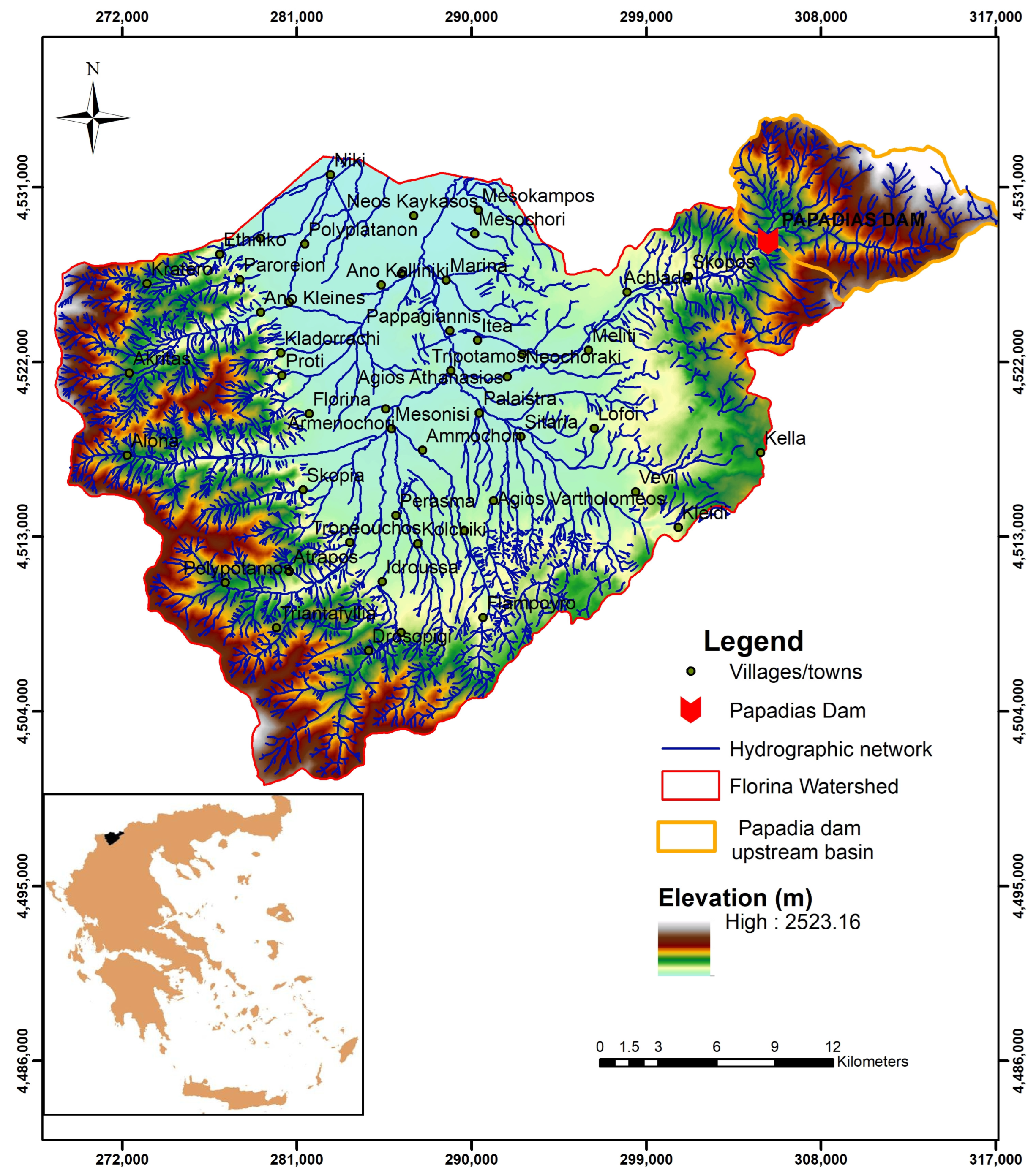
Figure 1. Topographic map of the Florina basin.
Water 15 00994 g001
Figure 2. Land cover of the Florina basin.
Water 15 00994 g002
Figure 3. View of the Papadia dam. (a) View of the dam from downstream. (b) View of the reservoir from the dam crest. (c) View of the spillway from downstream.
Water 15 00994 g003
Figure 4. Methodological approach of the Papadia dam breach analysis.
Water 15 00994 g004
Figure 5. View of the channel riverbed downstream of Papadia dam.
Water 15 00994 g005
Figure 6. Final dam breach geometry plot (overtopping).
Water 15 00994 g006
Figure 7. Final dam breach geometry plot (piping).
Water 15 00994 g007
Figure 8. Two-dimensional flow area downstream of Papadia dam.
Water 15 00994 g008
Figure 9. The PMF for the Papadia dam catchment.
Water 15 00994 g009
Figure 10. Maximum discharge on the dam breach structure for varying breach parameters.
Water 15 00994 g010
Figure 11. Time of occurrence of the maximum discharge on the dam breach for varying breach parameters.
Water 15 00994 g011
Figure 12. Maximum water depth for varying breach parameters..
Water 15 00994 g012
Figure 13. Maximum water depth and boundaries of inundated area in the case of overtopping dam failure.
Water 15 00994 g013
Figure 14. Maximum water depth and boundaries of inundated area in the case of piping dam failure.
Water 15 00994 g014
Figure 15. Maximum water velocity and boundaries of inundated area in the case of the overtopping dam failure.
Water 15 00994 g015
Figure 16. Maximum water velocity and boundaries of inundated area in the case of the piping dam failure.
Water 15 00994 g016
Figure 17. Flood hazard maps for the overtopping dam failure scenario (first classification approach).
Water 15 00994 g017
Figure 18. Flood hazard maps for the piping dam failure scenario (fist classification approach).
Water 15 00994 g018
Figure 19. Flood hazard maps for the overtopping dam failure scenario (second classification approach).
Water 15 00994 g019
Figure 20. Flood hazard maps for the piping dam failure scenario (second classification approach).
Water 15 00994 g020
Table 1. Florina hydrological basin land cover (CORINE 2018).
Land CoverArea (km2)%
Discontinuous urban fabric6.150.71
Industrial/commercial units3.150.36
Mineral extraction sites2.970.34
Non-irrigated arable land307.3335.61
Pastures7.360.85
Complex cultivation patterns21.782.52
Land occupied by agriculture/natural vegetation94.3810.94
Broad-leaved forest241.0827.94
Coniferous forest5.730.66
Mixed forest8.701.01
Natural grasslands72.898.45
Sclerophyllous vegetation15.681.82
Transitional woodland–shrub75.738.78
Table 2. Papadia dam technical characteristics.
ParameterValue
Crest elevation (m a.s.l.)933
Crest length (m)538
Crest width (m)12
Maximum height of dam from foundation (m)67
Volume of storage area at crest elevation (×106 m3)14
Upstream dam face slope2:1
Downstream dam face slope1.8:1
Spillway maximum capacity (m3/s)420
Spillway crest elevation (m a.s.l.)928
Spillway width (m)35
Table 3. Manning roughness coefficient values according to land cover.
Land CoverManning Coefficient (n)Reference
Cultivated areas 0.030–0.04/0.035[44]/[45]
Forests0.1/0.16[46]/[47]
Natural Minor Streams on plain 0.035[44]
Discontinuous urban fabric0.013[46]
Residential area (low intensity)0.05[47]
Pastures0.030–0.035/0.03[44]/[46]
Table 4. Breach parameters for the dam failure mode.
Breach Parameters and DataDam Failure Mode
OvertoppingPiping
Manning’s n value0.035 s m−1/30.035 s m−1/3
Storage area volume13.0 × 106 m313.0 × 106 m3
Final bottom width25 m23 m
Final bottom elevation+880 m a.s.l+880 m a.s.l.
Left side slope10.7
Right side slope10.7
Weir coefficient for breach area1.441.44
Breach formation time0.38 h0.38 h
Trigger failure at water surface elevation (starting water surface)+933 m a.s.l.+933 m a.s.l.
Table 5. Flood severity classes (first classification approach).
Flood Severity CategoryDepth*Velocity Range (m2/s)
Low<0.2
Medium0.2–0.5
High0.5–1.5
Very High1.5–2.5
Extreme>2.5
Table 6. Critical simulation outputs of the dam failure scenarios.
OvertoppingPiping
Maximum discharge on the dam breach structure13,365 m3/s10,800m3/s
Maximum discharge on the outlet of the 2D flow area673.3 m3/s266.2 m3/s
First arrival time of flood water on the outlet of the 2D flow area (after the beginning of failure)216 min270 min
Arrival time of maximum discharge on the outlet of the 2D flow area (after the beginning of failure)279 min319 min
Maximum flood water depth30.75 m29.2 m
Maximum flood water velocity21 m/s20.5 m/s
Table 7. Mesh size sensitivity analysis results.
Simulation Outputs for Mesh Size SensitivityMesh Size
25 × 2550 × 50100 × 100
Maximum discharge on the outlet of the 2D flow area (m3/s)673.3617.48
(−8.3%)
614.77
(−8.7%)
Arrival time of maximum discharge on the outlet of the 2D flow area (min)279272
(−2.5%)
258
(−7.5%)
Maximum flood water depth (m)30.7529.3
(−4.7%)
22.9
(−25.5%)
Table 8. Flood severity classes for maximum water depth and the inundated area per class.
Flood
Severity Category
Max Depth (m)OvertoppingPiping
Area (km2)Area
(%)
Area (km2)Area
(%)
Low/Medium0–317.7370.8916.9573.17
High/Very High3–65.4421.764.7520.51
Extreme>61.837.351.466.32
Total Area:25.0110023.16100
Table 9. Flood severity classes for maximum water velocity and the inundated area per class.
Flood
Severity Category
Max
Velocity (m/s)
OvertoppingPiping
Area (km2)Area
(%)
Area (km2)Area
(%)
Low/High0–213.6854.6913.2057.00
Very High/Extreme>211.3345.329.9643.00
Total Area:25.0110023.16100
Table 10. Flood severity classes for the product of water depth and velocity and the inundated area per class (first classification approach).
Flood
Severity Category
Depth*Velocity Range (m2/s)OvertoppingPiping
Area (km2)Area
(%)
Area (km2)Area
(%)
Low<0.24.3317.314.7620.55
Medium0.2–0.52.459.803.0313.08
High0.5–1.55.1420.553.8316.54
Very High1.5–2.51.987.921.868.03
Extreme>2.511.1144.429.6841.80
Total Area:25.0110023.16100
Table 11. Flood severity classes for the product of water depth and velocity and the inundated area per class (second classification approach).
Flood
Severity Category
Depth*Velocity Range (m2/s)OvertoppingPiping
Area (km2)Area
(%)
Area (km2)Area
(%)
Low0–0.88.8835.519.7141.93
High>0.816.1364.4913.4558.07
Total Area:25.0110023.16100
Table 12. Inundated area per land cover for the overtopping scenario.
Land CoverArea (km2)Area (%)
Discontinuous urban fabric0.682.72
Non-irrigated arable land15.6462.52
Complex cultivation patterns5.3021.19
Land occupied by agriculture or natural vegetation2.5310.11
Broad-leaved forest0.0040.02
Mixed forest0.411.64
Pastures0.040.16
Sclerophyllous vegetation0.150.60
Transitional woodland/shrub0.261.04
Total Area:25.01100
Disclaimer/Publisher’s Note: The statements, opinions and data contained in all publications are solely those of the individual author(s) and contributor(s) and not of MDPI and/or the editor(s). MDPI and/or the editor(s) disclaim responsibility for any injury to people or property resulting from any ideas, methods, instructions or products referred to in the content.