Article

Analysis of the Effect of Pore Water Pressure on a Small Radius Curve Section of a Fine Sand Layer under Cyclic Metro

1
College of Geosciences and Engineering, North China University of Water Resources and Electric Power, Zhengzhou 450046, China
2
Guangzhou Metro Design & Research Institute Co., Ltd., Guangzhou 510010, China
3
School of Earth Sciences, China University of Geosciences, Wuhan 430079, China
*
Author to whom correspondence should be addressed.
Water 2023, 15(5), 981; https://doi.org/10.3390/w15050981
Submission received: 7 December 2022 / Revised: 26 February 2023 / Accepted: 28 February 2023 / Published: 3 March 2023
(This article belongs to the Section Soil and Water)

Abstract

:
Small curved metro shield tunnels located in fine sand layers are sensitive to the response of horizontal and vertical cyclic loads from train operations, especially for centrifugal horizontal loads. The majority of Zhengzhou’s strata are dominated by this geological composition. Therefore, the dynamic response of the fine sand layer under the train vibration load will lead to the settlement of the sand layer, which brings great hidden danger to the train operation. Long-term pore water monitoring was carried out in this paper, and the use of MIDAS-GTS (Multi-candidate Iterative Design with Adaptive Selection) finite element calculation platform to establish the metro ballast-lining-soil coupling dynamic model for mutual verification. The variation patterns of pore water pressure and super pore water pressure during train operation and the vibration response pattern of the soil layer around the tunnel were investigated. The results suggest that: (1) The pore and excess pore water pressures generated at the start of vibration are not easily dissipated and transferred, making them larger in the early stages of train operation. In contrast, the fine-grained powdered sandy soil has a small amount of clay particles, giving strength and cohesion to the soil layer. Vibrating hole pressure and excess pore water pressure stabilize with the train at a later stage; (2) The low probability of liquefaction in the silt layer surrounding the tunnel; (3) Under vibrating loads, areas of significant soil settlement are concentrated on the soil surface, on the upper side of the tunnel in the silty sand layer and at the bottom 3 m of the tunnel, however, its low variation in settlement has a low impact on the tunnel.

1. Introduction

The rapid development of the metro has brought convenience to people’s lives and at the same time, due to the vibrations caused by its operation and the deformation of the soil caused by the increase in operating time, the problem has attracted a high degree of attention. The main factors affecting the deformation of the soil layer around the metro tunnel are the long-term effect of cyclic train loads, the effect of adverse engineering on geological conditions, the growth and dissipation of pore pressure and the influence of other surrounding engineering construction [1,2,3]. The vibration load generated by the operation of the underground is a special cyclic load different from the static load, and the response of the fine sand soil layer is more sensitive to this special cyclic load, which may lead to an increase in the pore water pressure of the soil around the tunnel, and even cause local soil liquefaction phenomenon [4,5,6]. The liquefaction of sandy soils under vibration causes a significant reduction in the strength of the soil until it is lost. At present, the main methods for determining liquefaction are the effective stress method, i.e., the pore pressure in the sand foundation gradually rises, while the effective stress gradually decreases, resulting in the deformation of the structure reaching or exceeding the permissible deformation; the shear stress resistance to liquefaction method (SEED method), i.e., The liquefaction of a sand soil if the shear strength (CRR) > the equivalent cyclic stress ratio (CSR) underground vibration loading, and vice versa, and the shear wave velocity method, i.e., the shear wave velocity of the soil material is compared with the shear wave velocity of the soil in the liquefied state to determine whether the soil is liquefied or not in the actual project, and if the measured wave velocity is large, the soil is not liquefied, and vice versa [7,8]. Zhengzhou is located in the middle and lower reaches of the Yellow River, and the powdered and fine sandy soils in the strata are more widely distributed, and that type of soil are more susceptible to vibration damage than the soft clay soils at the beginning of metro operation. In particular, small radius curved tunnels have a more significant impact on the surrounding environment in terms of soil deformation, groundwater infiltration and the stability of adjacent buildings than straight tunnels [9,10,11]. In response to these problems, pore water pressure changes in soils under cyclic train loading and the development of soil deformation have received widespread attention from academic and engineering circles [10,11,12,13].
The indoor cyclic triaxial test method can be used to study the dynamic cumulative deformation properties of soils under vibratory loads. Quiyang et al. [14] developed a mathematical model-based pore water pressure model based on laboratory test of saturated silty soils under low-frequency cyclic loading and found that the key factor affecting pore water pressure was cyclic stress, followed by loading frequency and finally consolidation. Cary et al. [15] investigated the pore water pressure response of soils under vibrational loading in saturated and unsaturated conditions through triaxial tests and proposed a model capable of predicting cumulative excess pore water pressure under saturated and unsaturated conditions. Castelli et al. [16] analysed the variation of coarse-grained soil shear modulus and damping ratio with depth using cyclic triaxial experiments, concluding that the soil behaviour should be elastic at very small strains and that the periodic degradation of the soil causes a decrease in stiffness, an increase in damping ratio and an increase in pore water pressure as cyclic stresses increase. Porcino [17] conducted a study using undrained cyclic simple shear (CSS) tests to predict whether super-pore water pressures during cyclic vibratory loading can cause liquefaction of pulverized soils. Karakan et al. [18] assessed the post-liquefaction cyclic behaviour of finitely liquefied (pore water pressure ratio-Ru < 0.5) silts using cyclic triaxial compression tests on the basis of the proximity of the material pore ratio to the critical pore ratio as the basis for the occurrence of finite liquefaction, and considered the super-pore water pressure due to cyclic loading (double cycling) and its effect on the undrained dynamic behaviour of the chalk sand under sinusoidal loading -whether the chalk sand is subject to finite liquefaction, demonstrating that the specimen will undergo finite liquefaction when its pore ratio is close to or greater than a critical value. Junhui et al. [19]. analysed the dynamic response of soils by shear modulus equation and dynamic triaxial experiments and settlement prediction, and found that by increasing the dynamic load frequency, the load time acting on the soil was shorter, soil deformation was reduced, and dynamic shear modulus increased. Although there are many current research results on triaxial testing of the dynamic response of soils under vibratory loads, most relate to seismic loading. Numerous studies have shown that the generation of excess pore pressure requires a minimum stress threshold for liquefaction, and if this threshold is not reached, then liquefaction cannot be avoided by the number of vibration cycles experienced by the soil.
In order to take into account the full range of effects of train vibrations on the dynamic properties of the tunnel structure and the surrounding soil, researchers have deployed electronic equipment or precision instruments at engineering sites to verify the accuracy of theoretical considerations and numerical models. The results of measurements on built or trial structures are used, which is of great significance in verifying the reasonableness of the calculation results of numerical models [19,20,21]. For example, Tang [22] and others carried out continuous multi-period monitoring by means of pressure sensors buried at the engineering site and studied the variation of dynamic response frequency and stress amplitude with soil depth in soft clay soils under the action of vibrating train loads; Shiping et al. [23] studied the pore water pressure growth and dissipation change law under the vibration load of the underground by means of on-site monitoring of pore water; Wang et al. [24] studied and analysed the long-term cumulative deformation development law and soil dynamic response characteristics of the powder-fine sand layer under the vibration load of the train, taking the Nanjing underground as an example; Xu et al. [4] used the numerical simulation software ADINA (Automatic Dynamic Incremental Non-linear Analysis system) and model experiments to analyse the variation of pore water pressure in the soil layer at the bottom of the tunnel section of the Beijing underground and to predict the settlement caused by the cyclic underground loading; Xiao et al. [25] investigated the effect of train vibration loads on the settlement of soil around the tunnel at different speeds and small curve radii by means of the finite element calculation platform MIDAS in a pulverized fine sand soil layer. Wei et al. [26] analysed the settlement of buildings caused by the construction of small radius curve tunnels by combining field monitoring and numerical simulation and derived an analytical expression for the pore water pressure distribution in the soil surrounding the tunnel.
In summary, the effect of train vibration load on soil deformation has received attention from scholars [27,28,29,30,31,32,33], but most of the research objects are straight tunnels, while curved tunnels are rarely studied, and most of them are based on model experiments, establishment of pore pressure models or numerical simulations. There is a lack of verification and analysis of actual measured pore pressure data with numerical calculation results. This paper presents a field test on the dissipation of pore water pressure growth in the lower lying soil layer caused by underground vibration in a small radius curve section, and studies the response characteristics of pore pressure to vibratory loads. It establishes a coupled dynamic model of the metro ballast-lining-soil using reliable dynamic parameters obtained from experimental interval exploration data. The study of the development of soil deformation around the tunnel in this section will provide theoretical support and scientific basis for other metro shield intervals.

2. Materials and Methods

2.1. Experimental Design

2.1.1. Experimental Site Overview

The experimental site is located in the shield interval between South Agriculture Road Station and South Dongfeng Road Station of Zhengzhou Metro Line 1. According to the regional geological data and the preliminary exploration and drilling of the adjacent work area, the landform in this area is the alluvial flat of the Yellow River. Through geological exploration within the depth range of 50.0 m below the strata, the outcrops in Zhengzhou are all Quaternary strata, deposited from lower Pleistocene to Holocene. The total thickness of the strata is 50–200 m, from southwest to northeast. The strata are thickened from thin strata, and are in unconformable contact with the underlying Tertiary strata. The lithology of the strata in the area is mainly: Quaternary Holocene (Q4) strata at a depth range of 30 m, silt (slightly dense to medium dense) and silt clay with silty sand and fine sand at a depth range of 0–20 m, and medium dense to dense fine sand at a depth range of 20–30 m. The strata at a depth range of 30–50 m are mainly Quaternary Upper Pleistocene (Q3) silty clay (plastic—hard plastic) and silty sand (dense), mainly yellowish brown with minor calcium cores and iron rust flecks. According to the regional geological data and the existing engineering geological data, the physical and mechanical properties of each soil layer are shown in Table 1.
The tunnel is mainly located in silty clay, silty sand, and medium sand strata. The closer to the tunnel, the greater the dynamic response characteristics of the soil. The area has now caused 60–80 mm settlement under the cyclic loading of trains. The geological profile is shown in Figure 1. The burial depth of the groundwater table of the site ranges from 9.37–15.4 m, and the groundwater is mainly located in the silty clay, silty sand, and silt ground below about 9 m.

2.1.2. Experimental Measurement Point Layout

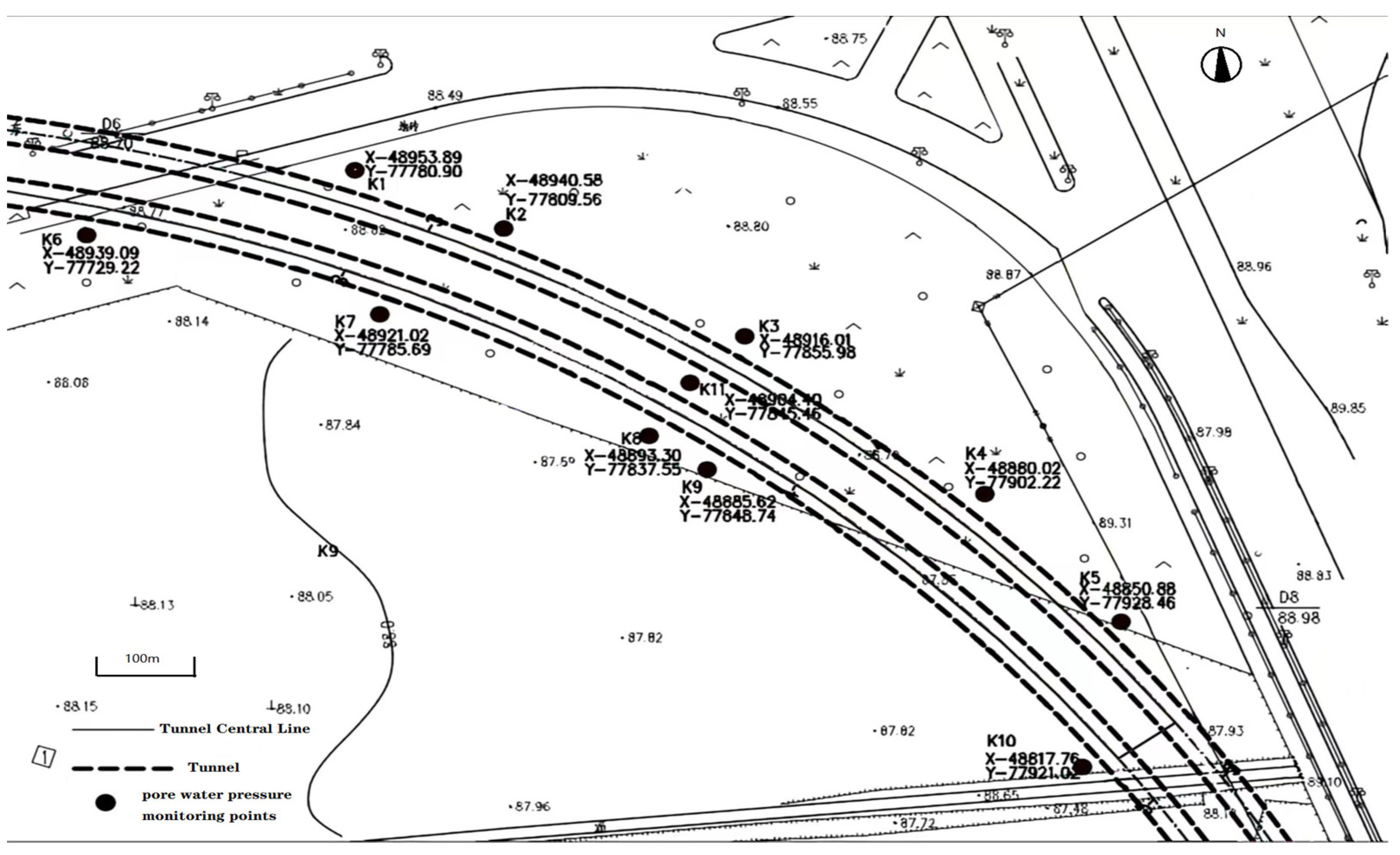
Since Line 1 has begun to operate, eleven points are arranged along the subway line on the same horizontal surface at the bottom of the tunnel in this experiment, and two points K3 and K11 were selected for layering according to the Pore Water Pressure Test Procedure (CECS55:93), and three additional vertical observation points were laid out each to obtain data from different depths and soil layers. According to the site survey, the plan of monitoring points is shown in Figure 2.

2.1.3. Experimental Content and Programme

Considering the characteristics of the soil around the metro tunnel and the influence of relevant factors such as train vibrations, ambient temperature, and the way in which the deformation of the structure is monitored and measured, there will be some deviation between the monitoring results and the actual values. The monitoring method therefore uses a combination of on-site manual observations and automated measurements, as shown in Table 2.

2.2. Field Data Analysis

2.2.1. Pore Water Pressure Response Analysis under Cyclic Loading

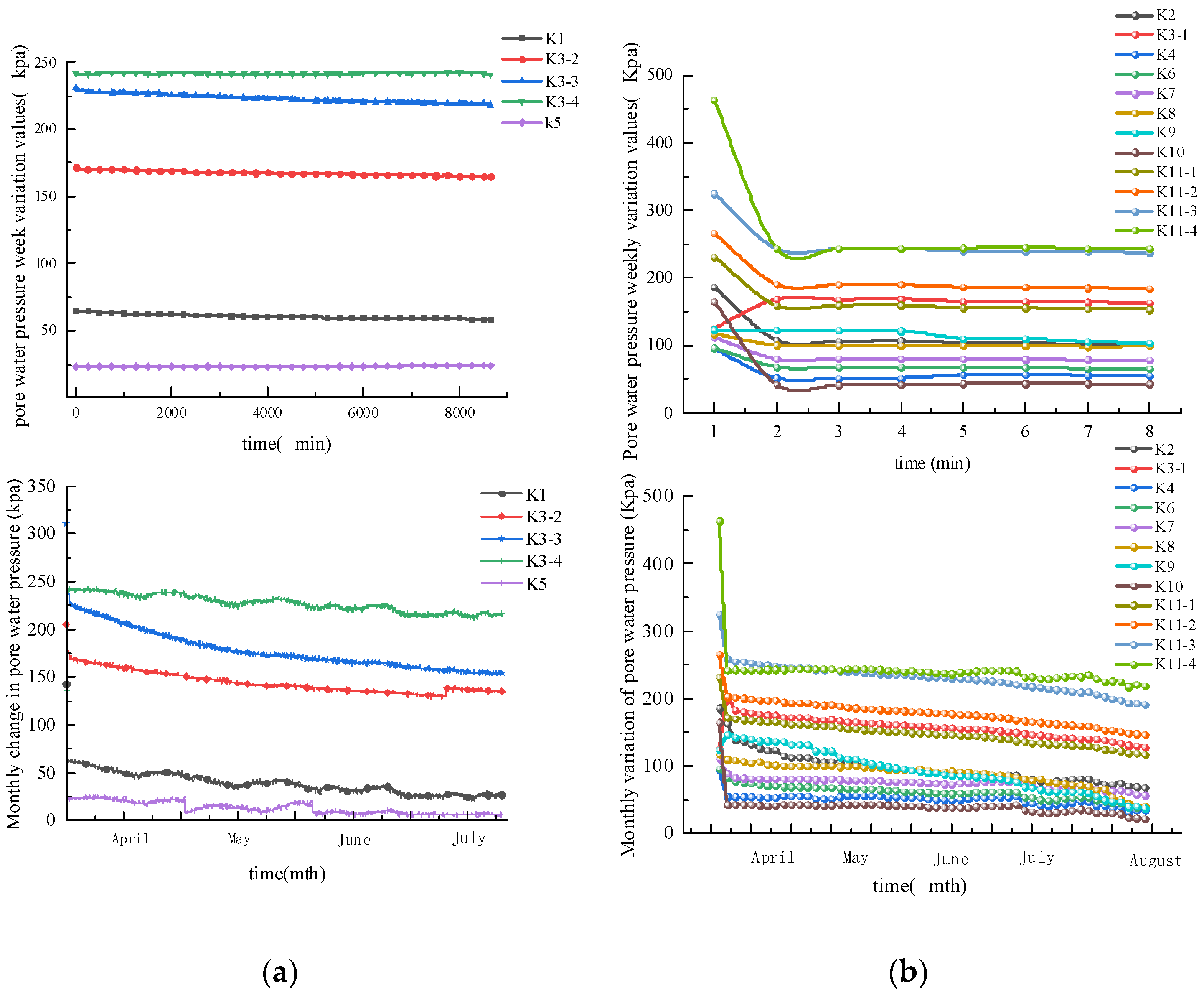
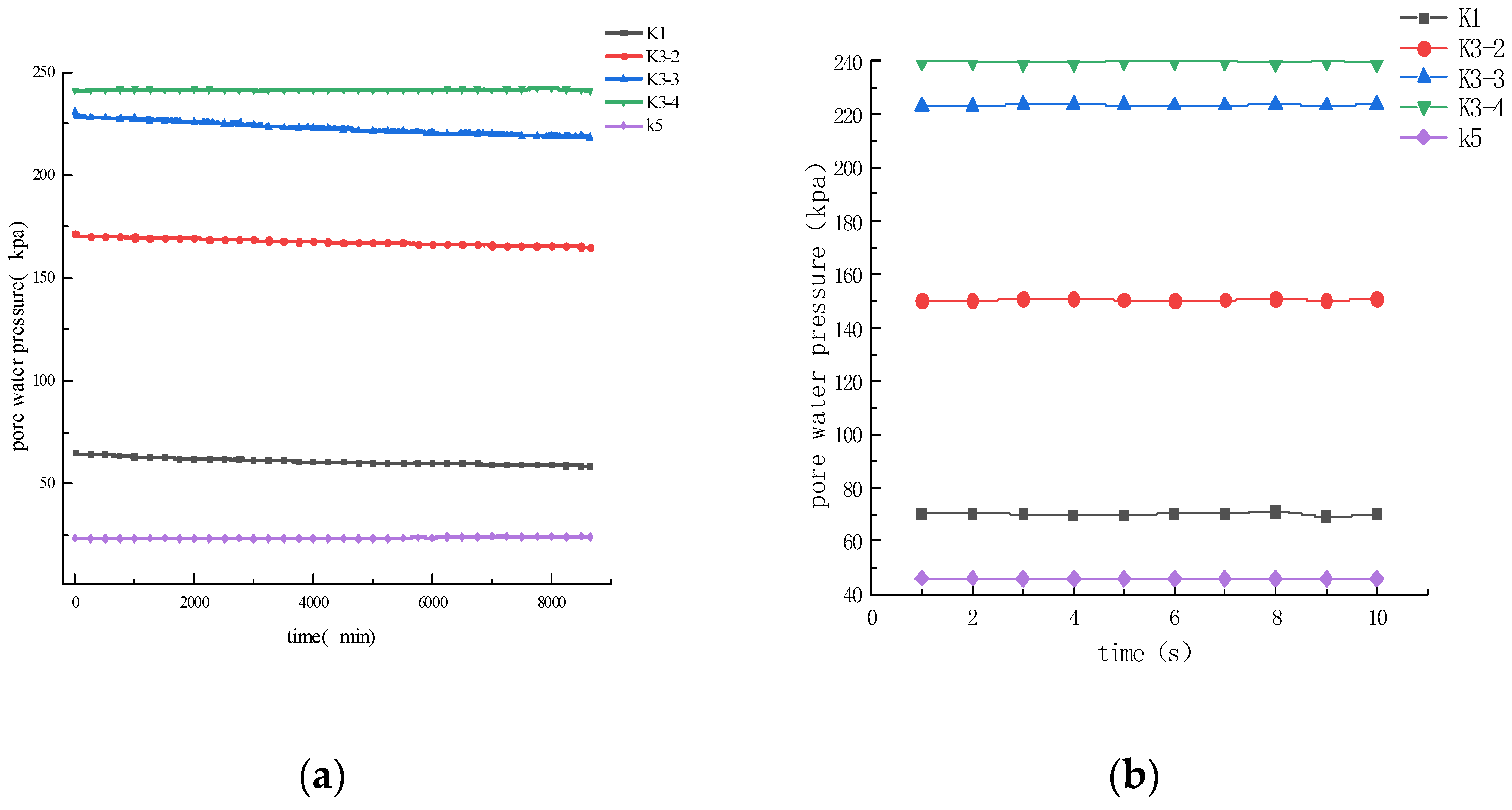
The cumulative pore pressure variation curves for each monitoring point under cyclic loading at different time periods are shown in Figure 3. Comparing the pore pressure variation curves at the automated and manual monitoring points, it can be seen that the amount of pore pressure variation at the automated monitoring points is relatively stable, and the pore water pressure shows an overall decreasing trend under the long-term effect of train loads.
The analysis of data collated from five automated and twelve manual monitoring sites showed that the pore water pressure fluctuates gradually with time under the cyclic train load, first increasing, then decreasing, then increasing and then decreasing again, taking into account the peak periods of morning, midday and evening commuting, the usual low periods and during the night when the trains are out of service, resulting in slight fluctuations in pore pressure. However, the fluctuations are around 0~1.04, which is not significant. The pore water pressure overall varies seasonally as the tunnel is subjected to continuous cyclic loading (5 months), with a significant drop in pore water pressure in the second quarter as temperatures gradually increase and rainfall decreases. The pore water pressure is expected to rise in the third quarter due to the flooding season. The higher pore pressure values at K3-4 and K11-4 compared to the other monitoring points are due to the deeper depth of burial (38 m) at this monitoring location. K2, K6 and K7 are at the same depth of burial but at different distances from the tunnel floor and different clear distances from the outer contour plane of the interval tunnel, and the closer they are to the tunnel, the higher the initial pore pressure values.
Figure 4 shows the pore pressure change curves for three time periods during the morning, midday, and evening peak periods. It can be seen that when the train load is applied, the pore water pressure rises rapidly within a short period of time. Each peak of the pore water pressure change curve corresponds to the wheel-rail excitation force generated by the train vibration, but there is a certain phase lag at 7:00 a.m. and around 19:00 p.m. The pore water pressure change amplitude is larger. After the train stops running (0:00–1:00) the pore water pressure starts to dissipate as the train load disappears. This is due to the fact that during the day the underground is in operation, which imposes a vibratory load on the subsoil, causing the pore water pressure to rise.

2.2.2. Variation of Pore Water Pressure with Depth of Burial

The metro train has 6 cars, is 118 m long and has a maximum speed of 80 km/h. During train operation, the pore water pressure gauges buried at different depths have different responses to changes in pore water pressure caused by metro vibrations.
As can be seen from the analysis in Section 2.2.1, the pore water pressure did not vary significantly over the week, so three monitoring points (K3-2, K3-3 and K3-4) at different depths of burial were selected to analyse the effect of pore pressure variations on the soil lying under the tunnel over the course of the day, as shown in Figure 5.
Figure 5 shows an example on 4.20. The train started running at 06:04 on the same day and arrived at the monitoring point at approximately 06:17–06:20. The monitoring point (k3-2) at a depth of 23 m fluctuates slightly with the application of vibration loads from the train, and the pore pressure gradually decreases at night after the train stops running at 23:00. The monitoring point (K3-3) with a burial depth of 28 m had a rapid generation and sharp rise in pore pressure within a short period of time, with fluctuations in line with the frequency of train vibration, and after the train stopped running, the pore pressure did not drop sharply but remained stable. The pore pressure rises slowly with time at a depth of 38 m (K3-4), which shows that the pore pressure is not easily dissipated in the short term when the tunnel subsoil is under vibratory train loads.
To sum it up, it can be concluded that the response of the silt sand around the tunnel to train vibration under cyclic train loading is closely related to the location. The closer to the tunnel, the more sensitive the response is. After the upper part of the tunnel arch waist exceeds a certain depth range, the pore pressure decreases rapidly with the disappearance of the vibration force. The pore pressure of the soil layer under the tunnel arch waist with the disappearance of the vibration effect is not easy to dissipate in the short term.

2.2.3. Excess Pore Water Pressure Response Analysis

Under the action of vibrating train loads, due to the small permeability [34] of the silty sand and the short duration of the load action before it can be drained, the super-pore water pressure in the soil will increase, further leading to an increase in pore water pressure, further leading to an increase in pore water pressure. It therefore becomes important to analyse the changes in excess pore water pressure under vibrating train loads.
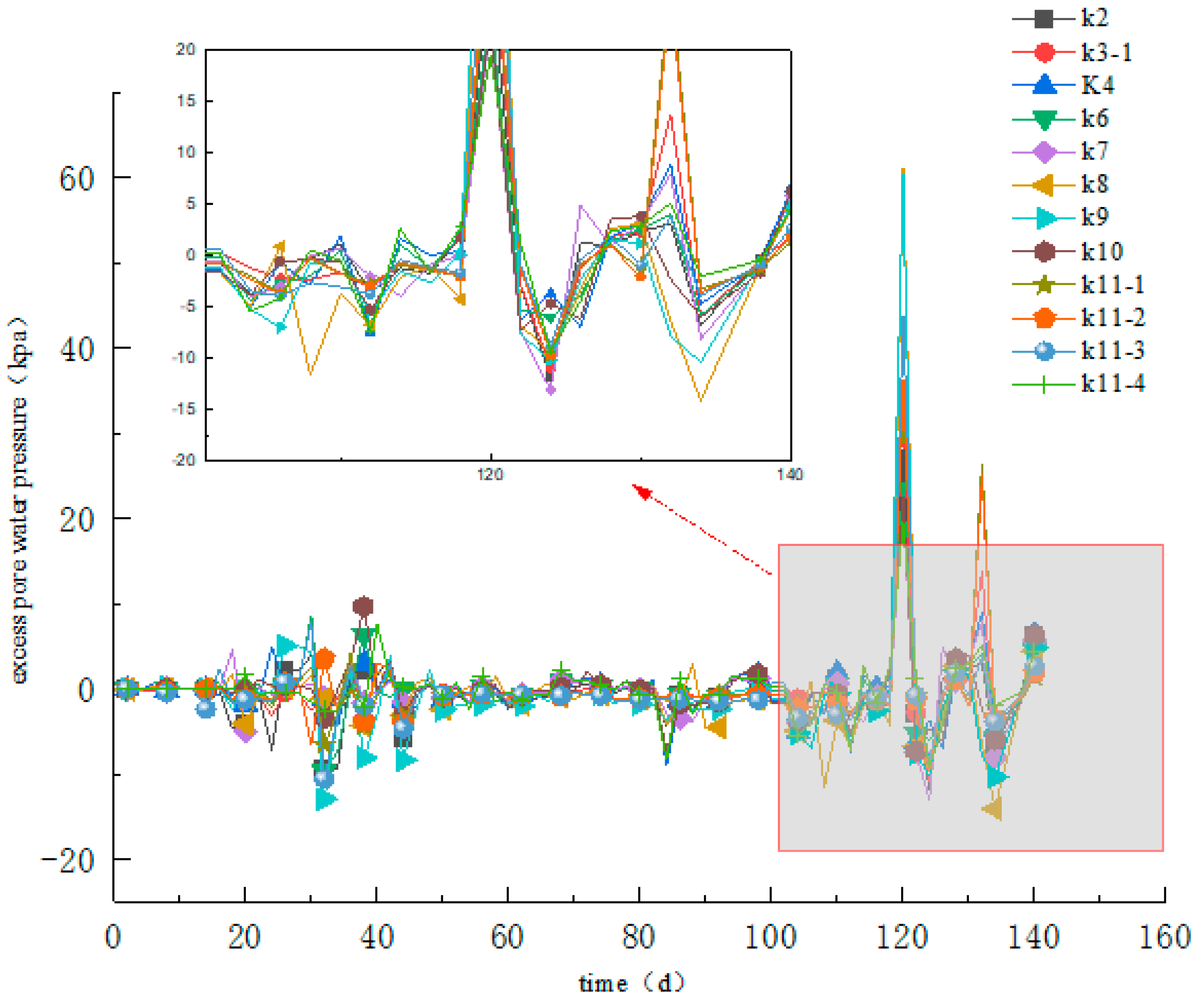
Figure 6 shows the variation curve of excess pore water pressure at the manually monitored points under cyclic loading. This is manifested by the rapid generation and dramatic increase in excess pore water pressure within a short period of time after the application of a vibrating train load. It can be seen that the difference between the monitored values and the hydrostatic pressure values (excess pore water pressure) generated by the detected difference in water level elevation at the 12 manually monitored points is small, and can be seen to be basically within 0.7 kpa most of the time, with the exception of the K9 monitoring point and the points that sometimes generated larger excess pore water pressures half a month ago. Around July 19 to 24, the rise in excess pore water pressure is due to the heavy rainfall situation in Zhengzhou, as shown in Figure 6 to magnify most of it (this study is not executed in this paper), so the excess pore water pressure will rise. The excess pore water pressure variation curve over a 6-month period shows that the excess pore water pressure gradually dissipates over time under cyclic loading. It can be seen that the pore pressure and excess pore pressure are larger at the beginning of train operation and gradually stabilize at the later stage, which is due to the fact that the pore water pressure generated at the beginning of train vibration is not easy to dissipate and transfer back to produce a larger body variation potential, resulting in a rapid increase in the initial pore pressure value. However, due to the fine particles of powder fine sand soil, there will be a small amount of clay particles, so that the soil layer has a certain structural strength and cohesion, which limits the further increase in the body variation potential, resulting in a slower growth of the pore pressure at the later stage until it tends to stabilize [34].

2.2.4. Ground Settlement Monitoring Analysis

In order to study the variation of the vertical displacement of the metro line bed over time under vibrating train loads, a Trimble DiNi03 electronic level (accuracy 0.3 mm/km) was used to make on-site observations of the vertical displacement of the bed. After the observations were completed, the instrument was connected to a computer to import the observed data, and the leveling software was used to level the data and obtain the elevation of each measurement point.
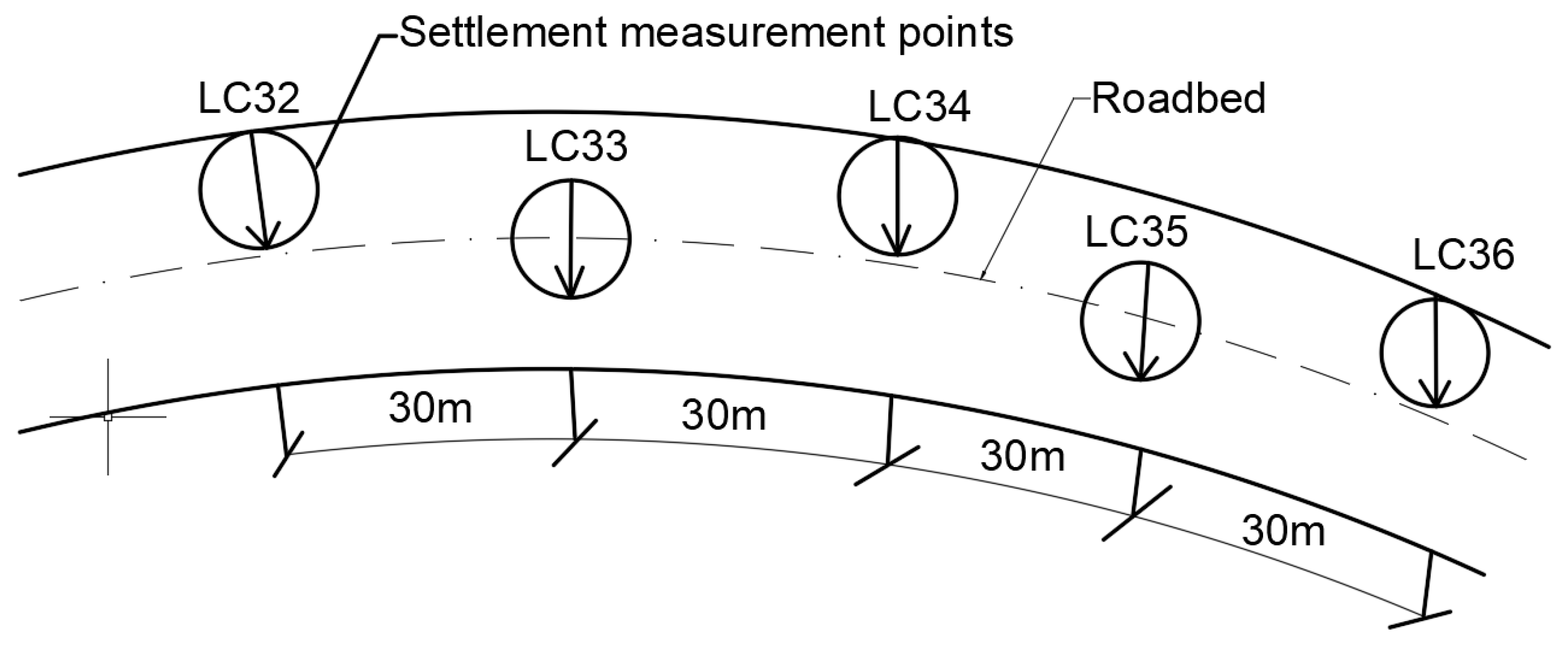
Vertical displacement monitoring points are buried in the road bed, one at each interval of 30 m, and the location of the monitoring points is shown in Figure 7.
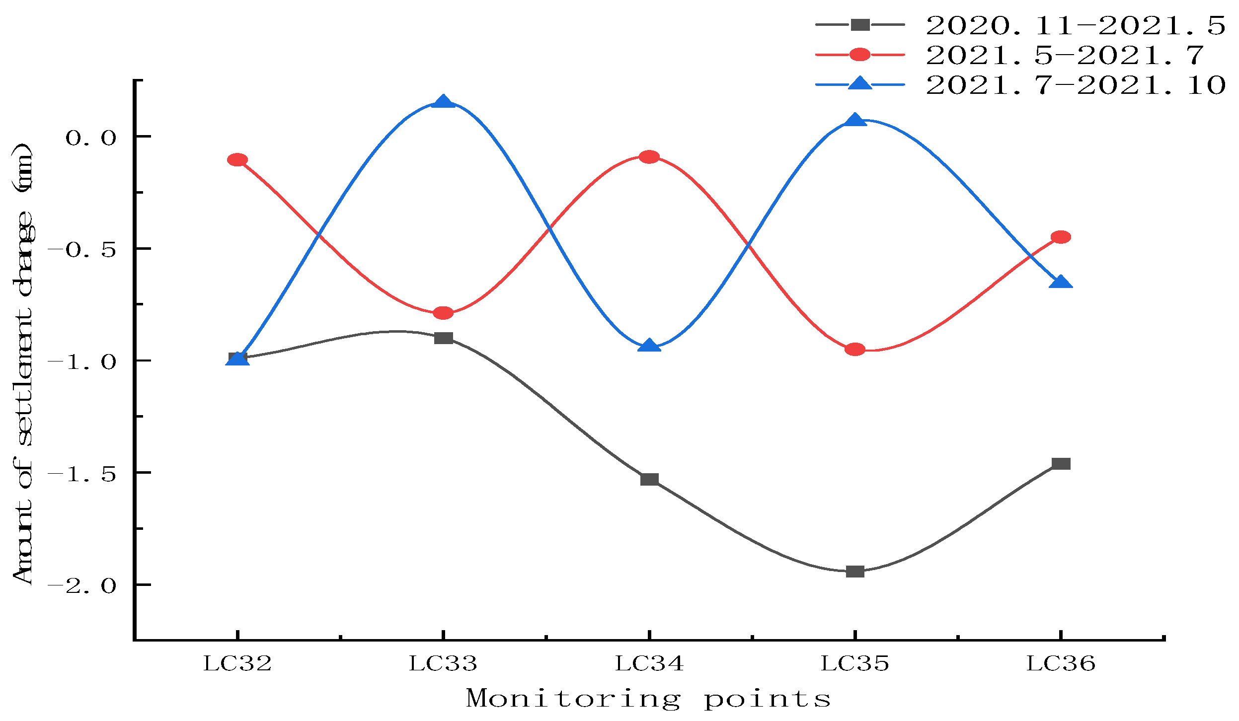
Figure 8 shows the settlement variation curve of the tunnel between November 2020 and October 2021 for the curved section of South Nongye Road—South Dongfeng Road, where the settlement variation between May 2021 and October 2021 corresponds to the pore pressure monitoring period. As shown in the diagram, the settlement of the curved tunnel reaches 2 mm in the early stage of the operation period, and the settlement deformation of the tunnel between the zones is obviously uneven, and gradually decreases to within 1 mm during the hole pressure monitoring period, indicating that the settlement of the tunnel gradually decreases and reaches stability under a certain number of train vibration loadings.

2.2.5. Liquefaction Predictions for Silty Soils

Accumulation and dissipation of excess pore water pressure in the soil is due to long-term vibratory loading of the underground. When the accumulation of excess pore water pressure is much greater than the dissipation, the pore water pressure will increase accordingly, even causing the possibility of local soil liquefaction. It is therefore important to study the changes in the soil under long-term vibratory loads in the metro.
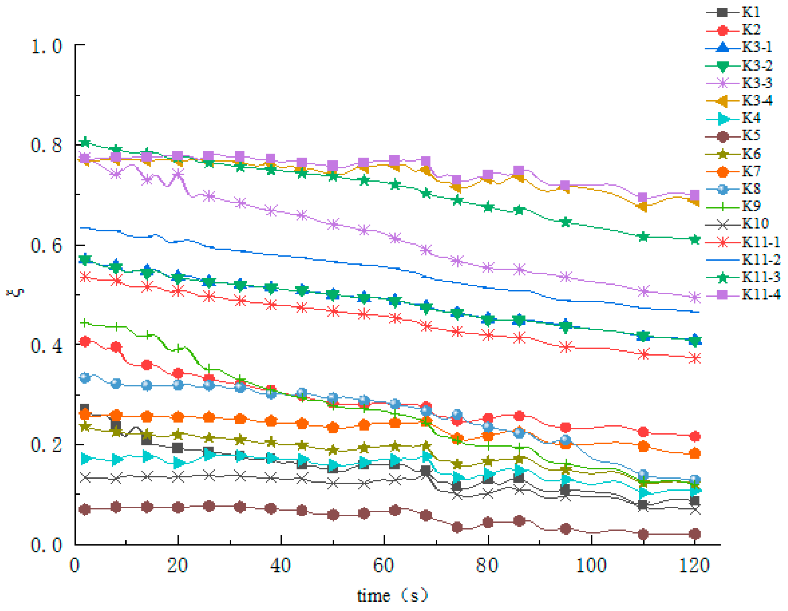
In order to analyse the liquefaction of the silty soils in the area, theoretical calculations were used to determine whether the sands were liquefied by comparing the ratio ( ζ ) of pore water pressure to total stress.
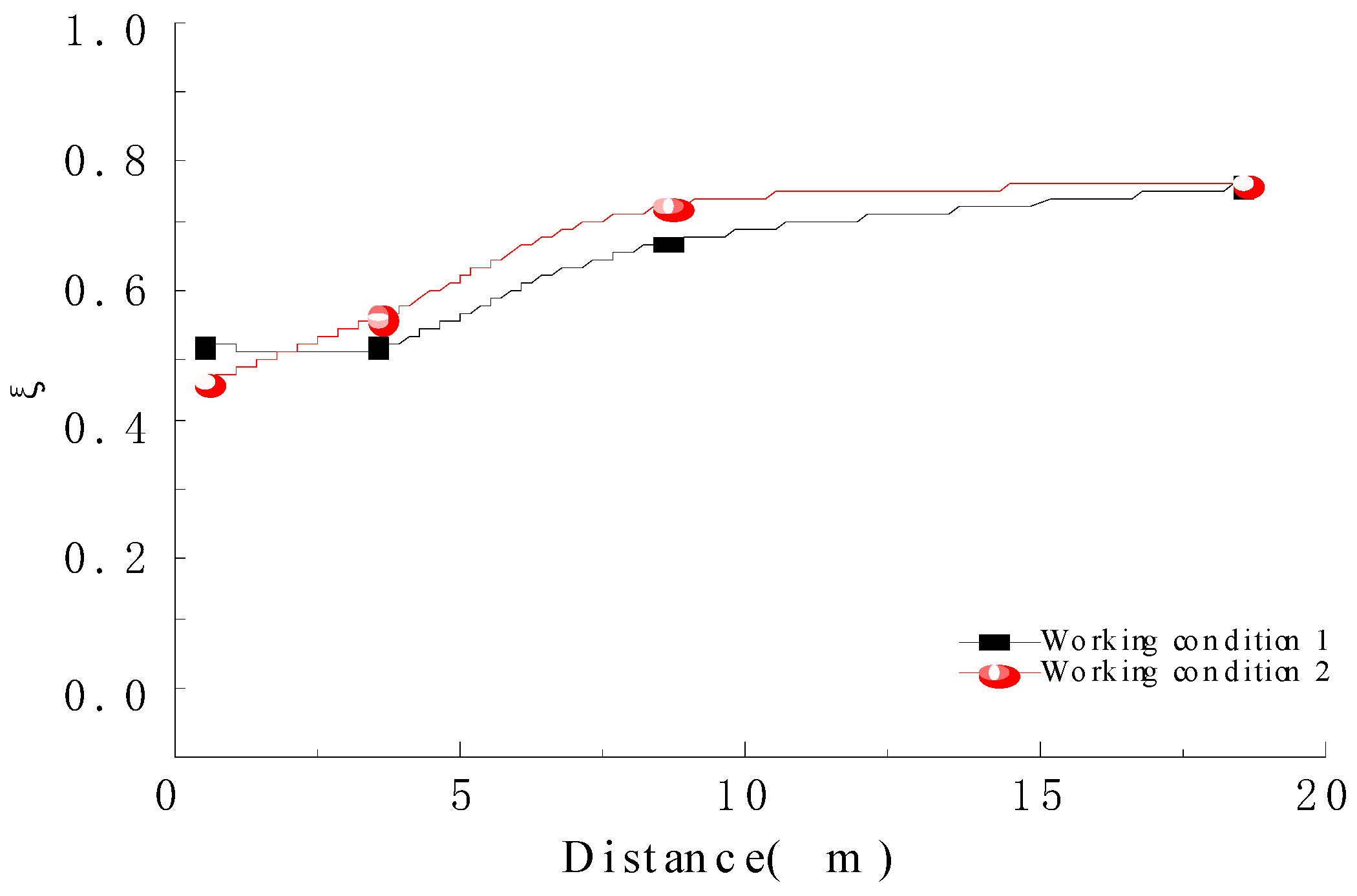
Assumptions ζ = μ σ , where μ indicates pore water pressure, σ indicates total stress. When the ratio ζ = 1 , the silty soil starts to liquefy; No liquefaction occurs when the ratio ζ < 1 . The curves of ζ values with time are shown in Figure 9 and Figure 10.
As can be seen in Figure 9 and Figure 10:
(1)
The ratio decreases under 0.8 for all monitoring points with increasing time, and the ratio decreases with increasing time for monitoring points with greater burial depths (e.g., K3-4, K11-4, K3-3, K11-3), indicating that the possibility of sand liquefaction is low.
(2)
Working conditions 1 and 2 represent K3-1 to K3-4 and K11-1 to K11-4, where the closer working condition 2 is to the tunnel, the greater the value found, which indicates that the closer to the tunnel the greater the dynamic response generated. At the same time, the ratio slowly increases and then decreases as the distance increases, remaining between 0.6 and 0.8, indicating that liquefaction is less likely to occur with increasing distance.

2.3. Constitutive Model

MIDAS-GTS is a finite element analysis software developed for geotechnical and tunnelling engineering, which enables the analysis of the response of complex models under static and dynamic loads, and is useful for studying the deformation of the soil underneath and around tunnels due to train vibrations. In order to study the deformation of the soil underneath and around the tunnel by train vibration, based on the field experiments, a coupled dynamic model of the metro ballast-lining-soil was developed using MIDAS-GTS.
The study of the dynamic response and deformation of weak soil layers under vibratory train loads has mostly been carried out using the Mohr-Coulomb elastoplastic principal structure model, and the results of the study are consistent with the measured values in the field [9]. Therefore, the three-dimensional finite element numerical model of the article adopts the Mohr-Coulomb model for the soil ontology and the linear constitutive ontology model for the tunnel structure.
The Mohr-Coulomb constitutive equation:
τ f = c + σ tan φ .
In the formula:
c —Soil bonding force
φ —The friction Angle in the soil
The shear strength is cohesive when the angle of internal friction is equal to 0. The shear strength of undrained soils is defined in the software as the cohesive strength of sandy soils, defined by = 0. If a cohesion value is defined, the program will calculate the tensile strength according to the defined cohesion value.
For cohesion increment reference heights:
c = c r e f + ( y r e f y ) c i n c ( y y r e f )
c = c r e f ( y > y r e f ) .
In the formula:
c r e f —Input cohesion values
c i n c —Incremental cohesion with depth
y r e f —Depth of measurement of cohesion c r e f
y indicates the position of the unit integral. If the integration position is higher than y r e f , the cohesive force may be smaller than 0. To avoid this, when the position of the integration point is higher than y r e f when the value of c r e f is chosen directly.
The angle of expansion can be seen as the rate of increase in volume of the shear strain. The angle of expansion for sandy soils changes with the angle of internal friction and must be set to 0 when the software performs an undrained analysis and the angle of internal friction is 0. If the angle of expansion is not taken into account, the angle of expansion is equal to the entered angle of internal friction. If the angle of expansion is not checked, the program will automatically consider the same angle of expansion as the angle of internal friction for the calculation.
Based on the groundwater level surveyed on site, the groundwater level is added to the finite element model, while the water pressure is automatically taken into account in the analysis control, and the program will obtain the pore pressure change after the train load is applied.
Once the chosen constitutive model has been determined, the physical mechanical parameters of the material need to be entered in the numerical model. In order to improve the practicality, flexibility and accuracy of the calculations, a number of assumptions are used, as follows:
(1)
It is assumed that all soil bodies in the same rock formation are elastic-plastic, isotropic materials and conform to the Moore-Coulomb yielding criterion.
(2)
The construction phase group, consolidation analysis module, performs initial ground stress calculations considering only the effect of self-weight stresses and ignoring the effect of tectonic stresses.
(3)
The train is considered to be running at a constant speed.

2.3.1. Numerical Model Development

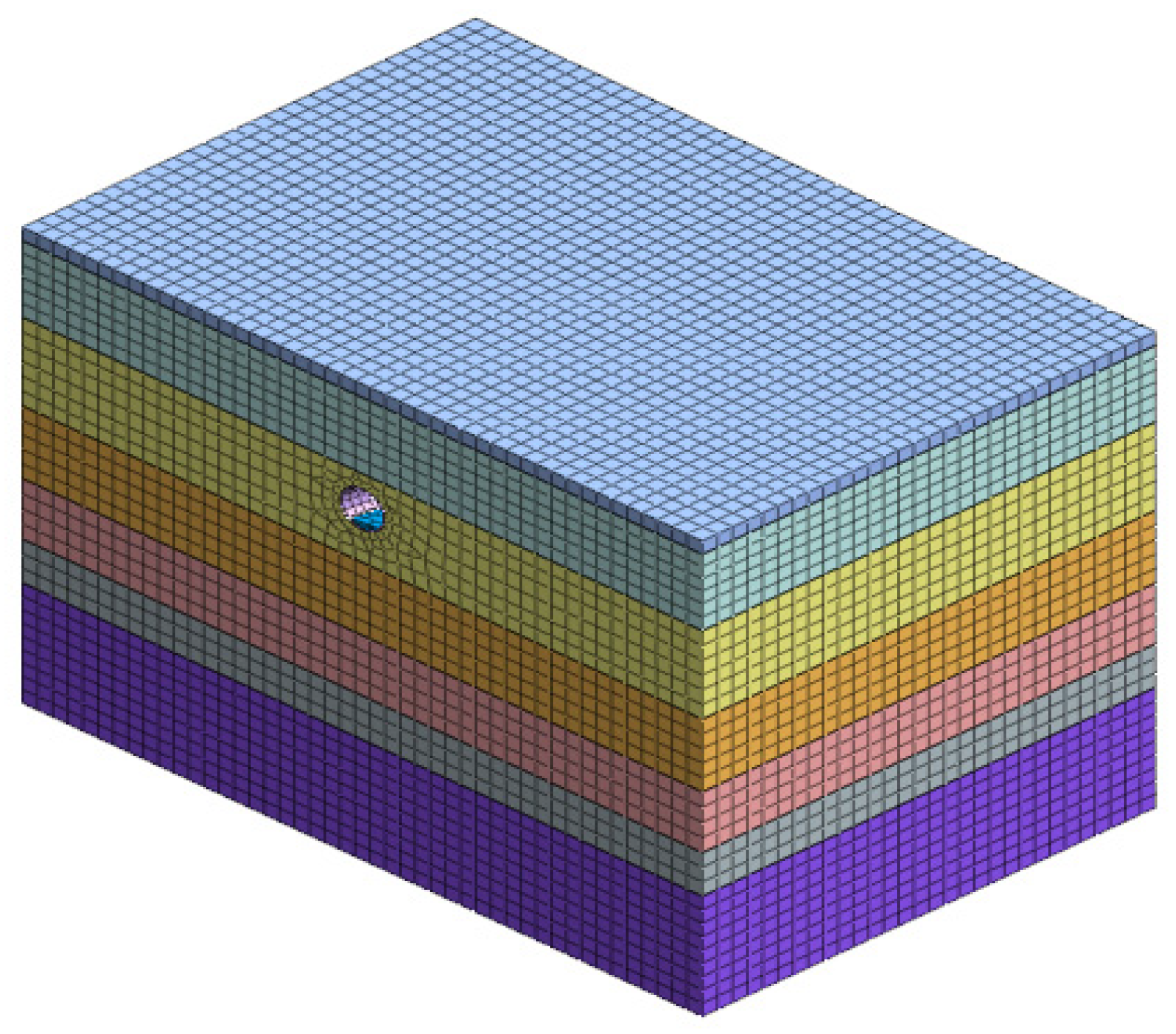
Before carrying out the calculations, it is first necessary to build a suitable model as shown in Figure 11. The vibration caused by the operation of the train is a semi-infinite spatial effect, as the curved tunnel is within 50 m of the tunnel axis in the horizontal direction and the horizontal vibration is 2 to 4 times stronger than the vertical vibration [35]. There are also help files from other finite element simulation software that suggest that calculation errors can be ignored when the cell size is 1/20th of the considered wavelength. According to the geotechnical profile in the tunnel section of the test interval of Zhengzhou Metro Line 1, the overall model dimensions of this paper are: 90 m × 60 m × 68.3 m (X × Y × Z). The tunnel is 7 m in diameter and 15 m deep. In order to make the model more accurate, the geometric model is finite element meshed and the mesh is divided using sparsity control. The closer to the tunnel axis, the more precise the mesh is, and vice versa.

2.3.2. Boundary Conditions and Model Parameters

(1)
Boundary conditions.
In order to obtain accurate results in a limited calculation area, fixed conditions are used at the bottom of the model, no constraints at the top, and free field boundaries all around. A drainage boundary is also set at the demarcation of each soil layer, and an impermeable boundary is set at the contact between the inner side of the tunnel lining and the soil. To avoid the waves and energy generated by the train vibrations being reflected back into the interior of the model, viscoelastic boundaries are used on both sides.
(2)
Model parameters
A three-dimensional numerical model of the coupled roadbed-tunnel-soil was developed based on the finite element software MIDAS. The simulated soil parameters are given in the geological survey report, and the soil layers in the study area are simplified into seven layers by weighted average of thickness, which are used as the soil layer parameters for the numerical model. Detailed soil parameters are shown in Table 3 below.

2.3.3. Determination of Vibration Loads

According to the B-type train selected for Zhengzhou metro line 1 and the metro design specification GB50157-2013 [36], this paper considers the highest running speed and full train load and divides the train load into vertical and horizontal loads and the centrifugal force caused by the track super-elevation [37] applied to the roadbed. According to the MIDAS numerical simulation software, the train load is applied to the roadbed to obtain the train vibration load curve for 5 s at the tunnel turning radius R = 350 m, as shown in Figure 12.

2.3.4. Calibration of the Model

Model reliability verification was analysed by inputting soil geomechanical parameters and applying train movement loads via MIDAS software.
According to the simulation results of the underground bed-lining-soil coupled dynamic model, the simulated values of pore water pressure are shown in Figure 13. The simulation results of the numerical model are similar to the change trend of the measured results, indicating that the numerical model can good reflect the pore water pressure growth and dissipation of the underlying soil layer caused by the underground vibration.

3. Results and Discussion

3.1. Excess Pore Water Pressure Response Pattern of the Soil at the Bottom of the Tunnel

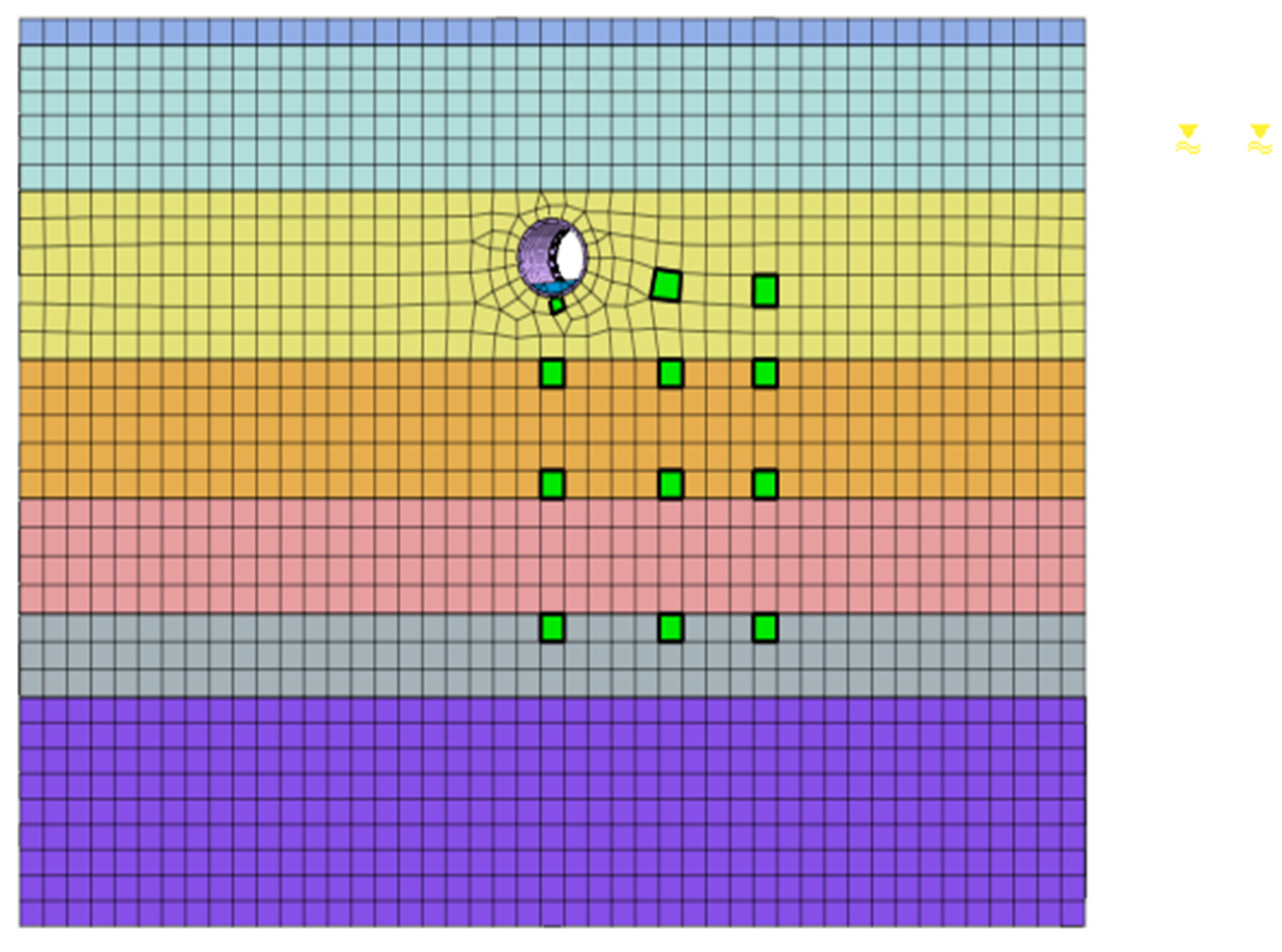
In order to analyse the excess pore water pressure response of the soil around the tunnel, data from a train vibrating for 15 min (3 cycles) were selected for analysis. The cells below the tunnel were selected at depths of 0.5, 5, 10, and 25 m and at horizontal distances of 0, 5, and 15 m from the tunnel. The locations of the cells are shown in Figure 14 below.
Without considering temperature and groundwater level, the calculations show that the excess pore water pressure decays more slowly with the greater horizontal distance from the tunnel as the metro train passes through the tunnel in three cycles. The trend of excess-pore pressure growth shows that the excess-pore pressure rises sharply as the train passes through a particular cell. After the train has passed, the excess pore pressure gradually decays under consolidation. The increase in excess pore water pressure under cyclic train loading is phased, as shown in Figure 15a. On the other hand, the excess pore water pressure response varies in the vertical direction for the same horizontal distance from the tunnel. It can be seen from Figure 15b that the excess pore water pressure decays faster with increasing depth of burial at 0 m, showing a decaying trend; the excess pore water pressure changes at burial depths of 5 and 15 m are shown in Figure 15c,d. The stepped decrease in excess pore water pressure with increasing depth of burial is due to the fact that beyond a certain point, the vibration load on the train gradually decreases the further away from the tunnel it is.

3.2. Soil Deformation Development Pattern during Train Operation

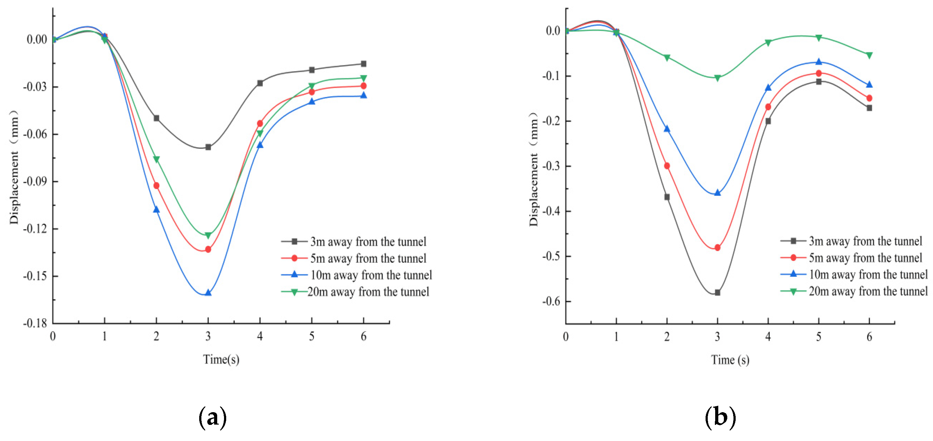
An amount of 4 reference points on the ground surface, 3 m, 5 m, 10 m, and 20 m from the lining on the right side of the tunnel, were selected for the calculation, and the time variation curves of the horizontal and vertical displacements of the 4 reference points were analysed during one train run.
Figure 16a,b shows the curves of horizontal displacement and vertical displacement of the ground surface in time, respectively. Figure 16a shows that the deformation trend in the horizontal direction is more or less the same at the four reference points. The settlement occurs mainly during the 1 s to 3 s when the metro is in motion, and the rebound occurs at 3.2 s to 4.5 s, after which the deformation stabilizes. The area where the deformation occurs is within 5–10 m from the tunnel, with the horizontal displacement of each reference point gradually decreasing over time and eventually stabilising. As can be seen from Figure 16b, the settlement occurs within 1 s to 3 s of train travel and within 5 s to 6 s of travel, and the deformation gradually decreases as the distance from the tunnel axis increases. The area where the larger settlement occurs is located 3 m above the surface of the soil, directly above the lining on the right side of the tunnel, reaching 0.6 mm. The horizontal displacement is the same as the vertical displacement. Part of the residual deformation gradually recovers over time, while the other part becomes permanent due to the non-linearity of the soil material.
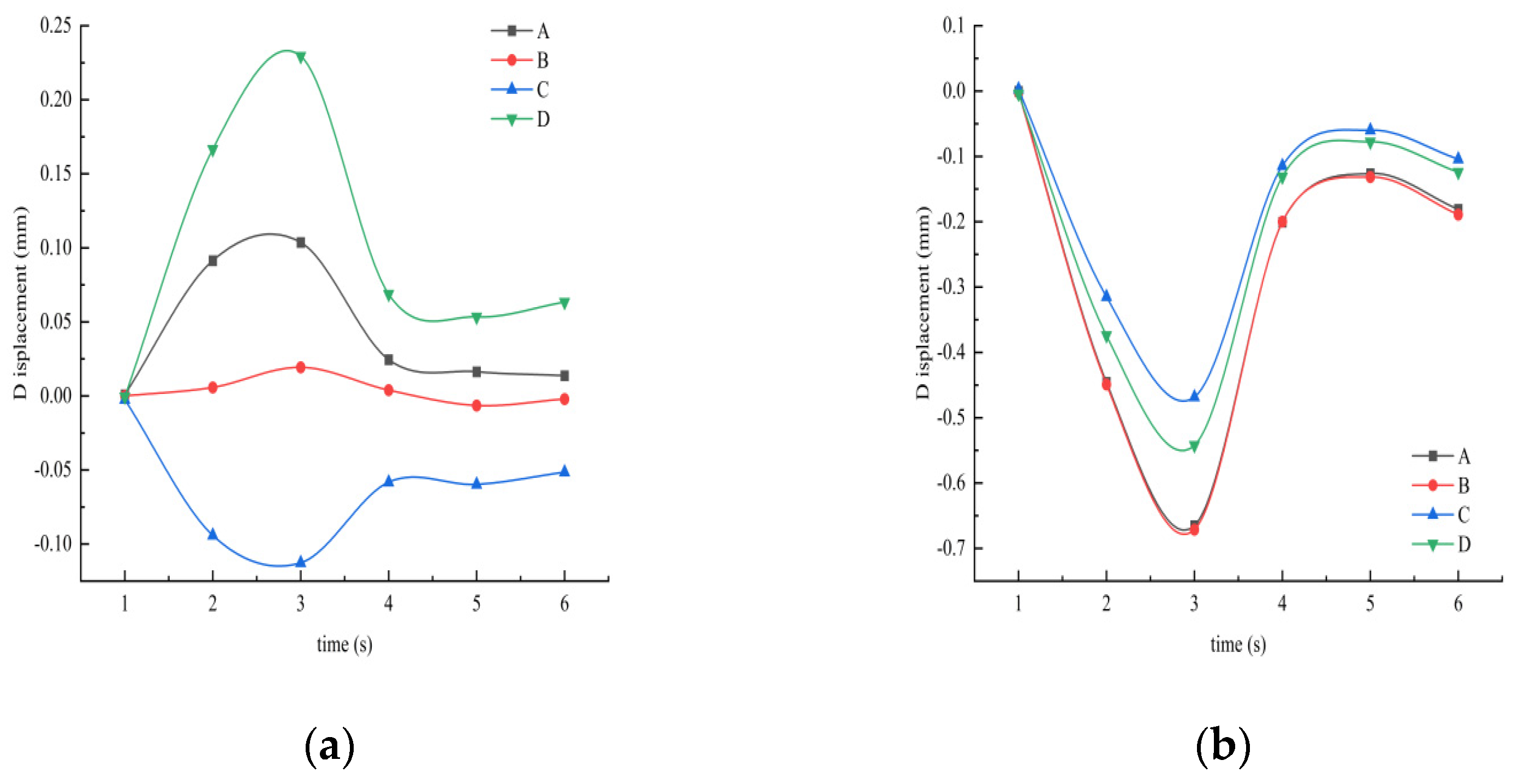
Four reference points A, B, C, and D are selected for the calculation. Point A is 5 m from the left lining of the tunnel and 5 m from the lining above the tunnel; point B is 5 m from the right lining of the tunnel and 5 m from the lining above the tunnel; point C is 5 m from the left lining of the tunnel and 5 m from the lining below the tunnel; point D is 5 m from the right lining of the tunnel and 5 m from the lining below the tunnel. The time variation curves of the horizontal and vertical displacements of the four reference points are analysed during one train run, as shown in Figure 17.
Figure 17a,b shows the horizontal displacement and vertical displacement time course change curves around the tunnel, respectively. Figure 17a shows that the horizontal displacement time course change at monitoring points A, C, and D during the initial 3 s of the train passing by is large, points C and D have slightly larger deformation due to the influence of the train load below the tunnel, points A and B are above the tunnel and have smaller horizontal displacement under the vibration load. Considering the influence of boundary conditions in the finite element model, reflecting the fact that in actual engineering, the soil between the tunnels changes is very complicated due to the influence of the metro train vibration. Figure 17b shows that the settlement mainly occurs within 1~3 s of train movement, with rebound occurring in 3~5 s, followed by stabilisation of the deformation, with the larger area of deformation occurring in the upper powder layer of the tunnel, with a settlement value of 0.7 mm.
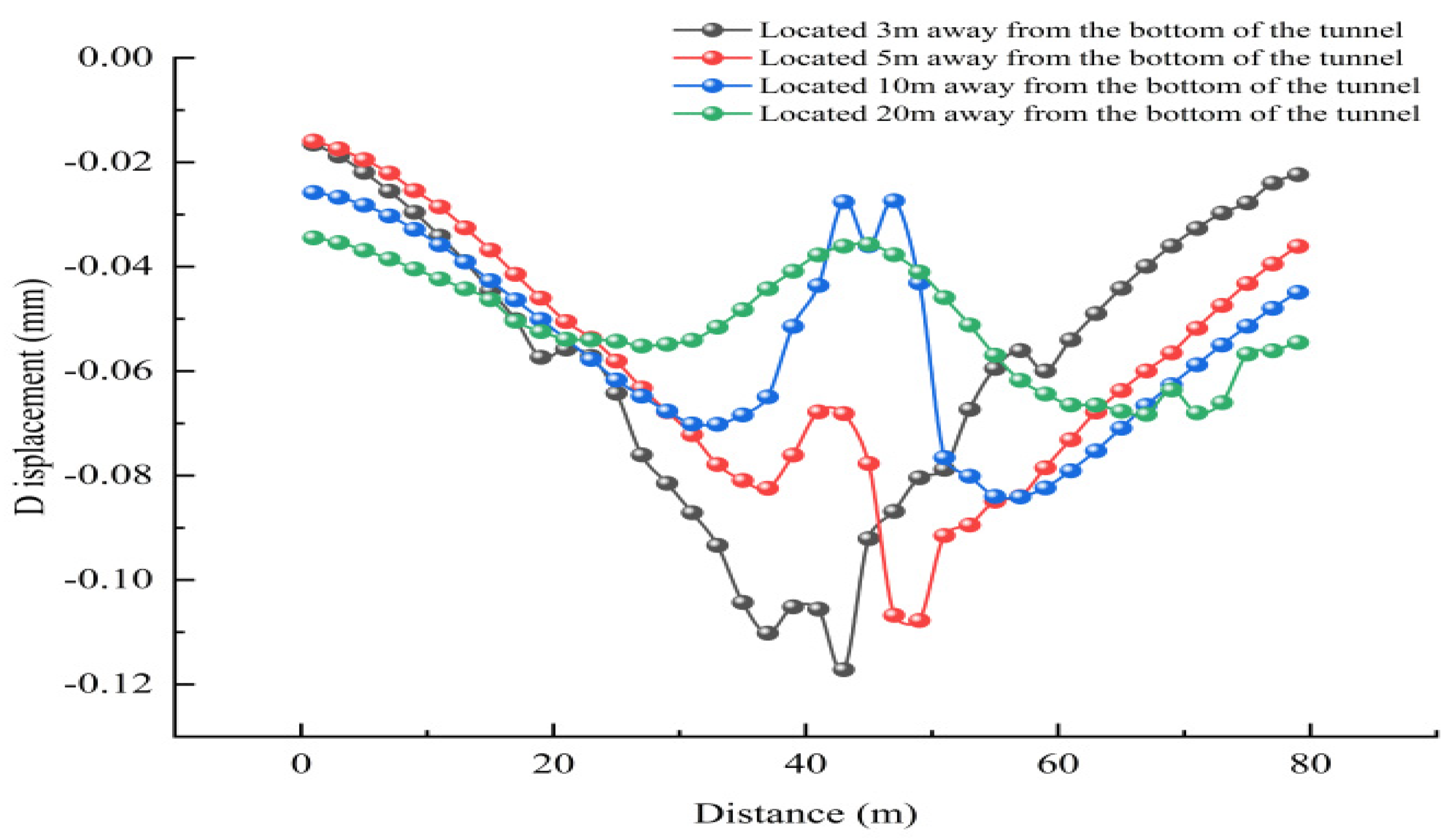
The calculations were carried out at 3 m, 5 m, 10 m, and 20 m from the bottom of the tunnel in the vertical direction. The vertical displacement of the soil after one train run is shown in Figure 16.
As can be seen from Figure 18, at the bottom of the tunnel, the tendency of the soil displacement is “V” shaped. The displacement settlement is large in the middle and small at the ends. As the depth of the soil increases from the bottom of the tunnel, the displacement of the soil in the vertical direction decreases, and the deformation is basically stable at about 20 m from the bottom of the tunnel. Under the vibration load of the train, the displacement response of the local strata directly below the tunnel is the largest, given that the soil is a typical non-linear material and the propagation law of vibration waves in the soil.

3.3. Analysis of Straight Versus Curved Sections

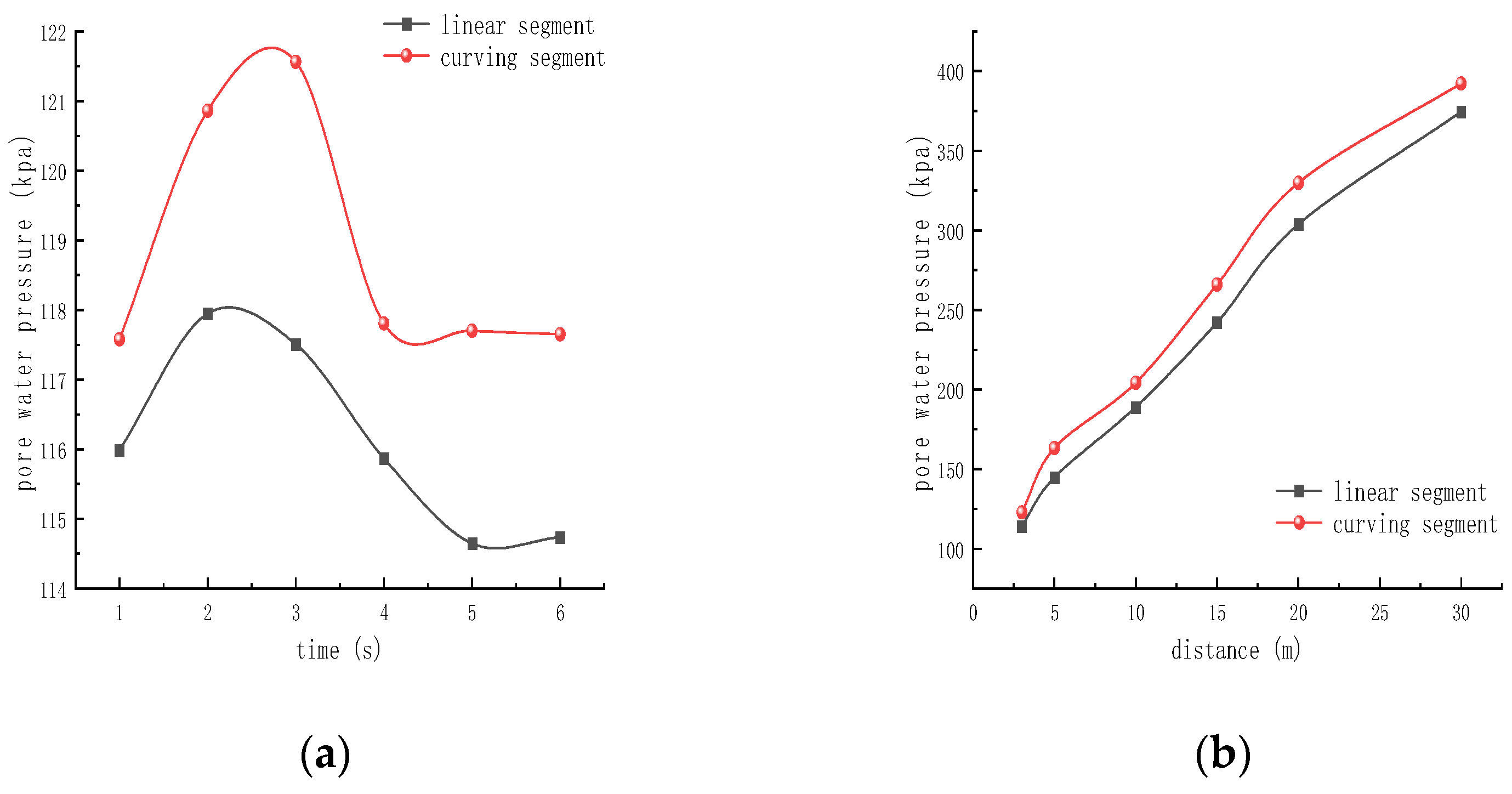
Compared to straight section metro shield tunnels, small curve tunnels are further analysed for pore water pressure and displacement under both straight and curve section conditions due to the presence of ultra-high, centrifugal horizontal loads, resulting in a more sensitive silty soil around the tunnel to cyclic train loads. The pore water pressure time curve at the measurement point directly below the tunnel is shown in Figure 19a. During train operation, the pore water pressure is rapidly generated when the train passes through the tunnel, but due to the transferability of the train vibration load, the pore pressure cannot be discharged quickly, thus, making the pore water pressure drop slowly with time after the train passes. The pore pressure rises 3.283 kpa when the train passes through the curved tunnel, and about 1.961 kpa when the train passes through the straight tunnel The pore pressure in the soil under the curve section of the tunnel is much higher than that in the straight section. This is due to the presence of ultra-high and centrifugal horizontal loads in the curved section, which makes the silt soil more sensitive to train vibration. Figure 19b shows the curve of the peak pore pressure along the depth at the measurement point directly below the tunnel. It can be seen that the pore pressure gradually becomes greater as the depth of the soil layer increases, which is the same pattern as the variation of pore pressure with depth in the previous Section 2.2.2.
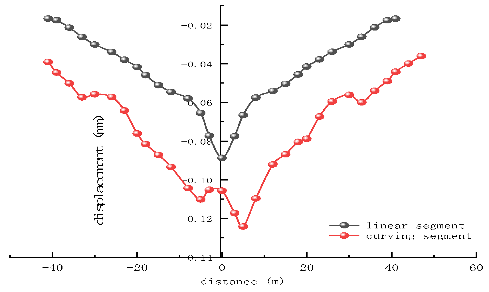
Figure 20 shows the displacement curve of the soil under the tunnel. It can be seen that the settlement of the curved section is greater than the settlement of the straight section, and the soil settles twice during the passage of the train through the curved tunnel, and after the train passes through the tunnel, the soil slowly springs back; the settlement difference at the same point in both cases is 0.023 mm at the beginning, and the distance along the centre line of the tunnel gradually increases. It can be obtained that during operation, the vibrating train load has a small but manageable effect on the soil around both the straight and curved sections.

4. Conclusions and Discussion

In this paper, by conducting field tests on the dissipation of pore water pressure growth in the underlying soil layer caused by metro vibration in a small radius curve section, studying the response characteristics of pore pressure to vibration loads, and establishing a coupled metro ballast-lining-soil dynamic model to predict the development of soil deformation around the tunnel in this section, the paper obtains the following main conclusions:
  • The pore water pressure and excess pore water pressure generated by the initial vibration of the train are not easily dissipated and transferred, resulting in a larger pore pressure in the silty sand layer at the beginning of the train operation. During this, the pore pressure fluctuates due to peak commuting periods and climatic problems, while the fine particles of the powdered sand soil have a small amount of cohesive particles, making the soil layer have a certain strength and cohesion. The pore pressure and excess pore water pressure gradually decrease and stabilise at a later stage under the action of the train vibration.
  • Under the action of cyclic train load, the response of the powder sand soil around the tunnel to train vibration is closely related to the location. The closer to the tunnel, the more sensitive the response is. The upper part of the tunnel arch waist beyond a certain burial depth range with the disappearance of the vibration force pore pressure also decreases rapidly. The soil layer in the lower part of the tunnel arch waist with the disappearance of the vibration effect pore pressure in the short term is not easy to dissipate.
  • Soil liquefaction is related to the type of soil and is less likely to occur in silty soils compared to other soil layers in this tunnel shield section.
  • Under the action of cyclic loading, the greater the horizontal distance from the tunnel, the more slowly the super-pore water pressure decays, and along the vertical direction decays faster, indicating that the soil beneath the tunnel vibrates mainly in the vertical direction. The area where the soil settles more is mainly concentrated on the surface of the soil 3 m from the lining on the right side of the tunnel, in the silt layer on the upper side of the tunnel and 3 m at the bottom of the tunnel, mainly in a “V” shape; i.e., the displacement settlement is large in the middle and small at the ends.
  • The tunnel settlement is reduced from 2 mm to 1 mm during train operation and the resulting track unevenness is more moderate. The deteriorating effect on wheel-rail dynamics is weaker, so the displacement caused by vibration is safe for vehicle operation.

Author Contributions

Conceptualization, X.W. and X.L.; methodology, X.L.; software, X.L. and Y.L.; validation, X.W. and X.L.; writing—original draft preparation, X.L.; writing—review and editing, X.W., Y.L., X.L. and F.T.; visualization, F.T. All authors have read and agreed to the published version of the manuscript.

Funding

This research received no external funding.

Institutional Review Board Statement

Not applicable.

Data Availability Statement

The data presented in this study are available on request from the corresponding author.

Conflicts of Interest

The authors declare no conflict of interest.

References

  1. Ahmed, B.; Habib, T.; Hani, T. Analysis of soil settlement behind bridge abutments. Transp. Geotech. 2022, 36, 100812. [Google Scholar]
  2. Hyungjoon, S.; Yang, Z.; Cheng, C. Displacement Mapping of Point Clouds for Retaining Structure Considering Shape of Sheet Pile and Soil Fall Effects during Excavation. J. Geotech. Geoenviron. Eng. 2022, 148, 04022016. [Google Scholar]
  3. Shen, S.-L.; Wu, H.-N.; Cui, Y.-J.; Yin, Z.-Y. Long-term settlement behaviour of metro tunnels in the soft deposits of Shanghai. Tunn. Undergr. Space Technol. Inc. Trenchless Technol. Res. 2014, 40, 309–323. [Google Scholar] [CrossRef]
  4. Xu, Y.; Xu, J.-L.; Dai, J.; Xu, C.-S.; Cui, C.-Y.; Meng, K. Study of Pore Water Pressure and Deformation Characteristics of Soil below Tunnel under Vibration Load of Metro Trains. Tunn. Constr. 2018, 38, 1785–1792. [Google Scholar]
  5. Lou, P.; Li, Y.; Xiao, H.; Zhang, Z.; Lu, S. Influence of Small Radius Curve Shield Tunneling on Settlement of Ground Surface and Mechanical Properties of Surrounding Rock and Segment. Appl. Sci. 2022, 12, 9119. [Google Scholar] [CrossRef]
  6. Wang, Y.; Chen, S.; Ouyang, J.; Li, J.; Zhao, Y.; Lin, H.; Guo, P. Predicting Ground Surface Settlements Induced by Deep Excavation under Embankment Surcharge Load in Flood Detention Zone. Water 2022, 14, 3868. [Google Scholar] [CrossRef]
  7. Ma, C.-Y. The Dynamic Response Analysis of Liquefaction and Model Test about Underground Structure of Subway in Sand Stratum. Master’s Thesis, Xi’an University of Technology, Shaanxi, China, 2018. [Google Scholar]
  8. Cavallaro, A.; Capilleri, P.P.; Grasso, S. Site Characterization by Dynamic In Situ and Laboratory Tests for Liquefaction Potential Evaluation during Emilia Romagna Earthquake. Geosciences 2018, 8, 242. [Google Scholar] [CrossRef] [Green Version]
  9. Wang, Y.-G. Study on Dynamic Response and Long-Term Settlement of Curved Tunnel under Vibration on Load of Train in Silty Strata. Master’s Thesis, Henan University of Technology, Zhengzhou, China, 2020. [Google Scholar] [CrossRef]
  10. Khosravifar, A.; Dickenson, S.; Moug, D. Cyclic porewater pressure generation in intact silty soils. Soil Dyn. Earthq. Eng. 2022, 162, 107482. [Google Scholar] [CrossRef]
  11. Beiranvand, B.; Rajaee, T. Application of artificial intelligence-based single and hybrid models in predicting seepage and pore water pressure of dams: A state-of-the-art review. Adv. Eng. Softw. 2022, 173, 103268. [Google Scholar] [CrossRef]
  12. Singh, A.; Singh, D.; Chakraborty, M. Effect of various initial excess pore water pressure distributions on 1-D consolidation of clays. Int. J. Geotech. Eng. 2022, 16, 123–132. [Google Scholar] [CrossRef]
  13. Lachinani, H.; Jahanandish, M.; Ghahramani, A. Excess Pore Water Pressure Generation, Distribution and Dissipation in Self-boring Pressuremeter Test: Numerical Analysis. Int. J. Civ. Eng. 2022, 20, 1101–1114. [Google Scholar] [CrossRef]
  14. Luo, Q.; Liu, Y.; Zhou, Y.; Wu, J.; Yie, X. Research on Pore Water Pressure of Saturated Muck Soil Under Traffic Loading of Low Frequency. Am. J. Civ. Eng. 2016, 4, 149–158. [Google Scholar]
  15. Cary, C.E.; Zapata, C.E. Pore Water Pressure Response of Soil Subjected to Dynamic Loading under Saturated and Unsaturated Conditions. Int. J. Geomech. 2016, 16, D4016004. [Google Scholar] [CrossRef] [Green Version]
  16. Castelli, F.; Cavallaro, A.; Grasso, S.; Lentini, V. Undrained Cyclic Laboratory Behavior of Sandy Soils. Geosciences 2019, 9, 512. [Google Scholar] [CrossRef] [Green Version]
  17. Porcino, D.D. Recent advances in pore water pressure and liquefaction characteristics of low plasticity silty sands subjected to cyclic loading. IOP Conf. Ser. Earth Environ. Sci. 2019, 351, 012013. [Google Scholar] [CrossRef]
  18. Karakan, E.; Sezer, A.; Tanrinian, N. Evaluation of effect of limited pore water pressure development on cyclic behavior of a nonplastic silt. Soils Found. 2019, 59, 1302–1312. [Google Scholar] [CrossRef]
  19. Luo, J.; Miao, L. Research on dynamic creep strain and settlement prediction under the subway vibration loading. SpringerPlus 2016, 5, 1252. [Google Scholar] [CrossRef] [Green Version]
  20. Hou, C.Y.; Cui, Z.D. Quantitative Analysis of the Microstructures of Deep Silty Clay Subjected to Two Freezing–Thawing Cycles under Subway Vibration Loading. J. Cold Reg. Eng. 2021, 35, 04021012. [Google Scholar] [CrossRef]
  21. Gao, M.; Xu, X.; Chen, Q.S.; Wang, Y. Reduction of metro vibrations by honeycomb columns under the ballast: Field experiments. Soil Dyn. Earthq. Eng. 2020, 129, 105913. [Google Scholar] [CrossRef]
  22. Tang, Y.-Q.; Cui, Z.-D.; Zhang, X.; Zhao, S.-K. Dynamic response and pore pressure model of the saturated soft clay around the tunnel under vibration loading of Shanghai subway. Eng. Geol. 2008, 98, 126–132. [Google Scholar] [CrossRef]
  23. Ge, S.; Yao, X. Response characteristics of pore pressure in soils nearby metro tunnel due to train vibration loading. J. Eng. Geol. 2015, 23, 1093–1099. [Google Scholar]
  24. Wang, T.; Shi, B.; Ma, L.; Zhang, C.; Deng, Y. Dynamic response and long-term cumulative deformation of silty sand stratum induced by metro train vibration loads. J. Eng. Geol. 2020, 28, 1411–1418. [Google Scholar]
  25. Xiao, Z.-R.; Wang, Y.-G.; Zhang, W.-C.; Ren, L. Effect of train load in silt formation on the settlement of curved tunnel. J. Liaoning Tech. Univ. Nat. Sci. 2021, 40, 327–332. [Google Scholar]
  26. Wei, H. Study on Surface Subsidence and Environmental Impact Caused by Small Radius Curved Tunnel under Buildings. Master’s Thesis, Changzhou University, Changzhou, China, 2021. [Google Scholar] [CrossRef]
  27. Meng, Z.B.; Cui, S.C.; Zhao, T.F.; Jin, L.Q. The Finite Element Model Determination in the Loess Regions under Subway Vibration Loads. Adv. Mater. Res. 2011, 368–373, 2586–2590. [Google Scholar] [CrossRef]
  28. He, P.-P.; Cui, Z.-D. Dynamic response of a thawing soil around the tunnel under the vibration load of subway. Environ. Earth Sci. 2015, 73, 2473–2482. [Google Scholar] [CrossRef]
  29. Meng, Z.B.; Zhao, T.F.; Cui, S.C.; Jin, J. Dynamic Response Analysis under the Metro-Vibration Loading of Xi’an Bell Tower Timber Structure. Appl. Mech. Mater. 2012, 170–173, 1361–1366. [Google Scholar] [CrossRef]
  30. Shan, W.; Chen, H.-E.; Yuan, X.; Ma, W.; Li, H. Mechanism of pore water seepage in soil reinforced by step vacuum preloading. Bull. Eng. Geol. Environ. 2021, 80, 2777–2787. [Google Scholar] [CrossRef]
  31. Yang, Y.; Cai, R.; Zhang, G.; Su, S.; Liu, W. Evaluating and analyzing the stability of loess slope using intermittent rainfall and various rainfall patterns. Arab. J. Geosci. 2022, 15, 218. [Google Scholar] [CrossRef]
  32. Zhang, Z.-L.; Cui, Z.-D. Analysis of microscopic pore structures of the silty clay before and after freezing–thawing under the subway vibration loading. Environ. Earth Sci. 2017, 76, 528. [Google Scholar] [CrossRef]
  33. Duan, Z.; Li, Z.Y.; Wu, Y.B.; Niu, B.; Shen, R.J. Mechanical and microscopic properties of soil according to the rate of increase in pore water pressure. Soil Tillage Res. 2023, 225, 105530. [Google Scholar] [CrossRef]
  34. Wang, M.F. Dynamic Response of Saturated Silt Soil and Liquefaction by the Subway’s Vibration. Master’s Thesis, Beijing Jiaotong University, Beijing, China, 2009. [Google Scholar]
  35. Yuan, Y.; Liu, W.; Liu, W. Propagation law of ground vibration in the curve section of metro based on in-situ measurement. China Railw. Sci. 2012, 33, 133–138. [Google Scholar]
  36. Wang, L.H.; Lu, G.Y. Vehicle Type Selection for Zhengzhou Metro Line 1. Urban Rapid Rail Transit 2013, 26, 119–123. [Google Scholar]
  37. Wang, C.Y.; Zhao, J.Z.; Xu, X.; Kan, Q.H. Three-dimensional Finite Element Analysis of Wheel-rail Contact for Curved subway. J. Sichuan Univ. Sci. Eng. Nat. Sci. Ed. 2018, 31, 36–42. [Google Scholar]
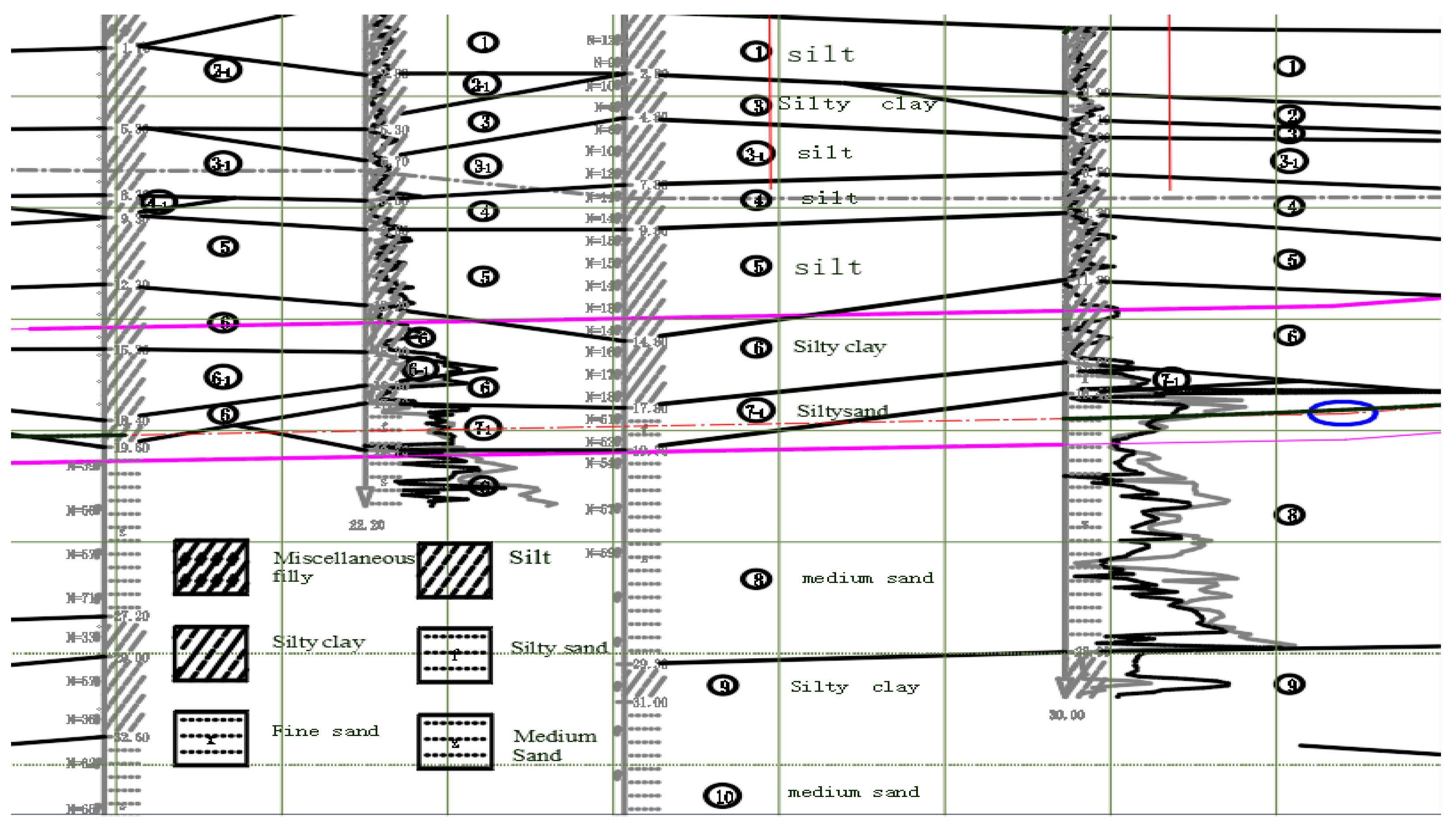
Figure 1. Geological profile of each soil layer.
Water 15 00981 g001
Figure 2. Plan of monitoring site.
Water 15 00981 g002
Figure 3. Pore water pressure variation graph ((a)Automated monitoring points; (b) manual monitoring sites).
Water 15 00981 g003
Figure 4. Change curve of lower pore pressure in different time periods.
Water 15 00981 g004
Figure 5. Variation of pore pressure at different burial depths.
Water 15 00981 g005
Figure 6. Cumulative excess pore water pressure variation diagram.
Water 15 00981 g006
Figure 7. Top view of measurement point placement.
Water 15 00981 g007
Figure 8. Variation in tunnel settlement by period.
Water 15 00981 g008
Figure 9. Curve of A-value over time (4 months).
Water 15 00981 g009
Figure 10. Curve of A-value with depth.
Water 15 00981 g010
Figure 11. Calculation model diagram.
Water 15 00981 g011
Figure 12. Train vibration load profile (v = 80 km/h).
Water 15 00981 g012
Figure 13. Comparison of measured and simulated results ((a)measured; (b) simulation).
Water 15 00981 g013
Figure 14. Excess pore pressure unit location map.
Water 15 00981 g014
Figure 15. Excess pore water pressure variation curve (a) horizontal direction 0.5 m below the tunnel (b) vertical direction 0 m from the tunnel; (c) vertical direction 5 m away from the tunnel (d) vertical direction 15 m away from the tunnel.
Water 15 00981 g015
Figure 16. Time course of surface displacement curve ((a) Horizontal displacement; (b) vertical displacement).
Water 15 00981 g016
Figure 17. Time-course curve of displacement around the tunnel ((a) Horizontal displacement around the tunnel; (b) vertical displacement around the tunnel).
Water 15 00981 g017
Figure 18. Variation curve of displacement at the bottom of the tunnel.
Water 15 00981 g018
Figure 19. Pore pressure variation curve under different working conditions ((a) Pore pressure variation curve at one point; (b) trend of peak pore pressure along depth).
Water 15 00981 g019
Figure 20. Variation curve of displacement under different working conditions.
Water 15 00981 g020
Table 1. Table of physical and mechanical properties of each soil layer.
StrataGSMoisture Content (w)Porosity (e)Clay Content (%)
silt2.717.80.70315.9
silt clay2.7224.60.79914.7
silty sand2.6323.20.6814.7
fine medium sand2.6318.10.52512.3
Table 2. Depth of monitoring points from the tunnel and monitoring methods.
Monitoring PointsClearance of the Monitoring Point from the Outer
Profile of the Interval Tunnel/m
Distance
Between the Bottom of the Hole and the Tunnel Floor/m
Monitoring Points
Borehole Depth/m
Monitoring Methods
K14.80.521.5Automatic
K23.60.921.5manual
K3-14.60.620manual
K3-24.63.623Automatic
K3-34.68.628Automatic
K3-44.618.638Automatic
K44.80.819manual
K53.30.818Automatic
K63.70.521.5manual
K73.90.921.5manual
K84.40.520manual
K93.80.619manual
K103.60.618manual
K11-140.520manual
K11-243.523manual
K11-348.528manual
K11-4418.538manual
Table 3. Three-dimensional finite element model parameter table.
StrataE (Mpa)μγ (KN/M3)Φ (°)C (KN/M3)K
Miscellaneous fill/0.371718105.8 × 10−6
Silt13.60.318.423155.8 × 10−6
Silty clay8.10.31915205.8 × 10−7
Silty sand170.31831.321.2 × 10−4
Silt120.2520.625185.8 × 10−6
Fine Medium Sand30.50.251835.902.4 × 10−4
Silty clay10.50.320.218285.8 × 10−7
Lining36,0000.22500///
μ = Poisson’s ratio.
Disclaimer/Publisher’s Note: The statements, opinions and data contained in all publications are solely those of the individual author(s) and contributor(s) and not of MDPI and/or the editor(s). MDPI and/or the editor(s) disclaim responsibility for any injury to people or property resulting from any ideas, methods, instructions or products referred to in the content.