Abstract
Real-time simulation of hydraulic fracturing operations is of critical importance to the field-scale stimulation applications. In this paper, we present an efficient yet reasonably accurate program for the numerical modeling of dynamic fractures. Our program, named as FracCSM, is based on combined Integrated Finite Difference (IFD) method and Discontinuous Displacement Method (DDM). FracCSM simulates the initiation and propagation of hydraulic fractures with DDM and mass/heat transport inside fractures by IFD. The frictional loss within the wellbore is also taken into consideration. In this way, we are able to model the propped height and length of the fractures subject to the stress interference effect. Moreover, FracCSM captures the stress shadow effect of multi-stage fractures. To facilitate the monitoring and decision making during the hydraulic fracturing process, we have developed a general framework that supports real-time simulation of fracture propagation. Our developed program demonstrates sound accuracy in comparison with existing simulators. The novelty of this work is the combined simulation algorithm to simulate the multiphysical process during hydraulic fracturing operations. We will demonstrate the program structure as well as the field applications of FracCSM to the real-time simulation of hydraulic fracturing operations in Sulige tight sandstone reservoir.
1. Introduction
The hydraulic fracturing technique has been widely used in the development of unconventional reservoirs. During the fracturing process, fracture fluids are injected underground to crack the reservoir rocks. Such operations are usually fulfilled within hours to days. Considering the fast pace of the field operations, the real-time modeling of the hydraulic fracture operations is therefore of critical importance, as it visualizes the dynamic growth of downhole fractures and allows field engineers to adapt the operation parameters accordingly. The real-time simulation is challenging in two aspects. First, it requires the simulator to produce the numerical results fast enough. Secondly, it needs the simulator to interact with the hydraulic fracturing facilities, in order to pick up and interpret the real-time signals. Therefore, tremendous efforts are demanded in the development of such a program. In this paper, we will show the progress we have made in the above-mentioned regard.
The earliest trials of simulating the propagation of hydraulic fractures date back to the 1960s, when the PKN [1,2] model and the KGD [3] model were developed. PKN and KGD models presume the shape of the fractures, which may not reflect the real conditions well. To conduct realistic simulation of fractures, more comprehensive numerical methods have been proposed. Among them, Finite Element Method (FEM) and its variants are the most widely used [4,5,6,7]. Classic FEM relies on re-meshing to track the propagating fracture, which increases the. computational load. To resolve such an issue, the Extended Finite Element Method (XFEM) [8,9,10] has been developed. XFEM adopts ‘enriched’ basis functions to allow crack growth within an FEM element. Therefore, XFEM permits flexibility in handling 2D and 3D fracture growth. One potential drawback of XFEM lies in its huge computational cost, which prevents its wide application to the real-time simulation of field-scale problems.
The Discrete Element Method (DEM) [11,12,13] is flexible in handing the discontinuities of fractures. DEM can also be coupled with damage mechanics and flow simulation [14,15,16]. However, in most cases DEM is based on rigid body elements, which are known to have the ‘scaling’ issue [17]. A hybrid finite-discrete element method [18,19,20] has also been proposed, which adopts the discrete element method to simulate the fracture and adopts the finite element method to simulate the surrounding area in the vicinity of the fracture.
Wu and Olson [21,22] have adopted Discontinuous Discontinuity Method (DDM) for the simulation of multistage fractures. Based on Green’s theorem, DDM effectively reduces the simulation of the stress field to the boundary element, which makes it very convenient in tracking the propagation of complex fracture networks [23]. Recently, DDM has been extended to inter-well interference [24]. One potential drawback of DDM is that it is difficult to apply in heterogeneous problems. Besides discrete fracture (fracture planes) simulation, the propagation of complex fracture networks has also been investigated. Kresse et al. [25], Weng [26] and Weng et al. [27] developed the Unconventional Fracture Model (UFM) to simulate the fracture growth in naturally fractured reservoirs in the ‘wiremesh’ manner. In such approaches, the fractures are not modeled distinctly but as a network, to account for the complex fracture-fracture interaction. The propagation of fractures is based on energy criteria. Recently, Li et al. [28] investigated the hydrate-bearing wellbore stability with potential fracturing risks. Moreover, Li et al. [29] studied the potential application of CO2 as a fracturing fluid.
Although huge success has been achieved in the development of numerical models, a comprehensive simulator that accurately simulates the fracture propagation and proppant distribution while it maintains fast computational speed is still a challenge. In this work, we have developed a practical simulator, named FracCSM, based on combining the Integrated Finite Difference (IFD) and DDM methods. FracCSM is compositional, tracking the mitigation of every fluid and proppant component. The mass loss induced by fluid leakoff and energy loss caused by friction and thermal conduction have also been taken into consideration. We have integrated DDM with IFD. In our simulator, the DDM method is used to predict the fracture propagation, while IFD is used to simulate the fluid transport inside the fracture plane. The real practice of hydraulic fracturing operations demands the real-time monitoring of fracture growth underground. To fulfill such a goal, we have developed a novel framework for the real-time simulation of hydraulic fractures. In this framework, the program picks up and interprets the signal from the hydraulic fracturing facilities and sends it to the simulation engine for dynamic prediction, using the multi-process technique. Our approach has been used to conduct field-scale real-time hydraulic fracturing in the tight sandstone formations in Sulige gas field. This paper is arguably the first to document such advancement. Compared to previous works, the novelties of our work lie in the following aspects: the integration of DDM and IFD, the wellbore treatment and the real-time simulation framework.
This paper is organized as follows. In Section 2, we present the mathematical model of FracCSM, including the transport model and the fracture mechanics model. In Section 3, we describe the numerical approaches used in FracCSM, including the discretization scheme, combined framework and real-time simulation module. In Section 4 and Section 5, we present the validation and discuss the numerical results of FracCSM, respectively. In the last chapter, we conclude and summarize the work.
2. Mathematical Model
2.1. Fracture Initiation and Propagation
In this section, we present our fracture mechanics model, including the fracture extension criteria as well as the determination of the fracture width.
In FracCSM, the fracture is simulated on a dynamically growing rectangular grid. The fracture is allowed to propagate along the horizontal (x-direction) and vertical direction (z-direction). To account for the stress interference among fractures, we allow the fracture plane to deviate along the y-direction. The grid block size can be non-uniform, which will be explained in detail in Section 3.1.
To describe the failure mechanism used in FracCSM, we start with the calculation of the stress intensity factor for Mode-1 failure, as follows [30]
where denotes the normal displacement of the grid block at the fracture front, which is obtained by DDM as shown in Section 3.2. is the half length of the current fracture plane. and are the Young’s modulus and Poisson’s ratio, respectively. This correlation is also used in the work of Olson [31] and Sheibani [32]. We follow Mastrojannis’s approach [33] to model the front propagation. We introduce the concept of front propagation velocity, which is the function of rock toughness , as follows.
in which Cext and n are rock internal properties.
At each time step, we make a comparison between the stress intensity factor and the rock toughness. If the former is larger than the latter, the fracture front is allowed to propagate along the horizontal (x-) direction and the vertical (z-) direction. The formulation of the propagation distance is shown below
where is the height of the fracture at position x, as shown in Figure 1. and are the grid block size along x- and z- direction, respectively. The grid system as well as the definition of x and z-direction will be explained in detail in Section 3.1. is the position of the grid block along z- direction. is the time step length.
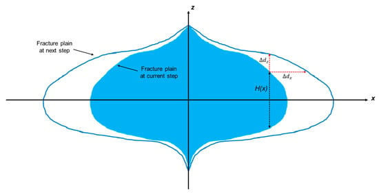
Figure 1.
Conceptual model of a propagating fracture plane. The fracture is allowed to propagate along x-direction and z-direction and to deviate along y-direction which is perpendicular to the fracture plane.
We use net pressure to update the fracture width. is calculated as
where is the pressure inside the fracture. The solution is described in Section 2.2. is the minimum principal stress acting on the fracture plane, the calculation of which is fulfilled by the combination with DDM and is described in Section 3.2.
The initiation of the fracture is subject to the breakdown pressure and the rock properties as well as the in-situ stress condition. The breakdown pressure Pb is calculated as follows [30].
where is the tensile failure stress. is the pore pressure of the formation. is the pore pressure factor (treated as porosity in this work) [34]. is Biot’s coefficient. is the maximum principal stress.
2.2. Mass Transport Inside the Fracture
FracCSM has a comprehensive model to simulate the transport of mass and energy by tracking every mass component in the slurry. In FracCSM, the injected slurry is simulated with a compositional model, where it is modeled as a mixture of proppants and fluid components, including gel and additives. In our model, the velocity of all fluid components is assumed to be the same, set as , while the velocity of proppants can differ from each other, subject to the settling effect and particle-wall interactions. The governing equations of both fluid components and proppant components are derived from the following mass conservation equation, as follows [35].
where , and are the density, velocity and fracture width, respectively. The fracture is set as a thin slit within the local x-z plane, ignoring the tortuosity.
For a system with types of proppant components and types of fluid components, the mass conservation equation within the fracture plane is as follows.
In the above equation, the first and second term represent the convective flow. The third term is the accumulation term and the last term is the leak-off rate. and are the concentration of the ith type of fluid and the ith type of proppant, respectively.
The mass conservation of the ith type of proppant components satisfies the following equation.
To accurately simulate the mass transport of all components, the key lies in the calculation of the fluid component velocity and the proppant component velocity .
We define a slurry velocity , which is the weighted summation of the fluid velocity and the proppant velocity, as follows [35].
The velocity of the slurry is subject to the pressure gradient and the gravity effect, as below.
in which γsl is the gravity acceleration term. represents slurry viscosity. Based on Equation (9), the fluid component velocity calculated as follows.
The above formulation is substituted into Equation (8) with the fluid pressure and the concentration as primary variables.
The proppant velocity consists horizontal component and vertical component .
is calculated by adding the slurry velocity with a settling velocity
is calculated by the Friehauf’s model [36], as follows.
where is Stoke’s velocity; ,which is the function of Reynold’s number , represents the inertial effect, quantifies the particle-particle interaction effect; and , which is the function of particle diameter and fracture width , quantifies the particle-wall interaction effect. Their detailed formulations can be found in [37,38]
For the horizontal direction (x-direction), the proppant velocity is calculated as [35]
In the above equation, the parameter is calculated as
and
where is the particle diameter of the ith type of proppant. Similarly to the treatment for fluid velocity, the proppant velocity is substituted into Equation (8) to solve the mass transport of proppants.
The viscosity of the slurry is calculated by the power-law model [27] as
where is the maximum value of proppant concentration, beyond which the slurry will cease flowing. is the power-law parameter. and are the viscosity and mole fraction of pure fluid component without proppants, respectively. The detailed formulation of the viscosity calculation can be found in [34].
2.3. Leak-Off Rate Calculation
During the fracturing process, fracturing fluids leak into the formation, subject to the permeability of the formation rock, the fluid viscosity, and the pressure difference between the fracture and the formation. In FracCSM, the leak-off rate is calculated with the three-zone model, as introduced by Schechter [39]. In the three-zone leak-off model, the formation surrounding the fracture is assumed to be sandwich-like, consisting of the filter cake zone, the invaded zone and the compressed formation fluids zone. The filter cake zone refers to the filter cake formed by slurry on the fracture face. The invaded zone is the zone in the vicinity of the fracture face that is (partly) invaded by the slurry. The compressed formation fluids zone refers to the formation that is relatively far away from the fracture and is impacted by the stress change induced by injection. A conceptual model of the three zones is shown in Figure 2.
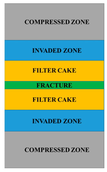
Figure 2.
A sketch of the three-zone leak-off model, following [39].
The fluid flow within the compressed formation fluids zone is modeled as the single-phase flow of a slightly compressible fluid in a semi-infinite medium. The fluid velocity, vN, at the interface between the compressed formation fluids zone and the invaded zone can be calculated as follows [40].
where and refer to the porosity, permeability of the reservoir rock, respectively. and are the compressibility and viscosity of the fluid. τ is the time when leak-off commences. and are the pressure of the invaded zone and the compressed formation fluids zone, respectively. is the overall leak-off coefficient of the compressed formation fluids zone.
For the invaded zone, the fluid velocity obeys Darcy’s law and the zone grows as fluid enters it. The fluid velocity in the invaded zone is given by:
where Pcap is the capillary pressure between the invading fluid and the reservoir fluid. is the pressure of the filter case zone. is the overall leak-off coefficient of the invaded zone.
The fluid velocity between the fracture and the filter cake zone is calculated as
where is the pressure inside the fracture and is the overall leak-off coefficient of the filter cake zone.
is related to a laboratory-measured parameter mw, which is the slope of a plot of filtrate volume with respect to the square root of time.
Since the velocities in Equations (18)–(20) are equal to each other, we can obtain an overall leak-off coefficient as
where
and
In the above equation, is the overall pressure drop.
2.4. Energy Transport Inside the Fracture
The general energy balance for a component that takes into account advection and conduction is
where K is the thermal conductivity, is the specific enthalpy, is the specific internal energy, and is the energy source/sink term. In FracCSM, the conduction term in the above equation is ignored, because of its relatively trivial contribution to the overall energy transport compared to the advection term. By integrating Equation (25) over the fracture width, we get
In the above equation, the specific enthalpy and internal energy can be calculated as
and
For each proppant or fluid component, the specific enthalpy and internal energy are assumed to be equal and can be calculated as
where C is the specific heat capacity. The heat loss per unit area through the fracture faces is calculated as
where Kres, ρres and Cres are the thermal conductivity, density and heat capacity of the reservoir formation, respectively. τ is the starting time of the heat loss, as used in Carslaw and Jaeger [41].
2.5. Mass/Energy Transport Inside the Wellbore
In this section, we present the mass and energy conservation equations of mass and energy transport inside the wellbore.
The wellbore is modeled as a series of connected well segments along the well trajectory. The slurry flow inside the wellbore is modeled as piston-like flow segments. The conceptual model of the well segments and the slurry segments are shown in Figure 3. The properties of slurry, including density and viscosity, are calculated using the same approach as in the fracture.
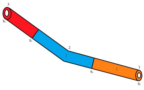
Figure 3.
Schematic of a wellbore with two wellbore segments and three slurry segments. S refers to cross-section area and the numbers refer to the index of fluid segments.
We track the boundary of each slurry segment, which is denoted by Si, inside the wellbore during the simulation. The boundaries of the slurry segment are denoted by Si. The numbering of these slurry segment boundaries starts at one, the wellbore bottom, and increases as the wellbore is traversed toward the wellhead, with the last segment boundary being SN+1 (where N is the number of well segments) that is located at the wellhead. The slurry is injected into the wellbore at the wellhead and leaves the wellbore through perforations.
The mass conservation equation of the fluid and proppant components in slurry segment i is
In the above equation, the subscripts p and f denote the fluid and the proppant components, respectively.
Aann is the annular area, x denotes component volume fraction, Tws is transmissibility per unit length for slurry loss to the surroundings, Pw and Psurr are the wellbore pressure and the surrounding pressure, respectively. qinj is rate of the injected slurry. The transmissibility per unit length for slurry loss to the surroundings is only non-zero along completed intervals.
The pressure along the wellbore is calculated as follows.
In the above equation, g is the gravitational term and S denotes wellbore trajectory. Pw,fric is the frictional pressure, which is obtained as follows.
In the above equation, Dh is the hydraulic diameter. The friction factor f is calculated based on Reynolds number, as follows. For laminar flow, friction factor is 16/NRe and in correlations for turbulent flow the friction factor is given by the following equation [42].
The energy balance equation for a slurry segment is
where qloss is the rate of heat loss per unit area from the slurry to the surroundings and Do is the outer wellbore diameter for fluid flow. Heat loss from the slurry to the surroundings is modeled as heat flow through a uniform medium. In this work we derive the overall heat transfer coefficient for the medium based on the analytical solution of transient heat flow with a point heat source [41].
The temperature profile for transient heat flow through a uniform infinite medium with a point heat source in the center is as follows
Based on the above equation, the heat flow, Q profile is
In the above two equations, r denotes the radial distance to the center, while kth and αth are the thermal conductivity and the thermal diffusivity of the media, respectively. αth is thermal diffusivity, Q0 is the magnitude of the heat source (per unit length), t refers to time, τ is the time at which the heat source is activated, and Ei is the exponential integral function. Using Equations (36) and (37), the heat flow between the wellbore and the surroundings can be calculated.
3. Numerical Approach
In this section, we introduce the numerical approach we use in FracCSM. We first describe the integrated finite difference method for the mass/energy transfer, then introduce the DDM method for the stress calculation.
3.1. Integrated Finite Difference Discretization
In this sub-section, we present the mathematical algorithm of the integrated finite difference (IFD) method [43]. The IFD method discretizes the fracture plane into rectangular elements. In each element, the conservation of mass and energy is calculated, based on the governing equations shown in Section 2. We refine the grid along z direction to account for layers with different thickness. Along y direction, the elements are subject to the stress interference effect that is calculated by the DDM method.
The conceptual model of the fracture is as shown in Figure 4. Once the stress condition at a grid block meets the failure criteria in Equation (3), the grid block is activated (marked in green color in Figure 4). FracCSM calculates the mass/energy conservation on all activated grid blocks. The generation of the grid can be referred to the work of Bonduà et al. [44] and Hu et al. [45].
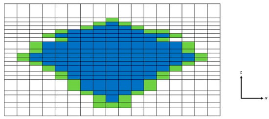
Figure 4.
Conceptual model of fracture on the grid in FracCSM. Green grid blocks refer to newly activated (cracked) grid blocks on the edge of the fracture at the current time step. Blue grid blocks refer to grid blocks that were cracked in previous time steps, while grid blocks refer to intact rocks.
In the IFD method, we integrate the governing equations over each sub-domain and express the resulted flux terms using the divergence theorem. The details of the IFD method can be described as follows. Consider the generalized conservation equation
where k refers to a specific component. M and F are the accumulation term and the flux term, respectively, and q is the source/sink term. By integrating the above equation over a grid block Vn, we get
In the above equation, V refers to volume and refers to surface area.
We can express the integral of the accumulation term over the sub-domain volume as
Meanwhile, for the flux term, we have
where is the normal vector, Anm is the interface area between Vn and Vm. The time derivative term is discretized by the forward difference quotient. There, Equation (39) becomes
where l is the time step index.
All component conservation equations are solved simultaneously by Newton–Raphson method in a fully implicit manner. The primary variables are the liquid phase pressure, temperature and concentration. Therefore, there are equations for each block. The resulting linear system is solved by a multiscale linear solver [46]. The details of the Newton–Raphson method used in FracCSM can be found in Wang et al. [47].
3.2. Combination with DDM
FracCSM combines IFD with Discontinuous Displacement Method (DDM) [48] to capture the stress shadow effect and calculates the derivation of fractures. FracCSM uses DDM to calculate the stress field in the vicinity of fractures. The stress field obtained from DDM is imposed on the grid system in IFD to determine the stress condition surrounding the fracture front as well as each grid block in the fracture plane. The stress field is then used to calculate the deviation and width of the fracture. The displacements of each fracture element are defined in the local coordinates shown in Figure 5 with x3 axis along the normal displacement direction.
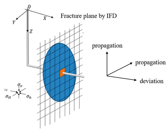
Figure 5.
D view of the fracture plane with IFD method.
The fracture deformation induced normal stress , strike direction shear stress , and dip-direction shear stress , that are applied on fracture element i can be calculated with the following equations.
where N is the total number of elements and A is the matrix of influence coefficients given by [23]. For opened fractures, the total normal stress is equal to the fluid pressure and both strike and dip shear stresses are zero on no-slip fracture surfaces.
The 3D view of the IDF-DDM method with fracture propagation as well as fracture deviation is shown in Figure 5. The details of the implementation of DDM in FracCSM are described in Tang et al. [49].
3.3. Real-Time Monitoring and Simulation
The hydraulic fracturing facility sends out the information of surface pressure (tubing and casing pressure), injection rate, proppant concentration and stage index every second through a certain data port (RS232 in our case). A real-time monitoring and simulation module collects, interprets and visualizes the transient fracturing information. It enables field engineers to monitor the fracturing process and reduces the risks of screen-out.
In our program, the real-time module is realized by multi-process computing. Three processes are involved in the simulation. During the injection period, Process 1 collects signals from the RS232 data port per second and interprets the signal. The extracted information is then sent to Process 2 and Process 3. Process 2 visualizes the surface pressure, injection rate as well as the proppant concentration, enabling field engineers to monitor the ongoing fracturing process. Process 2 also provides the users the real-time user-interactive fracture test functions [40], such as G function analysis, square root pressure analysis and step rate test analysis. Process 3 receives the extracted information from Process 1 every second. Every four seconds, Process 3 conducts one step of simulation by averaging the received pressure and rate data. Process 3 calculates the transient fracture geometry as well as transient proppant distribution. The simulation results are then outputted and visualized by Process 3.
Such a design guarantees that all processes will not interfere with each other. The workflow of the module is as shown in Figure 6.
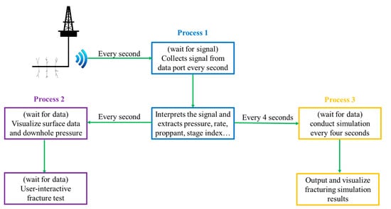
Figure 6.
Workflow of the multi-process real-time simulation module.
4. Validation and Results
In this section, we present the validation of FracCSM. We compare our software with both finite element method and commercial fracture software for the case of single (bi-wing) fractures. The validation for multiple fractures can be found in [49]
4.1. Comparison with Finite Element Method
In this sub-section, we simulate the fracture growth in a homogeneous domain using FracCSM and compare the result with that from a finite element code [50]. In this case, we do not consider the gravity effect and the leak-off effect. Therefore, the fracture will develop into a radial shape. In this case, the Young’s modulus, Poisson’s ratio and Biot coefficient of the rock are 17.24 GPa, 0.25 and 1.0, respectively. We set the gird length along the x and z direction to be 10 m by 10 m. The injected slurry is assumed to have a constant viscosity of 40 cp. The slurry is injected for 30 min with a constant rate of 3.18 m3/min in the center of the domain. The profiles of fracture width at the end of the injection simulated by our program and by the finite element code are compared in Figure 7. It can be seen that the two programs produce close results. Moreover, the radius of the fracture in this case can be analytically calculated. We compare our result with the analytical solution obtained by Geertsma and Klerk [3] in Figure 8. As shown by the figure, our result match the analytical solution well.
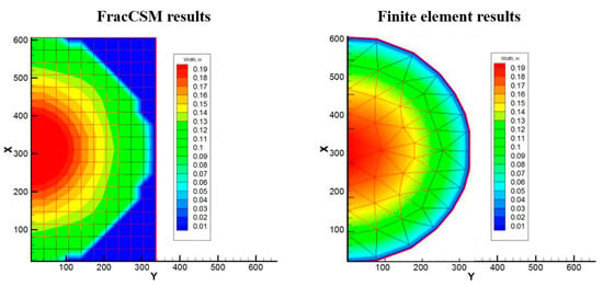
Figure 7.
Simulated fracture width after 30 min injection. The right sub-figure is modified from [50].
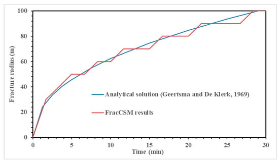
Figure 8.
Comparison between simulation and analytical solution [3] for fracture radius versus time.
4.2. Comparison with Commercial Fracturing Software
In this section, we present the comparison of the results of FracCSM and an industrial standard fracture software Fracpro PT [51]. Fracpro PT is a 3D hydraulic fracturing simulation software that is widely used for the design and analysis of hydraulic fracturing operations. We will use real field data and compare our simulated fracture geometry as well as proppant concentration distribution to validate our program.
In this case, a sandstone layer with the thickness of 30 m is sandwiched by two caprock layers (treated as shale layers). The depth of the upper boundary of the sandstone layer is 3000 m. The properties of the rock and liquid, the in-situ stress distribution as well as the numerical parameters used for the numerical simulation are listed in Table 1. A vertical well is perforated in the middle of the sandstone layer and slurry is injected into the formation through the wellbore based on the pumping schedule listed in Table 2.

Table 1.
Parameters for the comparison with Fracpro PT.

Table 2.
Pumping schedule used for the validation with Fracpro PT software. The stage index refers to the sequence of injected segments.
The fracture planes as well as the proppant distribution within the fracture simulated by the two programs are compared in Figure 9. In Table 3, total length and total height refers to the fracked length and fracked height, respectively, while propped length and propped height refer to the length and height of the fracture that is supported by proppants, respectively. From Table 3 and Figure 9, it can be seen that in general FracCSM matches well with the results of Fracpro PT. The fracked geometry predicted by FracCSM is slightly larger than that of Fracpro PT, while the propped geometry of the two softwares are close to each other. This is partly because that Fracpro PT uses a different approach (unpublished) to calculate the wellbore flow, resulting in lower downhole hydraulic energy, which leads to smaller fracked geometry. It should be noticed that the proppant concentration distribution calculated by the two softwares is different, although the proppant front and fluid efficiency predicted by them are very close. In the results of FracCSM, the proppant concentration in the vicinity of the perforation is significantly higher than the rest of the fracture plane, while in the results of Fracpro PT, the proppants spread more ‘uniformly’ in the fracture plane. This is attributed to the slurry viscosity correlation adopted by FracCSM, that when proppant concentration increases, the viscosity of slurry increases exponentially and the mobility decreases exponentially. This leads to the fact that the proppants that are injected at very late stages will accumulate near the perforation.
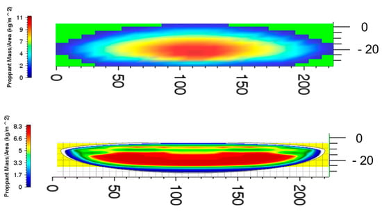
Figure 9.
Comparison of the fracture geometry and proppant concentration distribution predicted by FracCSM and Fracpro PT. Upper: fracture plane simulated by FracCSM. Lower: fracture plane simulated by Fracpro PT.

Table 3.
Comparison of the fracture geometry factor between FracCSM and Fracpro PT.
5. Results and Discussion
In this section, we present the applications of our program and discuss the numerical results.
5.1. Numerical Study of Single Fracture in Multi-Layer Reservoirs
In this sub-section, we apply the developed program to five cases with multiple rock layers to investigate the stress offset impacts on fracture propagation. In these cases, high-permeable sandstone layers with different values of thickness are sandwiched by low-permeable shale layers, as shown in Figure 10. The thickness of the sandstone layer is 12 m for all the five cases.
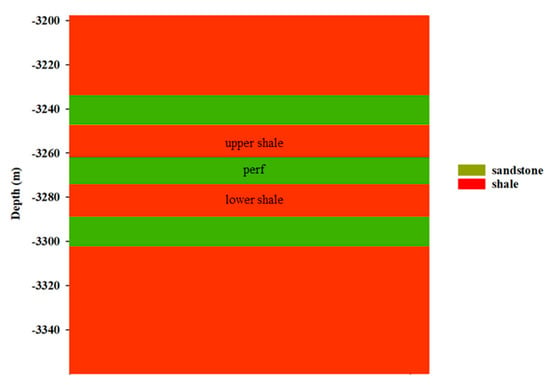
Figure 10.
The profile of the multi-layer formation.
The thickness and stress of shale and sandstone layers of the five cases we run are listed in Table 4. The properties of the rocks and other essential input parameters are listed in Table 5. The pumping schedule of the five cases is listed in Table 6. The leak-off rate profiles across the fracture plane of Case 1 at different times are shown in Figure 11. At the early stage, the leak-off rate is relatively higher, and leak-off occurs across the entire fracture. At the late stage of injection, the leak-off rate becomes very small, and leak off only occurs at the front of the fracture, which indicates that the tight sandstone formation will quickly get saturated because of the low permeability. As predicted by FracCSM, about 30% of fluids leaked into the formation, which is in accordance with field observations.

Table 4.
Formation properties of the five cases. (‘Stress’ refers to the minimum principal stress.) The stage index refers to the sequence of injected segments.

Table 5.
Input parameters for the case study.

Table 6.
Pumping schedules of the five cases. The stage index refers to the sequence of injected segments.
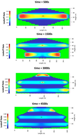
Figure 11.
Variation of leakoff rate distribution of Case 1 during the injection.
The stress profile and simulation results of Case 1 to Case 5 are shown in Figure 12, Figure 13, Figure 14, Figure 15 and Figure 16, respectively. By comparing the results of Case 1 to 3, when the stress contrast between the shale interlayer and the tight sandstone layer is 6 MPa, the thickness of the neighboring shale interlayers should be at least 20 m to prevent the fracture from penetrating. This phenomenon is partly because the fracture toughness values of shale and tight sandstone in this reservoir are close to each other. It should be noted that, although the fracture propagates through the shale layers, the shale layers are not well-propped, because of the higher stress in these layers. The higher stress in the caprock layer will limit the height growth of the fracture, causing the fracture to be longer given the same amount of injected fluids. Meanwhile, the permeability of the formation plays an important role. When the permeability of the formation is higher, there are more fluids leaked off into the reservoirs. The loss of fluids in the fracture leads to higher viscosity of the proppant-bearing fluids, so that the proppant cannot be transported to certain layers. This phenomenon was largely ignored in the existing literature and we have used numerical experiments to examine it.
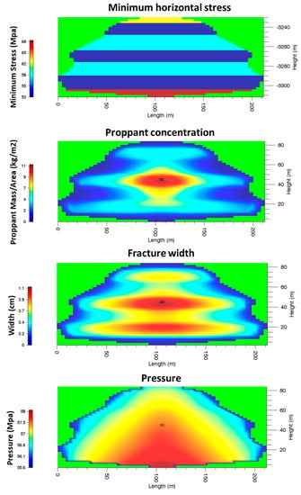
Figure 12.
The stress profile, fracture width, proppant concentration and fluid pressure across the fracture of Case 1.
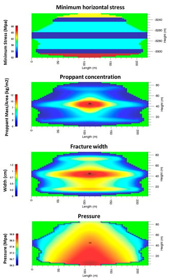
Figure 13.
The stress profile, fracture width, proppant concentration and fluid pressure across the fracture of Case 2.
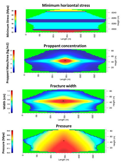
Figure 14.
The stress profile, fracture width, proppant concentration and fluid pressure across the fracture of Case 3.
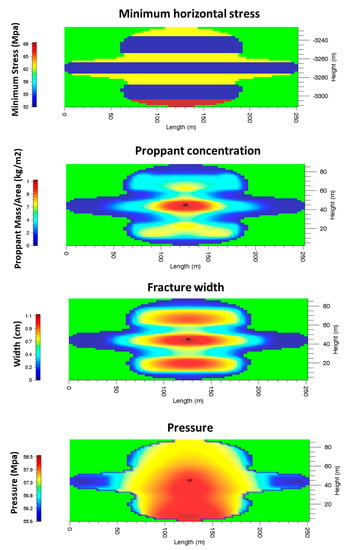
Figure 15.
The stress profile, fracture width, proppant concentration and fluid pressure across the fracture of Case 4.
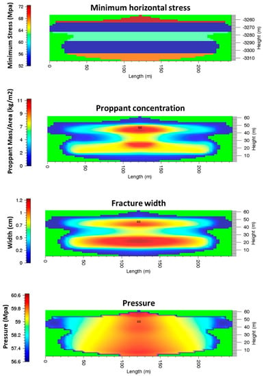
Figure 16.
The stress profile, fracture width, proppant concentration and fluid pressure across the fracture of Case 5.
Compared to Cases 1 to 3, the minimum principal stress of Case 4 and Case 5 is higher, while the shale interlays are thinner, resulting in a different fracture geometry and proppant distribution. The thickness of the upper shale layers and the lower shale layer in Case 4 reduces to 10 m and 12 m, while the minimum principal stress of the shale layers increases. Although the upper and lower sandstone layer can be fractured, the fracture in the two layers is not long, as shown by the results.
5.2. Numerical Study of Multiple Fractures with Realistic Frictions
In this session, we present the numerical study of the simultaneous propagation of three fractures. The fractures are initiated from three neighboring perforations that locate 15 m from each other on a horizontal well (See Figure 17). The horizontal well is drilled within a sandstone layer sandwiched by two shale layers (caprocks).
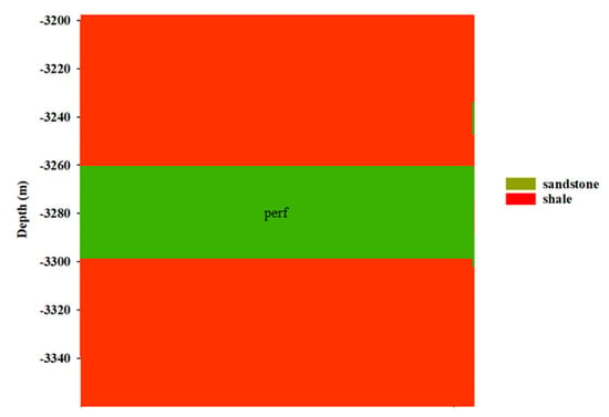
Figure 17.
The profile of the formation for the multiple fracture case.
The rock properties used in this case are the same as those used in Section 4.2, shown in Table 5, except that the minimal principal stress of the sandstone layer and the shale layer is 52 MPa and 62 MPa, respectively. The pumping schedule is listed in Table 7. We assume that all the three perforations are open; therefore, fractures can grow simultaneously.

Table 7.
Pumping schedules of the multiple fracture cases. The stage index refers to the sequence of injected segments.
We use FracCSM to simulate this case and take the stress shadow effect into consideration. In this case, the friction along the wellbore is no more ignored. The 3D view of the resulting three fractures is shown in Figure 18. The deviation profiles of the three fractures are shown in Figure 19. According to the results, with realist frictional force taken into consideration, the multiple simulated fractures are not symmetric, not like that observed in [21,49]. Fracture 3 is longer than Fracture 1 and Fracture 2, because it is in the upstream direction of the injected slurry. The slurry that flows into Fracture 3 has relatively higher energy. This also results in Fracture 3 having less deviation. The comparison of the fracture length with and without the friction within the wellbore is shown in Figure 20, according to which the frictional loss plays an important role in the propagation of multiple fractures.
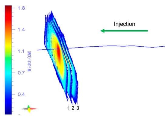
Figure 18.
3D view of the three fractures.
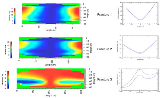
Figure 19.
Deviation of the three fractures. Positive values refer to deviation pointing to the left direction in Figure 18. Left: deviation profile across the fracture plane. Right: top view of the fracture deviation.
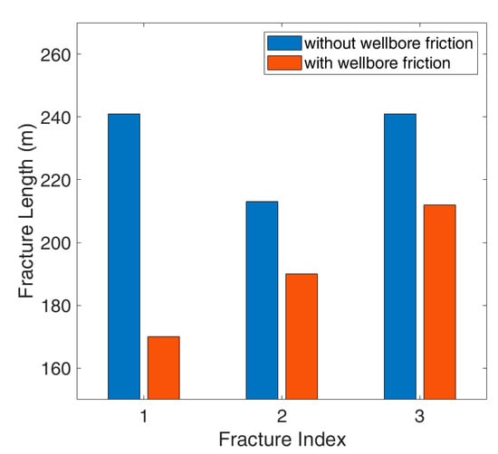
Figure 20.
Comparison between the fracture length with and without the wellbore friction.
5.3. Field Application Results
The real-time simulation module of FracCSM has been successfully applied in Sulige gas field, a tight sandstone gas field in Changqing Reservoir, China.
The hydraulic fracturing facility emits signals every second. The signal is passed to FracCSM through an RS232 data port. FracCSM picks up and interprets the signal to obtain the real-time injection rate, surface pressure, stage index and temperature.
The type of the proppant and the fluid used within each stage is determined by a pre-set pumping schedule input by the user. FracCSM then searches in the database for the properties of the proppant and the fluid. Based on the collected real-time data, FracCSM conducts simulation every four seconds and updates the fracture geometry in the user interface.
FracCSM has been successfully applied to 8 wells in Sulige gas field. The grid block dimension used is 2 m by 1 m. The time lag between the simulation and downhole operations is less than 2 s, which guarantees the early detection of screen-out. For one of the wells, the recorded surface data profile as real-time visualization of the fracture geometry of a slug of proppant is shown in Figure 21. According to the figure, FracCSM captures the transient variation of fracture geometry as well as the variation of proppant distribution. The corresponding video has been uploaded as a Supplementary Material of this paper.

Figure 21.
The real-time simulation of a slug of proppant. The photo was taken at Sulige gas field. (a) Data measured on the ground. The black curve is the real-time proppant concentration measured at the surface. Upper-left in (b) real-time downhole pressure calculated by FracCSM. Upper-right in (b): real-time proppant distribution inside the fracture predicted by FracCSM. Lower-right in (b): real-time width distribution inside the fracture predicted by FracCSM.
The results indicate that FracCSM is able to conduct real-time fracturing simulation smoothly and accurately. Moreover, the net pressure predicted by FracCSM matches real observations well.
5.4. Discussion
We have successfully applied the developed program to both synthetic and real-world cases, which demonstrates the accuracy as well as the flexibility of the proposed approach. Through the numerical experiments, we found that:
- The wellbore friction has a considerable impact on the hydraulic length of the fracture.
- The stress interference effect as well as the leak-off effect both affect the propped length of the fracture, via affecting the fracture width and the proppant-carrying capability of the slurry.
- The multi-process framework shows sound flexibility in dealing with real-time simulations.
In addition to hydraulic fracturing in tight reservoirs, our program also has the potential to be applied to the stimulation of geothermal reservoirs. Moreover, the multi-process framework can also be utilized in other engineering areas where the simulation engine needs to interact with real-time signals.
Admittedly, our program still possesses certain limitations. First of all, our program cannot deal with the interaction between hydraulic fractures with pre-existing natural fractures/joints. Secondly, the proppant transport model is empirical. Recent research [52] has shown that the proppant transport within hydraulic fractures also has the bridging effect. Thirdly, the speed of the program has room to improve. We are working on the parallelization of the simulation engine.
6. Summary and Conclusions
In this work, we have developed a comprehensive simulator FracCSM for practical simulation of hydraulic fracturing operations. This simulator is based on an Integrated Finite Difference and Discontinuous Displacement Method and has been validated by both research code and commercial software. We have formulated a comprehensive model for the mass/energy transport in the wellbore and inside the fracture, including the proppant settling, fluid leak-off and frictional loss effect. We have developed a novel framework to combine IFD and DDM, which suitably takes the advantages of each method. The combined algorithm avoids the discretization of the entire reservoir, which significantly improves its computational speed, enabling it to conduct real-time simulation.
From the numerical study, we can draw the following conclusions:
- Stress offset along with permeability distribution not only affects the fracture propagation, but also the proppant distribution inside the fracture plane. Ignoring the impact of proppant concentration on the fluid flow may lead to overestimation of the propped height.
- The energy loss induced by friction and heat conduction within the wellbore and the formation plays an important role in the simulation of hydraulic fractures. The mass/energy transport must be comprehensively simulated to obtain realistic resutls of single as well as multiple fracture propagation.
- In general, the hydraulic fracturing operations involve complex thermal-hydraulic-mechanical processes, and thus multiphysical simulation techniques are crucial in real practice.
Our program and its results have already been adopted by the users to guide the hydraulic fracturing operations in Sulige gas field. Our program can be further applied to the recovery of unconventional oil/gas reservoirs [53,54].
Supplementary Materials
The following supporting information can be downloaded at: https://www.mdpi.com/article/10.3390/w15050938/s1. Video S1: The real-time simulation module of FracCSM.
Author Contributions
Conceptualization, S.W. and Y.-S.W.; methodology, S.W.; software, P.H.W.; validation, S.W.; writing—original draft preparation, S.W.; writing—review and editing, X.Y.; All authors have read and agreed to the published version of the manuscript.
Funding
This work is financially supported by CNPC-USA with contracted project “Development of 3D Hydraulic Fracturing Simulator for Tight Reservoirs”.
Data Availability Statement
Not Applicable.
Acknowledgments
We would like to express our gratitude to the support from Energi Simulation.
Conflicts of Interest
The authors declare no conflict of interest.
References
- Nordgren, R.P. Propagation of a Vertical Hydraulic Fracture. Soc. Pet. Eng. J. 1972, 12, 306–314. [Google Scholar] [CrossRef]
- Perkins, T.K.; Kern, L.R. Widths of Hydraulic Fractures. J. Pet. Technol. 1961, 13, 937–949. [Google Scholar] [CrossRef]
- Geertsma, J.; De Klerk, F. A Rapid Method of Predicting Width and Extent of Hydraulically Induced Fractures. J. Pet. Technol. 1969, 21, 1571–1581. [Google Scholar] [CrossRef]
- Advani, S.H.; Lee, T.S.; Lee, J.K. Three-Dimensional Modeling of Hydraulic Fractures in Layered Media: Part I—Finite Element Formulations. J. Energy Resour. Technol. 1990, 112, 1. [Google Scholar] [CrossRef]
- Baca, R.G.; Arnett, R.C.; Langford, D.W. Modelling fluid flow in fractured-porous rock masses by finite-element techniques. Int. J. Numer. Methods Fluids 1984, 4, 337–348. [Google Scholar] [CrossRef]
- Chen, Z. Finite element modelling of viscosity-dominated hydraulic fractures. J. Pet. Sci. Eng. 2012, 88–89, 136–144. [Google Scholar] [CrossRef]
- Yang, T.H.; Tham, L.G.; Tang, C.A.; Liang, Z.Z.; Tsui, Y. Influence of Heterogeneity of Mechanical Properties on Hydraulic Fracturing in Permeable Rocks. Rock Mech. Rock Eng. 2004, 37, 251–275. [Google Scholar] [CrossRef]
- Moës, N.; Belytschko, T. Extended finite element method for cohesive crack growth. Eng. Fract. Mech. 2002, 69, 813–833. [Google Scholar] [CrossRef]
- Moes, N.; Dolbow, J.; Belytschko, T. A finite element method for crack growth without remeshing. Int. J. Numer. Methods Eng. 1999, 46, 131–150. [Google Scholar] [CrossRef]
- Sukumar, N.; Moes, N.; Moran, B.; Belytschko, T. Extended finite element method for three-dimensional crack modelling. Int. J. Numer. Methods Eng. 2000, 48, 1549–1570. [Google Scholar] [CrossRef]
- Baghbanan, A.; Jing, L. Hydraulic properties of fractured rock masses with correlated fracture length and aperture. Int. J. Rock Mech. Min. Sci. 2007, 44, 704–719. [Google Scholar] [CrossRef]
- Jing, L.; Stephansson, O. Fundamentals of Discrete Element Methods for Rock Engineering: Theory and Applications, 1st ed.; Elsevier: Amsterdamm, The Netherlands, 2007. [Google Scholar]
- Tan, Y.; Yang, D.; Sheng, Y. Discrete element method (DEM) modeling of fracture and damage in the machining process of polycrystalline SiC. J. Eur. Ceram. Soc. 2009, 29, 1029–1037. [Google Scholar] [CrossRef]
- Li, L.C.; Tang, C.A.; Li, G.; Wang, S.Y.; Liang, Z.Z.; Zhang, Y.B. Numerical Simulation of 3D Hydraulic Fracturing Based on an Improved Flow-Stress-Damage Model and a Parallel FEM Technique. Rock Mech. Rock Eng. 2012, 45, 801–818. [Google Scholar] [CrossRef]
- Tang, C.; Tham, L.; Lee, P.K.; Yang, T.; Li, L. Coupled analysis of flow, stress and damage (FSD) in rock failure. Int. J. Rock Mech. Min. Sci. 2002, 39, 477–489. [Google Scholar] [CrossRef]
- Wang, S.; Lukyanov, A.; Wu, Y.-S. Application of Algebraic Smoothing Aggregation Two Level Preconditioner to Multiphysical Fluid Flow Simulations in Porous Media. In Proceedings of the SPE Reservoir Simulation Conference, Galveston, TX, USA, 10–11 April 2019; Society of Petroleum Engineers: Richardson, TX, USA, 2019. [Google Scholar] [CrossRef]
- Scholtès, L.; Donzé, F.-V. Modelling progressive failure in fractured rock masses using a 3D discrete element method. Int. J. Rock Mech. Min. Sci. 2012, 52, 18–30. [Google Scholar] [CrossRef]
- Azevedo, N.M.; Lemos, J.V. Hybrid discrete element/finite element method for fracture analysis. Comput. Methods Appl. Mech. Eng. 2006, 195, 4579–4593. [Google Scholar] [CrossRef]
- Mahabadi, O.K.; Lisjak, A.; Munjiza, A.; Grasselli, G. Y-Geo: New Combined Finite-Discrete Element Numerical Code for Geomechanical Applications. Int. J. Geomech. 2012, 12, 676–688. [Google Scholar] [CrossRef]
- Munjiza, A.; Owen, D.R.J.; Bicanic, N. A combined finite-discrete element method in transient dynamics of fracturing solids. Eng. Comput. 1995, 12, 145–174. [Google Scholar] [CrossRef]
- Wu, K.; Olson, J.E. Simultaneous Multifracture Treatments: Fully Coupled Fluid Flow and Fracture Mechanics for Horizontal Wells. SPE J. 2015, 20, 337–346. [Google Scholar] [CrossRef]
- Wu, K.; Olson, J.E. Mechanics Analysis of Interaction Between Hydraulic and Natural Fractures in Shale Reservoirs. In Proceedings of the Unconventional Resources Technology Conference (URTEC), Denver, CO, USA, 25–27 August 2014. [Google Scholar] [CrossRef]
- Wu, K.; Olson, J.E. Investigation of the Impact of Fracture Spacing and Fluid Properties for Interfering Simultaneously or Sequentially Generated Hydraulic Fractures. SPE Prod. Oper. 2013, 28, 427–436. [Google Scholar] [CrossRef]
- Guo, X.; Wu, K.; An, C.; Tang, J.; Killough, J. Numerical Investigation of Effects of Subsequent Parent-Well Injection on Interwell Fracturing Interference Using Reservoir-Geomechanics-Fracturing Modeling. SPE J. 2019, 24, 1884–1902. [Google Scholar] [CrossRef]
- Kresse, O.; Cohen, C.; Weng, X.; Wu, R.; Gu, H. Numerical Modeling of Hydraulic Fracturing In Naturally Fractured Formations. 2011. Available online: https://onepetro.org/ARMAUSRMS/proceedings-abstract/ARMA11/All-ARMA11/ARMA-11-363/120401 (accessed on 7 January 2023).
- Weng, X. Modeling. of complex hydraulic fractures in naturally fractured formation. J. Unconv. Oil Gas Resour. 2015, 9, 114–135. [Google Scholar] [CrossRef]
- Weng, X.; Kresse, O.; Cohen, C.E.; Wu, R.; Gu, H. Modeling of Hydraulic Fracture Network Propagation in a Naturally Fractured Formation. In SPE Hydraulic Fracturing Technology Conference; Society of Petroleum Engineers: Richardson, TX, USA, 2011. [Google Scholar] [CrossRef]
- Li, Q.; Wang, F.; Wang, Y.; Bai, B.; Zhang, J.; Lili, C.; Sun, Q.; Wang, Y.; Forson, K. Adsorption behavior and mechanism analysis of siloxane thickener for CO2 fracturing fluid on shallow shale soil. J. Mol. Liq. 2023, 376, 121394. [Google Scholar] [CrossRef]
- Li, Q.; Wu, J. Factors affecting the lower limit of the safe mud weight window for drilling operation in hydrate-bearing sediments in the Northern South China Sea. Geomech. Geophys. Geo. Energy Geo. Resour. 2022, 8, 82. [Google Scholar] [CrossRef]
- Yew, C.H.; Weng, X. Mechanics of Hydraulic Fracturing, 2nd ed.; Gulf Professional Publishing: Waltham, MA, USA, 2015. [Google Scholar]
- Olson, J. Fracture Mechanics Analysis of Joints and Veins; Stanford University: Stanford, CA, USA, 1991. [Google Scholar]
- Sheibani, F. Solving Three-Dimensional Problems in Natural and Hydraulic Fracture Development: Insight from Displacement Discontinuity Modeling; UT Austin: Austin, TX, USA, 2013. [Google Scholar]
- Mastrojannis, E.N.; Keer, L.M.; Mura, T. Growth of planar cracks induced by hydraulic fracturing. Int. J. Numer. Methods Eng. 1980, 15, 41–54. [Google Scholar] [CrossRef]
- Tang, H.; Wang, S.; Zhang, R.; Li, S.; Zhang, L.; Wu, Y.-S. Analysis of stress interference among multiple hydraulic fractures using a fully three-dimensional displacement discontinuity method. J. Pet. Sci. Eng. 2019, 179, 378–393. [Google Scholar] [CrossRef]
- Wu, Y.S. Hydraulic Fracture Modeling; Gulf Professional Publishing: Oxford, UK, 2017. [Google Scholar]
- Friehauf, K.E. Simulation and Design of Energized Hydraulic Fractures; The University of Texas at Austin: Austin, TX, USA, 2009. [Google Scholar]
- Wang, Y.; Ju, B.; Wang, S.; Yang, Z.; Liu, Q. A tight sandstone multi-physical hydraulic fractures simulator study and its field application. Petroleum 2019, 6, 198–205. [Google Scholar] [CrossRef]
- Nicodemo, L.; Nicolais, L.; Landel, R.F. Shear rate dependent viscosity of suspensions in newtonian and non-newtonian liquids. Chem. Eng. Sci. 1974, 29, 729–735. [Google Scholar] [CrossRef]
- Schechter, R.S. Oil Well Stimulation, 1st ed.; Prentice Hall Inc.: Old Tappan, NJ, USA, 1992. [Google Scholar]
- Economides, M.J.; Nolte, K.G. Reservoir Stimulation, 3rd ed.; Prentice Hall Inc.: Old Tappan, NJ, USA, 2000. [Google Scholar]
- Carslaw, H.S.; Jaeger, J.C. Conduction of Heat in Solids, 2nd ed.; Clarendon Press: Oxford, UK, 1959. [Google Scholar]
- Valko, P.; Economides, M.J. Hydraulic Fracture Mechanics; JOHN WILEY & SONS: New York, NY, USA, 1995. [Google Scholar]
- Narasimhan, T.N.; Witherspoon, P.A. An integrated finite difference method for analyzing fluid flow in porous media. Water Resour. Res. 1976, 12, 57–64. [Google Scholar] [CrossRef]
- Bonduà, S.; Battistelli, A.; Berry, P.; Bortolotti, V.; Consonni, A.; Cormio, C.; Geloni, C.; Vasini, E.M. 3D Voronoi grid dedicated software for modeling gas migration in deep layered sedimentary formations with TOUGH2-TMGAS. Comput. Geosci. 2017, 108, 50–55. [Google Scholar] [CrossRef]
- Hu, L.; Zhang, K.; Cao, X.; Li, Y.; Guo, C. IGMESH: A convenient irregular-grid-based pre- and post-processing tool for TOUGH2 simulator. Comput. Geosci. 2016, 95, 11–17. [Google Scholar] [CrossRef]
- Wang, S.; Huang, Z.; Wu, Y.-S.; Winterfeld, P.H.; Zerpa, L.E. A semi-analytical correlation of thermal-hydraulic-mechanical behavior of fractures and its application to modeling reservoir scale cold water injection problems in enhanced geothermal reservoirs. Geothermics 2016, 64, 81–95. [Google Scholar] [CrossRef]
- Wang, S.; Xiong, Y.; Winterfeld, P.; Zhang, K.; Wu, Y.-S. Parallel Simulation of Thermal-Hydrological-Mechanic (THM) Processes in Geothermal Reservoirs. In Proceedings of the 39th Workshop on Geothermal Reservoir Engineering, Stanford, CA, USA, 24–26 February 2014; Stanford University: Stanford, CA, USA, 2014. [Google Scholar]
- Crouch, S.L. Solution of plane elasticity problems by the displacement discontinuity method. I. Infinite body solution. Int. J. Numer. Methods Eng. 1976, 10, 301–343. [Google Scholar] [CrossRef]
- Tang, H.; Winterfeld, P.H.; Wu, Y.-S.; Huang, Z.; Di, Y.; Pan, Z.; Zhang, J. Integrated simulation of multi-stage hydraulic fracturing in unconventional reservoirs. J. Nat. Gas Sci. Eng. 2016, 36, 875–892. [Google Scholar] [CrossRef]
- Ribeiro, L.; Sharma, M.M. A New Three-Dimensional, Compositional, Model for Hydraulic Fracturing with Energized Fluids. In Proceedings of the SPE Annual Technical Conference and Exhibition, San Antonio, TX, USA, 8–10 October 2012; Society of Petroleum Engineers: Richardson, TX, USA, 2012. [Google Scholar] [CrossRef]
- CARBO. FRACPRO Fracture Design &. Analysis Software; Pinach. Inc.: Denver, CO, USA, 2019. [Google Scholar]
- Barboza, B.R.; Chen, B.; Li, C. A review on proppant transport modelling. J. Pet. Sci. Eng. 2021, 204, 108753. [Google Scholar] [CrossRef]
- Wang, L.; Tian, Y.; Yu, X.; Wang, C.; Yao, B.; Wang, S.; Winterfeld, P.H.; Wang, X.; Yang, Z.; Wang, Y.; et al. Advances in improved/enhanced oil recovery technologies for tight and shale reservoirs. Fuel 2017, 210, 425–445. [Google Scholar] [CrossRef]
- Wang, L.; Wang, S.; Zhang, R.; Wang, C.; Xiong, Y.; Zheng, X.; Li, S.; Jin, K.; Rui, Z. Review of multi-scale and multi-physical simulation technologies for shale and tight gas reservoirs. J. Nat. Gas Sci. Eng. 2017, 37, 560–578. [Google Scholar] [CrossRef]
Disclaimer/Publisher’s Note: The statements, opinions and data contained in all publications are solely those of the individual author(s) and contributor(s) and not of MDPI and/or the editor(s). MDPI and/or the editor(s) disclaim responsibility for any injury to people or property resulting from any ideas, methods, instructions or products referred to in the content. |
© 2023 by the authors. Licensee MDPI, Basel, Switzerland. This article is an open access article distributed under the terms and conditions of the Creative Commons Attribution (CC BY) license (https://creativecommons.org/licenses/by/4.0/).