Article

Numerical Modelling of Beach Profile Evolution with and without an Artificial Reef

1
College of Civil Engineering, Tongji University, Shanghai 200092, China
2
State Key Laboratory of Marine Geology, Tongji University, Shanghai 200092, China
3
The Lyell Centre for Earth and Marine Science and Technology, Institute for Infrastructure and Environment, Heriot-Watt University, Edinburgh EH14 4AS, UK
*
Authors to whom correspondence should be addressed.
Water 2023, 15(21), 3832; https://doi.org/10.3390/w15213832
Submission received: 29 September 2023 / Revised: 23 October 2023 / Accepted: 27 October 2023 / Published: 2 November 2023

Abstract

:
With the recent development from grey infrastructures to green infrastructures, artificial reefs become more popular in coastal protection projects. To investigate the responses of beach profile evolution to the presence of an artificial reef, a non-hydrostatic model is established. Both hydrodynamic and morphodynamic evolution for the beach with and without an artificial reef are compared under regular wave conditions. In addition, the protected beach profile evolution by an artificial reef is discussed under irregular wave conditions. Three key parameters in non-hydrostatic simulation are considered for sensitivity analysis, including maximum wave steepness criterium (maxbrsteep), water depth factor (depthscale), and equilibrium sediment concentration factor (sedcal). The numerical results under regular wave conditions indicate that the artificial reef enhances wave attenuation by inducing wave breaking. In addition, the artificial reef reduces local flow velocity and offshore sediment transport by 51%, therefore decrease the total erosion by 53%. Over the artificial reef, wave skewness and asymmetry go through a drastic change. Under irregular wave conditions, short waves contribute to the wave energy mainly and reflection-induced standing wave effects decline considerably. It demonstrates that the artificial reef can protect the beach from regular and irregular waves by reducing erosion and offshore transport of suspended sediments. Moreover, in the wave breaking area, the increase of maximum wave steepness criterium may give arise to the wave height. The morphological evolution is more sensitive to water depth factor than equilibrium sediment concentration factor, because the former is a controlling factor for beach profile characteristics while the latter forms the sandbar varying irregularly in shape.

1. Introduction

Coastal erosion and recession threaten public and property safety and restrict coastal developments. To address these issues, governments spare no effort to protect the coastlines with various coastal defence techniques and structures. Hard engineering solutions can provide direct defences for eroded coasts, but such structures alter the sediment transport and morphological evolution irreversibly [1,2,3,4]. Moreover, these constructions may damage the natural habits and cause the ecological degradation [5,6]. In recent decades, soft engineering solutions have been used to harmonize hydrodynamic conditions and ecological environments in coastline protections and restorations. Therefore, coastal protections are subject to a great transformation from grey infrastructures to green infrastructures [7,8]. Among the soft engineering solutions, beach nourishment has become a mature technology after a centurial development since 1920s [9,10,11]. Meanwhile, the extended applications of this approach, such as sandbars and sand engines, have gained popularity in practices [12,13,14,15]. Nowadays, artificial reefs play an important role in beach nourishment for its potential in ecosystem service [16,17]. When it comes to morphological evolution under the coastal protection by soft engineering solutions, nourished beaches and artificial reefs are treated as an integral system in general. Nevertheless, the structural functions of artificial reefs ought to be considered, because nourished beaches and artificial reefs plays different roles in coastal protections. In particular, beach nourishment is utilized to feed the beach, whereas artificial reefs attenuate waves to mitigate erosions.
Traditional artificial reefs can decelerate flow and provide shelters for local communities to inhabit. For box-type artificial reefs, cut-opening ratio dominates the upwelling and back eddy [18,19,20], and the aspect ratio of reef arrangements affects the internal turbulence [21]. Incident angle, spacing distance and upper surface rugosity of untraditional artificial reefs may alter the wake region as well [22,23,24,25,26]. Furthermore, artificial reefs can protect the coast from excessive erosions indirectly. To better understand the hydrodynamic and morphodynamic responses to artificial reefs, physical models and laboratory-scale numerical models have been adopted. Based on a series of experiments on flow structure and sediment transport around artificial reefs under pure current conditions, Shu et al. revealed that sediments can hardly suspend in the area occupied by artificial reefs, while sediments between the artificial reefs are more likely to move [27,28]. Through laboratory experiments and numerical modelling, Zhang found that the edge scours along box-type artificial reefs are more intensive than the bed scours inside, and depositions occur in the wake region mainly [29], which is consistent with the experimental results by Tang et al. [30]. Previous studies focused more on local impacts of artificial reefs, with little attentions to wave actions on the sheltered beaches. However, wave-induced erosion is a predominant hazard for sandy beaches [31,32].
Unlike laboratory-scale numerical models, field-scale numerical models are capable to assess the regional influences of artificial reefs. Wu’s numerical results on the sediment transport in an artificial reef area in Zhoushan, China, demonstrated that artificial reefs have limited effects on sediment movement and bed scour under current actions [33]. Guilherme et al. investigated the morphological evolution around the multi-purpose artificial reefs along the Gold Coast of Australia using numerical modelling [34]. They found that littoral sediment transport causes great accretions in the wave shadow area, and the artificial reefs can trap the sediment and stabilize the sandbar. Similarly, the artificial reefs along Rhode Island, USA was found to dissipate wave energy and mitigate current conditions as well [35]. According to the experimental results by Yang et al., the combination of a gravel dam and artificial reefs can maximize the protection for eroded beaches [36]. Kuang et al. and Ma et al. investigated the cross-shore hydrodynamic and morphodynamic evolution under regular waves and irregular waves [37,38]. They conducted a series of experiments to distinguish the protection of nourished beach, artificial sandbar and artificial reef, with special attentions to the impacts of artificial reefs on wave attenuation and dissipation. Meanwhile, the artificial reefs may reform the scarp on a nourished beach. Artificial reefs act as an important component in coastal protection projects. Therefore, investigations on nourished beach profile evolution with and without artificial reef are practically important. Based on the experimental results by Ma et al., it is necessary to establish a numerical model to get more detailed hydrodynamic, sediment transport and morphodynamic results which is hard to measure in the physical experiment to improve the understanding of the hydrodynamic and morphodynamic responses to artificial reefs.
In the present study, a reduced two-layer non-hydrostatic model is established by XBeach to investigate nourished beach profile evolution under regular wave conditions. To pinpoint the driving mechanisms of flow structure, wave propagation, sediment transport and morphological evolution, numerical results of the beach with and without an artificial reef are compared. In addition, the effects of irregular waves are taken into considerations. Furthermore, sensitive analysis is conducted to examine the influences of three key parameters on the problem. The main objective is to reveal the impacts of artificial reefs on beach profile evolution and assess the performance of a reduced two-layer non-hydrostatic model in simulating wave-dominated beaches in the field.

2. Methodology

2.1. Numerical Model

To investigate beach profile evolution under the protection of an artificial reef, a non-hydrostatic model is established by XBeach [39]. To resolve the wave dispersive issue of non-hydrostatic models, the reduced two-layer mode is utilized to improve the non-hydrostatic simulations [40,41,42,43]. The details of reduced two-layer non-hydrostatic models are specified as follows. More information can be referred online (https://xbeach.readthedocs.io/en/latest/index.html (accessed on 26 September 2023)).
In the non-hydrostatic XBeach model, the depth-averaged normalized dynamic pressure is derived in a similar fashion as the one-layer version of the SWASH model [44], so that the one-dimensional non-linear shallow water equations are given by
η t + h u x = 0
u t + u u x = g η x 1 h d η q x d z + ν h 2 u x 2 c f u u h
where η is the water level; d is the still water depth, h is the total water depth, h = η + d ; u represents the velocity in x-direction; g is the gravity constant; ν h is the horizontal viscosity; p is the dynamic pressure; q is the normalized dynamic pressure by the water density ρ , q = p / ρ ; c f is the dimensionless friction coefficient. The depth averaged dynamic pressure is computed assuming a linear vertical distribution of dynamic pressure with zero value at the surface.
d η q x d z = x d η q d z q z = η η x + q z = d d x = 1 2 h q z = d x + q z = d d x = 1 2 h q z = d x + 1 2 q z = d η d x = 1 2 h q b x + 1 2 q b η d x
where q b is the normalized dynamic pressure at the bed. Stelling and Zijlema [45] applied the Keller-box method [46] to obtain the pressure gradient in the vertical, and then q b can be described as,
q b = h 2 ( q z z = η + q z z = d )
In order to compute the normalized dynamic pressure at the bed, the contributions of advective and diffusive terms to the vertical momentum balance are assumed to be negligible.
w s t + q z z = η = 0 w b t + q z z = d = 0
where w s is the vertical velocity at the surface and w b is the vertical velocity at the bed. Then q b can be described as,
q b = h 2 ( w s t + w b t )
The vertical velocity at the bed is set by the kinematic boundary condition.
w b = u d x
Thus, the local continuity equation equation is given by
u x + w s w b h = 0
The reduced two-layer model assumes that the non-hydrostatic pressure is constant in the lower layer. This means that the non-hydrostatic pressure at the bottom has the same value as the non-hydrostatic pressure between the layers. To simplify the reduced layer, the layer velocities are converted into a depth-averaged velocity u and a velocity difference Δ u by
u l o w e r u u p p e r = 1 1 α 1 α u Δ u
u Δ u = α 1 α 1 1 u l o w e r u u p p e r
where u l o w e r and u u p p e r represents the velocity in the lower and upper layer; α is the layer distribution, α = h l o w e r / h ; h l o w e r is the water depth of the lower layer. Therefore, the momentum equations are given by [42,43],
h u t + g h η x + x h u 2 + 1 + α 2 h q b x q b d x = 0
h Δ u t + h u Δ u x + 1 2 h q b x + q b ( 1 α ) η x = τ b ν 2 Δ u α ( 1 α ) h
h w s t + h u w s x q b ( 1 α ) = 0
where τ b represents the bed shear stress; ν is the kinematic viscosity. Due to the simplified non-hydrostatic pressure in the lower layer, the vertical velocity between the layers is neglected. Thus, only the continuity equation for the upper layer is required,
( 1 + α ) h u x + α α 2 h Δ u x + 2 w s u s η x u z α z α x = 0
where z α is the height of interface, z α = α h d ; u s represents the vertical velocity at the surface; u z α represents the velocity in x-direction at the surface. Based on the global continuity equation (Equation (1)), the water elevation can be determined.
The numerical modelling in the present study is set up based on the experiments on beach profile evolutions by Ma et al. [38] in a wave flume. The flume is 50 m in length, 0.8 m in width and 1.2 m in depth. Figure 1 shows the beach with and without an artificial reef after beach nourishment. The beach slope is 1:10. The water depth is 0.5 m. The artificial reef is 1.8 m long and 0.3 m high. The median grain size of model sand is 0.17 mm. Based on the experimental set-up, two types of beach profiles are established by one-dimensional grid system. The grid is 22 m in length, including the buffer area of 10 m before the origin x = 0, and the study area of 12 m. The resolution of the buffer area is 0.05 m, and the grid is refined in the study area to 0.02 m. There are 762 grid cells in total.
The model is driven by wave, flow and tide at the offshore boundary. The wave boundary condition is specified as constants under regular wave conditions, and defined by JONSWAP spectrum to generate irregular wave conditions. For lateral wave boundaries, Neumann boundary conditions are activated, where the longshore water level gradient is 0. Absorbing-generating boundary conditions are used for flow in weakly-reflective conditions. The lateral flow boundaries are set as no flux walls. The tide boundary is set as uniform water level of 0.5 m.

2.2. Parameter Setting

The simulation lasts 1320 s, including 1320 timesteps. As the cut-off values, the water depth factor (depthscale) is set as 50, the maximum wave steepness criterium (maxbrsteep) is 0.4 and the equilibrium sediment concentration factor (sedcal) is 1. The bed friction coefficient is 0.01. The median grain size D50 is 0.00017 m. The porosity and sediment density are set as 0.4 and 1430 kg/m3, respectively. The morphological acceleration factor is 1 as default. The critical avalanching slope under water and above water are 0.2 and 30, respectively. The beach slope is 1:10. The wave height and wave period under regular waves conditions are 0.1 m and 1.57 s. For comparison, the significant wave height and peak wave period under irregular wave conditions are 0.1 m and 1.57 s as well.

2.3. Validation

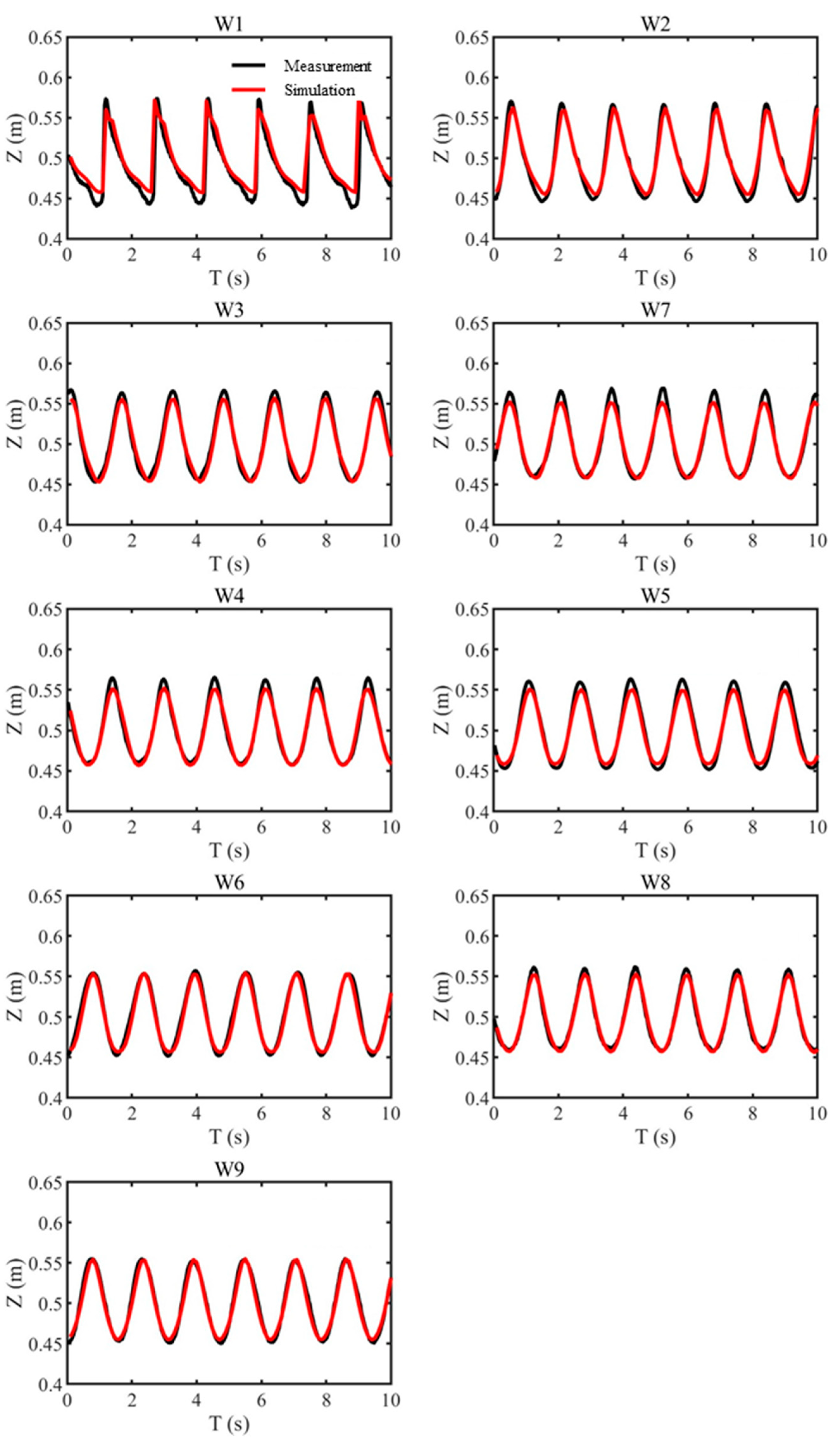
The model predicted wave surface and morphology are validated against the experimental results by Ma et al. [38], for the beach without the artificial reef under regular wave conditions. Figure 2 shows the validation of the predicted wave surface profile time series by the non-hydrostatic model for a duration of 10 s starting at 60 s after the test began. After wave propagation from the offshore area wave W9 to the wave breaking area W1, the regular sine waves shape has changed to steepening crests and widening troughs. At W9, the foreslope of crest is steep and the backslope of crest is mild, so the wave surface is jagged, which illustrates that both wave skewness and asymmetry intensify during the propagation.
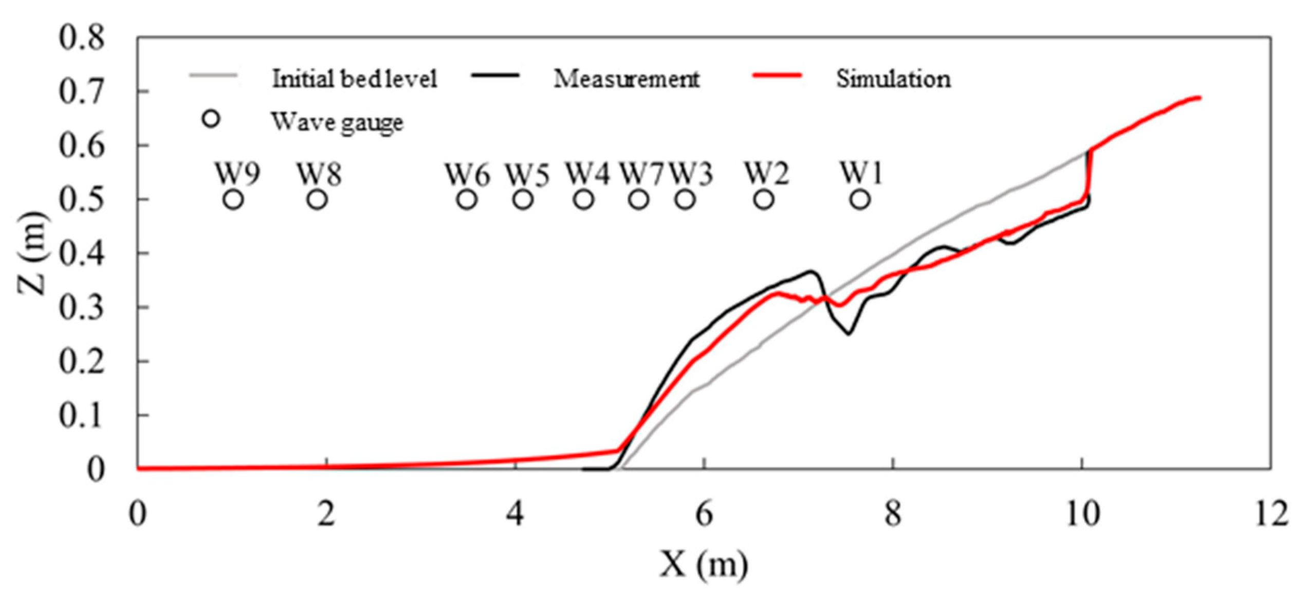
The beach profile at in the end of non-hydrostatic simulation is validated in Figure 3. The morphology has become a sandbar-trough-scarp profile. The wave-induced ero-sion creates a scarp at the waterline and causes suspended sediments transport through backwash. Then a sandbar occurs at the same position of wave breaking point due to the accretions. Meanwhile, a trough on the landward side of the sandbar is formed by plunging waves. The simulated results agree well with the experimental results in terms of the characteristics of beach profile.
The d model is applied to evaluate the performance of the non-hydrostatic model [47]. The d value is calculated by
d = 1 i = 1 n O i P i 2 i = 1 n P i O ¯ + O i O ¯ 2
where O and P are the simulation and observation data, respectively; O ¯ is the average of the observation data; n is the number of observation data. The d value ranges from 0 to 1, where 0.65–1.0, 0.5–0.65, 0.2–0.5, 0–0.2 stands for excellent; very good; good; and poor model-data agreement. Table 1 shows the excellent performance of the non-hydrostatic XBeach model in simulations of hydrodynamic and morphodynamic evolution.

3. Results

The protecting effects of artificial reefs are investigated by hydrodynamic characteristics, sediment transport, and beach profile evolution under regular wave conditions. The numerical results for the bare beach and the protected beach are compared for qualitative and quantitative analysis.

3.1. Hydrodynamic Characteristics

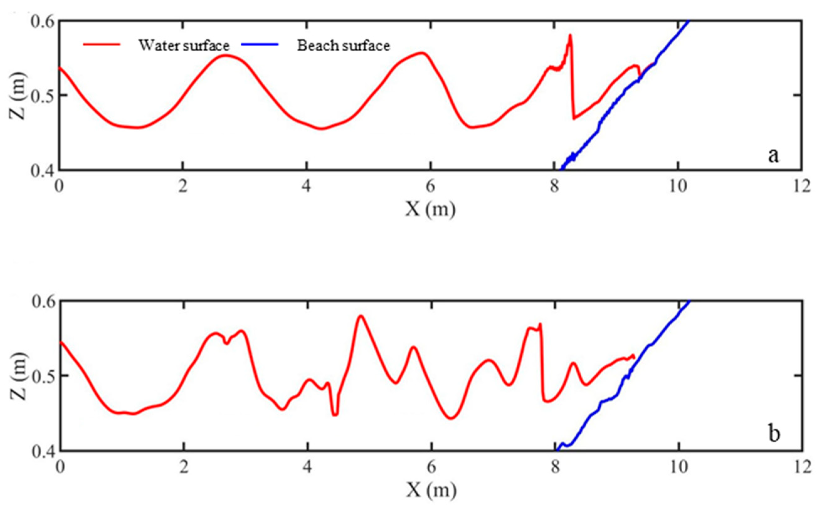
The wave surfaces profile along the two beach profiles at 60 s is shown in Figure 4. As shown in Figure 4a, regular waves are present in the offshore area (x = 0–5.2 m). Then wave crest steepens and wave trough widens in the shallow water (x > 5.2 m). Also, the foreslope of wave profile becomes steep while the backslope becomes mild. After wave breaking, waves reach the swash zone, where uprush and backwash occur alternatively, so the waterline fluctuates up and down. For the beach with the artificial reef (Figure 4b), the artificial reef induces wave breaking earlier (x = 2.7–4.5 m) and breaks the regular waves into the double-crest waves. With the increase of water depth after the artificial reef, the double-crest waves further develop, where the front crest is smaller than the back crest. Under this circumstance, the wave foreslope becomes mild, while the wave backslope becomes steep. Due to shallow water effects, the front crest fully grows and once its foreslope reaches the critical value (maxbrsteep = 0.4), the fore crest breaks first. In the swash area, the waterline also fluctuates up and down due to alternating uprush and backwash.
Wave skewness and wave asymmetry evolve with the wave surface profile due to wave transformation over the beach and the artificial reef. For the beach without the artificial reef (Figure 5a), both wave skewness and wave asymmetry are close to 0 in the offshore area (x = 0–5.2 m). As water depth decreases, wave skewness rises to the peak value over the sandbar at x = 8.2 m. Meanwhile, wave asymmetry is a negative value, which decreases rapidly for shallow water effects, and reach the peak over the trough at x = 8.4 m. Then both wave skewness and wave asymmetry maintain their peak values with oscillations. The oscillations may come from the wave reflection and the associated standing waves. Wave skewness represents the asymmetry of velocity, while wave asymmetry stands for the asymmetry of acceleration. Thus, there is a quarter phase difference between their oscillations. In Figure 5b, the artificial reef causes further wave reflection and associated standing waves, where wave skewness and wave asymmetry show sine-like or cosine-like oscillations. During the wave propagation, the water depth decreases at the artificial reef top (x = 2.7–4.5 m), and then recovers before the beach. In this condition, wave skewness rises first, and then decreases over the recovered water depth on the landward side of the artificial reef (x > 4.5 m). After that, wave skewness increases again due to shallow water effects over the beach. The cross-shore variation of wave asymmetry is almost contrary to wave skewness. Thus, the foreslope and backslope of wave crest vary significantly during the wave propagation.
The cross-shore evolution trend of wave skewness and asymmetry over the artificial reef is similar to that over a low-crested structure (LCS) using a 2-D RANS-VOF model and laboratory observations by Zou & Peng [48] and Peng et al. [49]. It was found that wave reflection increases/decreases the magnitude of wave skewness and wave asymmetry on the incident/transmission side of LCS. According to the bispectral analysis by Zou & Peng [48], the observed wave shape evolution over a LCS can be attributed to the changes in the interplay of sum and difference nonlinear wave-wave interactions. Besides the cross-shore wave height transformation, mean flow, wave skewness and asymmetry are the major drivers for beach morphological change with and without low crest structure such as sand bar, natural and artificial reef and breakwater [50,51,52,53].
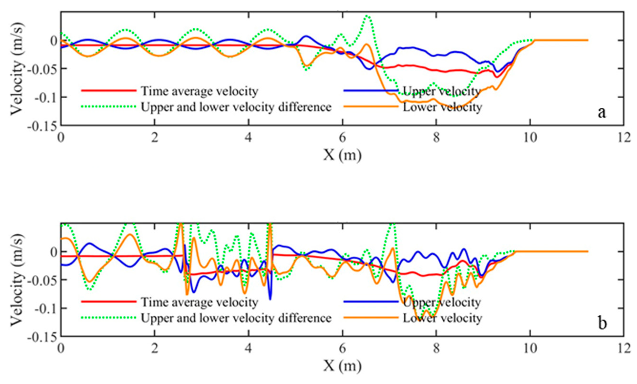
Time average velocity, upper layer and lower layer flow velocity and their difference are shown in Figure 6. For the beach without the artificial reef (Figure 6a), time average velocity in offshore area is close to 0, so waves remain sinusoidal. Standing waves due to wave reflection lead to sine-like or cosine-like oscillations in upper and lower velocity. In the shallow water area (x > 5.2 m), time average velocity is negative and its absolute value rises first and then decreases. Moreover, the lower layer flow is more intensive than the upper layer flow, and both of them have an offshore trend. Figure 6b illustrate that the artificial reef alters the local flow structures considerably. On seaward side of the artificial reef (x < 2.7 m), time average velocity is 0, but upper and lower velocity and their difference are characterized with oscillations due to wave reflection. On the artificial reef top (x = 2.7–4.5 m), the time average velocity is relatively steady, while the upper and lower velocity vary irregularly. In the shallow water area (x > 5.2 m), time average velocity rises first and then declines, where the negative offshore flow is much more intensive in the lower layer than the upper layer.

3.2. Sediment Transport

As shown in Figure 7, for both beach profiles, the suspended load transport rates are negative, while the bedload transport rates are positive, i.e., suspended load transport is offshore and bedload transport is onshore. In Figure 7a, the maximum suspended load transport rate is 7.3 × 10⁻⁵ m2/s, but the maximum bedload transport rate is 4.9 × 10⁻⁷ m2/s which is much less than the suspended load transport. Thus, the suspended load transport plays a predominant role in beach profile evolution. In Figure 7b, the maximum suspended load transport rate decreases to 3.6 × 10⁻⁵ m2/s in the presence of the artificial reef, i.e., the artificial reef reduces the offshore flow and suspended load transport by 51%.

3.3. Morphological Evolution

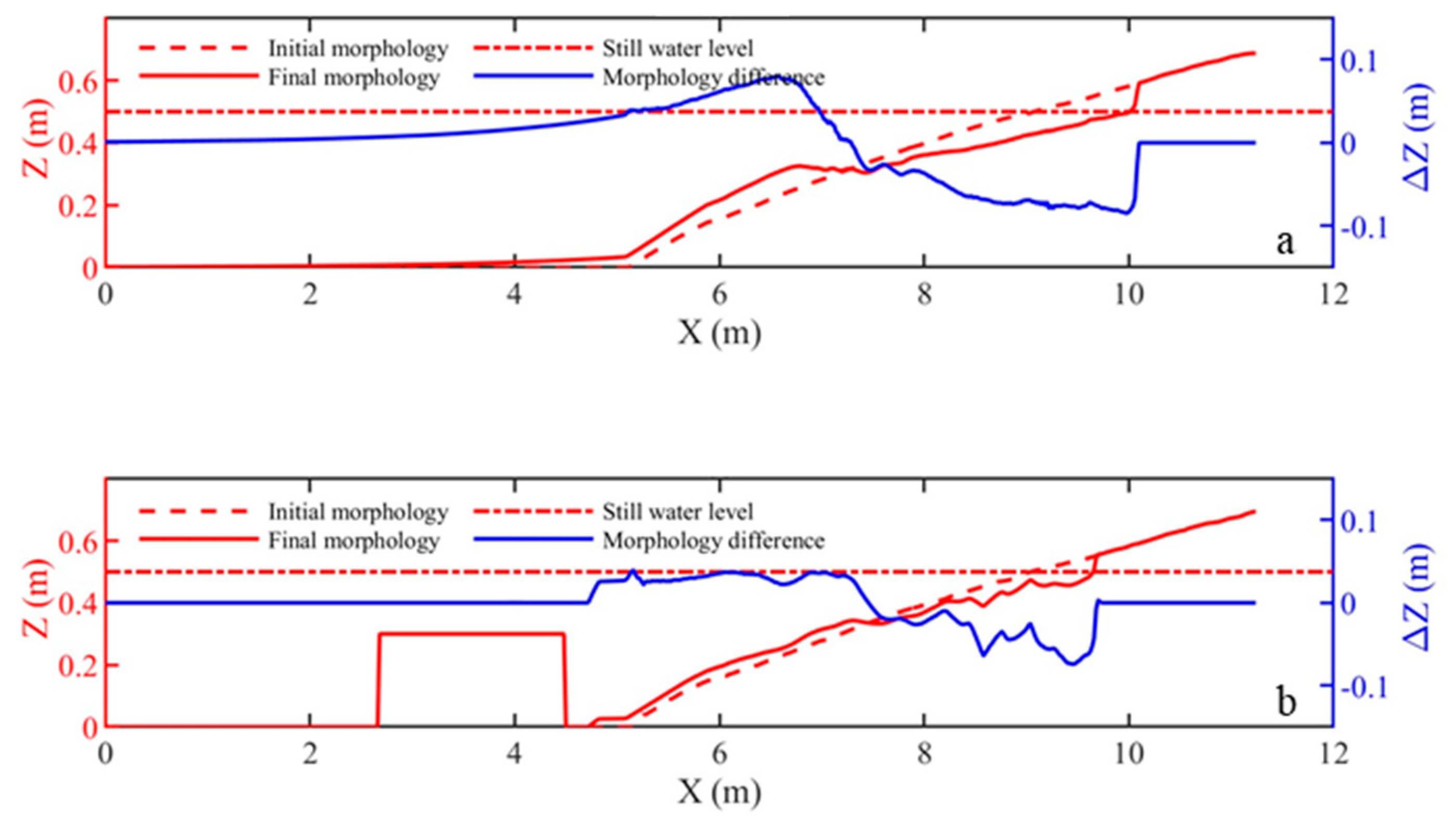
Figure 8 shows the initial and the final morphology and their difference. The final morphology is characterized by a sandbar-trough-scarp profile. The wave-induced erosion generates a scarp at the waterline. The suspended sediments transport offshore with the backwash. At the wave breaking point, the sediment deposition forms a sandbar. Then plunging waves contribute to the trough on the landward side of the sandbar. In fact, the variation of bed level is related to the cross-shore transport gradient. As shown in Figure 8a, the critical deposition point of final morphology occurs at the position (x = 7.3 m) where the maximum suspended load transport rate occurs, whose cross-shore gradient is 0. Meanwhile, the sandbar crest is located at the position (x = 6.7 m) where the maximum cross-shore gradient of suspended load transport rate is. Under this circumstance, it is evident that suspended load dominates the beach profile evolution. The maximum erosion depth occurs at the scarp, which decreases from 0.08 m to 0.07 m by 13% for additional protection by the artificial reef. Moreover, the artificial reef reduces the total erosion amount per unit width from 0.17 m2 to 0.08 m2 by 53%.

4. Discussion

Based on the non-hydrostatic simulation under irregular wave conditions, hydrodynamic and morphodynamic evolution of the protected beach are discussed. In addition, sensitivity analysis is utilized to figure out the impacts of three key model parameters on non-hydrostatic simulation using XBeach model.

4.1. Irregular Wave Effects

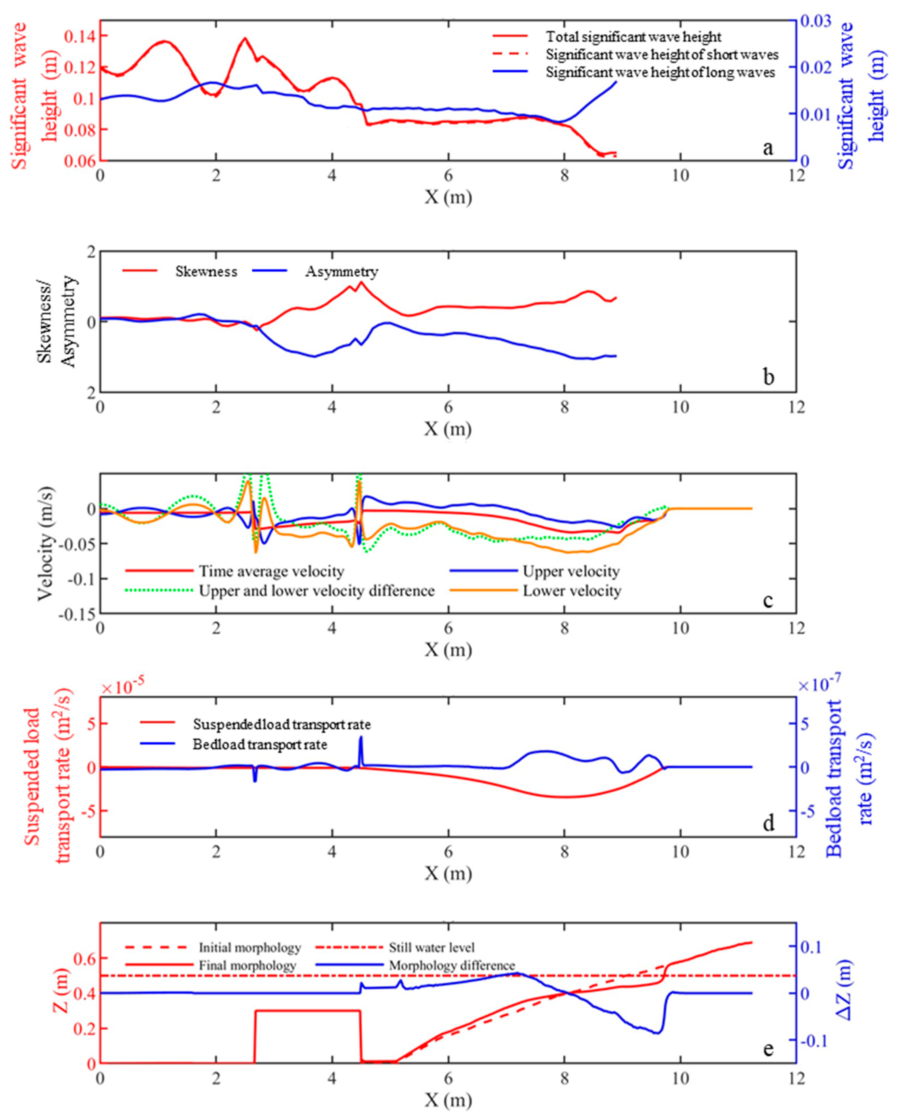
The beach profile evolution under irregular wave conditions is related to cross-shore significant wave height, wave skewness, wave asymmetry, flow structure, sediment transport and bed level changes. Figure 9 shows the numerical results in non-hydrostatic simulation for the beach with the artificial reef under irregular wave conditions. In Figure 9a, total significant wave height corresponds to short wave significant wave height, because short waves (0.15–3.16 Hz) contribute to the wave energy mainly, and a small part of energy is transferred to long waves (0.01–0.15 Hz) because of wave breaking. The artificial reef results in standing waves due to wave reflection, whose influences decline with the increasing distance to the artificial reef. Such characteristics are consistent with the theoretical and measured values by Goda et al. [54]. On the artificial reef top (x = 2.7–4.5 m), total significant wave height and the significant wave height of short waves declines rapidly, so the artificial reef has a significant effect on wave attenuations. Then shallow water result in an increase in wave height, but the significant wave height declines due to wave breaking. Simultaneously, the increased long waves are resulted from wave breaking through roller-induced radiation stress. As shown in Figure 9b, the cross-shore wave skewness and asymmetry are similar to those under regular wave conditions (Figure 5b). However, the oscillation is reduced under the irregular wave conditions because the standing wave effects induced by the wave reflection decline considerably.
The time average velocity, upper and lower velocity are smoother under irregular wave conditions (Figure 9c). The time average velocity in the offshore area is 0, while the upper and lower velocity oscillate due to the wave reflection by the artificial reef, and varies with the distance to the artificial reef. On the artificial reef top (x = 2.7–4.5 m), the time average velocity is negative, where both the upper and lower flow are offshore. Then the time average velocity recovers to 0, but then becomes negative in the shallow water area. Similar to the phenomena under regular wave conditions (Figure 6b), the lower offshore flow is more intensive than the upper offshore flow.
The cross-shore sediment transport rates are similar to those under regular wave conditions (Figure 7b), i.e., the suspended load transport dominates the beach profile evolution. In Figure 9d, the maximum suspended load transport rate is around 3.4 × 10⁻⁵ m2/s. Therefore, the artificial reef reduces the offshore sediment transport effectively under both regular and irregular waves conditions. The final morphology in Figure 9e is characterized by a terrace-scarp profile. Compared with the morphology under regular wave conditions, the moving breaking point of irregular waves can hardly form the fixed trough and sandbar observed for regular waves anymore. The total erosion amount per unit width is 0.08 m2 under irregular wave conditions. Therefore, the artificial reef provides positive and persistent protection from excessive erosions.

4.2. Sensitivity Analysis

Maximum wave steepness criterium (maxbrsteep), water depth factor (depthscale), and equilibrium sediment concentration factor (sedcal) are considered for sensitivity analysis of the model.
Due to shallow water effects, the foreslope of wave crest is steepened. Once it reaches maxbrsteep, wave breaks. In the non-hydrostatic simulation, assuming the pressure distribution of foreslope is hydrostatic, then the foreslope is like a vertical wave surface by breaking. Once the foreslope steepness is below the half of maxbrsteep, non-hydrostatic term is included. Figure 10 shows the wave surface profile time series at W1 and W9 by the non-hydrostatic simulation using different values of maxbrsteep. The default value of maxbrsteep is 0.4, and the suggested range is from 0.3 to 0.8. For sensitivity analysis, five values of maxbrsteep are set for simulations ranging from 0.2 to 1.0 with a uniform step by 0.2. In the offshore area (W9), maxbrsteep can hardly affect the wave surface. In the wave breaking area (W1), the increase of maxbrsteep may increase the wave height.
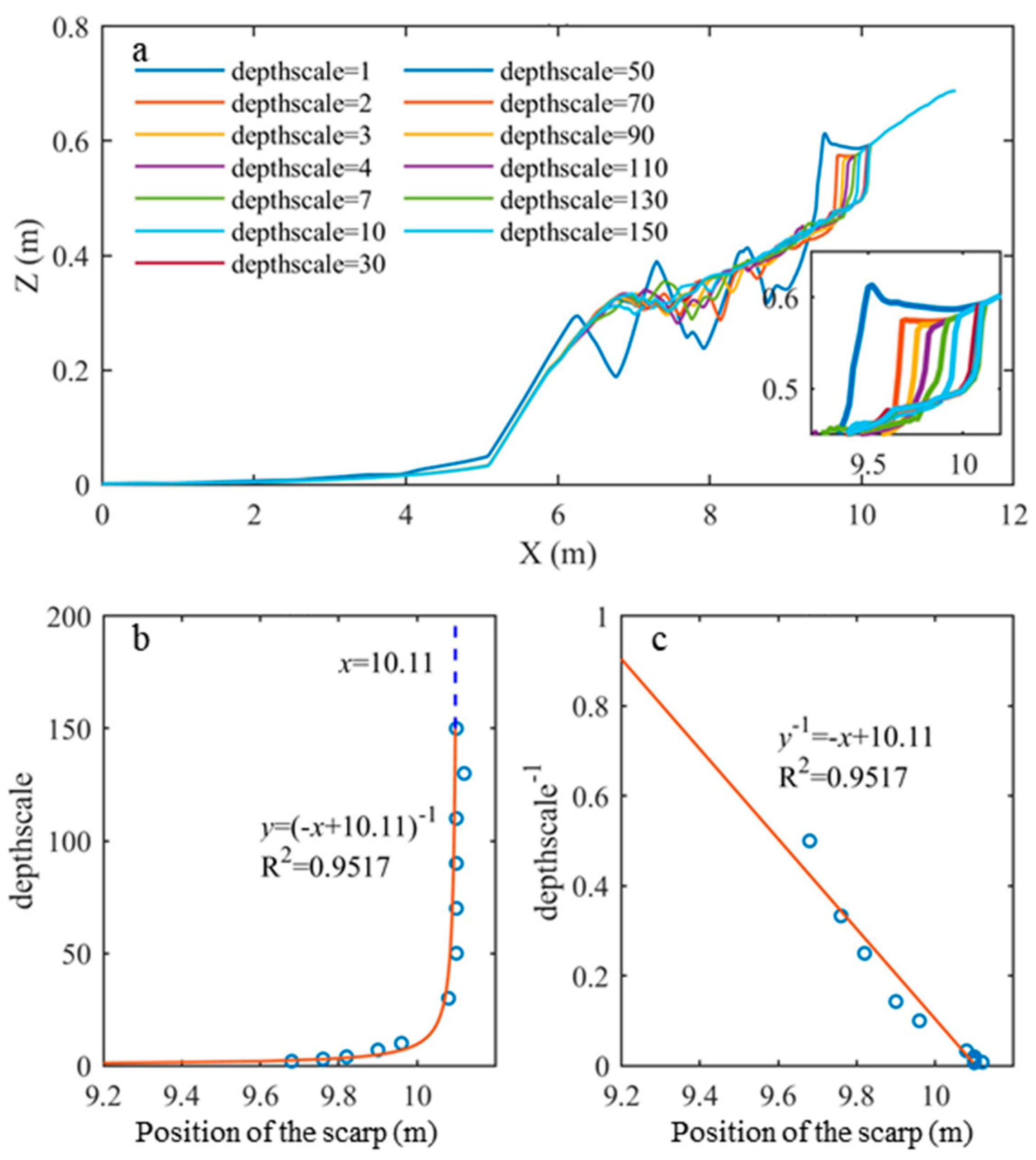
The water depth factor (depthscale) consists of eps (threshold water depth above which cells are considered wet), hmin (threshold water depth above which Stokes drift is included), hswitch (water depth at which is switched from critical avalanching slope under water to critical avalanching slope above water) and dzmax (maximum bed level change due to avalanching). Figure 11 shows the final morphology and position of scarp by different values of depthscale in non-hydrostatic simulation. The default value of depthscale is 1, and the suggested range is between 1 and 200. Then thirteen values of depthscale are set for sensitivity analysis by 1, 2, 3, 4, 7, 10, 30, 50, 70, 90, 110, 130 and 150. Figure 11 illustrates that with the increase of depthscale, the scarp moves onshore. Meanwhile, the sandbar is formed but the trough varies irregularly. According to the fittings by least square method, a relationship is established between the position of scarp (y) and depthscale (x):
y 1 = x + 10.11
With the limits of water level and uprush height, the scarp no longer moves onshore for increasing depthscale at the position (x = 10.11 m).
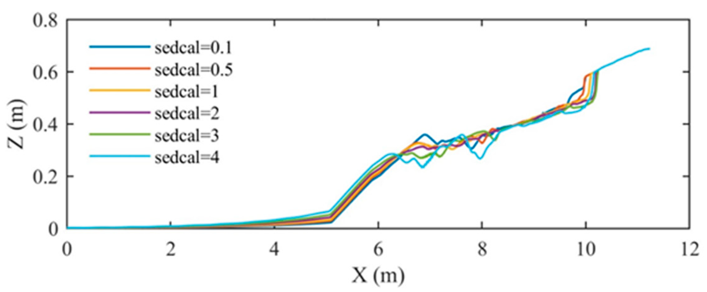
Equilibrium sediment concentration factor (sedcal) represents an equilibrium state of sediment erosion and deposition. If sedcal is high, more sediments would be suspended to compensate for the gap of practical sediment concentration. Figure 12 shows the final morphology by different values of sedcal in non-hydrostatic simulation. Six values of sedcal are set for sensitivity analysis by 0.1, 0.5, 1, 2, 3, 4, respectively. As shown in Figure 12, increasing sedcal extends the erosion area, where the sandbar moves offshore and the scarp moves onshore. However, the sandbar is formed irregularly in terms of the shape. Such results demonstrate that the beach profile evolution is more sensitive to depthscale.

5. Conclusions

To investigate the impacts of artificial reefs on beach profile evolution, a non-hydrostatic model based on XBeach is established. Same as the previous experiment by Ma et al. [38], the beach with and without the artificial reef are examined. Hydrodynamic and morphodynamic responses to the artificial reef are focused on regular wave conditions. In addition, effects of the artificial reef under irregular wave conditions are compared with those of regular wave conditions. Sensitivity analysis is conducted regarding three key model parameters in non-hydrostatic simulation, i.e., maximum wave steepness criterium (maxbrsteep), water depth factor (depthscale), and equilibrium sediment concentration factor (sedcal):
The conclusions are as follows:
  • The artificial reef causes wave reflection and wave breaking further offshore, therefore, effectively attenuate waves;
  • The intensive offshore flow plays a dominant role in suspended load transport, and the artificial reef decelerates local flow and reduces the offshore sediment transport by 51%;
  • Regular waves transform the initial plane beach into a sandbar-trough-scarp profile, where the artificial reef reduces the total erosion amount per unit width by 53%;
  • Over the artificial reef, wave skewness and asymmetry undergo a drastic change;
  • Under irregular wave conditions, short waves contribute to the wave energy mainly. Meanwhile, standing wave effects due to wave reflection by the artificial reef decline considerably;
  • Irregular waves transform the initial plane beach to a terrace-scarp profile, where the artificial reef shows good performances in protecting beach from excessive erosions under both regular and irregular wave conditions;
  • In wave breaking area, the increase of maximum wave steepness criterium (maxbrsteep) may increase the wave height. With increasing water depth factor (depthscale), the scarp extends onshore until x = 10.11 m due to the limit of water level and uprush height. Increasing equilibrium sediment concentration factor (sedcal) extends the erosion area, but form the sandbar irregularly varying irregularly in shape.
Based on the non-hydrostatic simulation, the protecting effects of artificial reefs have been investigated alone. Additional protection measures should be considered for the coast which still suffers from erosions after beach nourishment. Moreover, climate changes, such as sea level rise and recurrent wind storms, have been threatening sandy beaches around the world, which leads to shoreline recessions considerably [55,56,57,58]. The non-hydrostatic model can be applied for the reliable simulation of beach responses to sea level rise and storm surges [59,60]. Furthermore, erosion hotspots indicate the erosive characteristics of sandy beaches predominately [61,62], so it is feasible to use the non-hydrostatic model to identify erosion hotspots during the beach profile evolution. The numerical results may help optimize local restoration effort to mitigate erosion at the hotspots. To overcome the model sensitivities to the maximum wave steepness criterium (maxbrsteep), one- and two- phase Reynolds Averaged Navier–Stokes solver (RANS) and Volume of Fluid (VOF) surface capturing scheme (RANS-VOF) may be used to directly resolve the breaking point and the overturning breaking wave surface profile and the resulting turbulence and morphological changes with and without an artificial reef [48,50,63,64]. With the further optimization of the non-hydrostatic model, a wider range of wave conditions and arrangements of multiple artificial constructions will be taken into accounts for further investigations in near future.

Author Contributions

Conceptualization, C.K. and J.F.; methodology, X.H.; software, H.L.; validation, C.K., J.F. and X.H.; formal analysis, H.L.; investigation, J.F.; resources, R.Q.; data curation, H.L.; writing—original draft preparation, C.K. and X.H.; writing—review and editing, J.F. and Q.Z.; supervision, R.Q. and Q.Z.; project administration, C.K.; funding acquisition, C.K. All authors have read and agreed to the published version of the manuscript.

Funding

This research was funded by the National Key Research and Development Project of China (Grant No. 2022YFC3106205) and the National Natural Science Foundation of China (Grant Nos. 41976159 and 41776098). Professor Qingping Zou has been supported by the Natural Environment Research Council of UK (Grant No. NE/V006088/1) and Scottish Government (CRW2022_02).

Data Availability Statement

The data presented in this study are available on request from the corresponding author. The data are not publicly available due to reasons related to national security.

Conflicts of Interest

The funders had no role in the design of the study, in the collection, analysis, or interpretation of data, in the writing of the manuscript, or in the decision to publish the results.

References

  1. Vallam, S.; Annamalaisamy, S.S.; Ramesh, S.B. Sustainable hard and soft measures for coastal protection—Case studies along the Indian Coast. Mar. Georesour. Geotechnol. 2022, 40, 600–615. [Google Scholar]
  2. Ryzhakov, P.; Hermosilla, F.; Ubach, P.-A.; Oñate, E. Adaptive breakwaters with inflatable elements for coastal protection. Preliminary numerical estimation of their performance. Ocean Eng. 2022, 251, 110818. [Google Scholar] [CrossRef]
  3. Celli, D.; Li, Y.; Ong, C.M.; Di Risio, M. The role of submerged berms on the momentary liquefaction around conventional rubble mound breakwaters. Appl. Ocean Res. 2019, 85, 1–11. [Google Scholar]
  4. Semeoshenkova, V.; Newton, A. Overview of erosion and beach quality issues in three Southern European countries: Portugal, Spain and Italy. Ocean Coast. Manag. 2015, 118, 12–21. [Google Scholar] [CrossRef]
  5. Cantasano, N.; Boccalaro, F.; Ietto, F. Assessing of detached breakwaters and beach nourishment environmental impacts in Italy: A review. Environ. Monit. Assess. 2022, 195, 127. [Google Scholar] [CrossRef]
  6. Ma, Z.; Melville, D.S.; Liu, J.; Chen, Y.; Yang, H.; Ren, W.; Zhang, Z.; Piersma, T.; Li, B. Rethinking China’s new great wall. Science 2014, 346, 912–914. [Google Scholar] [CrossRef]
  7. Qi, H.S.; Liu, G.; Cai, F.; Zhu, J.; Liu, J.H.; Lei, G.; He, Y.Y.; Zheng, J.X.; Cao, H.M. Development trend and prospect of beach nourishment technology. J. Appl. Oceanogr. 2021, 40, 111–125. [Google Scholar]
  8. Schoonees, T.; Mancheño, G.A.; Scheres, B.; Bouma, T.J.; Silva, R.; Schlurmann, T.; Schüttrumpf, H. Hard structures for coastal protection, towards greener designs. Estuaries Coasts 2019, 42, 1709–1729. [Google Scholar]
  9. Elko, N.; Briggs, T.R.; Benedet, L.; Robertson, Q.; Thomson, G.; Webb, B.M.; Garvey, K. A century of U.S. beach nourishment. Ocean Coast. Manag. 2021, 199, 105406. [Google Scholar] [CrossRef]
  10. de Vriend, H.J.; van Koningsveld, M.; Aarninkhof, S.G.J.; de Vries, M.B.; Baptist, M.J. Sustainable hydraulic engineering through building with nature. J. Hydro-Environ. Res. 2015, 9, 159–171. [Google Scholar] [CrossRef]
  11. Dornhelm, R.B. The Coney Island public beach and boardwalk improvement of 1923. In Urban Beaches: Balancing Public Rights and Private Development; ASCE: Preston, VA, USA, 2003; pp. 52–63. [Google Scholar]
  12. Roest, B.; de Vries, S.; de Schipper, M.; Aarninkhof, S. Observed changes of a mega feeder nourishment in a coastal cell: Five years of Sand Engine morphodynamics. J. Mar. Sci. Eng. 2021, 9, 37. [Google Scholar]
  13. Aleixo, C.P.; Mendes, T.S.; Braz, S.T. Beach nourishment practice in mainland Portugal (1950–2017): Overview and retrospective. Ocean Coastal Manag. 2020, 192, 105211. [Google Scholar]
  14. Hamm, L.; Capobianco, M.; Dette, H.H.; Lechugad, A.; Spanhoffe, R.; Stive, M.J.F. A summary of European experience with shore nourishment. Coast. Eng. 2002, 47, 237–264. [Google Scholar]
  15. Bitan, M.; Zviely, D. Sand Beach Nourishment: Experience from the Mediterranean Coast of Israel. J. Mar. Sci. Eng. 2020, 8, 273. [Google Scholar] [CrossRef]
  16. Ali, A.; Abdullah, M.R.; Safuan, C.D.M.; Afiq-Firdaus, A.M.; Bachok, Z.; Akhir, M.F.M.; Latif, R.; Muhamad, A.; Seng, T.H.; Roslee, A.; et al. Side-scan sonar coupled with scuba diving observation for enhanced monitoring of benthic artificial reefs along the coast of Terengganu, Peninsular Malaysia. J. Mar. Sci. Eng. 2022, 10, 1309. [Google Scholar]
  17. David da Costa, I.; Luís da Silva, S.J.; Costa, L.L.; Lima, J.S.; Zalmon, I.R. Reproductive potential and production role of artificial reefs—Southeastern Brazil. Estuar. Coast. Shelf Sci. 2022, 265, 107710. [Google Scholar]
  18. Wang, G.; Wan, R.; Wang, X.X.; Zhao, F.F.; Lan, X.Z.; Cheng, H.; Tang, W.Y.; Guan, Q.L. Study on the influence of cut-opening ratio, cut-opening shape, and cut-opening number on the flow field of a cubic artificial reef. Ocean Eng. 2018, 162, 341–352. [Google Scholar]
  19. Nie, Z.; Zhu, L.; Xie, W.; Zhang, J.; Wang, J.; Jiang, Z.; Liang, Z. Research on the influence of cut-opening factors on flow field effect of artificial reef. Ocean Eng. 2022, 249, 110890. [Google Scholar] [CrossRef]
  20. Tang, Y.; Yang, W.; Sun, L.; Zhao, F.; Long, X.; Wang, G. Studies on factors influencing hydrodynamic characteristics of plates used in artificial reefs. J. Ocean Univ. China 2019, 18, 193–202. [Google Scholar]
  21. Zheng, Y.; Kuang, C.; Zhang, J.; Gu, J.; Chen, K.; Liu, X. Current and turbulence characteristics of perforated box-type artificial reefs in a constant water depth. Ocean Eng. 2022, 244, 110359. [Google Scholar]
  22. Maslov, D.; Pereira, E.; Duarte, D.; Miranda, T.; Ferreira, V.; Tieppo, M.; Cruz, F.; Johnson, J. Numerical analysis of the flow field and cross section design implications in a multifunctional artificial reef. Ocean Eng. 2023, 272, 113817. [Google Scholar]
  23. Zhang, J.; Zhu, L.; Liang, Z.; Sun, L.; Nie, Z.; Wang, J.; Xie, W.; Jiang, Z. Numerical study of efficiency indices to evaluate the effect of layout mode of artificial reef unit on flow field. J. Mar. Sci. Eng. 2021, 9, 770. [Google Scholar]
  24. Xue, D.; Wang, C.; Huang, T.; Pan, Y.; Zhang, N.; Zhang, L. Flow field effects and physical stability of pyramidal artificial reef with different slope angles. Ocean Eng. 2023, 283, 115059. [Google Scholar]
  25. Zhou, P.; Gao, Y.; Zheng, S. Three-dimensional numerical simulation on flow behavior behind trapezoidal artificial reefs. Ocean Eng. 2022, 266, 112899. [Google Scholar]
  26. Jung, S.; Na, W.-B.; Kim, D. Rugosity and blocking indices of artificial reefs and their correlations with wake volume. Ocean Eng. 2022, 261, 112204. [Google Scholar]
  27. Shu, A.; Wang, M.; Qin, J.; Wang, S.; Zhu, F. The characteristics for flow field distribution and sediment incipient movement around the typical artificial reefs area in Bohai Bay. SHUILI XUEBAO 2020, 51, 1223–1233. [Google Scholar]
  28. Shu, A.; Qin, J.; Sun, T.; Yang, W.; Wang, M.; Zhu, J. Discussion on water and sediment dynamic characteristics and layout optimization of typical artificial reefs in Liaodong Bay of Bohai Sea. SHUILI XUEBAO 2022, 53, 43–53. [Google Scholar]
  29. Zhang, Q. Effects of Different Structures on Flow Resistance and Experiment on Local Scour of Artificial Reef. Master’s Thesis, Shanghai Ocean University, Shanghai, China, 13 May 2022. [Google Scholar]
  30. Tang, Y.; Wei, S.; Yang, M.; Wang, X.; Zhao, F. Experimental investigation of local scour around artificial reefs in steady currents. J. Ocean Univ. China 2022, 21, 445–456. [Google Scholar]
  31. Luijendijk, A.; Hagenaars, G.; Ranasinghe, R.; Baart, F.; Donchyts, G.; Aarninkhof, S. The state of the world’s beaches. Sci. Rep. 2018, 8, 6641. [Google Scholar]
  32. Eelsalu, M.; Parnell, K.E.; Soomere, T. Sandy beach evolution in the low-energy microtidal Baltic Sea: Attribution of changes to hydrometerological forcing. Geomorphology 2022, 414, 108383. [Google Scholar]
  33. Wu, X. Numerical Modelling of Sediment Transport in an Artificial Reef Area. Ph.D. Thesis, Shanghai Ocean University, Shanghai, China, 20 May 2019. [Google Scholar]
  34. Vieira da Silva, G.; Hamilton, D.; Strauss, D.; Murray, T.; Tomlinson, R. Sediment pathways and morphodynamic response to a multi-purpose artificial reef—New insights. Coast. Eng. 2022, 171, 104027. [Google Scholar] [CrossRef]
  35. Schuh, E.; Grilli, A.R.; Groetsch, F.; Grilli, S.T.; Crowley, D.; Ginis, I.; Stempel, P. Assessing the morphodynamic response of a New England beach-barrier system to an artificial reef. Coast. Eng. 2023, 184, 104355. [Google Scholar]
  36. Yang, L.P.; Yang, S.P.; Zhang, Z.Y.; Zhu, J.L.; Shi, B. Experimental study on wave dissipation and beach protection by gravel dam and porous square reef: Taking Beidaihe West Beach as the example. Coastal Eng. 2022, 41, 223–232. [Google Scholar]
  37. Kuang, C.; Ma, Y.; Han, X.; Pan, S.; Zhu, L. Experimental observation on beach evolution process with presence of artificial submerged sand bar and reef. J. Mar. Sci. Eng. 2020, 8, 1019. [Google Scholar] [CrossRef]
  38. Ma, Y.; Kuang, C.; Han, X.; Niu, H.; Zheng, Y.; Shen, C. Experimental study on the influence of an artificial reef on cross-shore morphodynamic processes of a wave-dominated beach. Water 2020, 12, 2947. [Google Scholar] [CrossRef]
  39. Gharagozlou, A.; Dietrich, J.C.; Karanci, A.; Luettich, R.A.; Overton, M.F. Storm-driven erosion and inundation of barrier islands from dune to region-scales. Coast. Eng. 2020, 158, 103674. [Google Scholar] [CrossRef]
  40. Roelvink, D.; McCall, R.; Mehvar, S.; Nederhoff, K.; Dastgheib, A. Improving predictions of swash dynamics in Xbeach: The role of groupiness and incident-band runup. Coast. Eng. 2018, 134, 103–123. [Google Scholar] [CrossRef]
  41. Roelvink, D.; Reniers, A.; van Dongeren, A.; de Vries, J.V.T.; McCall, R.; Lescinski, J. Modelling storm impacts on beaches, dunes and barrier islands. Coast. Eng. 2009, 56, 1133–1152. [Google Scholar] [CrossRef]
  42. Cui, H.; Pietrzak, J.D.; Stelling, G.S. Optimal dispersion with minimized Poisson equations for non-hydrostatic free surface flows. Ocean Model. 2014, 81, 1–12. [Google Scholar]
  43. de Ridder, M.P.; Smit, P.B.; van Dongeren, A.; McCall, R.; Nederhoff, K.; Reniers, A.J.H.M. Efficient two-layer non-hydrostatic wave model with accurate dispersive behaviour. Coast. Eng. 2021, 164, 103808. [Google Scholar] [CrossRef]
  44. Zijlema, M.; Stelling, G.; Smit, P. SWASH: An operational public domain code for simulating wave fields and rapidly varied flows in coastal waters. Coast. Eng. 2011, 58, 992–1012. [Google Scholar] [CrossRef]
  45. Stelling, G.; Zijlema, M. An accurate and efficient finite-difference algorithm for non-hydrostatic free-surface flow with applica-tion to wave propagation. Int. J. Numer. Methods Fluids 2003, 43, 1–23. [Google Scholar] [CrossRef]
  46. Lam, D.C.L.; Simpson, R.B. Centered differencing and the box scheme for diffusion convection problems. J. Comput. Phys. 1976, 22, 486–500. [Google Scholar] [CrossRef]
  47. Willmott, C.J. On the validation of models. Phys. Geogr. 1981, 2, 184–194. [Google Scholar] [CrossRef]
  48. Zou, Q.; Peng, Z. Evolution of wave shape over a low-crested structure. Coastal Eng. 2011, 58, 478–488. [Google Scholar] [CrossRef]
  49. Peng, Z.; Zou, Q.; Reeve, D.E.; Wang, B. Parameterisation and transformation of wave asymmetries over a low-crested breakwater. Coastal Eng. 2009, 56, 1123–1132. [Google Scholar] [CrossRef]
  50. Peng, Z.; Zou, Q.; Lin, P. A partial cell technique for modeling the morphological change and scour. Coastal Eng. 2018, 131, 88–105. [Google Scholar] [CrossRef]
  51. Ruessink, B.V.; Van Den Berg, T.J.J.; Van Rijn, L.C. Modeling sediment transport beneath skewed asymmetric waves above a plane bed. J. Geophys. Res. Oceans 2009, 114, 1–14. [Google Scholar] [CrossRef]
  52. Gonzalez-Rodriguez, D.; Madsen, O.S. Seabed shear stress and bedload transport due to asymmetric and skewed waves. Coastal Eng. 2007, 54, 914–929. [Google Scholar] [CrossRef]
  53. Hoefel, F.; Elgar, S. Wave-induced sediment transport and sandbar migration. Science 2003, 299, 1885–1887. [Google Scholar] [CrossRef]
  54. Goda, Y.; Suzuki, Y. Estimation of incident and reflected waves in random wave experiments. Coastal Eng. 1976, 1976, 828–845. [Google Scholar] [CrossRef]
  55. Dastgheib, A.; Martinez, C.; Udo, K.; Ranasinghe, R. Climate change driven shoreline change at Hasaki Beach Japan: A novel application of the Probabilistic Coastline Recession (PCR) model. Coast. Eng. 2021, 172, 104079. [Google Scholar] [CrossRef]
  56. Bonaldo, D.; Bucchignani, E.; Pomaro, A.; Ricchi, A.; Sclavo, M.; Carniel, S. Wind waves in the Adriatic Sea under a severe climate change scenario and implications for the coasts. Int. J. Clim. 2020, 40, 5389–5406. [Google Scholar] [CrossRef]
  57. Forgiarini, A.P.P.; de Figueiredo, S.A.; Calliari, L.J.; Goulart, E.S.; Marques, W.; Trombetta, T.B.; Oleinik, P.H.; Guimaraes, R.C.; Arigony-Neto, J.; Salame, C.C. Quantifying the geomorphologic and urbanization influence on coastal retreat under sea level rise. Estuar. Coast. Shelf Sci. 2019, 230, 106437. [Google Scholar] [CrossRef]
  58. Thepsiriamnuay, H.; Pumijumnong, N. Modelling Assessment of Sandy Beaches Erosion in Thailand. Environ. Nat. Resour. J. 2018, 17, 71–86. [Google Scholar] [CrossRef]
  59. Vousdoukas, M.I.; Ranasinghe, R.; Mentaschi, L.; Plomaritis, T.A.; Athanasiou, P.; Luijendijk, A.; Feyen, L. Sandy coastlines under threat of erosion. Nat. Clim. Chang. 2020, 10, 260–263. [Google Scholar] [CrossRef]
  60. Bagheri, M.; Zaiton Ibrahim, Z.; Bin Mansor, S.; Abd Manaf, L.; Badarulzaman, N.; Vaghefi, N. Shoreline change analysis and erosion prediction using historical data of Kuala Terengganu, Malaysia. Environ. Earth Sci. 2019, 78, 1–21. [Google Scholar] [CrossRef]
  61. Frohlich, M.F.; Smith, T.F.; Fidelman, P.; Baldwin, C.; Jacobson, C.; Carter, R.B. Legal barriers to adaptive coastal management at a coastal erosion hotspot in Florianópolis, Brazil. Mar. Policy 2021, 127, 104436. [Google Scholar] [CrossRef]
  62. Yu, J.; Ding, Y.; Zhang, L.; Liu, P.; Fan, R. Erosion hotspot identified along the sandy coast of Shanwei: Characteristics and origin. Acta Oceanol. Sin. 2023, 42, 91–102. [Google Scholar] [CrossRef]
  63. Bakhtyar, R.; Razmi, A.M.; Barry, D.A.; Yeganeh-Bakhtiary, A.; Zou, Q. Air-water two-phase flow modeling of turbulent surf and swash zone wave motions. Adv. Water Resour. 2010, 33, 1560–1574. [Google Scholar] [CrossRef]
  64. Lara, J.L.; Garcia, N.; Losada, I.J. RANS modelling applied to random wave interaction with submerged permeable structures. Coastal Eng. 2006, 53, 395–417. [Google Scholar] [CrossRef]
Figure 1. Experiment set-up for the beach (a) without and (b) with an artificial reef [38].
Water 15 03832 g001
Figure 2. Validations of the predicted wave surface profile time series by non-hydrostatic model XBeach against the experiment [38].
Water 15 03832 g002
Figure 3. Validation of predicted beach profile by non-hydrostatic model against the experiment by Ma et al. [38].
Water 15 03832 g003
Figure 4. Predicted wave surface profile and beach profile at 60 s for the beach (a) without and (b) with the artificial reef.
Water 15 03832 g004
Figure 5. Predicted cross-shore profile of wave skewness and asymmetry for the beach (a) without and (b) with the artificial reef.
Water 15 03832 g005
Figure 6. Time average velocity, upper and lower velocity and their difference for the beach (a) without and (b) with the artificial reef.
Water 15 03832 g006
Figure 7. Suspended load and bedload transport rate for the beach (a) without and (b) with the artificial reef.
Water 15 03832 g007
Figure 8. Initial and final morphology and their difference for the beach (a) without and (b) with the artificial reef.
Water 15 03832 g008
Figure 9. (a) Total significant wave height, significant wave height of short waves and long waves; (b) wave skewness and asymmetry; (c) time average velocity, upper and lower velocity and their difference; (d) suspended load and bedload transport rate; (e) initial and final morphology and their difference for the beach with the artificial reef under irregular waves.
Water 15 03832 g009
Figure 10. Wave surface profile time series at wave gauge (a) W1 the wave breaking area and (b) W9 in the offshore area by the non-hydrostatic simulation using different values of maximum wave steepness criterium, maxbrsteep.
Water 15 03832 g010
Figure 11. (a) Final morphology; (b) position of the scarp; (c) position of the scarp by non-hydrostatic simulation using different values of water depth factor (depthscale).
Water 15 03832 g011
Figure 12. Final morphology by non-hydrostatic simulation using different values of equilibrium sediment concentration factor (sedcal).
Water 15 03832 g012
Table 1. Model-data comparisons.
ItemPositiondEvaluation
Wave surfaceW10.9421Excellent
Wave surfaceW20.9917Excellent
Wave surfaceW30.9925Excellent
Wave surfaceW40.9936Excellent
Wave surfaceW50.9905Excellent
Wave surfaceW60.9942Excellent
Wave surfaceW70.9921Excellent
Wave surfaceW80.9966Excellent
Wave surfaceW90.9955Excellent
Beach profile 0.9953Excellent
Disclaimer/Publisher’s Note: The statements, opinions and data contained in all publications are solely those of the individual author(s) and contributor(s) and not of MDPI and/or the editor(s). MDPI and/or the editor(s) disclaim responsibility for any injury to people or property resulting from any ideas, methods, instructions or products referred to in the content.