Article

Numerical Study of Fluid–Solid Interaction in Elastic Sluice Based on SPH Method

College of Water Conservancy, North China University of Water Resources and Hydropower, Zhengzhou 450046, China
*
Author to whom correspondence should be addressed.
Water 2023, 15(21), 3738; https://doi.org/10.3390/w15213738
Submission received: 24 September 2023 / Revised: 20 October 2023 / Accepted: 20 October 2023 / Published: 26 October 2023
(This article belongs to the Special Issue Feature Papers of Hydraulics and Hydrodynamics)

Abstract

:
In this paper, the fluid–solid interaction problem involving structural movement and deformation is considered, and an SPH (smoothed particle hydrodynamics) interaction method is proposed to establish a numerical fluid–solid model and to correct the particle velocities in the momentum conservation equations. It is found that, when the smoothing coefficient is equal to 0.93, the similarity of the free surface curves reaches up to 91.9%, and calculations are more accurate. Under the same working conditions, the classical model of elastic sluice discharge is established based on the SPH method and the finite element method, and the validity and accuracy of the model based on the SPH method are verified by analyzing the flow pattern of the sluice discharge, the opening of the elastic gate, and the change trend in the free liquid surface curve. On this basis, a number of characteristic points on the sluice gate are selected based on the SPH model to investigate the change rule of pressure at the fluid–solid interface, and the results are as follows: (1) based on the numerical model established by the SPH method, the flow pattern of the water, the opening of the elastic gate, and the change in the free liquid level curve are all in better agreement with the experimental results in the literature than those of the finite element method, and the computational results are also better; (2) the pressure of the solid on the fluid at each characteristic point is equal to the pressure of the fluid on the solid, which satisfies the principle of action–reaction and laterally verifies the nature of the dynamic boundary between the fluid and the solid, further verifying the validity of the program; and (3) in the process of sluice discharge, the elastic sluice presents a large force at both ends and a small force in the middle, meaning that the related research in this paper can act as a reference for flow–solid interaction problems related to sluice discharge.

1. Introduction

Fluid–structure interactions (FSIs) are a mechanical problem in which a fluid and a structure interact and depend on each other [1]. Coupled fluid–solid interactions are widely used in many engineering fields such as hydraulic engineering, mechanical engineering, ocean engineering, and aerospace engineering [2,3,4,5,6,7,8,9,10]. With the advancement and development of numerical computing, a variety of fluid–solid computational methods, such as the finite difference method (FDM) and finite element method (FEM), have been widely used in the study of computational fluid dynamics (CFD) and computational solid mechanics (CSM) [11]. However, the computation of both the FDM and FEM methods is based on an Eulerian mesh, which makes it extremely difficult to accurately determine free surfaces, track deformation boundaries, and multiply positional transformations between inhomogeneous substances. Aiming at the drawbacks of the Eulerian method, pure Lagrangian, Eulerian–Lagrangian (CEL), Lagrangian–Eulerian (ALE), and other methods have been used for calculation since they make tracking the fluid–solid interface simple, without the need for complex mesh regeneration and conversion, and greatly increase the computational efficiency. Therefore, the Lagrangian method, CEL, ALE, etc., are ideal methods for solving FSI problems involving a large deformation of fluids and complex solid boundaries [12,13].
For the modeling of fluid–solid interaction (FSI) problems, a combination of ALE and CEL methods is usually used, where the ALE method employs both Lagrangian and Eulerian methods in different regions of the problem domain, generally discretizing the fluid in the Lagrangian coordinate system and discretizing the solid in the Eulerian coordinate system. The CEL method, on the other hand, discretizes solids in the Lagrangian coordinate system and fluids in the Eulerian coordinate system. Zhang et al. [14] proposed the SPHS-BEM (Symmetric Positive Definite-Based Element Mesh) interaction method to solve the transient fluid–solid interaction problem, which identifies the interaction conditions between the coupled surface and the MLS (moving least squares) method and improves the accuracy and stability of the numerical model. Wu et al. [15] studied and proposed a two-dimensional SPH-DEM (smoothed particle hydrodynamics–discrete element method) fluid–structure interaction model to solve the problems related to large deformation and fracturing of the structure in FSI problems. Raymond et al. [16] proposed a numerical simulation method combining the material particle method MPM (Mixed and Partial Method) and SPH, which solves the problems related to the change in resolution in the large deformation region that occurs due to FSI. Liu [17] proposed the FSI numerical method that combines SPH with the finite particle method (FPM) to solve the problems of fluid–solid modeling such as solid contact, damage, and nonlinear deformation, improve the contact force based on the Displayed Contact Algorithm DENA (Differential Evolution with Noise), and optimize the neighboring particle search method. Yao Xuehao et al. [18] proposed the interaction method of virtual and repulsive particles PD-SPH (Particle-Driven SPH) to solve the FSI problem, which accounted for the phenomenon of mutual penetration between particles and corrected the boundary defects of the particles using virtual particles. He Tao et al. [19] proposed a partitioned strong interaction method using the Lagrangian–Eulerian (ALE) finite element technique for different FSI problems, and solved the related control equations by using a semi-implicit CBS (semi-implicit Conjugate Gradient Squared) algorithm, where the results revealed typical flow-induced vibration phenomena. Boscheri et al. [20] proposed a new series of higher-order exact arbitrary Lagrangian–Eulerian (ALE) one-step ADER-WENO finite-volume schemes for solving nonlinear systems of conservative and nonconservative hyperbolic partial differential equations with rigid source terms on three-dimensional moving tetrahedral meshes. Although the CEL and ALE algorithms have been developed very rapidly and are widely used for large deformation and FSI problems, the generation of meshes is still highly distorted when modeling with CEL and ALE, and serious errors can occur, leading to inaccurate calculation results.
Currently, most of the existing fluid solvers and solid solvers are based on grid methods where the grid is predefined. There are special difficulties with traditional grids, and these difficulties limit their application and development in FSI problems. When solving solid problems in the Lagrangian coordinate system, such as with the FEM method, the motion and deformation of the object under the impact of the water flow is dependent on the mesh. Due to the mesh deformation problem, it is extremely difficult for the FEM to deal with large deformation problems. In addition, mesh division is necessary in the FEM, and when dealing with mesh problems it often requires a large amount of time to produce a solution and reduce the efficiency of the calculation, which may even lead to inaccurate calculation results [21,22]. In the past few decades, with the advancement of various numerical simulation methods, numerical research methods using computer technology have developed rapidly [23,24,25]. In order to make the FSI calculation results more accurate, people are committed to developing the next generation of calculation methods, i.e., meshless methods. For example, the SPH method has been adopted to discretize the fluid domain and solid domain in a pure Lagrangian coordinate system, and the model has the advantage of easily defining the fluid–solid interface; even if there is a large structural displacement, it does not require any special treatment of the free surface or the fluid [26,27]. Therefore, the fluid–solid coupling model using the SPH method can greatly improve the computational accuracy and computational efficiency on the basis of dealing with problems such as high-speed impact and large deformation.
The above studies show that there are relatively few studies using the SPH method that can establish a numerical model of fluid–solid interactions. This paper establishes a classical model of sluice discharge with the ability to simulate a strong FSI problem based on the SPH method, and corrects the particle velocity in the momentum equation to improve the computational accuracy and stability. Based on this, by analyzing the change in the flow pattern of the water, the change trend of the gate, the evolution of the free liquid level and the related experiments in the literature, and the numerical model based on the finite element method under equal working conditions, as well as analyzing the change in the dynamic boundary force between the flow and solid of the SPH method, we can further validate the accuracy and superiority of the SPH program.

2. Numerical Model

2.1. Governing Equations

Under isothermal conditions, there is no need to consider the law of conservation of energy, so the motion of fluids and solids under gravity can be described by the equations of the conservation of mass and conservation of momentum [28,29].
The mass conservation equation is
d ρ dt + ρ ν i χ i = 0
The equation for conservation of momentum is
ρ d ν i d t = ρ g i + σ ij χ j
where t is the time; ν is the velocity; ρ is the density; χ is the position; g is gravity; and σ ij is the stress tensor.
The stress tensor can be decomposed into its isotropic and deviatoric parts:
σ ij = P δ ij + S ij
Of these,
P = C 0 2 ( ρ ρ 0 )
where P is the pressure; δ ij is the Kronecker tensor; and S ij is the bias stress tensor. For fluids, C 0 = ε ρ 0 ; for solids, C 0 = k ρ 0 . ε is the compressible modulus of the fluid and k is the bulk modulus of the solid.
For fluids, the viscosity effect is negligible if the fluid motion is dominated by inertial forces; that is, assuming that this is true for the fluid, the linear elastic relationship between the stress and deformation tensor for solids can be derived accurately and in a timely manner. This leads to the evolution equation of S ij , which uses the rotation time derivative, also known as the Jaumann time derivative, as detailed in [30,31,32]. This formulation is a solid (elastic) eigenstructure model proposed in the context of SPH, which relates the stress velocity to the deformation rate, but its disadvantage is that the law of energy conservation is not satisfied in the case of large deformations; so, in this paper, we study the case of a fluid–solid interaction in an isothermal state, and there is no need to consider the conservation of energy. The advantage of this is that it is possible to discretize the fluid and the solid at the same time in terms of both pressure and velocity [33].
d S ij dt = 2 μ d ij 1 3 δ ij d ij + S ik Ω jk + S kj Ω ik
Among them,
d ij = 1 2 ν i χ j + ν j χ i
Ω ij = 1 2 ν i χ j ν j χ i
where d ij is the deformation rate tensor; Ω ij is the rotation tensor; μ is the shear modulus; g is gravity; and σ ij is the stress tensor.

2.2. SPH Methodology

The SPH method is a purely Lagrangian meshless method, and in this paper, both fluids and solids are described by SPH particles, all of which move according to the laws of the governing equations. In the SPH method, the kernel approximation and particle approximation are performed based on the selection of suitable kernel functions according to Monaghan [34]. The density and velocity of the particles are constantly updated by solving the equations of the conservation of mass and conservation of momentum, where the derivative of the velocity can be obtained by the calculation of the momentum equation, and then integration is performed to calculate the trajectory of the particles.
According to the mass conservation equation (continuity equation), the derivative of the density of particle a (fluid or solid) can be expressed by SPH interpolation as
d ρ a dt = b m b ν a ν b a W ab
where m is the mass of the particle; W is the smooth kernel function; and ν a ν b is the difference in velocity between particles a and b.
The smooth kernel function adopts the quintic spline function, and in order to verify its smoothness, the first- and second-order derivative function images of this function are plotted, as shown in Figure 1.
W R , h = α d × 3 R 5 6 2 R 5 + 15 1 R 5 0 R 1 3 R 5 6 2 R 5 1 R < 2 3 R 5 2 R < 3 0 R 3
where α d , taken in one, two, and three dimensions, is 1 120 h , 7 478 π h 2 , 3 359 π h 3 , respectively, and h is the smooth length. R = x h , where x is the distance between the two particles.
According to the momentum conservation equation, the SPH format approximation of the fluid particle a can be expressed as follows, without considering the viscous stress:
d ν i a dt = b m b ( p a ρ a 2 + p b ρ b 2 ) δ i j W ab a χ j + g i
The SPH format approximation for solid particle a can be expressed as
d ν i a dt = b m b ( p a ρ a 2 + p b ρ b 2 ) δ i j + S ij a ρ a 2 + S ij b ρ b 2 + Π ab δ ij + R ij ab f q W ab a χ j + g i
Equation (11) introduces an artificial viscosity term Π ab . Its purpose is to prevent the SPH algorithm from generating unphysical oscillations as it proceeds, and also to effectively prevent particles from penetrating each other as they approach.
Π ab α c ab μ ab ρ ab ν a ν b χ a χ b < 0 0 ν a ν b χ a χ b > 0
Among them,
c ab = 1 2 c a + c b
ρ ab = 1 2 ρ a + ρ b
μ ab = h ν a ν b χ a χ b χ a χ b 2 + 0.1 h 2
where c ab is the average of the sound velocities of particles a and b; ρ ab is the average of the densities of particles a and b; h is the smooth length from particle b to particle a; and α is the control parameter of the viscosity, which generally takes a value of about 1.0.
In Equation (11), the “artificial stress” term R ij ab f q is included. In the simulation of the tensile state of the solid, the SPH particles are extremely easy to gather together, thus causing an unphysical fracture, and the introduction of the “artificial stress” plays a very good role in repulsion, which is helpful to keep the volume of the fluid constant. The introduction of “artificial stresses” plays a good role in repulsion and helps to keep the volume of the fluid constant. When calculations involve the fluid flow, the results may be unstable for various reasons (e.g., uneven meshing or changes in fluid density). The introduction of an artificial stress term helps to adjust the stress distribution within the fluid, thus counteracting these instabilities to some extent and preventing particle aggregation [31].
R ij ab f q = R ij a + R ij b W χ a χ b W d q
Among them,
R ia = e σ ia ρ a 2
where q and e are conventional parameters; d is the initial distance between particles; and σ ij is the stress tensor. Gray et al. [35] derived the optimal solutions of 4 and 0.3.
The bias stress tensor S ij is obtained by time integrating the bias stress rate into this constitutive relation. The SPH approximation of the velocity gradient of particle a is required for the calculation of the spin and deformation rates, and the first-order Taylor expansion formula to determine the velocity of particle a is first introduced to obtain the following formula that identifies the components of its velocity gradient tensor:
b m b ρ b ν i b W ab a χ j = ν i a b m b ρ b W ab a χ j + ν i x k a b m b ρ b W ab a χ j χ k b χ k a
Equation (18) needs to be solved each time the velocity gradient is computed, and the computational efficiency will be reduced, but this formula takes into account the inhomogeneity of the particle distribution, so it is better than applying a direct SPH computational treatment to determine the velocity gradient.

2.3. Particle Velocity Correction

In order to make the particle velocity more reasonable and improve the accuracy and stability of the simulation, the particle velocity is corrected based on the magnitude and direction of the force applied to the particles. This article weights and corrects the particle velocity ν obtained with the time integration of the momentum conservation equation:
ν ˜ a = ν a + 1 λ b m b ρ ¯ ab ν b ν a W ab b m b ρ ¯ ab W ab
where ρ ¯ ab = 1 2 ρ a + ρ b is the average density of particles a and b; λ is the smoothing coefficient.
For solid particles, the corrected values are used in Equations (8) and (18) to constantly update the position of the particles according to the XSPH format proposed by Monaghan, while the uncorrected velocity particles are time-integrated using Equation (11); for fluids, the corrected velocities are also used in Equation (10) for time integration.
The classical dam failure problem is utilized to verify the sensitivity of the particle velocity correction formula. The SPH program is written in the Fortran language to establish the classical dam failure model with a length of 0.3 m and a height of 0.1 m. The relevant parameters in the program are consistent with those presented in [36]. The choice of the smoothing coefficient in the velocity correction directly affects the stability of the calculation. Setting λ = 0.97, 0.93, and 0.88 when the dam failure is carried out for 0.36 s, the numerical simulation results are compared and analyzed for similarity with the experimental results from [36,37] by using the method of relative error, and it is found that the free-surface height curve is closer to the experimental value when λ = 0.93. As shown in Table 1 and Figure 2.

2.4. Flow–Solid Interface Treatment

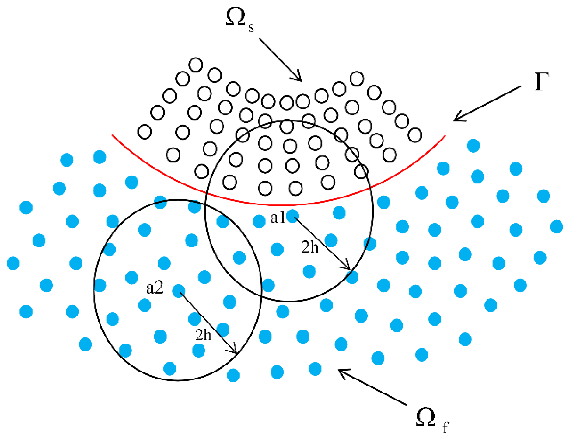
Two different SPH particles are used for fluids and solids, and when the particles are more than 2 h away from the fluid–solid interface, all of the particles interact only with the same kind of particles, but when the particles close to the interface are interpolated for SPH, both fluid and solid particles are involved. For viscous fluids, the XSPH [38] method and the introduction of no-slip boundary conditions can be used to define the coupled interface, but for the viscous fluids used in this paper, this method is not applicable; so, dynamic interface conditions and kinematic interface conditions must be introduced to deal with the coupled flow–solid interface. As shown in Figure 3.

2.4.1. Dynamic Interface Conditions

In order to make the flow–solid interface more recognizable without fragmentation, the line closest to the fluid particles and solid particles d/2 is defined as the flow–solid boundary. As shown in Figure 4. Dynamic boundaries essentially guarantee the principle of action–reaction by applying pressure, where the force of a fluid acting on a solid is equivalent to the force of a solid acting on a fluid of the same magnitude and in the opposite direction [35]. To obtain the SPH value of the force acting on the solid (fluid) by the fluid (solid), an approximation of the pressure gradient is made in the specified region:
p χ = p χ W χ χ , h Γ Ω + Ω p χ χ W χ χ , h d Ω
It can be obtained after SPH discretization:
p χ = Γ Ω p χ W χ χ , h d Γ + b m b ρ b p b a W a b
In fluid particles or solid particles in the domain of the nuclear function, Ω is defined in the same range as the domain of definition of the nuclear function Ω p χ χ W χ χ , h d Ω = 0 ; the nuclear function W is equal to 0 when χ χ = 2 h . In calculating the pressure gradient term for the solid boundary particle a, Equation (21) applies only to the solid domain and the particle associated with the solid boundary. At the same time, the fluid particle exerts a force per unit volume F f s , a on the solid particle a:
F f s , a = p int a Γ W χ int a χ , h d Γ
Among them,
p int a = 2 b Ω f m b ρ b p b W χ int a χ b , h
χ int a = χ a + r + 1 2 d n a
n a = t a y , t a x
t a = t a x ; t a y = χ a + 1 χ a 1 χ a + 1 χ a 1 , y a + 1 y a 1 y a + 1 y a 1
where Γ is the flowchart interface; t a is the tangential unit vector; χ a + 1 and χ a 1 are particles close to the front and back of particle a; n a is the normal unit vector; χ int a is the location of the interface point closest to particle a; r is the number of rows between particle a and the interface; Ω f is the fluid domain; and Ω s is the solid domain. p χ is the pressure gradient; W χ χ , h is the five-degree spline function; and Γ Ω is the fluid–solid interface.
A correction is made for the introduction of a unit mass force for particles at the solid boundary in the momentum equation of Equation (11):
d ν i a dt = b Ω s m b σ ij a ρ a 2 + σ ij b ρ b 2 + Π ab δ ij + R ij ab f q W ab a χ j + g i + F i f s , a ρ a
When performing numerical simulations, in the vast majority of cases, the positions of the fluid and solid particles at the boundary do not satisfy the symmetry condition; so, to satisfy the continuity of the positive stresses as they pass through the interface, action–reaction forces need to be applied:
F s f , a = F f s , a
Additionally, a correction is made for the introduction of a unit mass force for particles at the fluid boundary in the momentum equation of Equation (10):
d ν ia dt = b Ω f m b ( p a ρ a 2 + p b ρ b 2 ) δ i j W a b a χ j + g i + F i s f , a ρ a

2.4.2. Motion Interface Conditions

Define the velocity of a particle on a moving interface as
ν i inta = b Ω s m b ρ b ν i b W χ int a χ b ,   h b Ω s m b ρ b W χ int a χ b ,   h
The surface of the interface is actually a moving wall boundary for the fluid flow, and the velocity assignment of the fluid particles is carried out using the location of the solid particles. The normal vector of the required ν i inta at the fluid–solid interface is calculated using SPH interpolation.

3. Model Validation

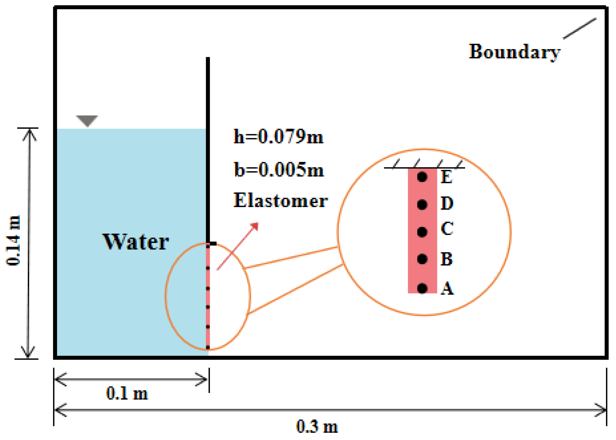
In order to verify the effectiveness of the program based on the physical model experiment’s related parameters outlined in [36], an elastic gate numerical model that combines the SPH method and finite element method is established. At the moment when the elastic gate constraints are lifted (time: 0 s), the dam-breaking water flow generated by the water pressure will cause the elastic gate’s continuous movement and deformation. In this paper, the numerical model of the fluid–solid interaction based on the SPH method and the finite element method and the experimental results from [36] will be compared and analyzed in terms of the flow regime of the water body, the gate opening, and the change in the free liquid level and the fluid–solid force. The initial arrangement of the model is shown in Figure 5, where a rectangular body of water with a length of 0.1 m and a height of 0.14 m is arranged in a rectangular tank measuring 0.3 m × 0.2 m. Rigid baffles and flexible gates control the flow of water, with gates measuring 0.079 m high and 0.005 m wide. In order to verify the force on the fluid–solid interface, five characteristic points of A, B, C, D, and E were selected along the gate with an equal spacing of 0.0158 m between them. The physical time selection is consistent with the experimental physical time presented in the literature, where the numerical simulation time is 0.4 s. The other calculation parameters related to the SPH model and finite element model are shown in Table 2.

3.1. Comparison of Water Flow Patterns

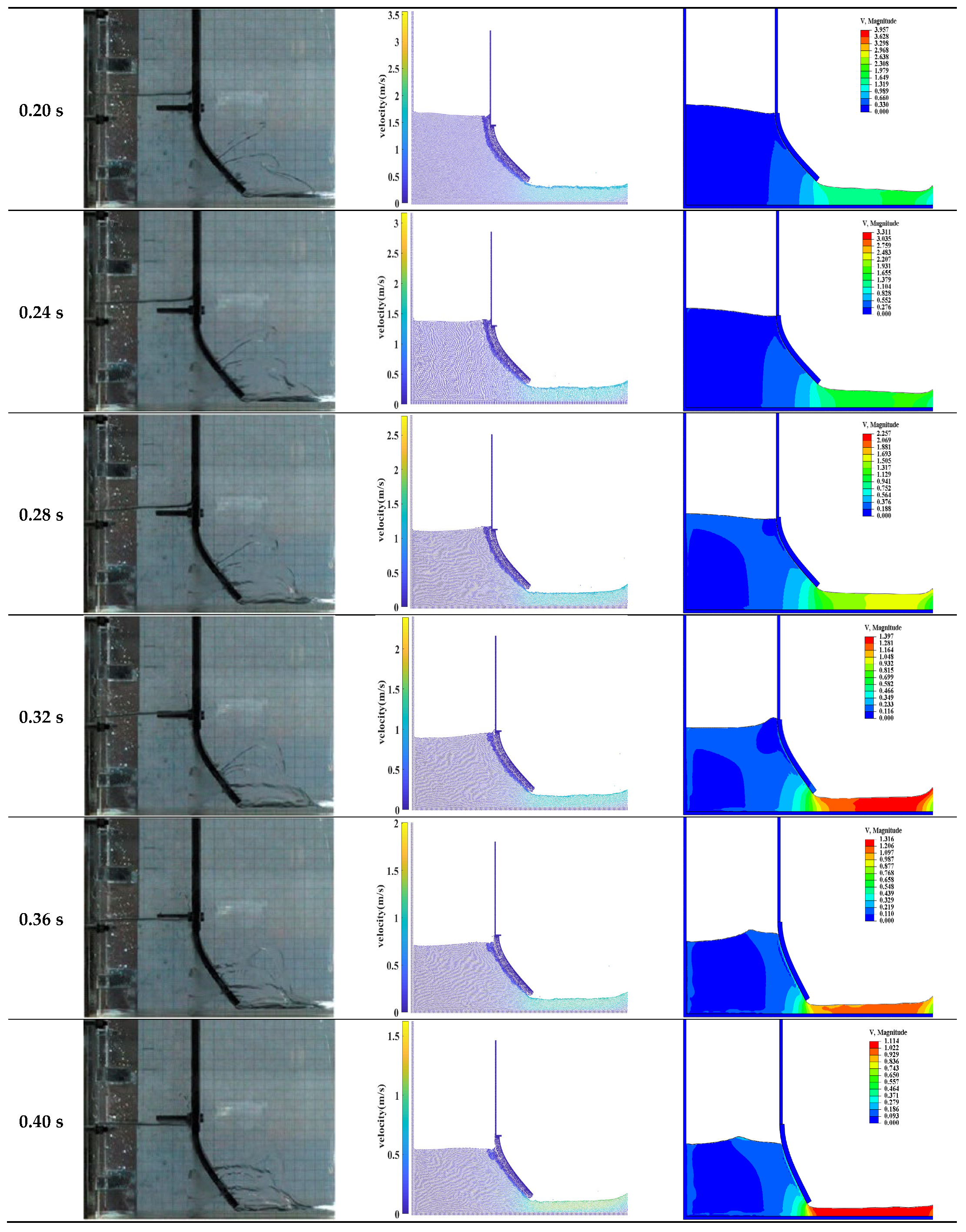
Based on the SPH method and FEM method, the elastic sluice gate opening was compared with the experimental data from [36], as shown in Figure 6. Before the sluice discharge water flow and elastic gate are in a static state, the sluice produces a discharge under the action of gravity. As the elastic gate is under the impact of a water flow that is constantly in motion, the gate is gradually opened, and a large deformation is produced. Analyzed from a qualitative and quantitative point of view, the degree of deformation of the gate at each moment during the numerical calculation of the SPH method and the finite element method is consistent with the trend of the opening of the gate in the experiment. The water flow is at a standstill at 0 s, when the velocity of the water flow is also zero; at 0.04 s, the elastic gate gradually opens, the maximum velocity of the water flow according to the SPH model is around 1.03 m/s, and the maximum flow velocity of the water flow according to the FEM model is around 1.09 m/s. At 0.08–0.12 s, the gate gradually opens, and the front end of the water flow reaches the maximum velocity and produces a certain amount of water jump; the maximum velocity of the water jump produced by the SPH method and the FEM method is 1.77 m/s and 1.83 m/s, respectively. At about 0.16 s, the gate opening reaches its maximum value, and the water velocity increases to 1.86 m/s and 1.92 m/s. In general, the water velocity under the FSI model based on the FEM method is slightly larger than that of the SPH model at all moments of the flow. After 0.2 s of the sluice gate discharging continuously, the water pressure behind the gate and the gate opening gradually decreased. At this time, the water flow velocity of the two numerical models reached the maximum value, and it was 3.56 m/s and 3.96 m/s. During the whole process from 0.24 s to 0.40 s, the gate opening and the water flow velocity were gradually reduced, in which the decay rate of the FEM model was larger than that of the SPH model. The water flow velocity of the SPH model decreased from 3.17 m/s to 1.63 m/s, with a decrease ratio of 51.4%, while the water flow velocity of the FEM model decreased from 3.31 m/s to 1.15 m/s, with a decrease ratio of 65.3%; the results from the two numerical methods coincided with the experimental results from the literature during the simulation process, which in turn indicates the effectiveness of the procedure. But the numerical model of fluid–solid coupling based on the finite element method (FEM) showed a more pronounced rate of change in the resilient gate recovery after 0.2 s, which is a deviation from the experimental results in the literature. This, in turn, indicates that the results of the numerical simulation based on the SPH method are closer to the experimental results.

3.2. Comparison of Gate Opening and Free Liquid Level

For the presentation of the simulation results of elastic sluice discharge, one of the important evaluation methods is comparing the displacement change curves of the gates under the action of water flow. In order to further investigate the difference between the SPH numerical simulation and finite element numerical simulation results and the experimental results, analyzing them from a quantitative point of view, the gate displacement change curves of these three methods are made by selecting the moment from 0 to 0.4 s, as shown in Figure 7.
In order to quantify the difference between the experimental results in the literature and the simulation results of the SPH method and the finite element method, the positional coordinates of the points were extracted from the transverse displacement curves and the longitudinal displacement curves of the elastomeric gate. The experimental data points were labeled as N1 and the numerical simulation data points as N2 using the similarity equation:
ε = 1 i = 1 N 1 y 1 i i = 1 N 2 y 2 i i = 1 N 1 y 1 i × 100 %
where y1i is the experimental data vertical coordinate values, and y2i is the value of the vertical coordinate of the simulation results.
Calculating the similarity of these three methods, the data show that the SPH model simulation results are in good agreement with the experiment results, and the numerical model of SPH can better simulate the elastic sluice discharge characteristics. The accuracy of the fluid–solid interaction procedure is verified.
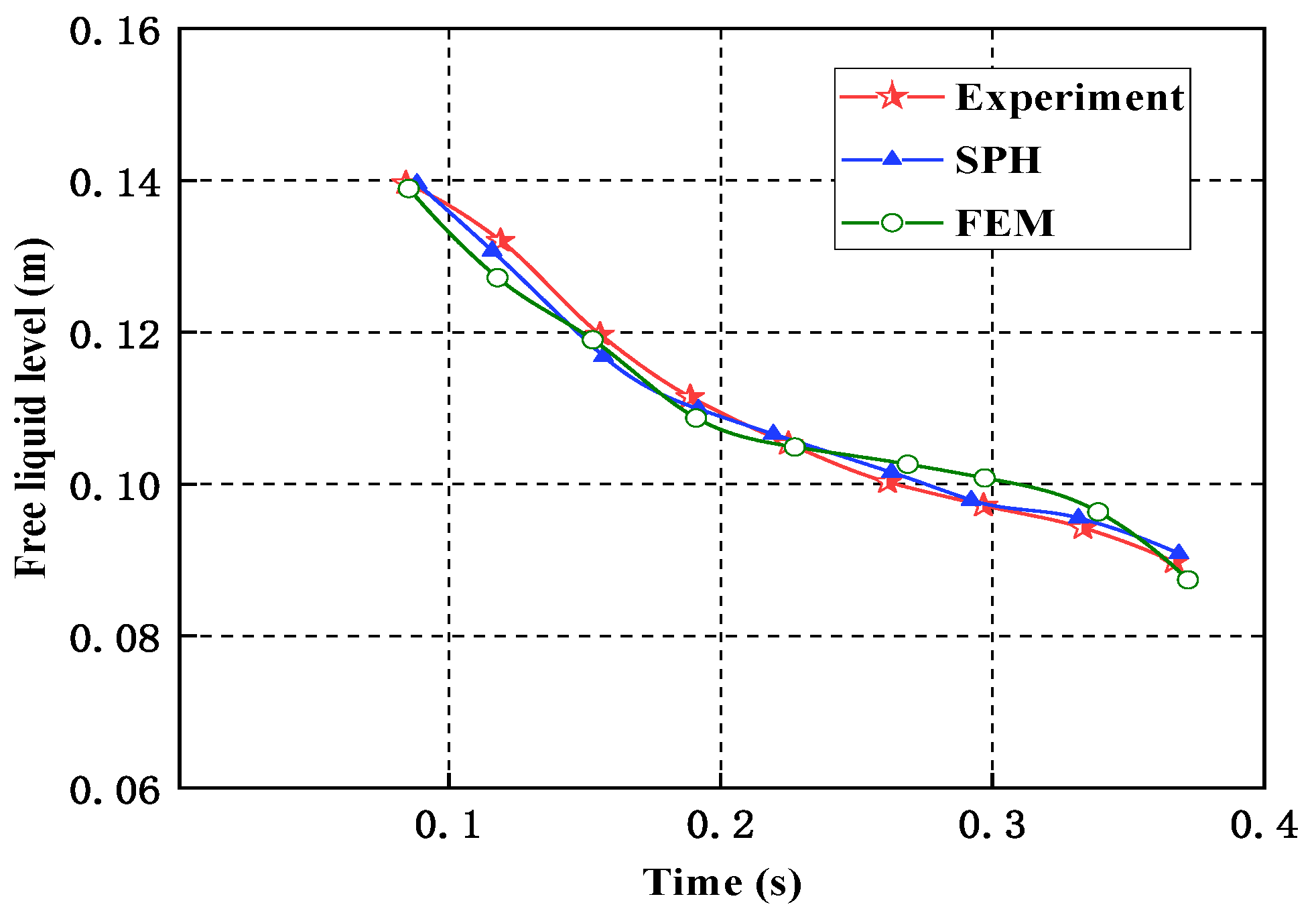
In order to further verify the validity and accuracy of the fluid–solid procedure, the two methods were compared with the experimental results from [34] with respect to the free surface profiles. Using the similarity formula, The calculation results are shown in Table 3. It was found that the SPH numerical simulation results are highly similar to the experimental results, with a 91.4% similarity, while the finite element calculation results are 85.7% similar to the experimental results; the three free liquid level curves are shown in Figure 8.

3.3. Fluid–Solid Pressure Comparison

This paper establishes a sluice discharge model based on the SPH method and the finite element method, and verifies the validity and accuracy of the SPH method in terms of the elastic gate displacement change characteristics and the free liquid surface height curve. Based on this, in order to verify that the fluid–solid dynamic boundary satisfies the action–reaction principle, five measurement points of A, B, C, D, and E are selected on the elastic plate to analyze the change rule of pressure of each measurement point and its surrounding water particles, to verify the validity of the nature of the dynamic boundary and the procedure, and to prepare for the subsequent study of the problems related to fluid–solid interactions.
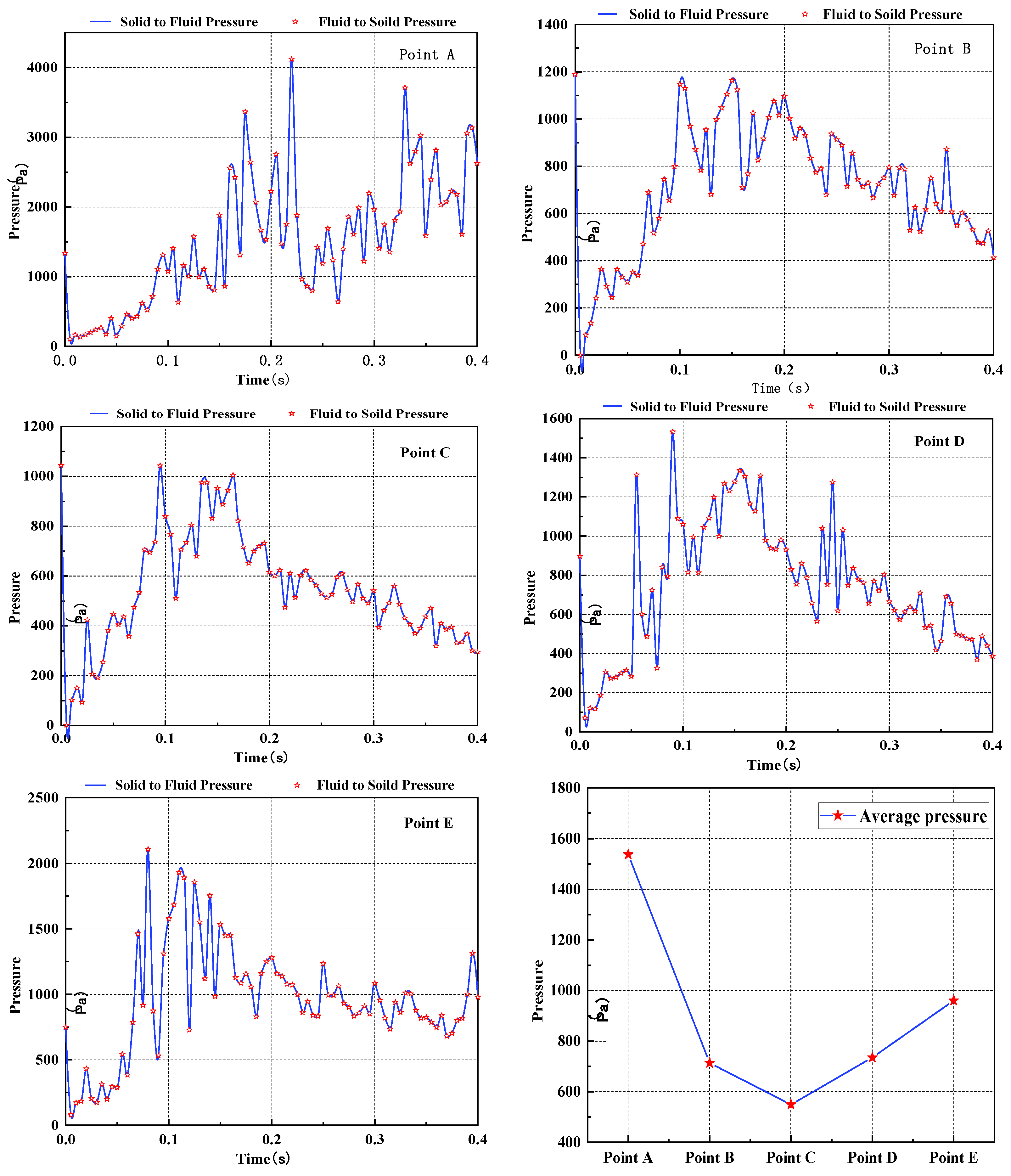
By selecting different measurement points on the elastic gate, we investigated whether the pressure of the solid on the fluid and the pressure of the fluid on the solid are equal, and analyzed the change rule of pressure, as shown in Figure 9. At different moments within 0–0.4 s, the pressure of the solid on the fluid is equal to the pressure of the fluid on the solid, which satisfies the action–reaction principle and verifies the nature of the dynamic boundary. The pressures at the initial moments of the measurement points A–D are 1336.72 Pa, 1191.92 Pa, 1044.77 Pa, 897.62 Pa, and 750.47 Pa. The pressure under the action of the fixed fluid increases with the increase in the depth of the water in the case of the same force area. Throughout the simulation process, the force at each measurement point shows a trend of first increasing and then decreasing. In the measurement points A–D, the maximum force is produced in decreasing order of 0.22 s, 0.15 s, 0.095 s, 0.09 s, and 0.08 s, and the elastic plate shows that the two ends of the force are large while the middle of the force is small. The elastic plate free end of measurement point A is the largest force, the middle of measurement point C is the smallest force, the fixed end of the force at measurement point E increases again, and the average pressure decreases from 1537.57 Pa to 549.02 Pa and then increases again to 959.99 Pa.

4. Conclusions

For the fluid–solid coupling-related problems, the SPH method is used to establish a classical sluice discharge model, and the changes in the flow pattern, gate opening, and free liquid surface curve of the water under various moments were analyzed. The advantages and innovations of this paper include comparing and analyzing the results of the SPH calculations with the results of the sluice discharge model established by the FEM method under the same kind of working conditions, as well as with the experimental data results in the literature. On this basis, in order to further verify the accuracy of the program, the changing law of the flow–solid pressure was studied, and the following conclusions were obtained:
1. A numerical model of fluid–solid coupling is established based on the SPH method. The Lagrange method is used to discretize the fluid and solid domains, the dynamic interface condition and the kinematic interface condition are introduced to deal with the fluid–solid coupling interface, and the particle velocity in the momentum conservation equation is corrected to improve the computational accuracy and to eliminate problems such as numerical instability for the particle velocity.
2. The problems related to sluice discharge are simulated under hydrostatic pressure, and the deformation of the elastic structure and the fluid flow process obtained are compared with the FEM method and the existing experiments, which proves that the results from the numerical model based on the SPH method are closer to the experimental results.
3. In the SPH model, the measurement point is selected to analyze the change in pressure at the fluid–solid interface, which reverse proves the fluid–solid dynamic boundary to satisfy the principle of action–reaction, further verifying the effectiveness of the program. At the same time, the elastic structure of the change rule of force is explored, the initial moment of the elastic baffle force increases with the increase in water depth, and the water flow against the elastic structure results in the two ends of the force being large while the middle of the force is small.

Author Contributions

J.Z. designed and developed the models and methods; B.W. analyzed the data and drafted the manuscript; Q.J. guided and supervised the whole process; G.H. provided suggestions for modifications; Z.L. and H.L. revised the manuscript. All authors have read and agreed to the published version of the manuscript.

Funding

This research was funded by the National Natural Science Foundation of China (52279133).

Data Availability Statement

The data presented in this study are available upon request from the corresponding author.

Conflicts of Interest

The authors declare no conflict of interest.

References

  1. Liu, M.; Zhang, Z. Smoothed particle hydrodynamics (sph) for modeling fluid-structure interactions. Sci. China Phys. Mech. Astron. 2019, 62, 1–38. [Google Scholar] [CrossRef]
  2. Wang, Y.; Gao, B.; Ren, W. Aerodynamic load and structure stress analysis on hood of high-speed railway tunnel. Chin. J. Theor. Appl. Mech. 2017, 49, 48–54. [Google Scholar]
  3. Liu, J.; Bao, X.; Tan, H.; Wang, J.; Guo, D. Dynamical artificial boundary for fluid medium in wave motion problems. Chin. J. Theor. Appl. Mech. 2017, 49, 1418–1427. [Google Scholar]
  4. Du, T.; Wang, Y.; Huang, C.; Liao, L. Study on coupling effects of underwater launched vehicle. Chin. J. Theor. Appl. Mech. 2017, 49, 782–792. [Google Scholar]
  5. Chen, W.; Fu, Y.; Guo, S.; Jiang, C. Fluid-solid coupling and dynamic response of vortex-induced vibration of slender ocean cylinders. Adv. Mech. 2017, 47, 25–91. [Google Scholar]
  6. He, T.; Zhang, K.; Wang, T. AC-CBS-based partitioned semi-implicit coupling algorithm for fluid-structure interaction using stabilized second-order pressure scheme. Commun. Comput. Phys. 2017, 21, 1449–1474. [Google Scholar] [CrossRef]
  7. Zhou, D.; He, T.; Tu, J. A modified CBS finite element approach for fluid-structure interaction. Chin. J. Theor. Appl. Mech. 2012, 44, 494–504. [Google Scholar]
  8. Chen, W.; Ji, C.; Xu, W. Numerical investigation on the asymmetric vibration and symmetry hysteresis of flow-induced vibration of two side-by-side cylinders. Chin. J. Theor. Appl. Mech. 2015, 47, 731–739. [Google Scholar]
  9. Sun, X.; Zhang, J.; Huang, B. An application of the cbs scheme in the fluid-membrane interaction. Chin. J. Theor. Appl. Mech. 2013, 45, 787–791. [Google Scholar]
  10. Liu, Z.; Nan, S.; Shi, Y. Hemodynamic parameters analysis for coronary artery stenosis of intermediate severity model. Chin. J. Theor. Appl. Mech. 2017, 49, 1058–1064. [Google Scholar]
  11. Bazilevs, Y.; Calo, V.M.; Hughes, T.J.R.; Zhang, Y. Isogeometric fluid-structure interaction: Theory, algorithms, and computations. Comput. Mech. 2008, 43, 3–37. [Google Scholar] [CrossRef]
  12. Antona, R.; Vacondio, R.; Avesani, D.; Righetti, M.; Renzi, M. Towards a High Order Convergent ALE-SPH Scheme with Efficient WENO Spatial Reconstruction. Water 2021, 13, 2432. [Google Scholar] [CrossRef]
  13. Capasso, S.; Tagliafierro, B.; Viccione, G. Application of an SPH-DEM Coupled Model for Elastic Fluid–Structure Interaction. Environ. Sci. Proc. 2022, 21, 34. [Google Scholar]
  14. Zhang, A.M.; Ming, F.R.; Wang, S.P. Coupled SPHS-BEM method for transient fluid-structure interaction and applications in underwater impacts. Appl. Ocean. Res. 2013, 43, 223–233. [Google Scholar] [CrossRef]
  15. Wu, K.; Yang, D.M.; Wright, N. A coupled SPH-DEM model for fluid-structure interaction problems with free-surface flow and structural failure. Comput. Struct. 2016, 177, 141–161. [Google Scholar] [CrossRef]
  16. Raymond, S.J.; Jones, B.; Williams, J.R. A strategy to couple the material point method(MPM) and smoothed particle hydrodynamics (SPH) computational techniques. Comput. Part. Mech. 2018, 5, 49–58. [Google Scholar] [CrossRef]
  17. Liu, F.; Yu, Y.; Wang, Q.; Luo, Y. A coupled smoothed particle hydrodynamic and finite particle method: An efficient approach for fluid-solid interaction problems involving free-surface flow and solid failure. Eng. Anal. Bound. Elem. 2020, 118, 143–155. [Google Scholar] [CrossRef]
  18. Yao, X.; Huang, D. PD-SPH modeling and analysis of fluid-structure interaction problem. Eng. Mech. 2022, 39, 17–25. [Google Scholar]
  19. He, T. Numerical simulation of fluid-structure interaction strong coupling based on ALE finite element method. Chin. J. Mech. 2018, 50, 395–404. [Google Scholar]
  20. Boscheri, W.; Dumbser, M. A direct Arbitrary-Lagrangian–Eulerian ADER-WENO finite volume scheme on unstructured tetrahedral meshes for conservative and non-conservative hyperbolic systems in 3D. J. Comput. Phys. 2014, 275, 484–523. [Google Scholar] [CrossRef]
  21. Liu, G.R.; Liu, M.B. Smoothed Particle Hydrodynamics: A Meshfree Particle Method; World Scientific: Singapore, 2003. [Google Scholar]
  22. Zienkiewicz, O.C.; Taylor, R.L. The Finite Element Method; McGraw-Hill: New York, NY, USA, 2000. [Google Scholar]
  23. Zhang, H.; Hao, Z.; Feng, Z. Application of lattice Boltzmann method in simulating droplet impact on liquid level. J. Hydraul. Eng. 2008, 39, 1316–1320. [Google Scholar]
  24. Wang, Z.; Li, D.; Hu, Y. An SPH stress correction algorithm and its application in free surface flow. Chin. J. Comput. Mech. 2017, 34, 101–105. [Google Scholar]
  25. Lu, W.; Fei, X.; Yang, Y. Improvement of the tensile instability in SPH scheme for the FEI (Fluid-Elastomer Interaction) problem. Eng. Anal. Bound. Elem. 2019, 106, 116–125. [Google Scholar]
  26. Liu, M.B.; Liu, G.R. Smoothed Particle Hydrodynamics (SPH): An Overview and Recent Developments. Arch. Comput. Methods Eng. 2010, 17, 25–76. [Google Scholar] [CrossRef]
  27. Avesani, D.; Dumbser, M.; Chiogna, G.; Bellin, A. Analternative smooth particle hydrodynamics formulation to simulate chemotaxis in porous media. J. Math. Biol. 2017, 74, 1037–1058. [Google Scholar] [CrossRef] [PubMed]
  28. Ng, K.C.; Low, W.C.; Chen, H.; Tafuni, A.; Nakayama, A. A three-dimensional fluid-structure interaction model based on SPH and lattice-spring method for simulating complex hydroelastic problems. Ocean Eng. 2022, 260, 112026. [Google Scholar] [CrossRef]
  29. Khayyer, A.; Gotoh, H.; Falahaty, H.; Shimizu, Y. An enhanced ISPH–SPH coupled method for simulation of incompressible fluid–elastic structure interactions. Comput. Phys. Commun. 2018, 232, 139–164. [Google Scholar] [CrossRef]
  30. Deng, L. Application of Variable-length Co-rotating Beam Element in Geometric Nonlinear Dynamic Analysis of Flexible Beam. Ph.D. Thesis, Dalian University of Technology, Dalian, China, 2021. [Google Scholar]
  31. Meng, Z.-F.; Zhang, A.-M.; Yan, J.-L.; Wang, P.-P.; Khayyer, A. A hydroelastic fluid–structure interaction solver based on the iemann-SPH method. Comput. Methods Appl. Mech. Eng. 2022, 429, 110028. [Google Scholar]
  32. Rakhshaa, M.; Pazoukib, A.; Serbana, R.; Negrut, D. Using a half-implicit integration scheme for the SPH-based solution of fluid–solid interaction problems. Comput. Methods Appl. Mech. Eng. 2019, 345, 100–122. [Google Scholar] [CrossRef]
  33. Yilmaz, A.; Kocaman, S.; Demirci, M. Numerical modeling of the dam-break wave impact on elastic sluice gate: A new benchmark case for hydroelasticity problems. Ocean Eng. 2021, 231, 108870. [Google Scholar] [CrossRef]
  34. Monaghan, J.J. Smoothed particle hydrodynamics. Rep. Progr. Phys. 2005, 68, 1703–1759. [Google Scholar] [CrossRef]
  35. Gray, J.P.; Monaghan, J.J.; Swift, R.P. SPH elastic dynamics. Comput. Methods Appl. Mech. Eng. 2001, 190, 6641–6662. [Google Scholar] [CrossRef]
  36. Antoci, C.; Gallati, M.; Sibilla, S. Numerical simulation of fluid-structure interaction by SPH. Comput. Struct. 2007, 85, 879–890. [Google Scholar] [CrossRef]
  37. Gallati, M.; Braschi, G. Simulazione Lagrangiana di flussi consuperficie libera in problemi di idraulica. L’acqua 2000, 5, 7–18. [Google Scholar]
  38. Vignjevic, R.; De Vuyst, T.; Campbell, J. The use of an homogeneous repulsive force for contact treatment in SPH. In Proceedings of the Fifth World Congress of Computational Mechanics WCCM V, Vienna, Austria, 7–12 July 2002. [Google Scholar]
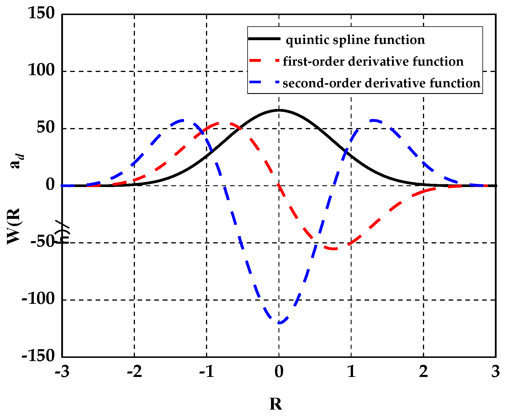
Figure 1. Quintic spline smooth kernel function and its derivatives.
Water 15 03738 g001
Figure 2. Comparison between simulation results and experimental free liquid level height curves for different λ values at t = 0.36 s in a classical dam failure problem.
Water 15 03738 g002
Figure 3. Fluid (blue) and solid (white) particles near the fluid–solid interface.
Water 15 03738 g003
Figure 4. Dynamic boundary conditions and solid particle a (White color represents solid particles and Blue color represents water particles).
Water 15 03738 g004
Figure 5. Schematic diagram of elastic gate discharge.
Water 15 03738 g005
Figure 6. Comparison of gate opening and water body flow pattern at different moments and with experimental results from [36].
Water 15 03738 g006aWater 15 03738 g006b
Figure 7. Comparison of gate transverse/longitudinal displacement results with experimental results from [34].
Water 15 03738 g007
Figure 8. Comparison of free liquid level curves with experimental results from [34].
Water 15 03738 g008
Figure 9. Comparison of pressure at each measurement point.
Water 15 03738 g009
Table 1. Comparison of similarity between numerical simulation results and experimental data.
λ λ = 0.97 λ = 0.93 λ = 0.88
Similarity84.1%91.9%88.3%
Table 2. Parameter conditions of SPH method of elastic gates in simulating the dam failure process.
Serial NumberCalculation ConditionParameter Value
1Particle spacing (m)0.001
2Number of particles in the water column17,997
3Number of elastomer particles1672
4Sidewall particle count2757
5Density of water (kg/m3)1000
6Density of elastic gate (kg/m3)1100
7Young’s modulus (N/m3)4.27 × 106
8Artificial stress factor (e,q)0.3 and 4
9Time step (s)5 × 10⁻⁶
10Physical time (s)0.4
Table 3. Comparison of similarity of numerical simulation results between SPH and FEM methods.
Numerical MethodSPH Method
X Displacement
FEM Method
X Displacement
SPH Method
Y Displacement
FEM Method
X Displacement
Similarity93.6%85.9%91.1%80.4%
Disclaimer/Publisher’s Note: The statements, opinions and data contained in all publications are solely those of the individual author(s) and contributor(s) and not of MDPI and/or the editor(s). MDPI and/or the editor(s) disclaim responsibility for any injury to people or property resulting from any ideas, methods, instructions or products referred to in the content.