Article

Mechanism Analysis of Floor Water Inrush Based on Criteria Importance though Intercrieria Correlation

1
College of Energy and Mining Engineering, Shandong University of Science and Technology, Qingdao 266590, China
2
State Key Laboratory of Coal Mining and Clean Utilization, Beijing 100013, China
3
College of Earth and Mineral Sciences, The Pennsylvania State University, State College, PA 16801, USA
*
Author to whom correspondence should be addressed.
Water 2023, 15(2), 232; https://doi.org/10.3390/w15020232
Submission received: 20 October 2022 / Revised: 9 December 2022 / Accepted: 23 December 2022 / Published: 5 January 2023
(This article belongs to the Topic Advances in Well and Borehole Hydraulics and Hydrogeology)

Abstract

:
Floor water inrush has always been an important problem affecting coal mine safety. The water inrush from the deep coal seam floor is the final manifestation of the water inrush channel formed by the expansion and penetration of rock mass cracks under the combined action of a high ground temperature, high ground stress, high karst water pressure and strong mining disturbance. The fault is a structurally weak plane developed in the complete rock layer, which can be regarded as a permeable channel with good permeability. In order to explore the location of confined water from the fault to rock stratum caused by the tensile fracture of a fault during floor water inrush, floor water inrush is regarded as the result of the joint action of water pressure and mining stress. The COMSOL Multiphysics numerical simulation software was used to simulate the advancing process of the working face of the coal seam with a fault structure. Different fault dip models were established for comparative analysis. The objective weight CRITIC based on data volatility was used to analyze the water pressure and principal stress near the fault. The results show that the uplift strength of highly confined water increases with the increase in the fault dip angle, and the weight of water pressure near the fault has a certain relationship with the location of the water body entering the rock stratum from the fault.

1. Introduction

China’s coal production reached 4.13 billion tons in 2021, accounting for 56% of its energy consumption. Coal continues to dominate the energy architecture. In the coming years, the energy system structure of the world, with coal resources as the main energy source, will not change. Regarding coal resources, after a long period of mining and consumption, shallow central coal mines have little left; in order to meet the demand for energy, coal mining is becoming gradually deeper. The deep mining of coal mines not only encounters complex geological structure conditions, but also involves the influence of high ground stress, a high karst water pressure and strong mining disturbance conditions [1,2,3]. According to statistics on the main reason for water inrush accidents in coal mines in China, water inrush accidents caused by fault activation account for more than 80% of the total water inrush accidents. As a non-continuous, non-homogeneous adverse geological structure often encountered in the process of coal mining, a fault is a highly permeable channel in the process of floor water inrush, which seriously threatens the layout of the working face and the safety of mine production [4,5,6]. As a common geological structure, a fault is one of the main factors causing mine water damage. Therefore, it is of certain guiding significance to study the water inrush path of the floor and the prevention and control of mine water damage to analyze the location of highly confined water entering the rock strata under the combined influence of a high ground temperature, high ground stress, a high karst water pressure and strong mining disturbance.
Wu Q. et al. [7] systematically divided the types of mine water disasters based on a classification system, which provided a basis for the classification and prevention of mine water disasters. Focusing on the core problem of mining, namely the complex geological structure and its induced high pressure water inrush, Guo W. et al. [8] divided the water inrush disaster modes of deep mining into three types: the complete floor fracture expansion type, the primary channel conduction type and the hidden structure sliding shear type. This was achieved with a theoretical analysis and comparative analysis of similar experiments and has great guiding significance for the study of water inrush in deep mining. Based on the theory of elastic damage mechanics, considering the different degrees of rock damage under different confining pressures, Sainoki A. et al. [9,10,11] studied the mechanism and law of seismic activity caused by fault activation under the influence of deep mining. A comparison between static analysis and dynamic analysis shows that the shear movement has a significant effect on the increase in deviatoric stress around the fault, which indicates that the fault is the main reason for the destruction of the rock mass and the formation of a seismic activity zone. Zhang P. et al. [12] used RFPA-FLOW two-dimensional numerical simulation software to simulate the process of floor fault activation and the final formation of delayed water inrush. Based on theoretical analysis and numerical simulation, the characteristics of floor fault activation and delayed water inrush induced by mining were studied in depth, and the mechanism of induced fault activation and delayed water inrush under the influence of mining was obtained.
In summary, the above results reflect the water inrush process of the fault-bearing coal seam floor to varying degrees, but few scholars have studied the location of fault tension cracks in the process of water inrush. Based on the above reasons, this study takes the change in the first principal stress and the water pressure data near the fault as the main research object. COMSOL software is used to simulate different faults to obtain principal stress and water pressure data along the fault. The objective weight is used to analyze the data, and the relationship between the change in water pressure weight and the location of fault tension is explored.

2. Mechanism Analysis of Fault Activation Water Inrush

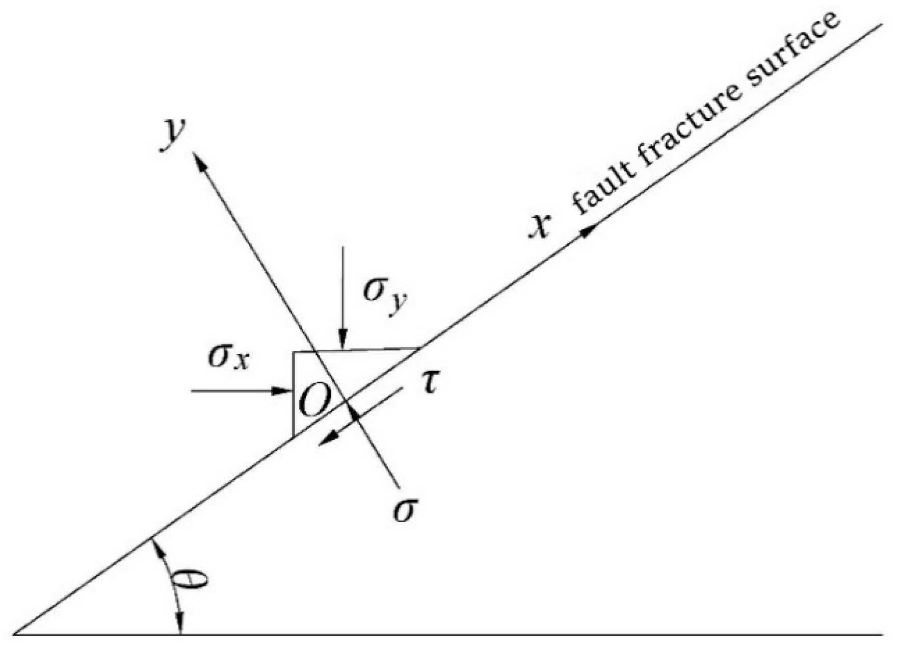
2.1. Analysis of Slip Mechanical Mechanism of Fault Plane

The mining of the coal seam near the fault plane destroys the original ground stress field, and the redistribution of ground stress is interrupted by the existence of the fault zone. It is of great theoretical and guiding significance to prevent coal mine water inrush and achieve mine pressure and rock stratum control by establishing a mechanical model of fault slip and analyzing the slip mechanics of the fault surface.
Because the strength of the rock mass in the fault zone is less than that of the rock mass in the upper and lower plates, the original micro-fractures of the rock mass in the fault zone are damaged and expanded in the fault zone under the mining action. After the original micro-fractures of the rock mass in the fault zone are expanded and penetrated, a fracture surface approximately parallel to the fault plane will be formed. Under the influence of mining, the fault will slip down along the fracture surface and cause the displacement difference of the fault. Taking the triangular micro-element with unit thickness on one side of the fault fracture surface as the research object, the fault slip mechanical model is established, as shown in Figure 1.
Before the slip of the rock mass in the fault zone caused by mining, the micro-element is static. The force analysis of the micro-element along the x and y directions shows
F x = σ x d s sin θ cos θ τ d s σ y d s cos θ sin θ = 0
F y = σ d s σ y cos θ cos θ σ x d s sin θ sin θ = 0
In the formula, ds is the contact area between the micro-element and the fracture surface; θ is the fault dip angle, unit °; σ is the normal stress of the rock mass to the micro-element, unit MPa; τ is the shear stress of the rock mass to the micro-element, unit MPa.
From the force equilibrium equation,
τ = σ x σ y sin θ cos θ
σ = σ x sin 2 θ + σ y cos 2 θ
Working face mining has a disturbance effect on the original stress balance of the coal and rock mass. When the working face is faced with a near-fault geological structure, the change in the stress balance state caused by mining activity will produce Coulomb stress f (σ,τ) on the fracture surface of the rock mass in the fault zone. When the Coulomb stress on the fracture surface reaches the ultimate shear strength τc of the rock mass in the fault zone, the relative friction dislocation of the rock mass in the fault zone will lead to the sliding of the rock mass in the fault zone. That is, the Coulomb stress f (σ,τ) of the fracture surface needs to satisfy
f σ , θ = | τ | ν σ > τ c
τ c = σ tan φ + c
In the formula, ν is the friction coefficient of the fracture surface; τc is the ultimate shear strength of the rock mass in the fault zone, unit MPa; φ is the internal friction angle of the rock mass in the fault zone, unit °; c is the cohesion of the rock mass in the fault zone, unit MPa.
It can be seen from Equation (5) that when the Coulomb stress on the fracture surface of the fault is greater than the ultimate shear strength, the rock mass of the fault zone is prone to slip. With the increase in the friction coefficient ν of the fracture surface, the smaller the Coulomb stress f (σ,τ) of the fracture surface caused by mining, the less likely the rock mass of the fault zone is to slip along the fracture surface, and the less likely the fault is to be activated. When the rock mass in the fault zone is water-bearing, water has a lubricating effect. The presence of water will reduce the friction coefficient ν between the fracture surfaces of the rock mass in the fault zone, and the Coulomb stress f (σ,τ) of the fracture surface caused by mining will increase. The rock mass in the fault zone is more prone to slip, which increases the possibility of fault activation. Therefore, it is necessary to detect the surrounding geological conditions in advance when passing through the fault during coal seam mining, and to explore the existence of aquifers near coal seams and faults, especially in deep coal seam mining. This is because, under the same conditions, with the increase in mining depth, the higher the groundwater pressure, the more significant the damage to the internal structure of the fault, so that the friction factor with the upper and lower rock masses of the fault zone is reduced. The water resistance capacity is correspondingly weakened, which increases the possibility of fault activation and further increases the possibility of water inrush from the coal seam floor.

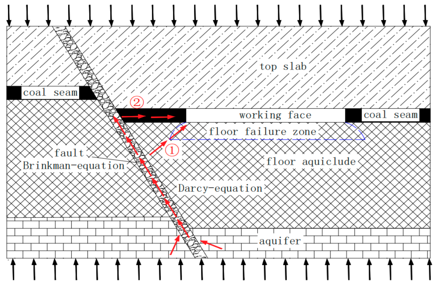
2.2. Water Inrush Path of Coal Seam Floor

After the mining of the coal seam, the formation process of the floor failure zone is actually that the complete floor strata along the advancing direction of the working face undergo the stages of advanced abutment pressure compression, shear slip deformation, pressure relief expansion and post-mining pressure compression, which leaves the original, relatively complete floor strata broken. Under the action of mine pressure, the mining plate of the fault experiences shear failure along the fault plane, which in turn causes new faults at one or both ends of the fault, so that the fault can be extended [13,14]. The key to whether the floor can undergo water inrush in the process of deep mine mining lies in the fact that the fracture develops, expands and penetrates to form a water inrush channel under the combined action of mine pressure and water pressure. The fracture of the fault occurs under the combined action of mine pressure and water pressure, which causes the high-pressure water to enter the rock layer from the fault, thus increasing the possibility of forming a water inrush channel [15,16].
By analyzing a large number of fault-containing floor water inrush accident data, it is found that the water inrush path leading to a floor water inrush accident is usually of the following two types, as shown in Figure 2. The reason for the water inrush in path 1 is that the floor aquifuge is destroyed under the influence of mining, which in turn causes the highly confined water to rise along the fault to a certain height and penetrate the floor failure zone to cause water inrush; the reason for water inrush in path 2 is that the texture of the coal seam is soft and the porosity is large. When the highly confined water body rises to the coal seam along the fault, the coal seam cannot block the confined water and cause water inrush.
When the coal seam is not excavated, it is in the original rock stress state, and the original stope stress balance is not affected by external forces; when the coal seam is excavated, the original rock stress state is broken due to the influence of mining, the stress of the stope is redistributed, and the stress at different working face positions is also different. According to the theory of mine pressure control and the theory of the “lower three zones” [17,18], in the process of coal mining, the floor strata in front of the working face are compressed under the action of advanced abutment pressure, and the complete floor strata undergo shear slip deformation. After coal seam mining, due to the failure of the roof strata of the working face to fall in time, the advance support pressure of the floor strata decreases sharply, and the floor strata expand. As the roof rock layer collapses, the floor rock layer is subjected to the gravity impact of the roof falling rock, and compression occurs again. Floor rock undergoes the compression- expansion–recompression process, resulting in the original, relatively complete rock’s deformation and failure, and the formation of a floor failure zone.
When confined water rises to a certain height in the fault, it enters the rock stratum at the location where the fault is fractured under the joint influence of water pressure and mining. Due to the influence of water pressure, the confined water breaking through the fault leads to cracks in the rock stratum. Under the combined influence of water pressure and stope pressure, the cracks are connected with the floor failure zone, and finally water inrush path 1 occurs. If the fault does not experience a tension crack or the tension crack location cannot be connected with the floor failure zone, confined water in the fault further guides the lift, because the texture of the coal seam is softer than the rock, and the coal seam’s internal voids and fissures push more confined water in the coal seam into the working face, and ultimately the formation of water inrush path 2 occurs.

2.3. Flow Field Control Equation

At present, the flow equations describing fluid flow in a broken rock mass mainly include the Darcy equation and nonlinear seepage equation. The Darcy equation only considers the influence of pressure difference and permeability on fluid flow, which is suitable for the seepage flow of fluid in aquifers and rock mass fractures before water inrush in a mine. It can also be used for the flow of confined water in the fault before the fracture zone in the fault is fully activated. When the fluid breaks through the restriction of the aquiclude to form a complete flow path, the fluid flow changes from linear to nonlinear, and the Darcy equation is no longer applicable.
The flow of groundwater in the aquifer changes linearly, which satisfies the application requirements of the Darcy equation. The transient equation [19] can be expressed as
t ρ φ + × ρ u = Q m
  u = k η p + ρ g H
φ = φ 0 1 + c φ × Δ p
In the formula, u is the fluid velocity, unit m/s; k is the permeability, unit m2; η is the dynamic viscosity coefficient, unit Pa·s; p is the fluid pressure, unit Pa; H is the position head, unit m; ρ is the fluid density, unit kg/m3; g is the acceleration of gravity, generally taken as 9.81 m/s2; is the gradient operator; Q m is the source–sink term; φ 0 is the initial value of porosity; c φ is the pore compression coefficient; Δ p is the pressure difference.
The fluid flows in the discontinuous medium. When the flow speed is fast enough, the energy loss caused by the shear action cannot be ignored, which requires the shear stress of the viscous fluid to be considered. H. C. Brinkman added the shear stress term of fluid viscosity to the Darcy equation and proposed the Brinkman equation based on Newton’s second law. The equation explains the motion law of the fluid under the action of shear force and osmotic pressure formed by the rapid flow of fluid in discontinuous media. The equation has strong applicability for describing the transition region between Darcy flow and fluid pipe flow in porous media. The Brinkman equation has a good effect in the theoretical analysis of the non-Darcy effect in porous media and the simulation of practical engineering problems, which is more suitable for the characteristics of non-Darcy rapid seepage in the fault fracture zone [20]. The Brinkman equation can be expressed as
u η k = p I + η u + u T + F u = 0
In the formula, I is the unit matrix.
The Darcy equation is mainly driven by fluid pressure, which is suitable for low-seepage porous media. Before the formation of a water inrush channel, the flow velocity of the fluid in the aquifer is low, which can be calculated by this equation. The Brinkman equation can be used to calculate the fracture scale and fluid velocity in the fault fracture zone.

3. Numerical Simulation Study

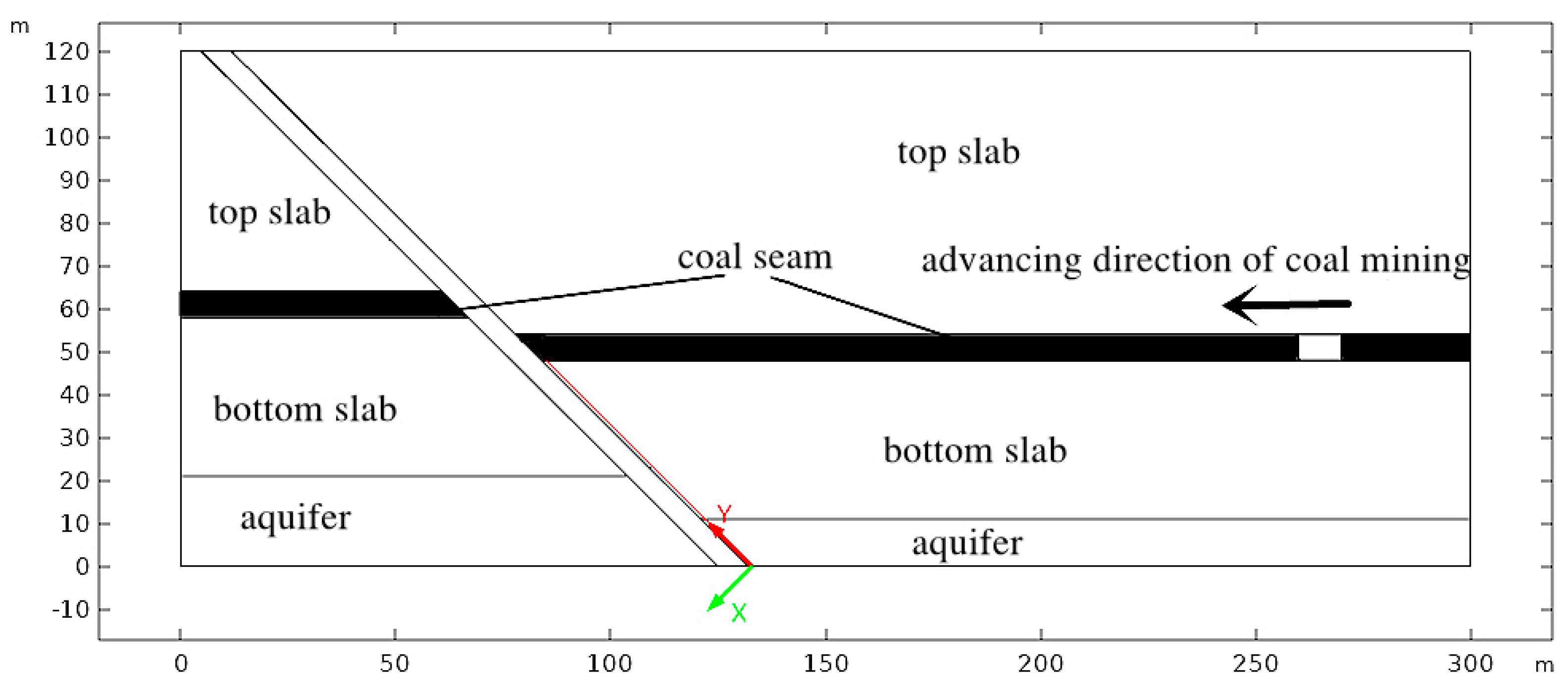
3.1. Establishing a Numerical Simulation Model

Based on the actual geological data of a mining area in Jining City, China, a numerical model was established according to the geological data and rock properties of the mine. The numerical software COMSOL Multiphysics was used for simulation. The length of the model coordinate in the Y-direction was 120 m, and the top of the model was 600 m from the surface. The fault width was 5 m, and the fault dip angles were set to 30°, 45° and 60°, respectively. Considering the influence of different fault dip angles on the model size, the X-direction length of the 30° fault dip model coordinate was set to 350 m; the length of 45° and 60° fault dip model coordinates in the X-direction was set to 300 m. In order to prevent the influence of mining on the boundary of the model, a 30 m boundary coal pillar was set at the boundary of the 30° and 45° model. A 40 m boundary coal pillar was set at the boundary of the 60° model. A safety coal pillar with a width of around 90 m was left near the fault, and the excavation direction of the coal seam was advanced in the opposite direction of the X axis. For the simulation of a coal seam thickness of 6m, a full mining height, a single excavation at 10 m and excavation steps of 10, the model’s mechanical parameters and the numerical model are shown in Table 1 and Figure 3.
The boundary condition of the model is that the horizontal displacement of the two ends is fixed to 0, the horizontal displacement and vertical displacement of the bottom boundary of the model are fixed to 0, and the top boundary of the model is a free boundary. Water pressure of 7 MPa is applied to the bottom boundary of the model. Applying the equivalent load at the top of the model—that is, the self-weight stress of the overlying strata—the value can be obtained as follows:
σ = γh
In the formula, γ is the volume force of overlying strata, taken as 25 KN/m3; h is the height from the top of the model to the surface, unit m.
In order to obtain the values of the principal stress and water pressure near the fault and analyze the relationship between the two, a monitoring line is added along the fault with the bottom of the model to the coal seam to record the water pressure and the first principal stress. The position of the monitoring line is shown in Figure 4. The red line along the fault is the monitoring line; the origin of the coordinate axis is the endpoint of the monitoring line.

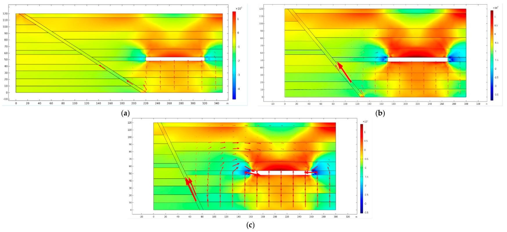
3.2. Analysis of Floor Seepage Field

In order to analyze the influence of the fault dip angle of the coal seam floor on the process of confined water lifting and the relationship between the water pressure weight and fault tension fracture position, three different fault dip angle models of 30°, 45° and 60° were designed in the scheme. The seepage fields of the 30° fault dip angle, 45° fault dip angle and 60° fault dip angle when the advancing distance of the stope is 100 m were selected to analyze the influence of different fault dip angles on the seepage and lifting of confined water in the floor aquifer.
In Figure 5, the background is the first principal stress cloud map, and the red arrow indicates the direction and size of the seepage. Because the water body of the confined aquifer of the floor is subjected to the combined action of mining stress and high water pressure, the confined water of the aquifer has a certain uplift in the aquiclude, but the uplift strength and range are limited. The fault has good water conductivity compared with the intact rock layer, and the uplift route of the confined water of the aquifer is still dominated by the fault. The existence of faults is conducive to the uplift of highly confined water in the floor aquifer under the influence of mining; in particular, when the dip angle of faults gradually increases, the uplift strength of the highly confined water also increases.

4. Data Analysis

4.1. CRITIC Weights

The Criteria Importance Though Intercrieria Correlation (CRITIC) weighting method is an objective weighting method based on the amount of data. The idea is to compare the two indicators of strength and conflict. Contrast intensity is represented by the standard deviation; if a greater standard deviation of the data indicates greater volatility, the weight will be higher. The conflict is represented by the correlation coefficient. If the correlation coefficient between the indicators is larger, the conflict is smaller, and the weight is lower [21,22]. CRITIC weights apply to indicators or factors that are related to each other. The weight calculation process is as follows.
Step 1: Construct the original data matrix:
X = x 11 x 1 m x n 1 x n m
In the formula, X is the original data matrix; n is the number of evaluation objects; m is the number of evaluation indicators.
Step 2: Dimensionless processing—select the maximum value method for processing:
X i = x i min ( x i ) max ( x i ) min ( x i )
In the formula, X i is the value after normalization of the ith data; x i is the value before normalization of the ith data; m i n ( x i ) is the minimum value before normalization of the ith data; m a x ( x i ) is the maximum value before normalization of the ith data.
Step 3: Index variability calculation—index variability is expressed by the standard deviation:
x ¯ j = 1 n i = 1 n x i j S j = i = 1 n ( x i j x ¯ j ) 2 n 1
In the formula, x ¯ j is the mean of the jth indicator; i, j is the row and column in the original matrix; Sj is the standard deviation of the jth indicator.
Step 4: Index conflict calculation:
R j = i = 1 m ( 1 r i j )
In the formula, rij is the correlation coefficient between the ith indicator and the jth indicator.
Step 5: Information quantity calculation:
C j = S j × R j
Step 6: Calculation of objective weights:
W j = C j j = 1 m C j
In the formula, Wj is the objective weight of the jth indicator.

4.2. Weight Analysis

For every 10 m that the coal seam working face advances, the monitoring line records data once. The simulated mining process advances a total of 100 m, and the monitoring line records 10 instances of data. The numerical changes of the first principal stress and water pressure near the fault during mining are shown in Figure 6. It is difficult to see the relationship between the principal stress and water pressure.
The monitoring line data of the 30°, 45° and 60° fault dip angles were counted and organized. The monitoring points at the same position of the monitoring line recorded the data of 10 steps of excavation—that is, the data of each monitoring point included 10 principal stress data and 10 water pressure data. The CRITIC weight was further used to calculate the principal stress–water pressure weight at different positions on the monitoring line. In order to ensure the influence of the number of data on the calculation of the weight results, the data collected by the five adjacent monitoring points on the monitoring line were calculated as a group, and the settlement results are shown in Figure 7.
It can be seen from the above diagram that, in the first stage, the weight of water pressure at the bottom of the fault is higher. With the increase in height, the weight decreases as a whole, while the weight of principal stress changes in the opposite direction. In the second stage, the weight of water pressure is maintained below 50, and the overall trend is no longer decreasing. In the third stage, as the distance from the coal seam becomes smaller, the water pressure weight increases as a whole.
Considering the two most common water inrush paths, where one is based on the shortest path of the fault fracture zone and floor failure zone through the path and the second is due to the softer texture of the coal seam, there are more internal pores and fissures that form the water inrush path. It can be seen from the change in water pressure weight in Figure 7 that the stage with a large water pressure weight is basically consistent with the location of highly confined water entering the rock stratum or coal seam from the fault under the two water inrush paths—that is, in the process of highly confined water lifting, the size of the water pressure weight can reflect the location of fault tensile water entering the rock stratum or coal seam from the fault.

5. Discussion

In the process of deep coal mining, floor water inrush is an important factor threatening the safety of mine production. The main influencing factors in the process of floor water inrush are mining stress and water pressure, so many experts have studied fluid–solid coupling and water–rock interactions. Shang D. et al. [23,24,25] studied the physical and chemical interactions between a chemical solution and granite fracture to understand the influence of the water–rock interaction on the mechanical properties of the fractured rock mass. Therefore, this paper used the CRITIC weight to analyze the relationship between water pressure and principal stress and predict the location of water inrush through the change in water pressure weight.
The analysis method can be further improved. In this paper, it is considered that floor water inrush is the result of the joint action of the coal seam floor, floor-confined water and mining stress. The mining-induced rock pressure causes a certain depth of water-conducting cracks in the floor aquifuge, reduces the strength of the rock mass, weakens the water-resisting performance and causes the redistribution of the seepage field of the floor. When the confined water is further immersed along the water-conducting fracture, the rock mass continues to expand due to water softening, until the result of the interaction between the two is enhanced to the bottom rock mass to produce fracturing expansion, and water inrush occurs through the water inrush channel. The dynamic mechanism of water inrush is revealed, but no quantitative conclusion can be drawn on the re-conduction of the mining-induced water-conducting fracture zone and confined water and the tensile strength of the rock mass.
At present, the research method only analyzes the objective weight of water pressure and mining stress, and the research object is relatively small. In future research, the research object can be appropriately increased, and the method of comprehensive analysis of subjective weights and objective weights can be adopted to make the results more accurate and scientific, thus promoting the process of mine intelligence.

6. Conclusions

(1) A mechanical model of fault slip is established according to the expansion law of rock micro-cracks in the fault zone under the action of mining. With the advancement of the working face, the stress caused by mining activities will promote the activation of faults, and the highly confined water in faults can easily promote the activation of faults and induce floor water inrush disasters.
(2) By comparing the seepage fields of 30°, 45° and 60° fault dip angles, it can be seen that the fault can be used as a water inrush channel with good permeability. The existence of the fault is conducive to the migration and uplift of the highly confined water in the floor aquifer under the influence of mining, and the fault dip angle is proportional to the uplift strength of the highly confined water.
(3) By analyzing the weight of water pressure and principal stress near the fault, it is found that the weight of water pressure near the fault can reflect the location of the fault tension fracture. The CRITIC weight can be used to analyze the fluctuation in the water pressure weight near the fault to analyze the location of highly confined water entering the rock layer from the fault.
(4) The method of the objective weight analysis of water pressure at different locations can predict the location of water inrush, which has certain reference value for the analysis of water inrush paths and the prevention of mine floor water inrush accidents.

Author Contributions

Conceptualization, W.S. and H.L.; Data curation, H.L. and Z.C.; Methodology, H.L. and H.Y.; Writing—original draft, H.L.; Writing—review and editing, W.S., Z.C., H.Y. and J.L. All authors have read and agreed to the published version of the manuscript.

Funding

This research was funded by the Taishan Scholars Program. This research was supported by the National Natural Science Foundation of China (No. 51974172, 52274131), the Shandong Provincial Natural Science Foundation Project (ZR2019MEE004, 0203100011301) and the State Key Laboratory of Coal Mining and Clean Utilization (2021-CMCU-KF017).

Institutional Review Board Statement

Not applicable.

Informed Consent Statement

Not applicable.

Data Availability Statement

Not applicable.

Conflicts of Interest

The authors declare no conflict of interest.

References

  1. Wu, Q. Progress, problems and prospects of prevention and control technology of mine water and reutilization in China. J. China Coal Soc. 2014, 39, 795–805. [Google Scholar]
  2. Sun, W.; Du, H.; Zhou, F.; Shao, J. Experimental study of crack propagation of rock-like specimens containing conjugate fractures. Geomech. Eng. 2019, 17, 323–331. [Google Scholar]
  3. Zhang, S.; Guo, W.; Sun, W. Experimental research on extended activation and water inrush of concealed structure in deep mining. Rock Soil 2015, 36, 3111–3120. [Google Scholar]
  4. Yu, Q.; Zhang, H.; Zhang, Y. Analysis of fault activation mechanism and influencing factors caused by mining. J. China Coal Soc. 2019, 44, 18–30. [Google Scholar]
  5. Sun, W.; Xue, Y.; Li, T.; Liu, W. Multi-field coupling of water inrush channel formation in a deep mine with a buried fault. Mine Water Environ. 2019, 38, 528–535. [Google Scholar] [CrossRef]
  6. Zhu, G.; Du, L.; Liu, Y. Dynamic analysis and numerical simulation of fault slip instability induced by coal extraction. J. China Univ. Min. Technol. 2016, 45, 27–33. [Google Scholar]
  7. Wu, Q.; Liu, Y.; Liu, D.; Zhou, W. Prediction of floor water inrush: The application of GIS-based AHP vulnerable index method to Donghuantuo coal mine, China. Rock Mech. Rock Eng. 2011, 44, 591–600. [Google Scholar] [CrossRef]
  8. Guo, W.; Zhang, S.; Sun, W. Experimental and analysis research on water inrush catastrophe mode from coal seam floor in deep mining. J. China Coal Soc. 2018, 43, 219–227. [Google Scholar]
  9. Sainoki, A.; Mitri, H.S. Effect of fault-slip source mechanism on seismic source parameters. Arab. J. Geosci. 2016, 9, 1–12. [Google Scholar] [CrossRef]
  10. Sainoki, A.; Mitri, H.S. Influence of undulating fault surface properties on its seismic waves during fault-slip. Int. J. Min. Reclam. Environ. 2016, 30, 1–12. [Google Scholar] [CrossRef]
  11. Sainoki, A.; Mitri, H.S.; Chinnasane, D. Characterization of Aseismic Fault-Slip in a Deep Hard Rock Mine Through Numerical Modelling: Case Study. Rock Mech. Rock Eng. 2017, 50, 2709–2729. [Google Scholar] [CrossRef]
  12. Zhang, P.; Zhu, X.; Sun, W. Study on mechanism of delayed water inrush caused by mining-induced filling fault activation. Coal Sci. Technol. 2022, 50, 136–143. [Google Scholar]
  13. Wang, S.; Ma, Q.; Fan, X. Numerical simulation study on floor water inrush mechanism under influence of fault. Coal Technol. 2020, 39, 112–115. [Google Scholar]
  14. Liu, S.; Liu, W.; Yin, D. Numerical simulation of the lagging water inrush process from insidious fault in coal seam floor. Geotech. Geol. Eng. 2017, 35, 1013–1021. [Google Scholar] [CrossRef]
  15. Jiao, Z.; Zhao, Y.; Jiang, Y. Fault damage induced by mining and its sensitivity analysis of influencing factors. J. China Coal Soc. 2017, 42, 36–42. [Google Scholar]
  16. Song, Z.; Hao, J.; Tang, J. Study on water inrush from fault’s prevention and control theory. J. China Coal Soc. 2013, 38, 1511–1515. [Google Scholar]
  17. Gao, M.-T.; Song, Z.-Q.; Yu, W.-B.; Duan, H.-Q.; Xin, H.-Q.; Tang, J.-Q. Overlying Strata Structure Evolution and Engineering Practice Based on the Mining of Lower Liberating Seam in Deep Bursting Coal Seam Group. Geotech. Geol. Eng. 2021, 39, 3293–3314. [Google Scholar] [CrossRef]
  18. Xu, Y.; Zhang, E.; Luo, Y.; Zhao, L.; Yi, K. Mechanism of water inrush and controlling techniques for fault-traversing roadways with floor heave above highly confined aquifers. Mine Water Environ. 2020, 39, 320–330. [Google Scholar] [CrossRef]
  19. Yang, T.; Shi, W.; Li, S. State of the art and trends of water-inrush mechanism of nonlinear flow in fractured rock Mass. J. China Coal Soc. 2016, 41, 1598–1609. [Google Scholar]
  20. Li, L.; Yang, T.; Liang, Z.; Zhu, W.; Tang, C. Numerical investigation of groundwater outbursts near faults in underground coal mines. Int. J. Coal Geol. 2011, 85, 276–288. [Google Scholar]
  21. Diakoulaki, D.; Mavrotas, G.; Papayannakis, L. Determining objective weights in multiple criteria problems: The critic method. Comput. Oper. Res. 1995, 22, 763–770. [Google Scholar] [CrossRef]
  22. Wu, H.W.; Zhen, J.; Zhang, J. Urban rail transit operation safety evaluation based on an improved CRITIC method and cloud model. J. Rail Transp. Plan. Manag. 2020, 16, 100206. [Google Scholar] [CrossRef]
  23. Shang, D.; Zhao, Z.; Dou, Z.; Yang, Q. Shear behaviors of granite fractures immersed in chemical solutions. Eng. Geol. 2020, 279, 105869. [Google Scholar] [CrossRef]
  24. Liu, C.; Zhang, D.; Shang, D.; Zhao, H.; Song, Z.; Yu, H. Influence of confining pressure unloading at post-peak on deformation and permeability characteristics of raw coal. Rock Soil Mech. 2018, 39, 2017–2024+2034. [Google Scholar]
  25. Chen, C.; Peng, S.; Xu, J.; Tang, Y.; Shang, D. Experimental study of stress relaxation characteristics of sandstone under stress and pore-water pressure coupling. Chin. J. Rock Mech. Eng. 2022, 41, 1193–1207. [Google Scholar]
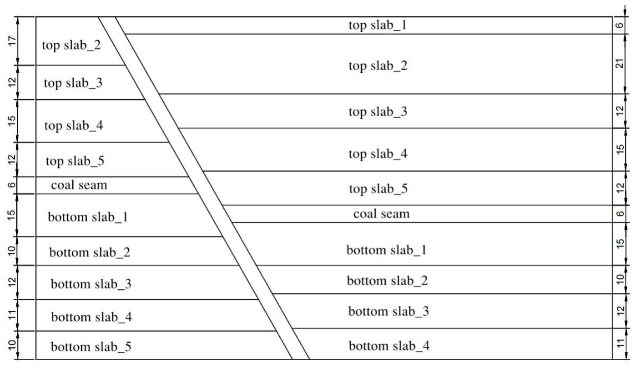
Figure 1. Mechanical model of fault plane slip.
Water 15 00232 g001
Figure 2. Water inrush path diagram containing fault floor.
Water 15 00232 g002
Figure 3. Numerical simulation model.
Water 15 00232 g003
Figure 4. Location of monitoring line.
Water 15 00232 g004
Figure 5. Different fault dip seepage fields. (a) 30° fault dip seepage field. (b) 45° fault dip seepage field. (c) 60° fault dip seepage field.
Water 15 00232 g005
Figure 6. Water pressure values and principal stress values. (a) 30 ° fault dip water pressure. (b) 30° fault dip first principal stress. (c) 45° fault dip water pressure. (d) 45° fault dip first principal stress. (e) 60° fault dip water pressure. (f) 60° fault dip first principal stress.
Water 15 00232 g006
Figure 7. Water pressure and principal stress weight diagram. (a) 30° fault dip water pressure and principal stress weight. (b) 45° fault dip water pressure and principal stress weight. (c) 60° fault dip water pressure and principal stress weight.
Water 15 00232 g007
Table 1. Mechanical parameters of model.
Group NameThickness
/m
The Angle of Internal Friction
(°)
Elastic Modulus
/GPa
Poisson’s RatioCohesion
/MPa
Tensile Strength
/MPa
Density
(g/cm3)
PermeabilityPorosity
top slab_16363.50.343.00.322.513.21 × 10−90.200
top slab_221405.20.265.10.412.531.50 × 10−90.100
top slab_312392.80.312.40.312.605.46 × 10−90.050
top slab_415385.50.345.20.412.612.45 × 10−90.100
top slab_512393.20.342.40.222.553.25 × 10−90.050
bottom slab_115405.00.295.00.502.511.00 × 10−100.001
bottom slab_210414.70.313.80.422.531.00 × 10−100.001
bottom slab_312383.60.362.20.212.601.00 × 10−100.001
bottom slab_411393.70.332.60.352.531.00 × 10−100.001
bottom slab_510373.60.332.90.332.541.00 × 10−100.001
fault/302.40.381.50.251.255.00 × 10−100.500
coal seam6283.00.361.60.301.332.45 × 10−100.100
Disclaimer/Publisher’s Note: The statements, opinions and data contained in all publications are solely those of the individual author(s) and contributor(s) and not of MDPI and/or the editor(s). MDPI and/or the editor(s) disclaim responsibility for any injury to people or property resulting from any ideas, methods, instructions or products referred to in the content.

