Article

Value of Spatially Distributed Rainfall Design Events—Creating Basin-Scale Stochastic Design Storm Ensembles

1
Department of Built Environment, School of Engineering, Aalto University, FI-00076 Aalto, Finland
2
Finnish Environment Institute (Syke), Climate Solutions, Hydrological Forecasting, Latokartanonkaari 11, FI-00790 Helsinki, Finland
*
Author to whom correspondence should be addressed.
Water 2023, 15(17), 3066; https://doi.org/10.3390/w15173066
Submission received: 17 July 2023 / Revised: 17 August 2023 / Accepted: 23 August 2023 / Published: 27 August 2023
(This article belongs to the Section Hydrology)

Abstract

:
Current design storms used in hydrological modeling, urban planning, and dimensioning of structures are typically point-scale rainfall events with a steady rainfall intensity or a simple temporal intensity pattern. This can lead to oversimplified results because real rainfall events have more complex patterns than simple design series. In addition, the interest of hydrologists is usually in areal estimates rather than point values, most commonly in river-basin-wide areal mean rainfall estimates. By utilizing weather radar data and the short-term ensemble prediction system pySTEPS, which has so far been used for precipitation nowcasting, ensembles of high-resolution stochastic design storms with desired statistical properties and spatial structure evolving in time are generated. pySTEPS is complemented by adding time-series models for areal average rainfall over the simulation domain and field advection vectors. The selected study area is the Kokemäenjoki river basin located in Western Finland, and the model parametrization is carried out utilizing the Finnish Meteorological Institute’s weather radar data from the years 2013 to 2016. The results demonstrate how simulated events with similar large-scale mean areal rainfall can produce drastically different total event rainfalls in smaller scales. The sampling method, areal vs. gauge estimate, is also shown to have a prominent effect on total event rainfall across different spatial scales. The outlined method paves the way towards a more thorough and wide-spread assessment of the hydrological impacts of spatiotemporal rainfall characteristics.

1. Introduction

Information about the amount, intensity, and duration of rainfall is the basis for most hydrological assessments. Evaluation of runoff response to large rainfall events is one of the main hydrological applications, and hydrologists are interested in rainfall intensity changes and variations on a small scale. Runoff response is studied utilizing rainfall–runoff models, where rainfall is a key input.
Currently an often-used data source in rainfall–runoff studies is traditional rainfall measurements with rain gauges [1,2]. Their benefits are low cost for individual gauges, ease of operation, and accurate point measurements at high temporal resolutions. However, for dense gauge networks, the costs of maintaining a large number of measuring instruments in various locations can become very expensive. In addition to rain gauges, weather radars are also used to measure rainfall. The main advantage of using weather radars is that more rainfall events can be detected, as the areal coverage of a radar is much larger than that of typical rain gauge networks [3]. Moreover, radars enable real-time rainfall applications and nowcasting, as well as providing the basis for areal rainfall estimations [4].
Radars have been used for measuring rainfall for decades. The problems have been the poor quality of rain products and the large amount of data, which have previously made data analysis uncertain and calculations heavy to handle with available computing resources. Moreover, radar measures the backscattered signal from rainfall in a sample volume, including echoes not only from precipitation, but also from non-meteorological sources, such as insects, birds, and aircraft [5]. Polarimetric techniques enable the removal of non-meteorological echoes from the data and improve radar rain estimates by identifying the precipitation type [6]. However, these methods are still not widely used in operative radar products [7].
The use of radar measurements for hydrological applications has substantially increased during the last few years [8]. Rainfall data with a high spatial and temporal resolution are required for rainfall–runoff modeling utilized in planning and designing different solutions [1,2,8]. However, the resolution of the current rainfall data, available from rain gauges and radar products, is often not sufficient because the required resolution is linked to the size of the study area. Rainfall fields, however, are naturally scalable as similar rainfall patterns recur in different sizes on different scales. Scaling properties of rainfall enable using rainfall simulation models, such as STEPS [9], STREAP [10], AWE-GEN-2d [11], and STORM [12], to produce rainfall fields with the desired resolution.
Stochastic rainfall simulation models, e.g., STEPS, are based on the statistical properties of rainfall, and they generate rainfall fields adhering to the given statistics. The stochastic models reproduce statistical characteristics of the observed rainfall and represent the spatiotemporal behavior of rainfall in a situation where uncertainty is present. Moreover, these models can be used to generate ensembles of design storms comprising high-resolution rainfall fields with the desired spatial statistics [13]. However, stochastic models fail to capture the exact details of rainfall events, e.g., the position of the peak rainfall [14].
A design storm is a concept that is used in determining the dimensions of hydrological and hydraulic engineering structures. The main characteristics of a design storm are rainfall intensity, duration, and frequency [15,16]. Design storms typically used in dimensioning drainage systems and stormwater structures include simplifying assumptions such as constant intensity or a prescribed simple shape of the hyetograph in time and space [17]. These simplifications act as a source of uncertainty and can lead to oversimplified or underestimated results [18,19].
Information embedded in radar rainfall measurements is the way towards more realistic design storms [20]. Design storms generated using radar rainfall data have a spatial and temporal statistical structure mimicking an observed rainfall event with a known duration. This enables more realistic hydrological simulations, as the hydrological response of a basin to rainfall is affected by both the spatial and temporal structure of rainfall [13,21,22].
This study applies a stochastic rainfall model, parameterized against radar data, to generate realistic two-dimensional design storms with a spatial structure evolving in time. The model is a modified version of the open-source short-term ensemble prediction model pySTEPS [23,24]. For this study, pySTEPS was extended to support stochastic rainfall simulations and parametrization of rainfall events from measured radar rainfall data. Model performance is evaluated against STEPS used by Niemi et al. [25] in a similar study. The generated design storms are utilized to calculate cumulative rainfalls in different spatial scales with two different calculation methods to compare areal and point rainfall measurements and their ability to capture the spatiotemporal structure of rain events. This study demonstrates the importance of spatially distributed 2D rainfall simulations as a hydrological input, and the benefit of a 2D design storm ensemble compared to a single-point-scale design event.

2. Materials and Methods

2.1. Study Area

The study area, the Kokemäenjoki river basin, is located in Western Finland and is one of the largest river basins in Finland with a total surface area of ca. 27,000 km2 (Figure 1). The area is relatively flat, with the water level difference along the Kokemäenjoki river being 57.5 m. The study area was selected for the comprehensive rainfall radar coverage, as well as for the large basin size enabling assessments across varying spatial scales. It comprises 494 subbasins (3rd-delineation-level), with sizes varying from 2.7 to 535.9 km2 and with a median size of 40.4 km2 [26,27]. The numbers of higher-level subbasins are 81 and 9 for the 2nd- and 1st-delineation-levels, respectively. The median subbasin size is 261.3 km2 for the 2nd-level and 3135.8 km2 for the 1st-level.

2.2. Radar Data and Rainfall Event Selection

The rainfall radar product used in this study is an experimental product from the Finnish Meteorological Institute’s (FMI) Optimal Rain Products with Dual-Pol Doppler Weather Radar (OSAPOL) project. The main advantage over FMI’s operational product is the more advanced use of dual polarization, which enables, e.g., more accurate rainfall intensity measurements and identification of precipitation types. The product has been compiled utilizing measurements from 8 C-band dual-polarization Doppler radars from years 2013–2016 covering the months from May to October each year. It comprises rainfall intensities with a 5 min temporal resolution and a 1 × 1 km2 spatial resolution. The product has been described in more detail by Schleiss et al. [28].
Nine candidate events were identified from the OSAPOL data by selecting events with the mean areal rainfall (μ) peak value over the Kokemäenjoki river basin exceeding 1.5 mm/h and the interevent dry period lasting at least for 6 h. A threshold value of 0.06 mm/h for μ was applied to separate wet and dry periods from each other. From these nine candidate events, two were selected for this study as the remaining seven events had gaps with missing data. Selected events and their characteristics are presented in Table 1.
Furthermore, the maximum 6 h cumulative rainfall for each gauge station (Figure 1b) with available rainfall intensity data from the Finnish Meteorological Institute [29] was calculated. The highest maximum 6 h cumulative rainfalls were 27.2 and 14.85 mm for events 1 and 2, respectively. According to the corresponding 6 h precipitation return levels for the Jokioinen observatory in Finland [30], both selected events have return periods shorter than 10 years (<44 mm).
In the rainfall simulation model application, all rainfall intensities below a threshold value of 0.1 mm/h were considered as no-rain. Rainfall intensity (R) data were asymmetric, zero-bounded, and non-normally distributed, so they needed to be transformed to nearly normally distributed radar reflectivities (dBZ) to estimate the parameters of the simulation model. The transformation was conducted using the Z-R relationship (Equation (1)) [31]:
dBZ = 10 log10(aRb),
where a = 223 and b = 1.53 are adjustable parameters derived for C-band radars in the Finnish climate [32]. The rainfall simulation model was set up to produce rainfall reflectivities, which were then converted back to rainfall intensities based on Equation (1).

2.3. Rainfall Simulation Model

The probabilistic precipitation simulation model pySTEPS [23,24] was used to create an ensemble of rainfall events with similar statistical characteristics to the observed event but with changing spatial and temporal distributions. pySTEPS was originally developed for very-short-term precipitation forecasting, but for this study, the model was modified to generate stochastic design storms following the methodology described by Seed et al. [33] and Seed [34]. The main modification was to allow the generation of completely stochastic rainfall events using parameters estimated a priori from a sequence of radar observations, as opposed to nowcasting where parameters are derived during the simulation process from the previously observed fields.
Generation of stochastic rainfall events begins from creating a time series for the mean areal rainfall μ using the multiplicative broken line model of Seed et al. [35], which was incorporated into pySTEPS. The broken line model required the mean and standard deviation of the observed μ time series, as well as parameters a0 (the correlation length) and H (the temporal scaling exponent), which control the autocorrelation function of the μ time series. Similarly, the broken line model was also used to generate time series for the magnitude and direction of rain field advection. The spatial structure for each rain field was created in pySTEPS by generating a field of white noise, transforming it into the Fourier domain, and filtering it with a power-law filter. Gaussian bandpass filtering from pySTEPS was applied to decompose the spatially correlated rain field into cascade levels (Lk) representing k different spatial scales in rainfall structures [24]. Assuming that the lifespan of a rainfall structure is related to its size [36], the temporal evolution of rainfall structures was described as a second-order autoregressive process in pySTEPS with the assumption that temporal autocorrelations follow the power law relationship between the temporal correlation length and the spatial scale k. The fields were advected by moving the pixels according to the generated advection time series. The advection routine in pySTEPS was modified to allow the fields to “wrap around” the simulation domain to ensure spatially continuous fields [37]. To minimize the impact of wrap-around effects near the edges of the field domain, final fields of size N×N were clipped from the center of the 2N×2N simulation domain. Finally, the statistical characteristics of the fields, i.e., μ, the field standard deviation σ, and the wetted area ratio WAR describing the ratio of rainy cells to total cells in the field, were adjusted as in the work of Niemi et al. [25].
In order to filter unrealistically high rainy cells out of the final simulated fields, reflectivity values exceeding a threshold of 45 dBZ were modified utilizing Equation (2):
dBZ(>45) = (45 + dBZ(>45))/2,
The threshold of 45 dBZ was selected based on the Waldvogel criterion for hail [38,39], which states that higher reflectivities are associated with an increased risk of hail. The modeling process is illustrated in Figure 2.

2.4. Parameter Estimation

The parameter estimation procedure in the rainfall simulation model followed that of Seed et al. [35,40] and Niemi et al. [25]. Estimated parameters are provided as tables in the Supplementary Materials. Time series for μ, σ, WAR, and advection velocities were derived from observed events, followed by estimation of broken line parameters for μ and advection velocities as in the work of Seed et al. [35] (Table S1). Advection velocity time series were estimated with the Lukas–Kanade optical flow method available in pySTEPS [24]. Unlike in the work of Seed et al. [35], the parameter a0 for μ time series, denoting the memory of the process, was not estimated as the decorrelation time, but rather determined by optimizing the fit between the autocorrelation function for the observed μ and the mean of autocorrelation functions for 100 simulated stochastic μ time series. For the advection time series, estimating a0 as the decorrelation time as in the work of Seed et al. [35] was deemed to give satisfactory results. As in the work of Seed et al. [40] and Niemi et al. [25], the observed σ and WAR were found to be closely related to the observed μ, and they were therefore modeled as quadratic functions of μ (Table S2).
A one-dimensional isotropic power spectral density function was fitted to each field using pySTEPS to estimate the parameters for the power-law filter describing the spatial structure of the observed rain fields. Two spectral slopes (β1 and β2) and one breaking point, or scale break, separating β1 and β2 were estimated for each field. The scale break was considered to have a constant value of 18 km. As in the work of Seed et al. [40], the time series of β1 and β2 were related to μ using quadratic functions (Table S3).
The parameters describing the Lagrangian temporal evolution of rainfall structures were estimated by decomposing the observed fields into cascade levels Lk using bandpass filtering in pySTEPS [24]. The mean lag-1 and mean lag-2 autocorrelation coefficients were estimated for each Lk over the event duration and related to k as in the work of Seed et al. [40] (Table S4).
After the parameters of the rainfall simulation model were estimated for the studied event, the model was applied to produce an ensemble with 500 realizations.

2.5. Ensemble Variation of Simulated Rainfall Events

Ensemble simulations were evaluated at different scales by studying the time series of spatially averaged cumulative rainfall. The spatial scales were the entire radar field (256 km × 256 km = 65,536 km2), the entire Kokemäenjoki river basin (ca. 27,000 km2), and three selected subbasins from different delineation levels. A 3rd-level subbasin (66.5 km2) was first picked, and then the corresponding 2nd- and 1st-level subbasins (564.6 km2 and 2189.9 km2) were selected with the condition that they contain the selected 3rd-level subbasin. Locations of the studied subbasins are presented in Figure 1. Cumulative areal rainfall was calculated across the five spatial scales for each ensemble member and for the two rainfall events.

2.6. Comparison of Rainfall from Areal and Gauge Estimates

The spatially distributed rainfall information from the simulation model was evaluated by comparing the total event rainfall (Rtot) calculated using two different methods and the selected spatial scales. In the first method, referred to as “areal estimate”, Rtot was calculated using rainfall values from all pixels included in the study region of a given scale. The second method exemplified the procedure for the estimation of subbasin rainfall in operational runoff modeling [41,42]. In this case, Rtot in the 3rd-delineation-level subbasin scale was calculated using the inverse-distance-weighted average of those pixel values that accommodate the three closest point measurement gauge locations from the subbasin centroid. This method is referred to as “gauge estimate”. Rtot for the 2nd- and the 1st-delineation-level subbasins were computed as area-weighted averages from the 3rd-level results. Locations of gauge stations measuring hourly rainfall [43] are presented in Figure 1.

3. Results

3.1. Model Performance

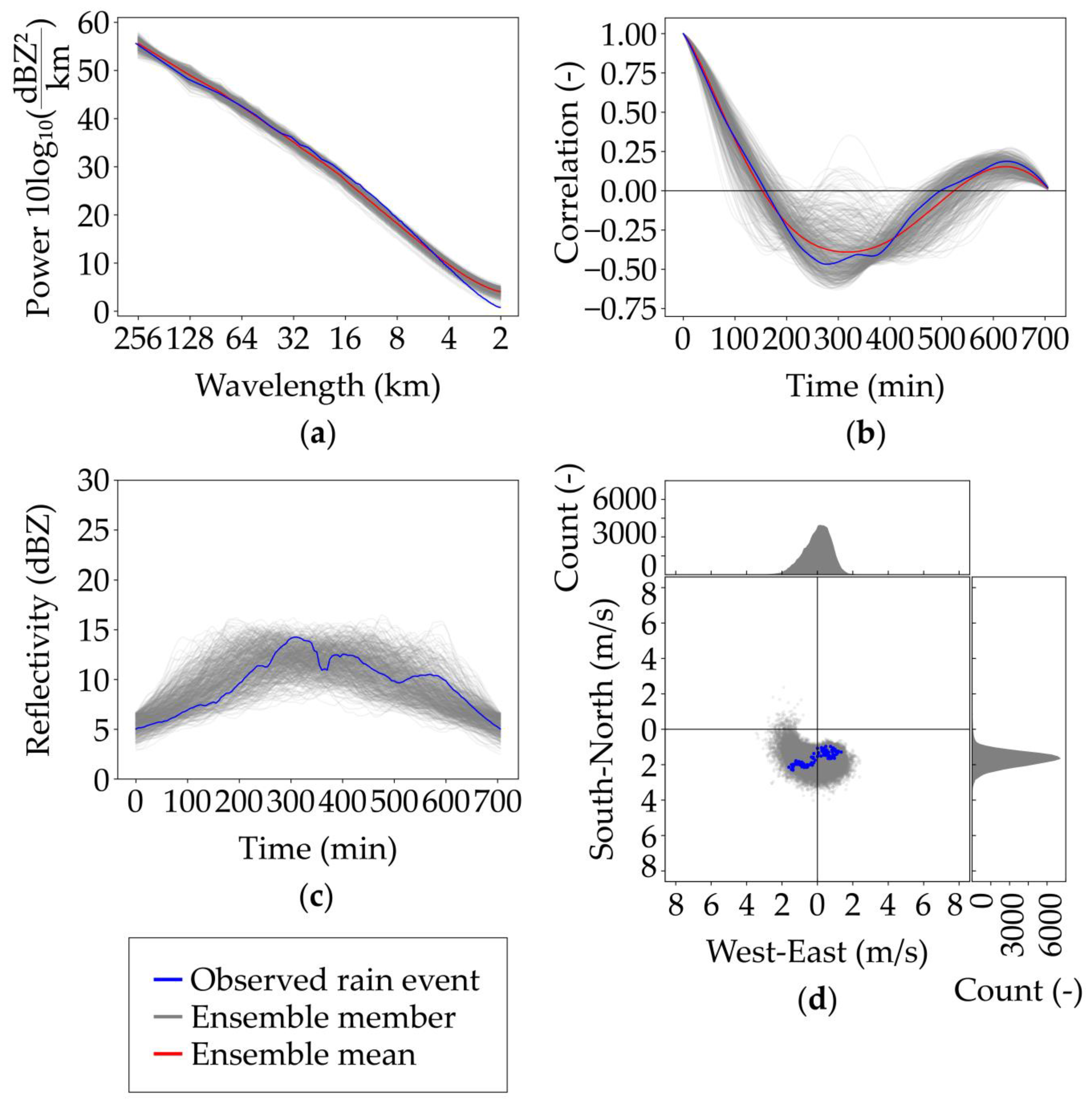
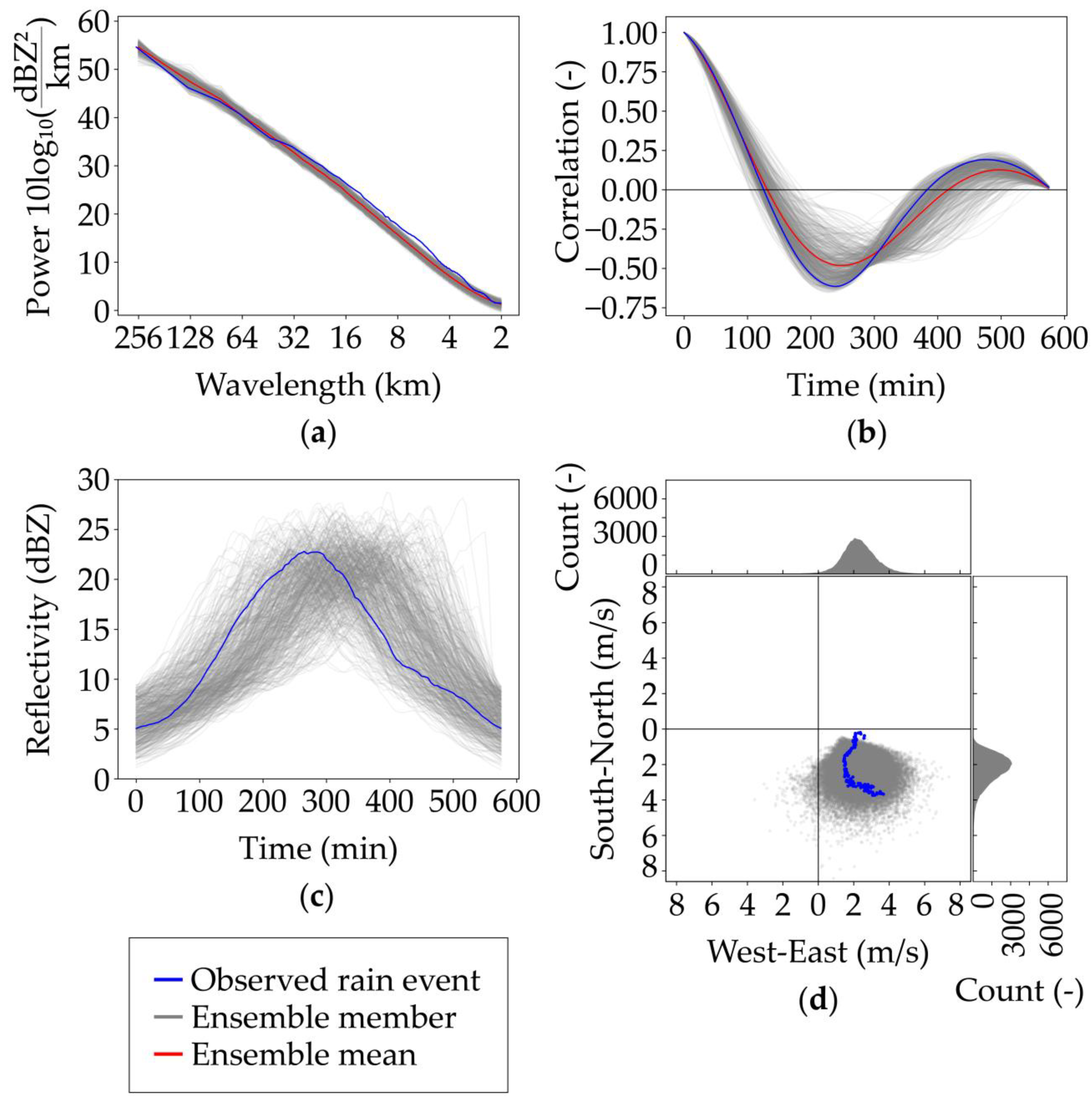
Performance of the rainfall simulation model was evaluated for events 1 (Figure 3) and 2 (Figure 4) by comparing ensemble mean radially averaged spatial power spectra (Figure 3a and Figure 4a), mean areal rainfall (Figure 3b,c and Figure 4b,c), and advection velocities (Figure 3d and Figure 4d) between the observed and simulated rain fields.
The model closely reproduces spatial scaling properties of the two studied rain events, as demonstrated by the close fit between the power spectra for observed and simulated rain fields (Figure 3a and Figure 4a). The quality of the broken line model performance was evaluated by comparing temporal autocorrelation functions between observed and simulated field mean rainfalls (Figure 3b and Figure 4b) and the generated field mean rainfall time series over the entire 256 × 256 km2 field (Figure 3c and Figure 4c). For both studied events, the generated ensemble average temporal autocorrelation function closely followed the observed autocorrelation for lags up to ca. 150 min. The model was capable of reproducing the triangular shape of the event field mean intensity, and the peak intensities of the observed events were on par with the peaks of the simulated ensemble members (Figure 3c and Figure 4c). The negative autocorrelations for longer lags (Figure 3b and Figure 4b) indicate the typical pattern in storm events as increase in rainfall in the rising limb of the hyetograph is matched with a decreasing rainfall intensity in the residing limb when the lag time is long enough.
Figure 3d and Figure 4d present field velocities of rainfall fields during every timestep for all ensemble members and for the observed event. The first event, which has a lower WAR but a higher cumulative areal rainfall, moves to the southern direction, while the second event moves to the southeastern direction with higher velocities and a more widespread velocity distribution. The model showed skill in producing advection velocities resembling those identified for the observed events (Figure 3d and Figure 4d). As expected, the range of variability across the ensemble with 500 realizations is considerably higher than that in the single measured event. Frequency distributions of advection velocities are also illustrated in the marginal plots (Figure 3d and Figure 4d).
Furthermore, model performance was qualitatively evaluated by accumulating rain fields of both observed events and eight randomly selected ensemble members over the entire event duration. Calculated accumulation maps are presented in the Supplementary Materials (Figures S1 and S2). Figure S1, indicating event 1, suggests that ensemble members have more uniform rainfall accumulation patterns compared to the observed event. In Figure S2, representing event 2, the accumulation fields of ensemble members are visually closer to the observed event. However, for both events, the model was considered to give visually satisfactory results and to be able to sufficiently replicate the observed accumulations.

3.2. Ensemble Variation of Cumulative Areal Rainfall across Spatial Scales

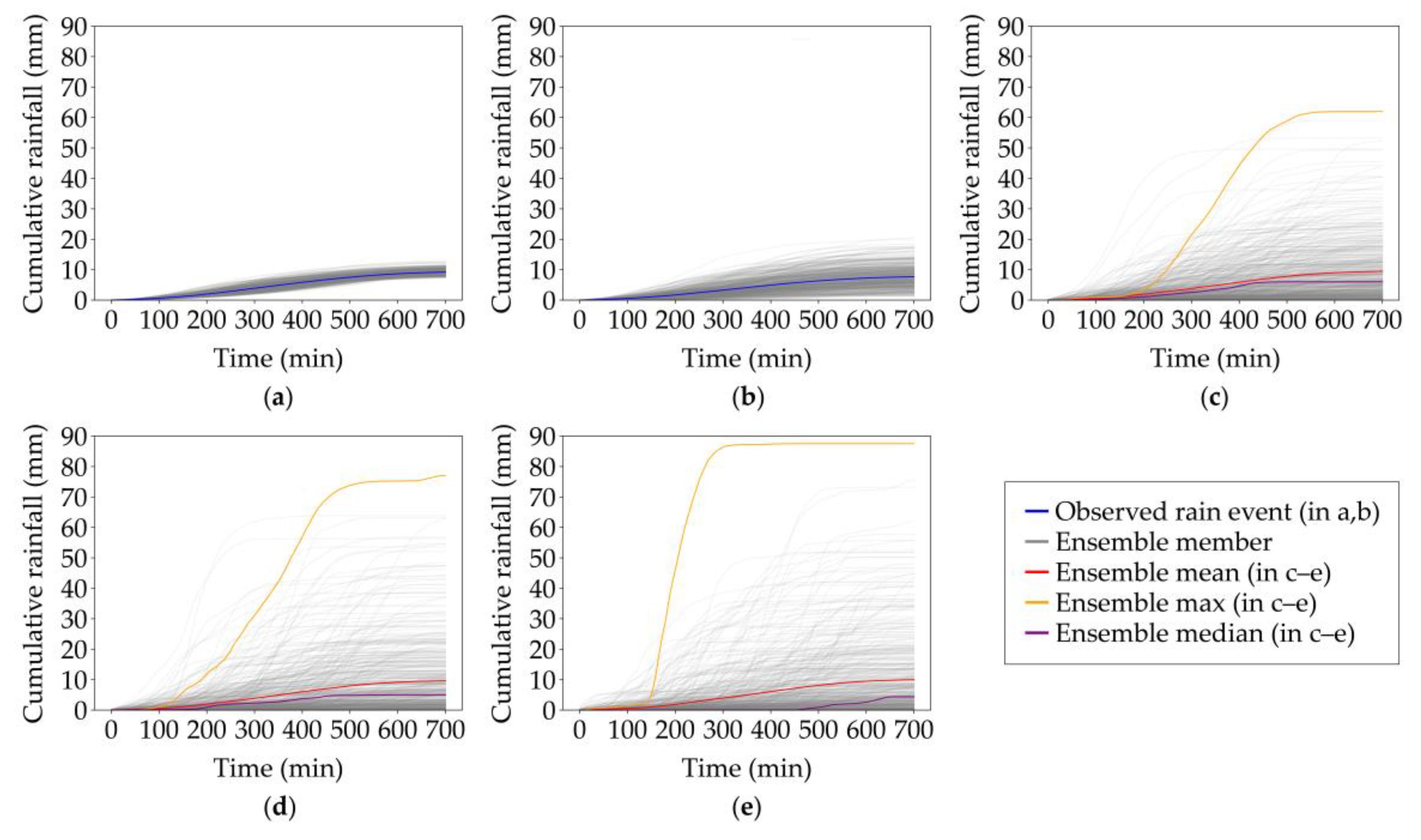
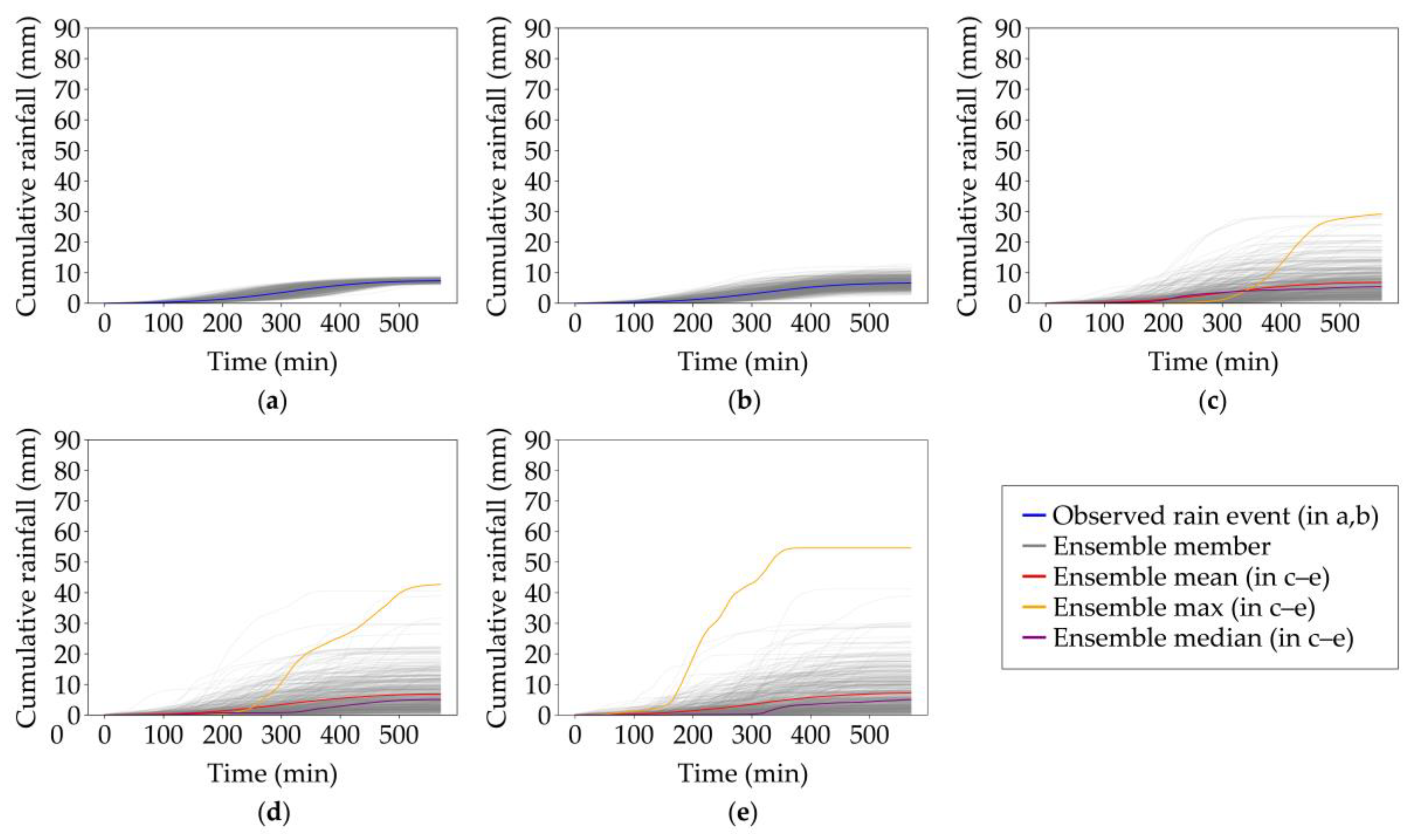
Ensembles of rainfall events were studied in different spatial scales in terms of spatially averaged cumulative rainfall for the entire radar field, the entire Kokemäenjoki river basin, and selected subbasins at three delineation levels (Figure 1, Section 2.5). Table 2 summarizes the statistics of rainfall ensembles for the two events. The standard deviation (std) and the coefficient of variation (CV) increase when moving from larger spatial scales towards smaller scales, which, as expected, indicates an increase in the variability between ensemble members with decreasing spatial domain. This effect is even more pronounced when exploring the spread (maximum–minimum) of cumulative areal rainfall between individual ensemble members. The spread increases from 5.86 mm (entire radar field) to 87.53 mm (3rd-level) in event 1, and from 2.83 mm to 54.60 mm in event 2 (Table 2).
While the cumulative areal rainfall over the event duration is nearly identical between the ensemble members at a large scale (Figure 5a,b and Figure 6a,b), in smaller spatial scales, large differences can be seen depending on whether high-intensity rainfall hits the area or misses it completely (Figure 5c–e and Figure 6c–e). The impact of the likelihood of rain on the spread of event accumulations is clearly seen when comparing event 1 (Figure 5c–e) to event 2 (Figure 6c–e). Event 1 has a lower WAR value (Table 1), which indicates larger areas of no rain, and higher rainfall intensities in the rainy regions. This translates in small-scale basins into a higher spread between ensemble members in event 1 than in event 2. In event 1, individual members are more inclined to produce either negligible or high rainfall when compared to event 2 where the rainfall coverage is more widespread across the simulation domain.
Figure 7 depicts the time series of spatially averaged cumulative rainfalls for all 494 3rd-delineation-level subbasins for both observed rain events. While Figure 5e and Figure 6e show the variation between 500 simulated ensemble members in a selected 3rd-level catchment, and Figure 7 shows the variation between all 494 3rd-level catchments for the observed event, in essence, they describe the same phenomenon, and the variation between the figures should be comparable. Both ensemble member variation for one subbasin (Figure 5e and Figure 6e) and inter-subbasin variation for one event portray the probability of rainfall occurring at a given location when statistics characterizing the storm remain the same. This comparison provides one more test for evaluating the model skill. While the spread is surprisingly similar for event 1 (Figure 5e and Figure 7a), the model drastically underestimates the variation for event 2 (Figure 6e and Figure 7b). It seems that for widespread rain, as in event 2 with a high WAR value, the model has a tendency to produce too-high local rainfall intensities.

3.3. Variability in Total Event Rainfalls between Areal and Gauge Estimates

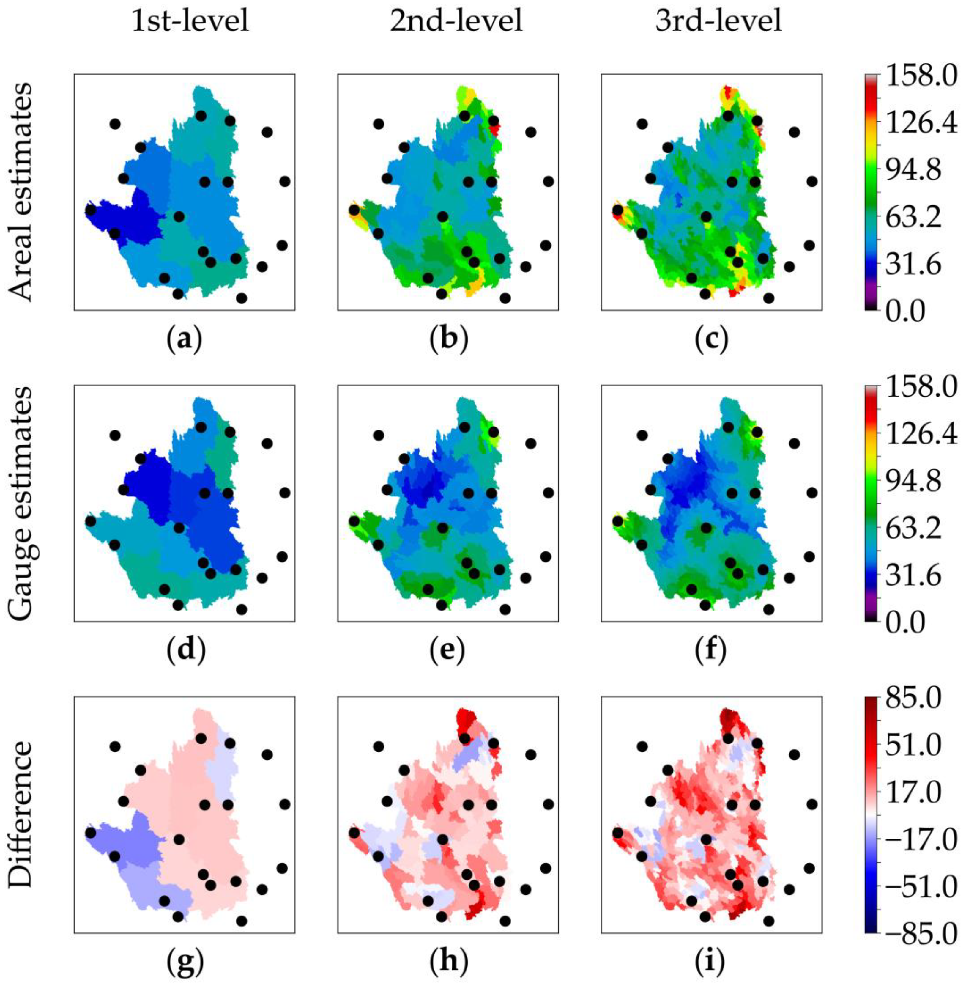
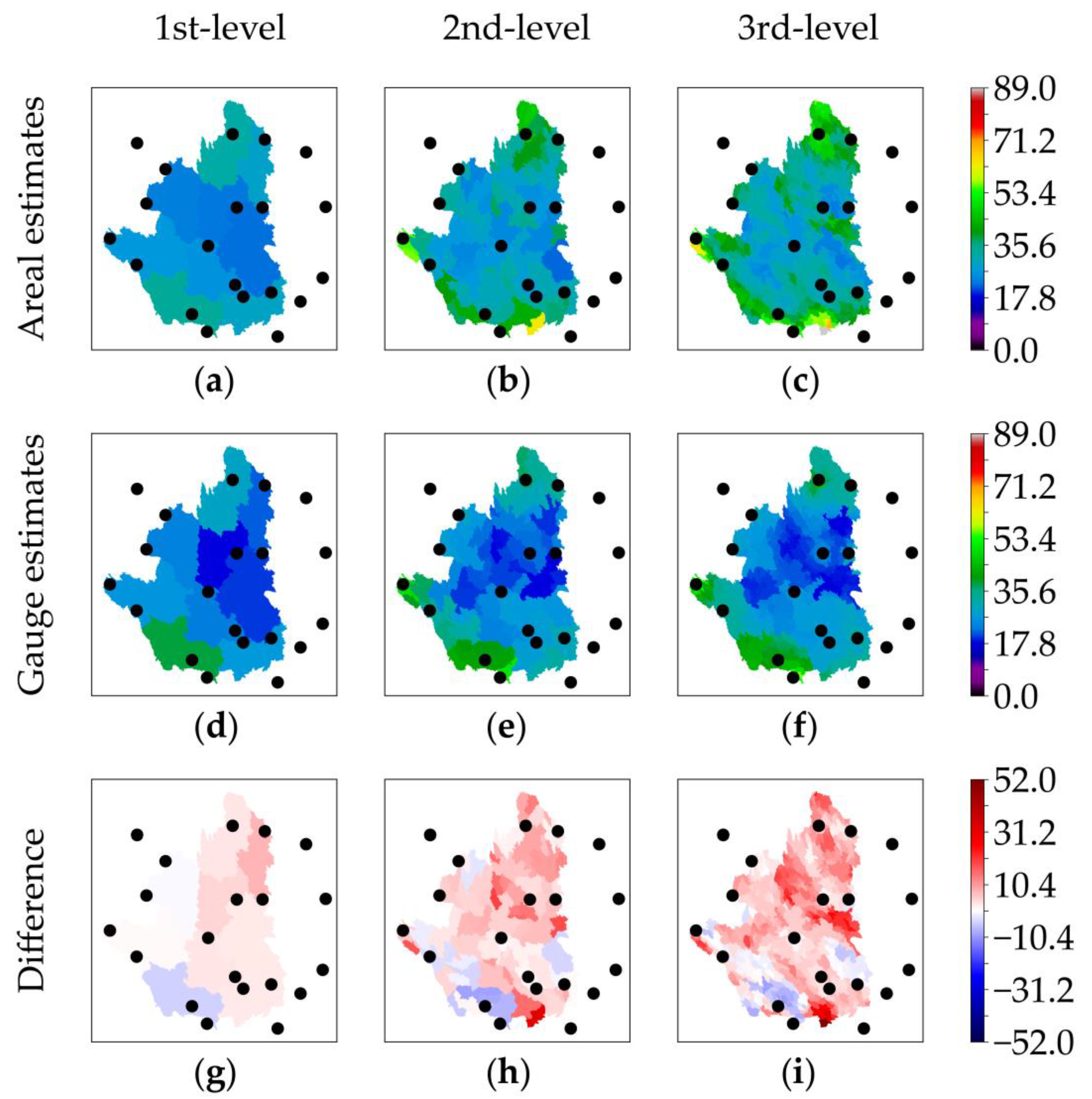
Differences between total event rainfalls (Rtot) calculated either as areal estimates over the area of interest using all pixel values or as gauge estimates calculated only using values from pixels residing at the three closest gauge locations to the area of interest (Section 2.6) were studied. From the hydrological point of view, rarely occurring high-intensity rainfalls are of particular interest. Hence, the ensemble maximum Rtot was calculated as the largest Rtot of all ensemble members for each subbasin, and the impact of the sampling method was evaluated (Figure 8 and Figure 9, Table 3).
Figure 8 and Figure 9 clearly indicate that for smaller subbasins, using only the three closest gauge locations (gauge estimate) in computing the ensemble maximum Rtot can result in clear deviations as compared to utilizing rainfall values from all pixels (areal estimate). This is explained by the relatively sparse gauge network that can completely miss small but intensive rainfall structures in small subbasins, or alternatively can include rainfall from a distant gauge at times of no rain within the subbasin. Similar to the results in cumulative areal rainfall estimates (Section 4.2), event 1 with a lower WAR value produces more pronounced discrepancies than event 2, when changing the sampling method from the areal estimate to the gauge estimate. The deviations in Rtot between the larger basins are smaller due to spatial averaging.
Figure 8h,i and Figure 9h,i show that the ensemble maximum Rtot in different spatial scales is almost always lower for gauge estimates than for areal estimates. The difference increases towards smaller subbasins.
The variability in ensemble maximum Rtot in terms of CV remains relatively stable between the subbasin scales (Table 3). However, std increases significantly when moving into smaller spatial scales from the 1st-level subbasins. In event 1 (event 2), the std of ensemble maximum Rtot calculated from areal estimates doubles from 9.19 (3.86) to 20.90 (7.11) mm between the two lowest spatial scales (the 1st- and 2nd-level subbasins). The increase in gauge estimates is similar but ca. 60% lower, from 10.93 (5.66) to 15.72 (7.01) mm. The increase in the std between the two highest spatial scales (the 2nd- and 3rd-level subbasins) is much lower for both calculation methods.
The highest ensemble maximum Rtot values strongly increase when moving from lower (1st) to higher (3rd) spatial scales (Table 3). The increase is more pronounced for the areal estimates than for the gauge estimates. In the former case, the increase is from 61.98 (33.47) to 157.09 (88.94) mm in event 1 (event 2), and in the latter case, it is from 63.31 (38.24) to 119.46 (58.55) mm. A similar pattern can be seen in the areal mean of ensemble maximum Rtot, which increases from 48.24 (27.10) to 72.97 (35.15) mm in event 1 (event 2) using the areal estimate and from 47.12 (25.24) to 55.46 (28.11) mm in event 1 (event 2) using the gauge estimate. The mean increases more when using the areal estimate than when using the gauge estimate. Patterns in median values are similar, but increases are not as large.

4. Discussion

4.1. Benefits of Spatial Rainfall Data and Ensemble Simulations

The area of interest in this study was the large Kokemäenjoki river basin, and substantial differences can be seen in estimating the event rainfall depending on whether areal estimates or gauge estimates are used. In the operational flood forecasting model of the Finnish Environment Institute [41,44,45], the 3rd-level is the discretization scale for the simulation of inflow to the river systems. The differences in the total event rainfall as estimated either from gauge location values or from the complete 2D spatial information (Figure 8 and Figure 9) are most prominent on this scale. The missing spatial information in the gauge estimates oversimplifies the distribution of the rain and easily leads to underestimation, and sometimes to overestimation, of the total event rainfall. The difference between the areal and the gauge estimates is most drastic in subbasins where the distance to gauges is the highest. These results are in line with earlier research, as radar rainfall data have been observed to provide an efficient means to capture and understand the spatial properties and variability of moving storm systems [25,46,47,48,49]. For example, Quirmbach and Schultz [50] suggested the use of radar data as the primary source of precipitation information when the distance between the ground rainfall gauge and the catchment is more than 4 km, or when the density of the gauge network within the catchment is sparse, less than one gauge per 16 km2.
The results in this study indicate that rainfall estimated using only rain gauges may give smaller estimates compared to the areal estimate from weather radars, especially for events where rainfall is intense and sparse, i.e., as in event 1. This can be seen most clearly at higher spatial scales in Figure 8 and Figure 9 and Table 3. Ensemble maximum values of total event rainfalls are consistently lower when using the gauge estimate than when using the areal estimate. Similarly, Sun et al. [51] found that rain gauges tend to underestimate the average rainfall over the basin compared to weather radar estimates. Moreover, weather radars enable detecting more rainfall events compared to rain gauges, as the areal coverage is larger [3,52].
Stochastic space–time variability in rainfall–runoff processes is a significant source of uncertainty in hydrological applications [22,49,53,54], and the use of radar rainfall data products as input brings additional uncertainties [55,56]. One way to assess rainfall uncertainties is to implement a spatial rainfall model, parameterize it based on radar data, and simulate an ensemble of possible stochastic events. Here, the main added value of rainfall ensemble simulations was the quantification of storm variability and uncertainty, as each ensemble member represents one potential realization of the rain event, and the rainfall uncertainty can be quantified in terms of variability within the ensemble space [55,57]. The cumulative areal rainfall in Figure 5 and Figure 6 and in Table 2 shows large differences between ensemble members in smaller scales, indicating increasing spatial variability of rainfall with decreasing size of the area. Hence, an ensemble approach where, instead of a single design storm, an ensemble of potential design storms is used forms a basis for hydrological analysis and especially for quantifying the impacts of rarely occurring maximum rainfalls across different scales.

4.2. Skill of the Model

The performance of the rainfall simulation model was evaluated by comparing the observed and modeled spatiotemporal properties of rainfall following the approach of Niemi et al. [25]. Unlike in the work of Niemi et al. [25], field-averaged Eulerian temporal autocorrelation of the instantaneous rain fields was not studied, but instead the simulated mean areal rainfall time series were compared against the observed event. The model was able to reproduce the spatial scaling properties of rainfall by generating ensemble average power spectra matching those of the observed fields (Figure 3a and Figure 4a). The correspondence between the measured and modeled temporal properties of the rainfall event (Figure 3b and Figure 4b) was similar to the results of Niemi et al. [25]. The model also reproduced the temporal pattern and the magnitude of the event field mean rainfall (Figure 3c and Figure 4c). In the case of advection velocities, the model results were within the observed range of velocities, showing a large variability in modeled values extending outside of the velocity pattern of the observed event (Figure 3d and Figure 4d).

4.3. Limitations of the Model

The model has limitations that simplify the evolution of the simulated rainfall fields compared to natural events. Advection between consecutive time steps is modeled using one spatially uniform direction and magnitude in all grid cells. This means that the advection of the entire simulated rain field is independent of location, while in reality, rainfall structures move in different directions with different velocities at the same time.
Smooth advection handling and countering the wrap-around effect of moving fields around the edges of the simulation domain were applied to the model as suggested by Pegram and Clothier [37] as well as Niemi et al. [25]. Rainfall fields with an area of 256 × 256 km2 were clipped from the center of the 512 × 512 km2 simulation domain. The size of the simulation domain was considered to be sufficient for countering the wrap-around effect. However, there were some rare cases where arbitrary rain appeared and accumulated on the edges of the study area. These rare cases can be eliminated by increasing the size of the simulation domain, even though this would increase the simulation time.
The pySTEPS model simulates rain fields with the assumption of isotropy, which is considered to be a reasonable approximation of a rainfall event for most practical needs [25]. However, accounting for the anisotropic nature of the rainfall enables the generation of more realistic rainfall events [25]. In the current study, the rainfall model parameterization was based on measured events, and the implication of the isotropic rainfall field assumption is reflected in the values of the model parameters. The modeled rainfall ensemble did not capture the time of occurrence of the position of the peak field mean rainfall of the observed event (Figure 3c and Figure 4c), which is a known issue with stochastic rainfall models [14]. This, however, is to be expected as the model parameterization did not contain information about the timing of the peak.
The model generates radar reflectivities (dBZ) as its parameterization benefits from the nearly normal distribution of reflectivities. Hydrologists are, however, interested in rainfall intensities (mm/h) or the water column depth of rainfall (mm). The required unit conversion causes challenges because rainfall intensity is zero-bounded, but reflectivity is logarithmic and not bounded. The unit conversion seems to accentuate the ensemble variance in the event total rainfalls in the largest spatial scale (Figure 5a and Figure 6a) where, in theory, there should be no variation between the ensemble members. This variation originates from alternatively adjusting field mean and standard deviation, and WAR, to match the desired values. After the unit conversion, the variation becomes more pronounced.
Currently, the model is also missing the ability to simulate dry periods within the event. Incorporating this ability would enable the simulation of different types of rain events with even more varying intensity patterns. Moreover, spatial rainfall distribution could be improved by taking into account the topography of the study area. For this study, topography was not included because the study area is relatively flat, and topography was consequently considered not to have a significant impact on the results. However, for areas with significant differences in topography, this should be considered.
The stochastic rainfall model as a simplification of a complex natural phenomenon can at its best provide an efficient and parsimonious method to condense information from a very large observed dataset to just a handful of parameter values [14]. If the parameter values can be regionalized to new sites, the model can provide a transparent and efficient way to estimate a range of design values for practical applications. This calls for future examination and provides a natural extension to the current study.

5. Conclusions

Variations in spatiotemporal rainfall intensity are one of the main interests in hydrological modeling and applications because many sectors and functions of society are affected and particularly vulnerable to, e.g., heavy-rainfall-induced flooding.
In this study, a stochastic rainfall model was applied and parameterized against observed rain events utilizing radar rainfall data from 2013 to 2016 for the Kokemäenjoki river basin in Western Finland. Subsequently, the model was applied to generate ensembles of 2D design storms mimicking the spatiotemporal statistics of the observed rain events.
The skill of the model was evaluated by assessing how the model reproduced spatial scaling properties of rainfall, temporal autocorrelation properties of a rainfall event, event field mean rainfalls, and advection velocities. It was found that the model was able to reproduce the properties listed above.
An ensemble of simulated rainfall events was used to demonstrate how events with a similar large-scale mean areal rainfall can produce drastically different maximum total event rainfalls in smaller scales. In addition, total event rainfalls across different spatial scales were calculated as areal estimates and compared to estimates produced by sampling rainfall only at gauge locations. The sampling method, i.e., areal vs. gauge estimates, was shown to affect the maximum total event rainfall estimates.
The results demonstrate the benefits of using spatially distributed 2D design rainfall ensembles as opposed to a single-point-scale design rainfall event. The main added value they provide is the quantification of variability and uncertainty within even a single event, let alone between multiple events with varying characteristics. Understanding the range of variation is important in decision-making processes when planning climate-resilient and adaptive solutions in different sectors of society.

Supplementary Materials

The following supporting information is provided at https://www.mdpi.com/article/10.3390/w15173066/s1, Figure S1: Event 1 total event rainfall (mm) of the entire 256 × 256 km2 radar field for (a) observed rain event and (bi) eight randomly selected ensemble members; Figure S2: Event 2 total event rainfall (mm) of the entire 256 × 256 km2 radar field for (a) observed rain event and (bi) eight randomly selected ensemble members; Table S1: Parameters for modeling mean areal rainfall (μ), advection magnitude (Vmag), and advection direction (Vdir) time series [35]; Table S2: Parameters for modeling field standard deviation (σ) [40] and wetted area ratio (WAR) [25] as quadratic functions of mean areal rainfall (μ); Table S3: Parameters for modeling spectral slopes (β1 and β2) for power-law filter as quadratic functions of mean areal rainfall (μ) [40]; Table S4: Parameters for modeling mean lag-1 and mean lag-2 Lagrangian temporal autocorrelations (ρ1,k and ρ2,k) [40]. References [25,35,40] are cited in the Supplementary Materials.

Author Contributions

Conceptualization, V.L., T.N., T.K. and H.K.; methodology, V.L., T.N. and T.K.; software, V.L., T.N. and T.K.; validation, V.L., T.N. and T.K.; formal analysis, V.L.; investigation, V.L., T.N. and T.K.; resources, T.K. and H.K.; data curation, V.L., T.N. and T.K.; writing—original draft preparation, V.L.; writing—review and editing, V.L., T.N., T.K. and H.K.; visualization, V.L.; supervision, T.K. and H.K.; project administration, V.L., T.K. and H.K.; funding acquisition, V.L. and H.K. All authors have read and agreed to the published version of the manuscript.

Funding

Ville Lindgren received funding from Maa-ja vesitekniikan tuki ry., grant number 32230; Aalto University, grant number 913672; and Sven Hallinin tutkimussäätiö sr.

Data Availability Statement

Radar precipitation observations used in this study were provided by the Finnish Meteorological Institute. The Optimal Rain Products with Dual-Pol Doppler Weather Radar (OSAPOL) project was funded by the European Regional Development Fund and the Finnish Funding Agency for Technology and Innovation (Tekes) (grant number 4459/31/2014). OSAPOL data are not publicly available. River basin data were retrieved from the open information service of the Finnish Environment Institute (Syke) [27] and locations of gauge stations measuring hourly rainfall [43] as well as rainfall intensity data for those gauges [29] were obtained from the Finnish Meteorological Institute’s open research data service.

Acknowledgments

We thank Seppo Pulkkinen from the Finnish Meteorological Institute for providing OSAPOL radar rainfall data and helping with pySTEPS.

Conflicts of Interest

The authors declare no conflict of interest. The funders had no role in the design of the study; in the collection, analyses, or interpretation of data; in the writing of the manuscript; or in the decision to publish the results.

References

  1. Notaro, V.; Fontanazza, C.M.; Freni, G.; Puleo, V. Impact of Rainfall Data Resolution in Time and Space on the Urban Flooding Evaluation. Water Sci. Technol. 2013, 68, 1984–1993. [Google Scholar] [CrossRef]
  2. Niemi, T.J.; Warsta, L.; Taka, M.; Hickman, B.; Pulkkinen, S.; Krebs, G.; Moisseev, D.N.; Koivusalo, H.; Kokkonen, T. Applicability of Open Rainfall Data to Event-Scale Urban Rainfall-Runoff Modelling. J. Hydrol. 2017, 547, 143–155. [Google Scholar] [CrossRef]
  3. Wright, D.B.; Smith, J.A.; Villarini, G.; Baeck, M. Applications of Radar-Based Rainfall Estimates to Urban Flood Studies. J. Water Manag. Model. 2013. [Google Scholar] [CrossRef]
  4. Thorndahl, S.; Einfalt, T.; Willems, P.; Nielsen, J.E.; ten Veldhuis, M.-C.; Arnbjerg-Nielsen, K.; Rasmussen, M.R.; Molnar, P. Weather Radar Rainfall Data in Urban Hydrology. Hydrol. Earth Syst. Sci. 2017, 21, 1359–1380. [Google Scholar] [CrossRef]
  5. Peura, M. Anomaly Detection and Removal in Radar Images (AnDRe)—Final Project Report; Finnish Meteorological Institute: Helsinki, Finland, 2002. [Google Scholar]
  6. Giangrande, S.E.; Ryzhkov, A.V. Estimation of Rainfall Based on the Results of Polarimetric Echo Classification. J. Appl. Meteorol. Climatol. 2008, 47, 2445–2462. [Google Scholar] [CrossRef]
  7. Mäkinen, T.; Ritvanen, J.; Pulkkinen, S.; Weisshaupt, N.; Koistinen, J. Bayesian Classification of Nonmeteorological Targets in Polarimetric Doppler Radar Measurements. J. Atmos. Ocean. Technol. 2022, 39, 1561–1578. [Google Scholar] [CrossRef]
  8. Bruni, G.; Reinoso, R.; van de Giesen, N.C.; Clemens, F.H.L.R.; ten Veldhuis, J.A.E. On the Sensitivity of Urban Hydrodynamic Modelling to Rainfall Spatial and Temporal Resolution. Hydrol. Earth Syst. Sci. 2015, 19, 691–709. [Google Scholar] [CrossRef]
  9. Bowler, N.E.; Pierce, C.E.; Seed, A.W. STEPS: A Probabilistic Precipitation Forecasting Scheme Which Merges an Extrapolation Nowcast with Downscaled NWP. Q. J. R. Meteorol. Soc. 2006, 132, 2127–2155. [Google Scholar] [CrossRef]
  10. Paschalis, A.; Molnar, P.; Fatichi, S.; Burlando, P. A Stochastic Model for High-Resolution Space-Time Precipitation Simulation. Water Resour. Res. 2013, 49, 8400–8417. [Google Scholar] [CrossRef]
  11. Peleg, N.; Fatichi, S.; Paschalis, A.; Molnar, P.; Burlando, P. An Advanced Stochastic Weather Generator for Simulating 2-D High-Resolution Climate Variables. J. Adv. Model. Earth Syst. 2017, 9, 1595–1627. [Google Scholar] [CrossRef]
  12. Singer, M.B.; Michaelides, K.; Hobley, D.E.J. STORM 1.0: A Simple, Flexible, and Parsimonious Stochastic Rainfall Generator for Simulating Climate and Climate Change. Geosci. Model Dev. 2018, 11, 3713–3726. [Google Scholar] [CrossRef]
  13. Niemi, T.J.; Kokkonen, T.; Seed, A.W. A Simple and Effective Method for Quantifying Spatial Anisotropy of Time Series of Precipitation Fields. Water Resour. Res. 2014, 50, 5906–5925. [Google Scholar] [CrossRef]
  14. Cortis, A.; Puente, C.E.; Sivakumar, B. Encoding Hydrologic Information via a Fractal Geometric Approach and Its Extensions. Stoch. Environ. Res. Risk Assess. 2010, 24, 625–632. [Google Scholar] [CrossRef]
  15. Marsalek, J.; Watt, W.E. Design Storms for Urban Drainage Design. Can. J. Civ. Eng. 1984, 11, 574–584. [Google Scholar] [CrossRef]
  16. Berk, M.; Špačková, O.; Straub, D. Probabilistic Design Storm Method for Improved Flood Estimation in Ungauged Catchments. Water Resour. Res. 2017, 53, 10701–10722. [Google Scholar] [CrossRef]
  17. Onof, C.; Chandler, R.E.; Kakou, A.; Northrop, P.; Wheater, H.S.; Isham, V. Rainfall Modelling Using Poisson-Cluster Processes: A Review of Developments. Stoch. Environ. Res. Risk Assess. 2000, 14, 384–411. [Google Scholar] [CrossRef]
  18. Cazanescu, S.; Cazanescu, R.A. New Hydrological Approach for Environmental Protection and Floods Management. Bull. Univ. Agric. Sci. Vet. Med. Cluj-Napoca. Agric. 2009, 66, 63–70. [Google Scholar] [CrossRef]
  19. Chimene, C.A.; Campos, J.N.B. The Design Flood under Two Approaches: Synthetic Storm Hyetograph and Observed Storm Hyetograph. J. Appl. Water Eng. Res. 2020, 8, 171–182. [Google Scholar] [CrossRef]
  20. Overeem, A.; Holleman, I.; Buishand, A. Derivation of a 10-Year Radar-Based Climatology of Rainfall. J. Appl. Meteorol. Climatol. 2009, 48, 1448–1463. [Google Scholar] [CrossRef]
  21. Segond, M.-L.; Wheater, H.S.; Onof, C. The Significance of Spatial Rainfall Representation for Flood Runoff Estimation: A Numerical Evaluation Based on the Lee Catchment, UK. J. Hydrol. 2007, 347, 116–131. [Google Scholar] [CrossRef]
  22. Peleg, N.; Blumensaat, F.; Molnar, P.; Fatichi, S.; Burlando, P. Partitioning the Impacts of Spatial and Climatological Rainfall Variability in Urban Drainage Modeling. Hydrol. Earth Syst. Sci. 2017, 21, 1559–1572. [Google Scholar] [CrossRef]
  23. PySteps Developers. Pysteps Reference, Release 1.5.1; 2021. Available online: https://pysteps.readthedocs.io/_/downloads/en/v1.5.1/pdf/ (accessed on 25 August 2023).
  24. Pulkkinen, S.; Nerini, D.; Pérez Hortal, A.A.; Velasco-Forero, C.; Seed, A.; Germann, U.; Foresti, L. Pysteps: An Open-Source Python Library for Probabilistic Precipitation Nowcasting (v1.0). Geosci. Model Dev. 2019, 12, 4185–4219. [Google Scholar] [CrossRef]
  25. Niemi, T.J.; Guillaume, J.H.A.; Kokkonen, T.; Hoang, T.M.T.; Seed, A.W. Role of Spatial Anisotropy in Design Storm Generation: Experiment and Interpretation. Water Resour. Res. 2016, 52, 69–89. [Google Scholar] [CrossRef]
  26. Ekholm, M. Suomen Vesistöalueet. In Vesi-ja Ympäristöhallinnon Julkaisuja—Sarja A 126; Vesi-ja Ympäristöhallitus: Helsinki, Finland, 1993; ISBN 951-37-1087-4. [Google Scholar]
  27. Finnish Environment Institute Catchment Areas. Available online: https://ckan.ymparisto.fi/dataset/%7B44394B13-85D7-4998-BD06-8ADC77C7455C%7D (accessed on 27 August 2022).
  28. Schleiss, M.; Olsson, J.; Berg, P.; Niemi, T.; Kokkonen, T.; Thorndahl, S.; Nielsen, R.; Ellerbæk Nielsen, J.; Bozhinova, D.; Pulkkinen, S. The Accuracy of Weather Radar in Heavy Rain: A Comparative Study for Denmark, the Netherlands, Finland and Sweden. Hydrol. Earth Syst. Sci. 2020, 24, 3157–3188. [Google Scholar] [CrossRef]
  29. Finnish Meteorological Institute. Download Observations. Available online: https://en.ilmatieteenlaitos.fi/download-observations (accessed on 17 August 2023).
  30. Finnish Meteorological Institute. Precipitation Return Levels in Finland. Available online: https://www.climateguide.fi/articles/precipitation-return-levels-in-finland/ (accessed on 17 August 2023).
  31. Marshall, J.S.; Palmer, W.M.K. The Distribution of Raindrops with Size. J. Atmos. Sci. 1948, 5, 165–166. [Google Scholar] [CrossRef]
  32. Leinonen, J.; Moisseev, D.; Leskinen, M.; Petersen, W.A. A Climatology of Disdrometer Measurements of Rainfall in Finland over Five Years with Implications for Global Radar Observations. J. Appl. Meteorol. Climatol. 2012, 51, 392–404. [Google Scholar] [CrossRef]
  33. Seed, A.W.; Srikanthan, R.; Menabde, M. A Space and Time Model for Design Storm Rainfall. J. Geophys. Res. Atmos. 1999, 104, 31623–31630. [Google Scholar] [CrossRef]
  34. Seed, A. Modelling and Forecasting Rainfall in Space and Time. In Scales in Hydrology and Water Management; Tchiguirinskaia, I., Hubert, P., Bonell, M., Eds.; IAHS Publication: Wallingford, UK, 2004; pp. 137–152. ISBN 1901502627. [Google Scholar]
  35. Seed, A.W.; Draper, C.; Srikanthan, R.; Menabde, M. A Multiplicative Broken-Line Model for Time Series of Mean Areal Rainfall. Water Resour. Res. 2000, 36, 2395–2399. [Google Scholar] [CrossRef]
  36. Venugopal, V.; Foufoula-Georgiou, E.; Sapozhnikov, V. Evidence of Dynamic Scaling in Space-Time Rainfall. J. Geophys. Res. Atmos. 1999, 104, 31599–31610. [Google Scholar] [CrossRef]
  37. Pegram, G.G.S.; Clothier, A.N. High Resolution Space–Time Modelling of Rainfall: The “String of Beads” Model. J. Hydrol. 2001, 241, 26–41. [Google Scholar] [CrossRef]
  38. Waldvogel, A.; Federer, B.; Grimm, P. Criteria for the Detection of Hail Cells. J. Appl. Meteorol. Climatol. 1979, 18, 1521–1525. [Google Scholar] [CrossRef]
  39. Saltikoff, E.; Tuovinen, J.P.; Kotro, J.; Kuitunen, T.; Hohti, H. A Climatological Comparison of Radar and Ground Observations of Hail in Finland. J. Appl. Meteorol. Climatol. 2010, 49, 101–114. [Google Scholar] [CrossRef]
  40. Seed, A.; Jordan, P.; Pierce, C.; Leonard, M.; Nathan, R.; Kordomenidi, E. Stochastic Simulation of Space-Time Rainfall Patterns for the Brisbane River Catchment. In Hydrology and Water Resources Symposium 2014; Engineers Australia: Barton, ACT, Australia, 2014; pp. 1026–1039. ISBN 9781922107190. [Google Scholar]
  41. Olsson, T.; Jakkila, J.; Veijalainen, N.; Backman, L.; Kaurola, J.; Vehviläinen, B. Impacts of Climate Change on Temperature, Precipitation and Hydrology in Finland—Studies Using Bias Corrected Regional Climate Model Data. Hydrol. Earth Syst. Sci. Discuss. 2015, 12, 2657–2706. [Google Scholar] [CrossRef]
  42. Lindgren, V.; Guillaume, J.H.A.; Räsänen, T.A.; Jakkila, J.; Veijalainen, N.; Kummu, M. Spatiotemporal Hydroclimate Variability in Finland: Past Trends. J. Hydrometeorol. 2017, 18, 1765–1782. [Google Scholar] [CrossRef]
  43. Finnish Meteorological Institute Observation Stations. Available online: https://www.ilmatieteenlaitos.fi/havaintoasemat (accessed on 27 August 2022).
  44. Vehviläinen, B.; Huttunen, M.; Huttunen, I. Hydrological Forecasting and Real Time Monitoring in Finland: The Watershed Simulation and Forecasting System (WSFS). In Proceedings of the Innovation, Advances and Implementation of Flood Forecasting Technology, Tromsø, Norway, 17–19 October 2005; p. 10. [Google Scholar]
  45. Veijalainen, N. Estimation of Climate Change Impacts on Hydrology and Floods in Finland; Aalto University: Helsinki, Finland, 2012. [Google Scholar]
  46. Paschalis, A.; Fatichi, S.; Molnar, P.; Rimkus, S.; Burlando, P. On the Effects of Small Scale Space–Time Variability of Rainfall on Basin Flood Response. J. Hydrol. 2014, 514, 313–327. [Google Scholar] [CrossRef]
  47. Belachsen, I.; Marra, F.; Peleg, N.; Morin, E. Convective Rainfall in a Dry Climate: Relations with Synoptic Systems and Flash-Flood Generation in the Dead Sea Region. Hydrol. Earth Syst. Sci. 2017, 21, 5165–5180. [Google Scholar] [CrossRef]
  48. Peleg, N.; Skinner, C.; Fatichi, S.; Molnar, P. Temperature Effects on the Spatial Structure of Heavy Rainfall Modify Catchment Hydro-Morphological Response. Earth Surf. Dyn. 2020, 8, 17–36. [Google Scholar] [CrossRef]
  49. Peleg, N.; Ban, N.; Gibson, M.J.; Chen, A.S.; Paschalis, A.; Burlando, P.; Leitão, J.P. Mapping Storm Spatial Profiles for Flood Impact Assessments. Adv. Water Resour. 2022, 166, 104258. [Google Scholar] [CrossRef]
  50. Quirmbach, M.; Schultz, G.A. Comparison of Rain Gauge and Radar Data as Input to an Urban Rainfall-Runoff Model. Water Sci. Technol. 2002, 45, 27–33. [Google Scholar] [CrossRef]
  51. Sun, X.; Mein, R.G.; Keenan, T.D.; Elliott, J.F. Flood Estimation Using Radar and Raingauge Data. J. Hydrol. 2000, 239, 4–18. [Google Scholar] [CrossRef]
  52. Lengfeld, K.; Kirstetter, P.E.; Fowler, H.J.; Yu, J.; Becker, A.; Flamig, Z.; Gourley, J. Use of Radar Data for Characterizing Extreme Precipitation at Fine Scales and Short Durations. Environ. Res. Lett. 2020, 15, 085003. [Google Scholar] [CrossRef]
  53. Fatichi, S.; Ivanov, V.Y.; Paschalis, A.; Peleg, N.; Molnar, P.; Rimkus, S.; Kim, J.; Burlando, P.; Caporali, E. Uncertainty Partition Challenges the Predictability of Vital Details of Climate Change. Earth’s Futur. 2016, 4, 240–251. [Google Scholar] [CrossRef]
  54. Moraga, J.S.; Peleg, N.; Fatichi, S.; Molnar, P.; Burlando, P. Revealing the Impacts of Climate Change on Mountainous Catchments through High-Resolution Modelling. J. Hydrol. 2021, 603, 126806. [Google Scholar] [CrossRef]
  55. AghaKouchak, A.; Habib, E.; Bárdossy, A. Modeling Radar Rainfall Estimation Uncertainties: Random Error Model. J. Hydrol. Eng. 2009, 15, 265–274. [Google Scholar] [CrossRef]
  56. Ochoa-Rodriguez, S.; Wang, L.P.; Willems, P.; Onof, C. A Review of Radar-Rain Gauge Data Merging Methods and Their Potential for Urban Hydrological Applications. Water Resour. Res. 2019, 55, 6356–6391. [Google Scholar] [CrossRef]
  57. Hartke, S.H.; Wright, D.B.; Li, Z.; Maggioni, V.; Kirschbaum, D.B.; Khan, S. Ensemble Representation of Satellite Precipitation Uncertainty Using a Nonstationary, Anisotropic Autocorrelation Model. Water Resour. Res. 2022, 58, e2021WR031650. [Google Scholar] [CrossRef]
Figure 1. (a) Location of the Kokemäenjoki river basin (light blue area) and the radar network (green circles with a 120 km radius); (b) 3rd-delineation-level subbasins within the study area (light blue), as well as selected 1st (yellow)-, 2nd (orange)-, and 3rd (red)-level subbasins. Rainfall gauge network (dark blue circles) is also shown.
Water 15 03066 g001
Figure 2. Flowchart illustrating the modeling process [24,25,28,35,36,37,38,39,40].
Water 15 03066 g002
Figure 3. Model performance for event 1. (a) Ensemble average radially averaged 1D spatial power spectra; (b) temporal autocorrelation functions of the mean areal rainfall; (c) mean areal rainfall broken line time series; (d) advection velocities to southern and eastern directions with marginal plots presenting ensemble distribution. Observed event is illustrated with blue, simulated ensemble members with gray, and ensemble average with red color.
Water 15 03066 g003
Figure 4. Model performance for event 2. (a) Ensemble average radially averaged 1D spatial power spectra; (b) temporal autocorrelation functions of the mean areal rainfall; (c) mean areal rainfall broken line time series; (d) advection velocities to southern and eastern directions with marginal plots presenting ensemble distribution. Observed event is illustrated with blue, simulated ensemble members with gray, and ensemble average with red color.
Water 15 03066 g004
Figure 5. Event 1 cumulative areal rainfall (mm) time series for (a) the entire radar field, (b) the entire Kokemäenjoki river basin, (c) the selected 1st-delineation-level subbasin, (d) the selected 2nd-delineation-level subbasin, and (e) the selected 3rd-delineation-level subbasin. Observed event is illustrated with blue (a,b), simulated ensemble members with gray (ae), realization with ensemble mean cumulative areal rainfall with red (ce), realization with ensemble maximum cumulative areal rainfall with orange (ce), and realization with ensemble median cumulative areal rainfall with yellow color (ce).
Water 15 03066 g005
Figure 6. Event 2 cumulative areal rainfall (mm) time series for (a) the entire radar field, (b) the entire Kokemäenjoki river basin, (c) the selected 1st-delineation-level subbasin; (d) the selected 2nd-delineation-level subbasin; (e) the selected 3rd-delineation-level subbasin. Observed event is illustrated with blue (a,b), simulated ensemble members with gray (ae), realization with ensemble mean cumulative areal rainfall with red (ce), realization with ensemble maximum cumulative areal rainfall with orange (ce), and realization with ensemble median cumulative areal rainfall with yellow color (ce).
Water 15 03066 g006
Figure 7. Cumulative areal rainfall (mm) time series of each 3rd-delineation-level subbasin for (a) event 1 and (b) event 2. 3rd-level subbasins are illustrated with gray, subbasin mean cumulative areal rainfall with red, subbasin with maximum cumulative areal rainfall with orange, and subbasin with median cumulative areal rainfall with yellow color.
Water 15 03066 g007
Figure 8. Event 1 ensemble maximum of total event rainfall (mm) utilizing areal estimates for (a) 1st-level subbasins, (b) 2nd-level subbasins, and (c) 3rd-level subbasin. Ensemble maximum of total event rainfall (mm) utilizing gauge estimates for (d) 1st-level subbasins, (e) 2nd-level subbasins, and (f) 3rd-level subbasin. The difference (mm) between two calculation methods (areal–gauge) for (g) 1st-level subbasins, (h) 2nd-level subbasins, and (i) 3rd-level subbasin. Gauge locations are denoted with black circles.
Water 15 03066 g008
Figure 9. Event 2 ensemble maximum of total event rainfall (mm) utilizing areal estimates for (a) 1st-level subbasins, (b) 2nd-level subbasins, and (c) 3rd-level subbasin. Ensemble maximum of total event rainfall (mm) utilizing gauge estimates for (d) 1st-level subbasins, (e) 2nd-level subbasins, and (f) 3rd-level subbasin. The difference (mm) between two calculation methods (areal–gauge) for (g) 1st-level subbasins, (h) 2nd-level subbasins, and (i) 3rd-level subbasin. Gauge locations are denoted with black circles.
Water 15 03066 g009
Table 1. Selected rainfall events and their characteristics.
EventStart and End TimeDuration (h:mm)Average (Peak) μ (mm/h)Average (Maximum) WAR (%)Cumulative Mean Areal Rainfall (mm)
Event 127 June 2013, 08:10–
27 June 2013, 19:55
11:451.11 (2.17)30 (49)12.28
Event 228 October 2013, 18:10–
29 October 2013, 03:45
9:350.68 (1.73)55 (91)6.16
Table 2. Statistics of cumulative areal rainfall for event 1 (event 2) at various spatial scales.
Spatial ScaleMax (mm)Min (mm)Mean (mm)Median (mm)Std (mm)CV (-)
Radar field13.05 (8.83)7.19 (6.00)9.22 (7.36)9.06 (7.34)0.99 (0.48)0.11 (0.07)
Kokemäenjoki river basin20.53 (12.67)1.19 (2.73)7.72 (6.62)7.33 (6.42)3.58 (1.73)0.46 (0.26)
1st-level62.00 (29.20)0.02 (0.68)9.50 (6.86)6.02 (5.50)10.20 (5.24)1.07 (0.76)
2nd-level77.09 (42.76)0.01 (0.07)9.65 (6.90)5.03 (5.05)12.39 (6.12)1.28 (0.89)
3rd-level87.53 (54.64)0.00 (0.04)10.01 (7.14)4.39 (5.04)13.39 (6.67)1.34 (0.93)
Table 3. Statistics of ensemble maximum of total event rainfall for event 1 (event 2) utilizing areal and gauge estimates at different spatial scales.
Spatial ScaleStatisticAreal EstimateGauge EstimateDifference
1st-levelMax (mm)61.98 (33.47)63.31 (38.24)−1.33 (−4.77)
1st-levelMean (mm)48.24 (27.10)47.12 (25.24)1.12 (1.86)
1st-levelMedian (mm)47.35 (26.74)47.74 (23.95)−0.39 (2.80)
1st-levelStd (mm)9.19 (3.86)10.93 (5.66)−1.74 (−1.80)
1st-levelCV (-)0.19 (0.14)0.23 (0.22)−0.04 (−0.08)
2nd-levelMax (mm)137.87 (62.89)100.76 (50.10)37.11 (12.79)
2nd-levelMean (mm)68.81 (32.99)54.88 (27.61)13.93 (5.38)
2nd-levelMedian (mm)62.73 (31.51)54.48 (26.61)8.25 (4.90)
2nd-levelStd (mm)20.90 (7.11)15.72 (7.01)5.18 (0.10)
2nd-levelCV (-)0.30 (0.22)0.29 (0.25)0.02 (−0.04)
3rd-levelMax (mm)157.09 (88.94)119.46 (58.55)37.64 (30.39)
3rd-levelMean (mm)72.97 (35.15)55.46 (28.11)17.51 (7.05)
3rd-levelMedian (mm)68.23 (33.79)55.12 (27.07)13.11 (6.72)
3rd-levelStd (mm)21.05 (7.75)16.70 (7.47)4.35 (0.28)
3rd-levelCV (-)0.29 (0.22)0.30 (0.27)−0.01 (−0.05)
Disclaimer/Publisher’s Note: The statements, opinions and data contained in all publications are solely those of the individual author(s) and contributor(s) and not of MDPI and/or the editor(s). MDPI and/or the editor(s) disclaim responsibility for any injury to people or property resulting from any ideas, methods, instructions or products referred to in the content.