Article

Monitoring Analysis of a Deep Foundation Pit with Water Supported by Cast-in-Place Pile and Internal Bracing in a Soft Soil Area of Fuzhou

1
College of Civil Engineering, Huaqiao University, Xiamen 361021, China
2
Fujian Provincial Institute of Architectural Design and Research Co., Ltd., Fuzhou 350001, China
3
Xiamen Holsin Engineering Testing Co., Ltd., Xiamen 361027, China
*
Authors to whom correspondence should be addressed.
Water 2023, 15(16), 3008; https://doi.org/10.3390/w15163008
Submission received: 24 July 2023 / Revised: 14 August 2023 / Accepted: 15 August 2023 / Published: 21 August 2023
(This article belongs to the Special Issue Risk Management Technologies for Deep Excavations in Water-Rich Areas)

Abstract

:
In addition to selecting an effective support structure to control deformation, precipitation and water stopping should also be considered when designing a support scheme for water-bearing foundation pits in soft soil areas. This paper presents a detailed description of the foundation pit support scheme, the precipitation and water-stopping scheme, and the monitoring scheme of the foundation pit project of Taijiang Square in Fuzhou. During the construction of the foundation pit, the monitoring data of 12 items such as the deep horizontal displacement of the enclosure pile, the horizontal displacement at the top of the foundation pit, the settlement at the top of the foundation pit, the axial force of the internal bracing, and the axial force of the enclosure pile were obtained through 12 months of monitoring. The analysis of the monitoring data for each item led to the following two main findings. The first finding is that, during the construction of the pit, the monitoring values of the 12 monitoring items did not exceed the alarm values, which proves that the support scheme of the cast-in-place pile enclosure structure and internal bracing can meet the design requirements of deep foundation pits in soft soil areas. The second finding is that tube-well dewatering is an effective way to lower the groundwater level in water-containing deep foundation pits in soft soil areas, and double-wheel deep-mixing water-stopping curtain walls can effectively control the infiltration of groundwater outside the water-containing deep foundation pits in soft soil areas. This foundation pit project is representative, and it provides a good reference case for the design of water-bearing deep foundation pit projects in soft soil areas.

1. Introduction

Soft soil is a kind of soft plastic–flow plastic clayey soil with high moisture content, strong compressibility, and low bearing capacity, and it is mainly distributed in coastal areas, plain areas, inland lake basin areas, and other areas [1,2,3,4]. Soft soil in China is widely distributed in the Pearl River Delta, Yangtze River Delta, Bohai Bay, Zhejiang, Fujian, Shanghai, and other coastal areas [5,6,7,8]. The construction of buildings in soft soil areas inevitably involves foundation excavation engineering, which is often complex and difficult due to the nature of soft soil. At present, the main forms of foundation pit supporting structures in soft soil areas are steel sheet pile, steel sheet pile–internal bracing, underground diaphragm wall, underground diaphragm wall–internal bracing, cast-in-place pile, cast-in-place pile–internal bracing, and so on [9,10,11,12,13]. The existing research methods of deep foundation pits in soft soil areas are mainly finite element simulation, field monitoring, and finite element simulation combined with field monitoring. In terms of finite element simulation, Yuan et al. [14] used MIDAS/GTS software to simulate the water-bearing deep foundation pit of a subway station and study the influence of seepage on the deformation of deep foundation pit in the process of deep foundation pit construction. Harahap et al. [15] used two-dimensional finite element software to study the variation characteristics of diaphragm walls and surfaces with time during soft soil deep foundation pit excavation. Bal et al. [16] proposed a numerical model for analyzing soft soil excavation using single excavation tools and multiple excavation tools that can simulate tool–soil interaction in the process of excavation. Uribe-Henao et al. [17] used a new finite element model to study the interaction between the support structure and soil of soft clay deep foundation pits and revealed the mechanism of the support structure on the soil. Based on the deep foundation pit of a complex soft soil in Wenzhou, Sun et al. [18] studied the deformation characteristics of underground diaphragm walls under different working conditions by using the methods of numerical simulation. In the aspect of field monitoring, Wu et al. [19] studied the application of a hybrid retaining structure in an ultra-deep foundation pit in a complex environment and monitored and analyzed the construction process of the whole foundation pit. Dmochowski et al. [20] studied the impact of deep excavation of foundation pits on the surrounding building walls, estimated the displacement of the surrounding building walls during the excavation of foundation pits through continuous monitoring and calculation, and provided a solution for the safety of building walls. Chen et al. [21] used a monitoring system to observe the deformation characteristics of deep foundation pits and the interaction between adjacent foundation pits. Rybak et al. [22] summarized the types of damage that could easily occur during the construction of deep foundation pits’ retaining walls and in the process of foundation pit excavation, and they took the supporting wall of a steel sheet pile foundation pit as an example to analyze the damage caused by foundation pit over-excavation and its influence on the surrounding buildings. Yang et al. [23] performed a statistical analysis of monitoring data from 15 deep foundation pits in Suzhou and revealed the notable impact of spatial effects on pit deformation. Sun et al. [24] analyzed the site monitoring data of a deep foundation pit supported by pile–bracing–anchor in a soft soil area and derived the variation law of the displacement of the supporting structure and the axial force of the anchor cable. As regards finite element simulation combined with field monitoring, Chen et al. [25] took an offshore underground diaphragm wall–internal bracing foundation pit as the research object and studied the performance of supporting structure under wave, tide, vibration, and unbalanced load via numerical simulation and site monitoring. Czajewska [26] studied the displacement changes in the surrounding ground and structures during the excavation of the foundation pit of a subway station and established the vertical displacement prediction equation of the tunnel near the deep foundation pit. Feng et al. [27] used the numerical simulation method to study the deformation law of supporting structure and surrounding soil during the excavation of soft soil foundation pits on the basis of verifying the reliability of the numerical simulation with the site monitoring data. Panchal et al. [28] developed a new process and equipment for simulating the excavation of deep foundation pits in soft soil; this excavation process can ensure the stability of foundation pits and reduce the disturbance to surrounding buildings. Kiet et al. [29] measured the soil hardening model (HSM) parameters of Ho Chi Minh City’s soft clay through experimental means, which laid a foundation for the numerical simulation of a local deep foundation pit. Nguyen et al. [30] analyzed the deformation law and groundwater-level change law of a deep foundation pit of a subway station in Ho Chi Minh City by using numerical simulation combined with field monitoring methods.
In summary, the research on foundation pit support in soft soil areas is more mature, but most of the research focuses on underground diaphragm wall–internal bracing, and there is less research on water-bearing deep foundation pits supported by pile–bracing in Fuzhou. In this paper, based on the foundation pit engineering of Taijiang Square, 12 items, namely the deep horizontal displacement of the enclosure pile, the horizontal displacement at the top of the foundation pit, the settlement at the top of the foundation pit, the axial force of internal bracing, the axial force of the enclosure pile, the settlement of the column, the groundwater level, the layered settlement of soil, the settlement of surrounding buildings, the horizontal displacement of surrounding buildings, the tilt of surrounding buildings, and the settlement of surrounding surfaces and underground pipelines are monitored while considering the complex environment around the foundation pit and the influence of groundwater on foundation pit engineering. The monitoring data were analyzed to determine the changes in the deep horizontal displacement of the enclosure pile, the horizontal displacement at the top of the foundation pit, the settlement at the top of the foundation pit, the axial force of the internal bracing, and the axial force of the enclosure pile with the construction of the foundation pit, and to verify the reasonableness of the support scheme. This foundation pit project provides a good reference case for the design of water-bearing deep foundation pit projects in soft soil areas.

2. Project Overview

2.1. Site Overview

Fuzhou is located in the southeastern coastal area of China, as shown in Figure 1, and it is the capital city of Fujian Province. The Taijiang Square project is situated at the southeastern corner of the intersection between Wuyi South Road and Yingzhou Road in Fuzhou, as shown in Figure 2. The development plan comprises a 36-story mixed-use commercial and office tower, as well as a 5-story commercial podium. The height of the mixed-use tower above ground level is approximately 130 m, while the commercial podium stands at 22.5 m. The upper structure of the mixed-use tower is proposed to be a framed tube system, with individual columns capable of withstanding a maximum load of 45,000 kN. The upper structure of the commercial podium is designed as a framed system, with individual columns capable of supporting a maximum load of 10,000 kN. The project includes three basement levels, with each level having a clear height of 4.8 m, 5.3 m, and 5.3 m from top to bottom. The site elevation is 6.90 m, and the floor slab is buried at a depth of approximately 20 m below the designed outdoor ground level, with an elevation of −13.10 m.
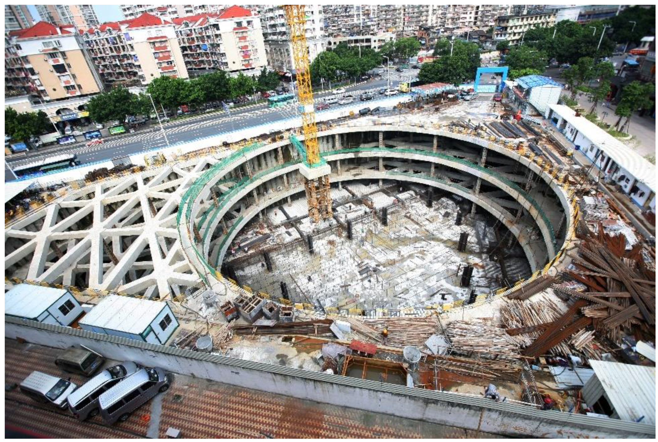
An image of the surrounding area of the foundation pit is shown in Figure 2. The northern boundary of the site’s basement is located approximately 4.5 m from the edge of Yingzhou Road, with a distance of approximately 22 m from the two-story wooden structures of Rongcheng Ancient Street, which have shallow foundations. On the western side of the site, the basement boundary is roughly 8.5 m away from the edge of Wuyi South Road. On the east side, the distance between the basement boundary and the existing five-story factory building, constructed as a masonry and reinforced concrete structure supported by a raft foundation, is approximately 15.0 m. The east side of the site is situated around 30.5 m away from the Yingzhou River. This project holds a Level I significance classification.

2.2. Geotechnical Conditions

Based on the geotechnical investigation conducted on the site, the sequence of geological layers within the influence range of the excavation of the foundation pit is as follows: Listed from top to bottom are miscellaneous fill (1-1), mucky fill (1-2), silt sand mixed with muck (2), muck mixed with sand (3), silt sand mixed with muck (4), muck mixed with sand (5), silt sand mixed with muck (6), mucky soil mixed with sand (7), silty sand (8), silty sand (9), and pebble (10). The physical and mechanical parameters of each geological layer can be found in Table 1.

2.3. Hydrogeological Conditions

The maximum excavation depth of this project is about 17 m, and the groundwater within the excavation area of the foundation pit is mainly as follows: The first type of groundwater is pore subsoil water in a loose layer, which mainly occurs in miscellaneous fill layer (1-1). This water-bearing medium is mostly filled with cohesive soil, with poor connectivity, weak water permeability, small aquifer thickness, and weak water-rich property. The second kind of groundwater is pore-confined water in a loose layer, which occurs in silt sand mixed with muck (2), silt sand mixed with muck (4), silt sand mixed with muck (6), silty sand (8), silty sand (9), and pebble (10). The medium structure of the aquifer above is relatively loose, the pore connectivity is good, and the water permeability is moderate to strong. The silty sand (8), silty sand (9), and pebble (10) aquifers have direct hydraulic connections. The layer with silt sand mixed with muck (2) has a buried depth of 3.40 to 3.50 m at static water level, the layer with silt sand mixed with muck (4) has a static water level buried depth of 7.30 to 7.60 m, and the layer with silt sand mixed with muck (6) has a static water level buried depth of 10.00 to 10.50 m. The initial groundwater level observed in the boreholes within the site ranges approximately from 2.94 to 4.16 m below the surface, whereas the depth of the mixed groundwater level ranges approximately from 2.78 to 3.88 m. The water level experiences an annual variation of around 0.5 to 1.0 m. The underground basement boundary on the southeastern side of the site is situated approximately 30.5 m away from the Yingzhou River, which spans about 16 m in width and flows in a northeasterly to southwesterly direction. The water depth in the river fluctuates between 1.0 and 5.0 m, influenced by the tidal movements of the Min River. The pore subsoil water of the loose layer on the surface of the site receives the supply of this water, and the surface water has a certain impact on the excavation of the basement foundation pit of this project. Protective measures, such as the construction of retaining walls and slope reinforcement, have been implemented along both banks of the river to ensure the current stability of the site.

3. Design Scheme of Foundation Pit Support and Construction Stage of Foundation Pit

3.1. Form of Enclosure Structure

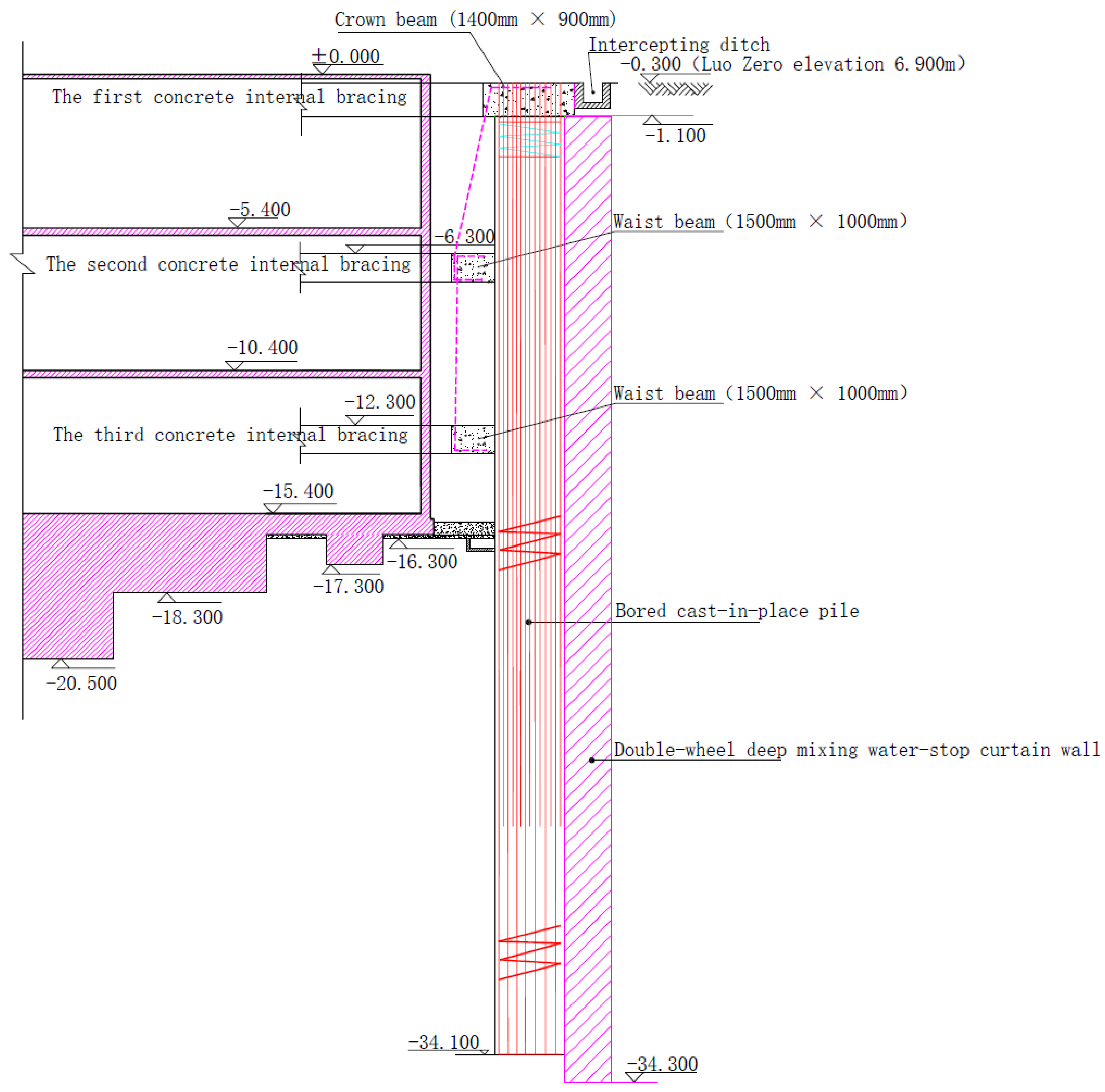
Based on the analysis of the surroundings of the foundation pit, the foundation pit is supported by cast-in-place piling and internal bracing. To reduce the impact on ground traffic and to control the deformation of the surrounding ground, the piles on the east side of the foundation pit near the plant are 1.1 m in diameter, 1.4 m in spacing, and 33 m long, and the piles in the remaining locations are 1.0 m in diameter, 1.3 m in spacing, and 32 m long. To ensure the water retention effect and reduce the impact of precipitation on the surrounding environment, in this foundation pit project, an 800 mm thick double-wheel deep-mixing water-stopping curtain wall is used on the outside of the enclosure pile to retain water; the curtain wall’s depth is 34 m. The profile view of the supporting structure is shown in Figure 3.

3.2. Foundation Pit Precipitation and Drainage

This foundation pit project uses tube wells for rainfall and catchment trenches at the top of the slope. A 400 mm × 400 mm collection trench is constructed around the perimeter of the pit, and a 600 mm × 600 mm collection well is constructed at 30 m intervals. A submersible pump is used to extract groundwater from the catchment pit and discharge it into the cut-off trench at the top of the slope, which is then discharged into the municipal pipeline.

3.3. Construction Stage of Foundation Pit

The construction process of the foundation pit is as follows: First, the construction of the cast-in-place pile and crown beam begins before foundation pit excavation, and the cast-in-place pile and crown beam are maintained after construction. When the strength of the cast-in-place pile and crown beam meets the design requirements, the foundation pit excavation begins. When the foundation pit is excavated to the bottom elevation of the first concrete internal bracing, the construction of the first concrete internal bracing begins. When the strength of the first internal bracing meets the design requirements, the foundation pit excavation begins. When the foundation pit is excavated to the bottom elevation of the second concrete internal bracing, the construction of the second concrete internal bracing begins. When the strength of the second internal bracing meets the design requirements, the foundation pit excavation begins. When the foundation pit is excavated to the bottom elevation of the third concrete internal bracing, the construction of the third concrete internal bracing will begin. When the strength of the third internal bracing meets the design requirements, the excavation of the foundation pit begins. When the foundation pit is excavated to the bottom elevation of the platform and bottom plate, the construction of the platform and bottom plate begins. When the strength of the platform and bottom plate meets the design requirements, the construction of the shear wall in the basement begins. Until the construction of the basement is completed, the construction of the entire foundation pit will be completed. The construction stage of the foundation pit is shown in Table 2.

4. Analysis of Site Monitoring Data

Given the extensive excavation area, considerable depth, and complex geological conditions of this foundation pit project, the selection of monitoring items should be based on careful consideration of the engineering and hydrogeological conditions, pit classification, characteristics of the support structure, and deformation control requirements. In addition to conventional inspection through visual inspection and inspection with the aid of other tools, the main instrumentation monitoring items are as follows: (1) the monitoring of the deep horizontal displacement of the enclosure pile; (2) the monitoring of the horizontal displacement at the top of foundation pit; (3) the monitoring of the settlement at the top of the foundation pit; (4) the monitoring of the axial force of the internal bracing; (5) the monitoring of the axial force of the enclosure pile; (6) the monitoring of the settlement of the column; (7) the monitoring of the groundwater level; (8) the monitoring of the layered settlement of the soil; (9) the monitoring of the settlement of the surrounding buildings; (10) the monitoring of the horizontal displacement of the surrounding buildings; (11) the monitoring of the tilt of the surrounding buildings; and (12) the monitoring of settlement of the surrounding surface and underground pipelines. The plan layout of the foundation pit monitoring points is shown in Figure 4, and the number of monitoring points, monitoring methods, and instrument names are shown in Table 3.

4.1. Monitoring of the Deep Horizontal Displacement of the Enclosure Pile

Along the key parts around the foundation pit, nine holes for monitoring the deep horizontal displacement of the retaining piles were arranged, numbered C1 to C9. The height of the inclinometer hole was equivalent to the height of the ground, and the hole depth was 34 m. The maximum horizontal displacement of the deep layer of the enclosure pile at each monitoring point is shown in Table 4.
It can be seen from Table 3 that the cumulative displacement of the piles at the C1 and C2 monitoring points is relatively small. This is because the surrounding buildings on one side of C1 and C2 points are only one-story staff dormitory and concierge, which have little impact on the foundation pit. The cumulative displacement of the piles from C3 to C9 monitoring points is larger because there are both roads and multi-story concrete buildings on the side of C3 to C9, coupled with the disturbance of vehicles, which has a great impact on the foundation pit. In the process of earthwork excavation and foundation construction of the foundation pit, the cumulative displacement of the piles from C3 to C9 monitoring points exceeded the design alarm value (30 mm), but the deformation was stable. The cumulative displacement change rate of the piles from C3 to C9 monitoring points did not exceed the alarm value.

4.2. Monitoring of the Horizontal Displacement at the Top of the Foundation Pit

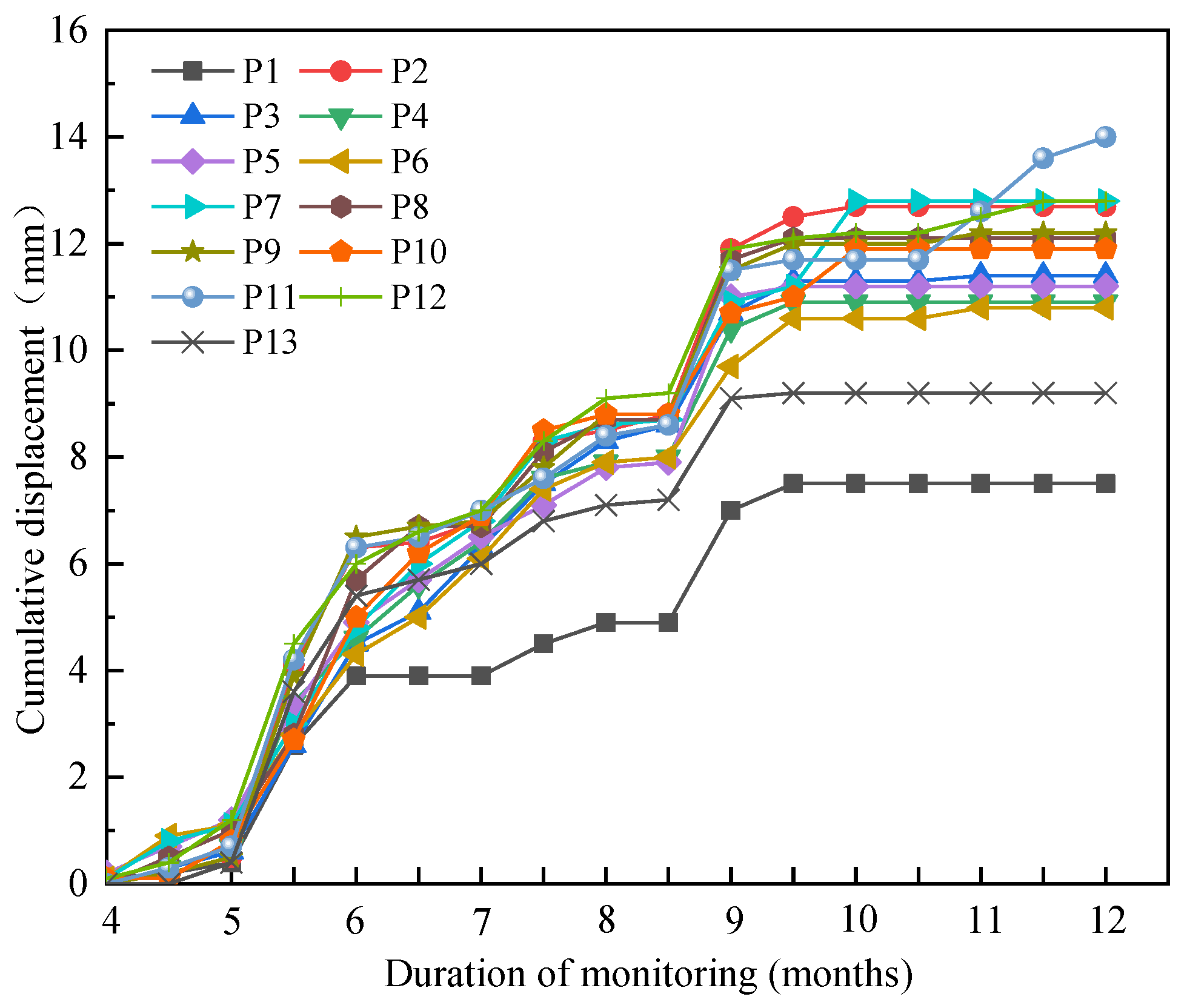
At the top of the foundation pit, 13 horizontal displacement monitoring points were arranged along the periphery, numbered P1 to P13. The observation mark was driven into the top of the crown beam with a measuring nail. Theodolites were used to monitor the horizontal displacement of these 13 points at the top of the foundation pit. The monitoring results are shown in Figure 5.
It can be seen from Figure 5 that, among the 13 monitoring points, the point with the largest cumulative horizontal displacement was the monitoring point P11, with a cumulative displacement of 14.0 mm. The point with the smallest cumulative horizontal displacement was the monitoring point P1, with a displacement of 7.5 mm. It can also be seen from Figure 5 that when the earthwork of the foundation pit was excavated, the horizontal displacement at the top of the foundation pit gradually increased with the increase in the excavation depth. The displacement accumulation and displacement increase rate of each monitoring point in the excavation process did not exceed the design alarm value. During the construction of the basement floor and shear walls after the completion of earth excavation, the horizontal displacement at the top of the foundation pit did not increase significantly, and the horizontal deformation at the top of the foundation pit tended to be stable. During the entire earthwork excavation and foundation construction process of the foundation pit, the accumulated horizontal displacement value and deformation rate at the top of the foundation pit did not exceed the design alarm value, thus meeting the requirements of the design and specifications.

4.3. Monitoring of the Settlement at the Top of the Foundation Pit

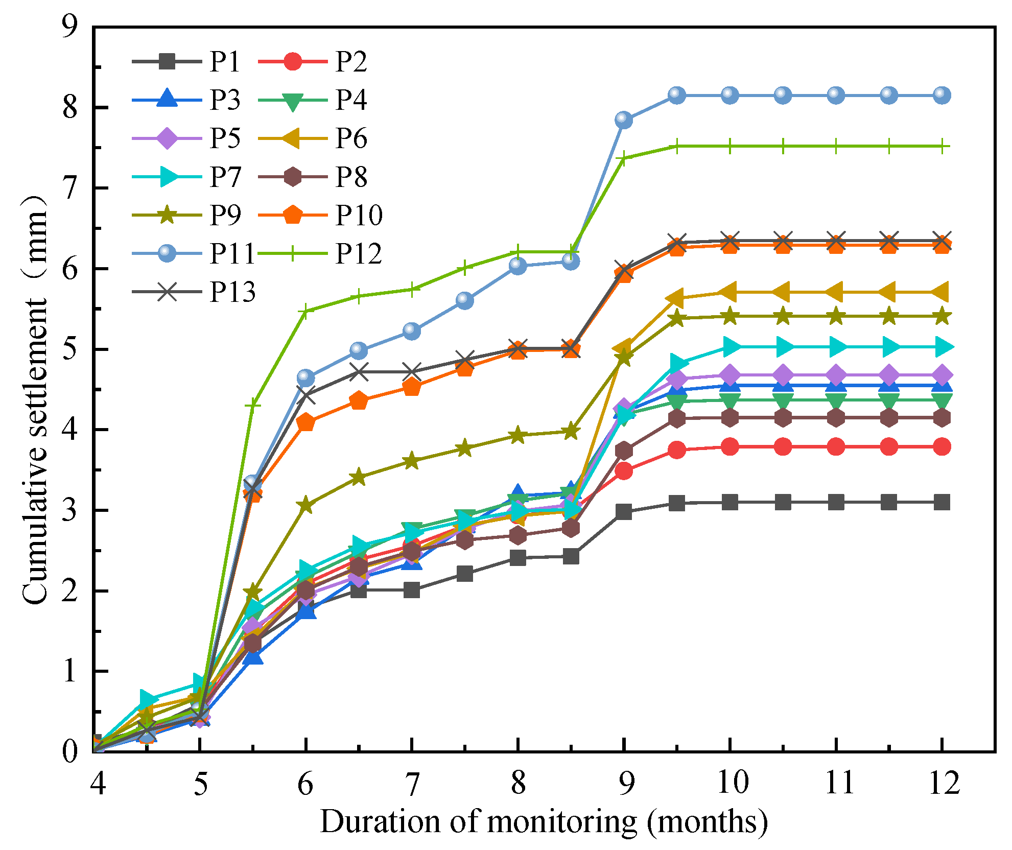
At the top of the slope, 13 settlement monitoring points were arranged along the periphery, numbered P1to P13. The observation mark was driven into the top of the crown beam with a measuring nail. Levels were used to monitor these 13 points at the top of the foundation pit. The monitoring results are shown in Figure 6.
It can be seen from Figure 6 that, among the 13 monitoring points, the point with the maximum cumulative value of vertical displacement was the monitoring point P11, with a displacement value of 8.15 mm. The point with the minimum cumulative value of vertical displacement was the monitoring point P1, with a displacement value of 3.10 mm. It can also be seen from Figure 6 that when the earthwork of the foundation pit was excavated, the cumulative vertical displacement at the top of the foundation pit gradually increased with the increase in the excavation depth. The settlement accumulation and settlement rate in the excavation process did not exceed the design requirement alarm value. During the construction of the basement floor and shear walls after the excavation of the earth, the vertical displacement at the top of the foundation pit did not increase significantly, and the vertical displacement at the top of the foundation pit tended to be stable. During the entire earthwork excavation and foundation construction process of the foundation pit, the accumulated vertical displacement and deformation rate at the top of the foundation pit did not exceed the design alarm value, which met the requirements of the design and specifications.

4.4. Monitoring of the Axial Force of the Internal Bracing

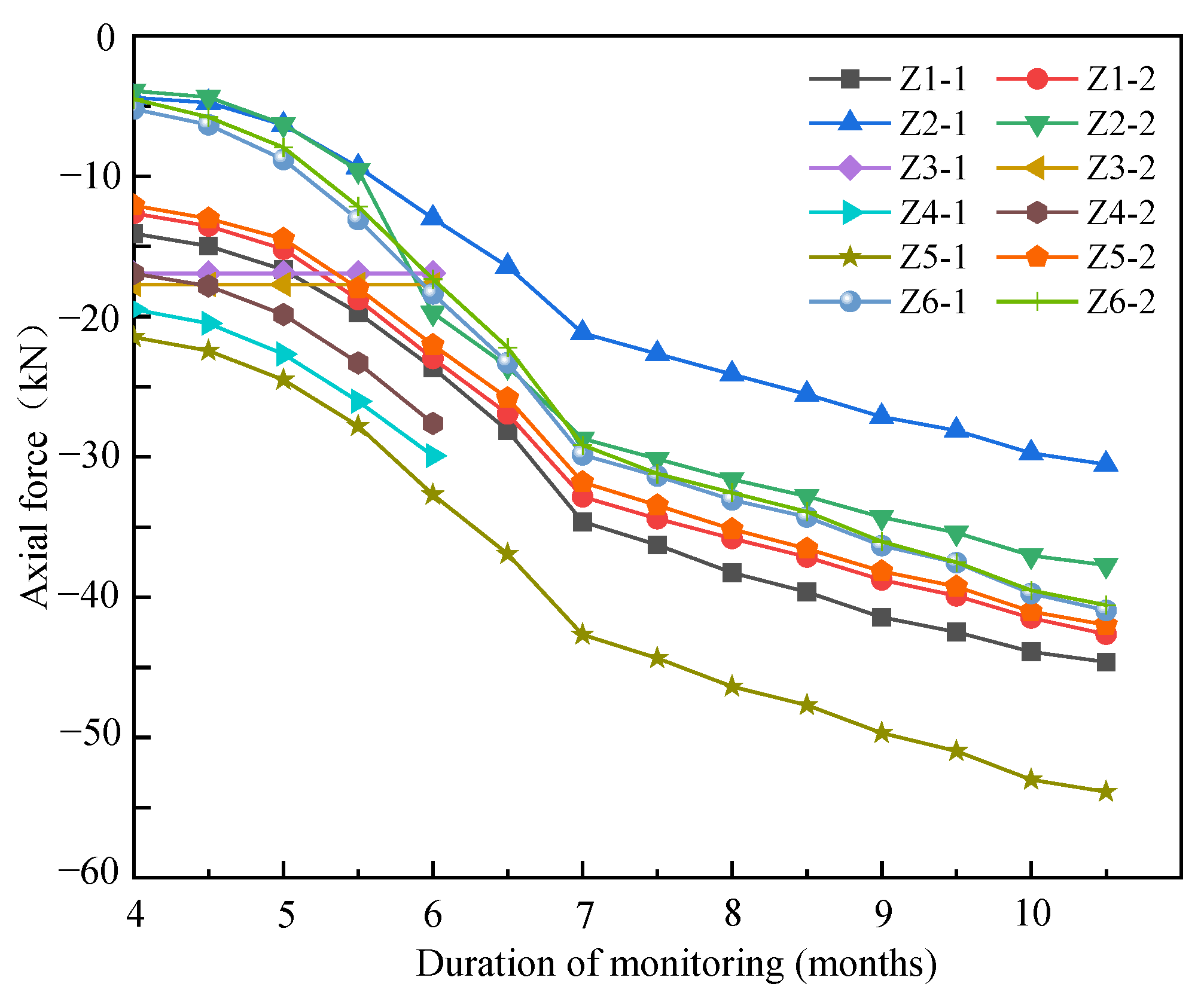
Considering the importance of the location of internal bracing, six monitoring points were arranged for the first reinforced concrete internal bracing, numbered Z1 to Z6. A rebar axial dynamometer was placed on the beam surface and the beam bottom at each point, and the layout method was welding the rebar axial dynamometer and the main bar in series. The monitoring results are shown in Figure 7.
As shown in Figure 7, the Z3 and Z4 monitoring points on the first reinforced concrete internal bracing had no monitoring data after the third month, which is mainly because the Z3 and Z4 monitoring points were destroyed during the construction process in the third month. From the variation curves of the Z1, Z2, Z5, and Z6 monitoring points, it can be seen that, before the 7th month, the axial force value of the first reinforced concrete internal bracing gradually increased with the excavation depth of the foundation pit, and the increase rate was faster. After the 7th month, when the construction of the shear wall began after the excavation of the foundation pit, the axial force of the first reinforced concrete internal bracing also increased gradually, but the increase rate slowed down noticeably. In the process of monitoring, the axial force of the first reinforced concrete internal bracing did not exceed the alarm value, thus meeting the design requirements.

4.5. Monitoring of the Axial Force of the Enclosure Pile

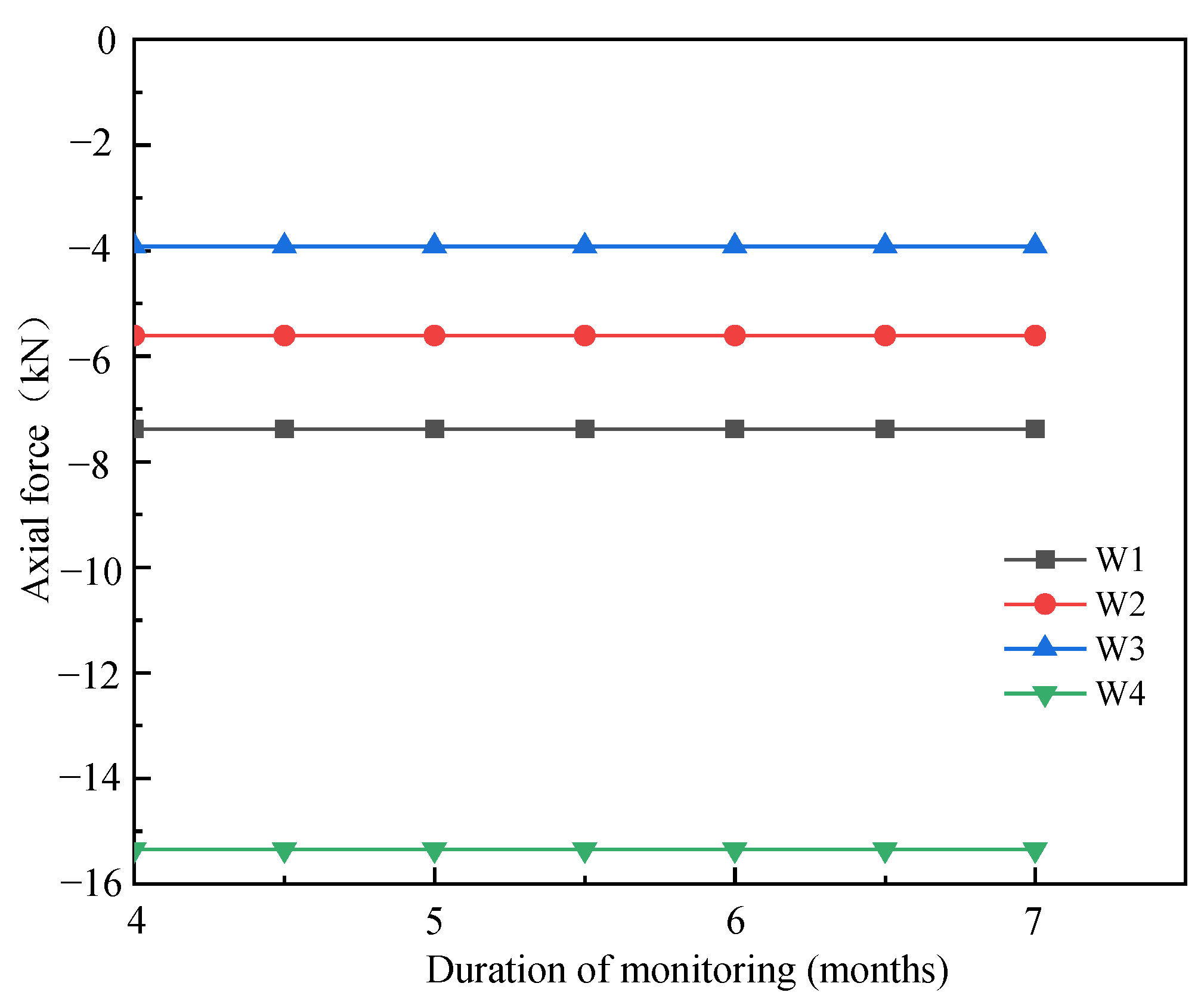
A total of four monitoring points were arranged on the enclosure pile, numbered W1 to W4. A rebar axial dynamometer was arranged at each point, and the layout method was welding the rebar axial dynamometer in series with the main reinforcement of the enclosure pile. The monitoring results are shown in Figure 8.
It can be seen from Figure 8 that the axial force value of the enclosure pile remains basically unchanged with the increase in the excavation depth of the foundation pit. Among the four monitoring points, the axial force value at point W4 was the largest, and the axial force value was 15.35 kN. The axial force value of the W3 point was the smallest, and the axial force value was 3.92 kN. During the monitoring process, the axial force data of each point of the enclosure pile did not exceed the alarm value, and the axial force of the pile body was within the design allowable range and therefore met the design requirements.

4.6. Monitoring of the Settlement of the Column

There were 28 settlement monitoring points at the top of the column, numbered L1 to L28. The observation mark was driven into the top of the column with a measuring nail. The level was used to monitor the 28 column-settlement monitoring points, and the monitoring results of column settlement are shown in Figure 9.
It can be seen from Figure 9 that the cumulative settlement of the L1 monitoring point is 0. Except for the L1 monitoring point, the cumulative settlement of other monitoring points increased at first and then remained basically unchanged. The settlement of L6, L8, L18, L19, L20, L21, L22, and L24 monitoring points remained basically unchanged after the 7th month, and the settlement of the other monitoring points remained basically unchanged after the 9th month. The maximum cumulative settlement occurred at the L10 monitoring point, and the displacement was 1.14 mm, which did not exceed the alarm value and therefore met the design requirements. This shows that there was no obvious settlement of the column in the whole process of foundation pit excavation and foundation construction, and the cumulative settlement and settlement rate did not exceed the alarm value in the whole process, thus meeting the requirements of the design.

4.7. Monitoring of the Groundwater Level

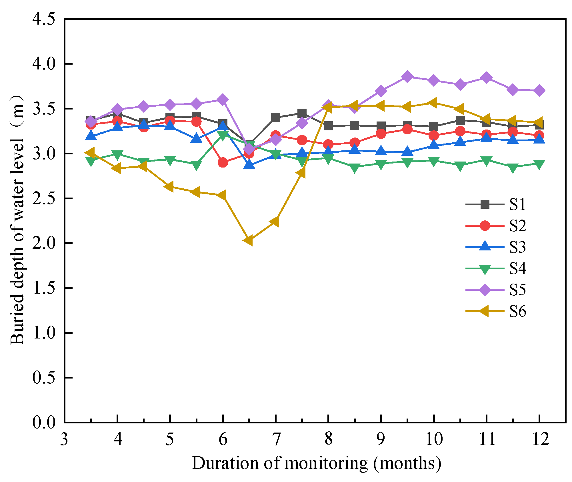
Six groundwater level observation holes were arranged along the key parts within 2 m outside the periphery of the foundation pit, numbered S1 to S6. The monitoring results of the groundwater level are shown in Figure 10.
It can be seen from Figure 10 that the groundwater level of the six monitoring points changes in a very small range, and the groundwater level outside the pit did not markedly change during the whole process of foundation pit excavation and foundation construction. This shows that the water-stopping effect of the enclosure structure of the foundation pit project is good. At the same time, the whole process of foundation pit dewatering had no obvious impact on the surrounding environment and therefore met the design requirements.

4.8. Monitoring of the Layered Settlement of the Soil

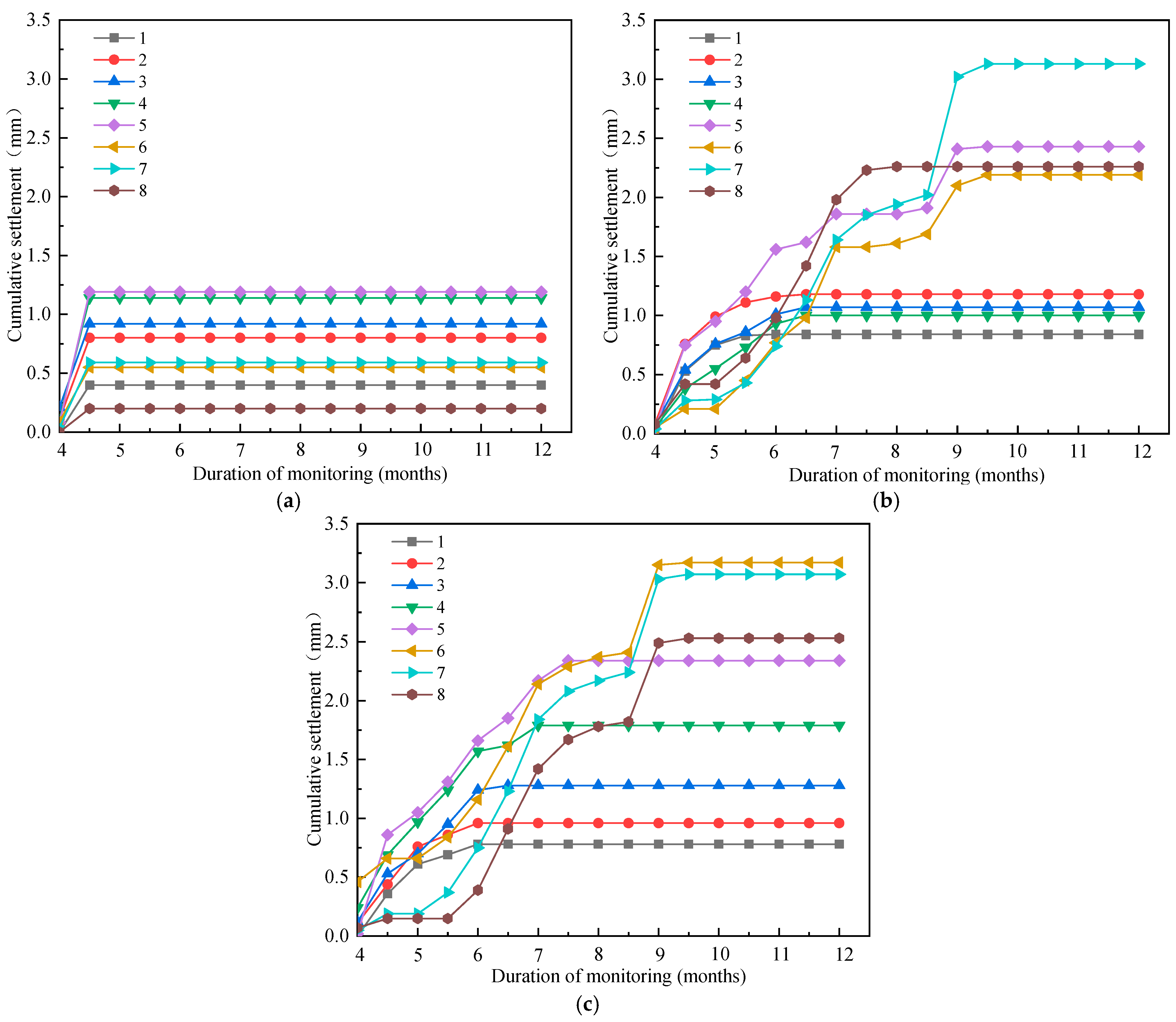
The layered settlement of the soil was monitored by laying a layered settlement magnetic ring and using a layered settlement meter combined with a leveling method for measurement. In this project, a total of three monitoring points for layered soil settlement were arranged in representative parts close to the protected objects, numbered F1 to F3. Five settlement magnetic rings were arranged vertically and equidistantly in the settlement tube at each point, the settlement tube depth was 40 m, and the vertical spacing of each magnetic ring was 5 m. A stratified sedimentation meter was used to monitor the three monitoring points of layered settlement of soil, and the monitoring results are shown in Figure 11.
It can be seen from Figure 11 that the cumulative settlements of the three monitoring points all showed a law of first increasing and then remaining unchanged. The largest accumulative settlement occurred in F3 monitoring point, and the settlement was 3.17 mm, which did not exceed the design alarm value. This shows that, during the whole process of foundation pit excavation and foundation construction, the soil did not significantly settle, and the cumulative settlement and settlement rate did not exceed the alarm value, thus meeting the design requirements.

4.9. Monitoring of the Settlement of the Surrounding Buildings

Nineteen settlement monitoring points were set up in the corner of the outer wall and other key deformation parts of the Rongcheng ancient street building on the north side of the foundation pit and the factory building on the east side of the foundation pit, numbered J1 to J19. The observation sign was fixed on the wall or column by using the existing settlement observation point of the building or with expansion bolts. The level was used to monitor the settlement of these 19 points, and the monitoring results are shown in Figure 12.
It can be seen from Figure 12 that, before the 8th month, the cumulative settlement of each monitoring point increased with the increase in the excavation depth of the foundation pit. From the initiation of the project to the 4.5th month, the cumulative settlement of the monitoring points increased at a large rate. From the 4.5th month to the 8th month, the cumulative settlement growth rate of the monitoring points decreased significantly. After the 8th month, the cumulative settlement of each monitoring point remained basically unchanged. The point of the maximum cumulative settlement was the J7 monitoring point, with a deformation value of 12.42 mm. The minimum cumulative settlement occurred at the J17 monitoring point, with a deformation value of 7.05 mm. This shows that the whole foundation pit excavation and foundation construction process of the project did not have a significant impact on the surrounding buildings, and the monitoring data did not exceed the alarm value, thus meeting the design requirements.

4.10. Monitoring of the Horizontal Displacement of the Surrounding Buildings

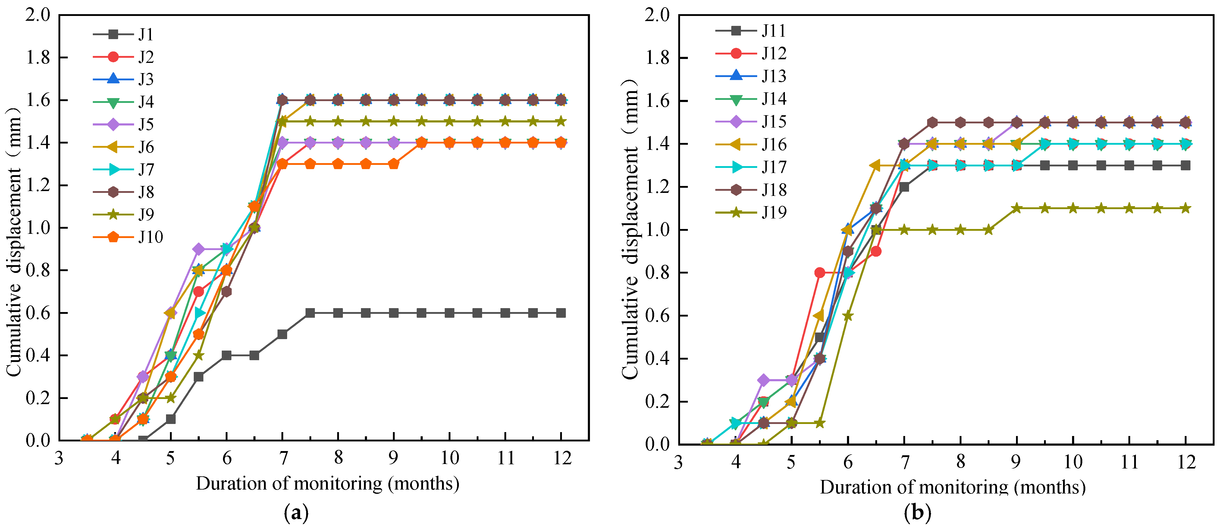
Nineteen horizontal displacement monitoring points were set up in the corner of the outer wall and other key deformation parts of the Rongcheng ancient street building on the north side of the foundation pit and the factory building on the east side of the foundation pit, numbered J1 to J19. Theodolites were used to monitor the horizontal displacement of these 19 points, and the monitoring results are shown in Figure 13.
It can be seen from Figure 13 that, before the 7th month, the cumulative horizontal displacement of each monitoring point increased with the increase in the excavation depth of the foundation pit. After the 7th month, the cumulative horizontal displacement of each monitoring point remained basically unchanged. The maximum cumulative horizontal displacement occurred at the J3 monitoring point, and the horizontal displacement was 1.6 mm. The minimum cumulative horizontal displacement occurred at the J1 monitoring point, and the horizontal deformation value was 0.6 mm. This shows that the earthwork excavation and foundation construction of the foundation pit project had very little impact on the surrounding buildings, and the monitoring data did not exceed the alarm value, which met the design requirements.

4.11. Monitoring of Tilt of the Surrounding Buildings

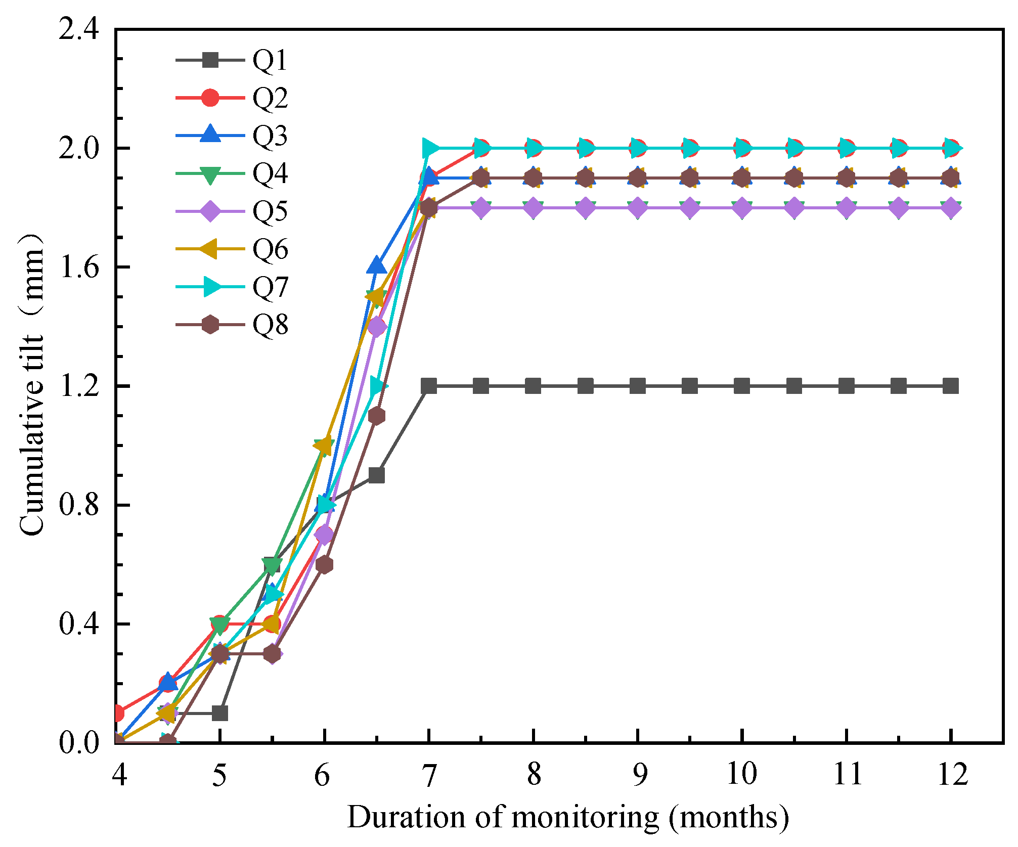
Tilt monitoring points were arranged on the key deformation parts of the building within two times the excavation depth of the foundation pit excavation boundary line, and a total of eight tilt monitoring points were arranged, numbered Q1 to Q8. Theodolites were used to monitor the tilt monitoring points of the surrounding buildings, and the tilt monitoring results of the surrounding buildings are shown in Figure 14.
It can be seen from Figure 14 that, before the 7th month, when the foundation pit was excavated, and the foundation was constructed, the cumulative tilt of the surrounding buildings increased with the excavation depth of the foundation pit. After the 7th month, when the foundation pit excavation and foundation construction were completed, and the basement shear wall construction started, the cumulative tilt of the surrounding buildings remained basically unchanged. During the whole monitoring process, the point with the maximum cumulative tilt was the Q2 monitoring point, and the tilt value was 2.0 mm. The point with the minimum cumulative tilt was the Q1 monitoring point, and the tilt value was 1.2 mm. This shows that the whole foundation pit excavation and foundation construction process of this project did not have a significant impact on the surrounding buildings, and none of the monitoring data exceeded the alarm value, which met the design requirements.

4.12. Monitoring of Settlement of the Surrounding Surface and Underground Pipelines

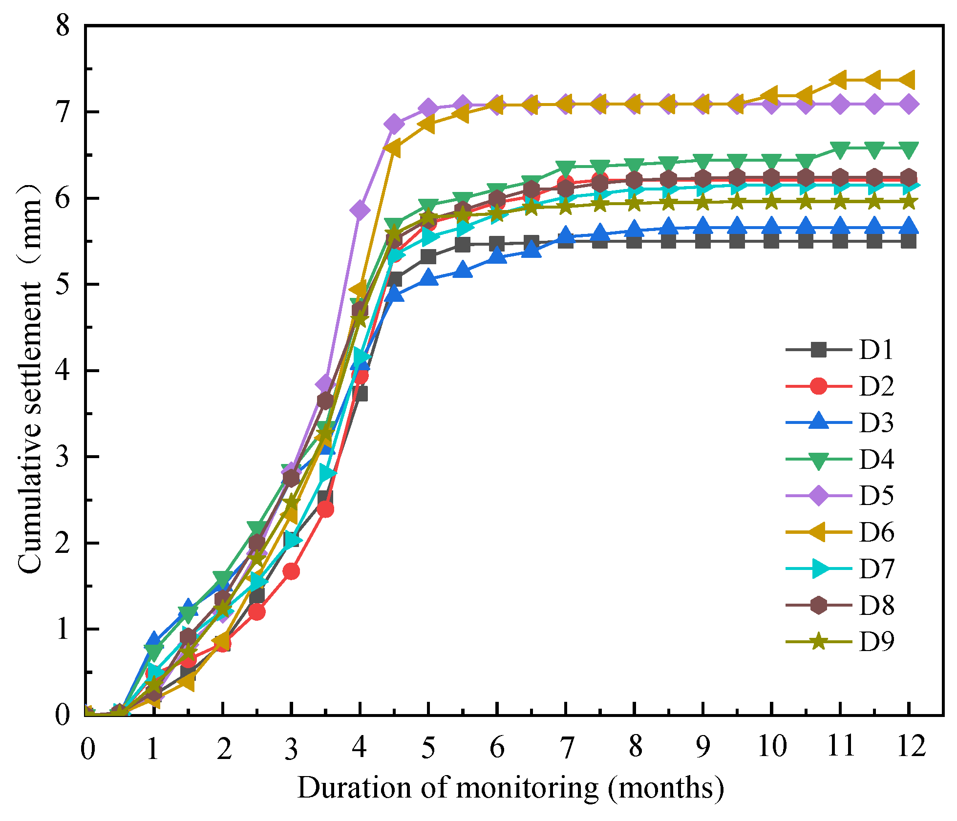
In the range of three times the excavation depth of the foundation pit from the boundary line of the foundation pit, nine settlement monitoring points were arranged on the surface and underground pipelines, numbered D1 to D9. The observation mark was driven into the ground with a measuring nail. The level was used to monitor the settlement of these nine points, and the monitoring results are shown in Figure 15.
It can be seen from Figure 15 that, before the 8th month, the cumulative settlement of each monitoring point increased with the increase in the excavation depth of the foundation pit. From the start of the project to the 4.5th month, the cumulative settlement growth rate of the monitoring point was relatively fast, and from the 4.5th month to the 8th month, the cumulative settlement growth rate of the monitoring point decreased significantly. After the 8th month, the cumulative settlement of each monitoring point remained basically unchanged. In the whole monitoring process, the maximum cumulative settlement occurred at the D6 monitoring point, and the settlement value was 7.37 mm. The minimum cumulative settlement occurred at the D1 monitoring point, and the settlement value was 5.50 mm. This shows that the whole process of foundation pit excavation and foundation construction had no obvious impact on the surrounding surface and underground pipelines, and the monitoring data of the project did not exceed the alarm value, which met the design requirements.

5. Conclusions

The surrounding area of the foundation pit of the Taijiang Square project in Fuzhou is complex, and the safety grade is high. The cast-in-place pile enclosure structure and three reinforced concrete internal bracing are adopted for support. In the whole process of foundation pit construction, 12 items such as the deep horizontal displacement of the enclosure pile, the horizontal displacement at the top of the foundation pit, the settlement at the top of the foundation pit, the axial force of internal bracing, and the axial force of the enclosure pile were monitored, and the following conclusions were drawn by analyzing the monitoring data of each item:
(1) During the construction of the foundation pit, the monitoring values of 12 monitoring items, including the deep horizontal displacement of the retaining pile, the horizontal displacement at the top of the foundation pit, the settlement at the top of the foundation pit, the axial force of the support, and the axial force of the retaining pile, did not exceed the alarm value, which met the design requirements.
(2) The support scheme of the cast-in-place pile enclosure structure and three internal bracing is reasonable and can effectively control the deformation of the foundation pit in soft soil areas.
(3) Tube-well dewatering can effectively lower the groundwater level below the bottom of the foundation pit, and the double-wheel deep-mixing water-stopping curtain wall can effectively control the infiltration of water outside the foundation pit.
(4) This foundation pit project is representative, and it provides a good reference case for the design of water-bearing deep foundation pit projects in the soft soil areas of Fuzhou.

Author Contributions

Conceptualization, B.T. and W.N.; methodology, J.Z. and M.S.; validation, B.T., W.N. and J.Z.; formal analysis, B.T.; investigation, M.S.; resources, B.T. and W.N.; data curation, J.Z. and M.S.; writing—original draft preparation, B.T.; writing—review and editing, W.N.; supervision, W.N.; project administration, M.S.; funding acquisition, B.T. and W.N. All authors have read and agreed to the published version of the manuscript.

Funding

This research was funded by the Collaborative Innovation Platform Project of Fuzhou-Xiamen–Quanzhou National Self-Innovation Zone under Grant No. 3502ZCQXT2022002; the Science and technology plan of Fujian Province under Grant No. 2022I0014; the Supported by Construction Technology Project of Xiamen Municipal Construction Bureau under Grant No. XJK2022-1-12; and the Supported by the Fundamental Research Funds for the Central Universities under Grant No. ZQN-1012.

Data Availability Statement

The monitoring data used for this research are not freely available due to legal concerns and commercial confidentiality. Nevertheless, all the concepts and procedures are explained in the presented research, and parts of the research may be available upon request.

Conflicts of Interest

The authors declare that they have no conflict of interest.

References

  1. Rodriguez, J.A. Deep excavations for buildings in the Sabana Formation Bogota. In Proceedings of the 10th International Symposium on Geotechnical Aspects of Underground Construction in Soft Ground (IS-Cambridge), Cambridge, UK, 27–29 June 2022; pp. 145–152. [Google Scholar]
  2. Fan, N.; Nian, T.K.; Guo, X.S.; Jiao, H.B. Piecewise strength model for three types of ultra-soft fine-grained soils. Soils Found. 2020, 60, 778–790. [Google Scholar] [CrossRef]
  3. Gotman, A.L.; Gotman, Y.A. Numerical Analysis of the Shorings of Deep Foundation Pits with Regard for the Soil Solid-ification. Soil Mech. Found. Eng. 2019, 56, 225–231. [Google Scholar] [CrossRef]
  4. Hettler, A.; Becker, P.; Borchert, K.M.; Kinzler, S. Report of the working group for recommendations on excavations: Outlook 6th edition EAB—Underpinnings, excavations in soft soils, head deformations of non-supported walls. Bautechnik 2019, 96, 785–792. [Google Scholar] [CrossRef]
  5. Jun, S.H.; Kwon, H.J. Constitutive Relationship Proposition of Marine Soft Soil in Korea Using Finite Strain Consolidation Theory. J. Mar. Sci. Eng. 2020, 8, 429. [Google Scholar] [CrossRef]
  6. Sun, Q.Q.; Dias, D.; Sousa, L.R.E. Soft soil layer-tunnel interaction under seismic loading. Tunn. Undergr. Space Technol. 2020, 98, 103329. [Google Scholar] [CrossRef]
  7. Qiao, F.; Bo, J.S.; Wang, L.; Chang, C.Y.; Zhang, Z.P.; Qi, W.H. Survey of China’s soft soil and its dynamic characteristics. World Earthq. Eng. 2019, 35, 150–161. [Google Scholar]
  8. Ye, S.H.; Zhao, Z.F.; Wang, D.Q. Deformation analysis and safety assessment of existing metro tunnels affected by excavation of a foundation pit. Undergr. Space 2021, 6, 421–431. [Google Scholar] [CrossRef]
  9. Takada, N.; Simono, K.; Oka, F.; Kimoto, S.; Higo, Y.A. Numerical evaluation of the deformation of earth retaining wall reinforced by soil buttress method during the excavation in soft soil. In Proceedings of the Computer Methods and Recent Advances in Geomechanics, Kyoto, Japan, 22–25 September 2014; pp. 1037–1042. [Google Scholar]
  10. Zheng, G. Method and application of deformation control of excavations in soft ground. Chin. J. Geotech. Eng. 2022, 44, 1–36. [Google Scholar]
  11. Song, X.G.; Wang, Z.Y.; Bai, W.W.; Wang, Z.; Xie, S.M.; Xia, K.Z. Study on engineering characteristics of large-scale deep soft soil in the central area of western Zhuhai. Chin. J. Rock Mech. Eng. 2019, 38, 1434–1451. [Google Scholar]
  12. Zhang, Y.C.; Yang, G.H.; Hu, H.Y.; Chen, F.Q.; Huang, Z.X.; Chen, W.C. Some problems about retaining structures for shallow pits in deep and soft soil areas of Pearl River Delta. Chin. J. Geotech. Eng. 2014, 36, 1–11. [Google Scholar]
  13. Ye, S.H.; Zhou, J. Study on stress and deformation of shield tunnel plate under unloading of foundation pit excavation. Arab. J. Geosci. 2021, 14, 2490. [Google Scholar] [CrossRef]
  14. Yuan, C.F.; Hu, Z.H.; Zhu, Z.; Yuan, Z.J.; Fan, Y.X.; Guan, H.; Li, L. Numerical Simulation of Seepage and Deformation in Excavation of a Deep Foundation Pit under Water-Rich Fractured Intrusive Rock. Geofluids 2021, 2021, 6628882. [Google Scholar] [CrossRef]
  15. Harahap, S.E.; Ou, C.Y. Finite element analysis of time-dependent behavior in deep excavations. Comput. Geotech. 2020, 119, 103300. [Google Scholar] [CrossRef]
  16. Bal, A.R.L.; Dang, T.S.; Meschke, G. A 3D particle finite element model for the simulation of soft soil excavation using hypoplasticity. Comput. Part. Mech. 2020, 7, 151–172. [Google Scholar] [CrossRef]
  17. Uribe-Henao, A.F.; Arboleda-Monsalve, L.G.; Mackie, K. Soil-Structure Interaction on Excavation-Induced Response of Mo-ment-Resisting Frame Buildings. In Proceedings of the 2nd Geo Congress—Deep Foundations, Earth Retention, and Under-ground Construction, Charlotte, NC, USA, 20–23 March 2022; pp. 341–350. [Google Scholar]
  18. Sun, F.X.; Liu, M.Q.; Zhu, Y.H.; Li, X.C.; Ge, G. Research on Numerical Simulation of Top-Down Construction Effect of Diaphragm Wall of Deep and Large under Different Working Conditions in Complex Stratum. Adv. Civ. Eng. 2022, 2022, 2576122. [Google Scholar] [CrossRef]
  19. Wu, J.; Ye, S.H.; Wang, Z.Q.; Yang, D. Application and automatic monitoring and analysis of hybrid support structure in ultra-deep foundation pit engineering in the Lanzhou area under complex environmental conditions. Water 2023, 15, 1335. [Google Scholar] [CrossRef]
  20. Dmochowski, G.; Szolomicki, J. Technical and Structural Problems Related to the Interaction between a Deep Excavation and Adjacent Existing Buildings. Appl. Sci. 2021, 11, 481. [Google Scholar] [CrossRef]
  21. Chen, S.R.; Cui, J.F.; Liang, F.Y. Case Study on the Deformation Coupling Effect of a Deep Foundation Pit Group in a Coastal Soft Soil Area. Appl. Sci. 2022, 12, 6205. [Google Scholar] [CrossRef]
  22. Rybak, J.; Ivannikov, A.; Kulikova, E.; Zyrek, T. Deep excavation in urban areas—Defects of surrounding buildings at various stages of construction. In Proceedings of the 9th International Scientific Conference on Building Defects (Building Defects 2017), Ceske Budejovice, Czech Republic, 23–24 November 2017; p. 02012. [Google Scholar]
  23. Yang, T.; Liu, S.L.; Wang, X.Y.; Zhao, H.; Liu, Y.; Li, Y.W. Analysis of the Deformation Law of Deep and Large Foundation Pits in Soft Soil Areas. Front. Earth Sci. 2022, 10, 828354. [Google Scholar] [CrossRef]
  24. Sun, L.; Mao, K.; Wang, Z.Z.; Ye, S.H.; Su, T.T.; Dai, G.L.; Xu, G.X.; Sun, J.L. Design and Field Monitoring of a Pile-Anchor-Brace Supporting System in a Soft Soil Area. Water 2022, 14, 3949. [Google Scholar] [CrossRef]
  25. Chen, J.S.; Lin, C.; Liu, S.Z.; Mo, H.H. Study on Supporting Structure Performance of Deep Soft Soil Foundation Pit near Sea under Waves, Tides, Vibration, and Unbalanced Loads. Adv. Civ. Eng. 2020, 2020, 8830199. [Google Scholar] [CrossRef]
  26. Czajewska, M.M. A study of displacements of structures in the vicinity of deep excavation. Arch. Civ. Mech. Eng. 2019, 19, 547–556. [Google Scholar] [CrossRef]
  27. Feng, Z.Y.; Xu, Q.; Xu, X.Y.; Tang, Q.; Li, X.D.; Liao, X. Deformation Characteristics of Soil Layers and Diaphragm Walls during Deep Foundation Pit Excavation: Simulation Verification and Parameter Analysis. Symmetry 2022, 14, 254. [Google Scholar] [CrossRef]
  28. Panchal, J.P.; McNamara, A.M.; Stallebrass, S.E. A new approach to modelling excavations in soft soils. In Proceedings of the 9th International Conference on Physical Modelling in Geotechnics (ICPMG), London, UK, 17–20 July 2018; pp. 1445–1450. [Google Scholar]
  29. Kiet, H.N.; Phien-wej, N. Advanced soil parameters determination for Ho Chi Minh city soft clay to predict ground movements in deep excavations and tunneling. In Proceedings of the 4th International Conference on Geotechnics for Sustainable Infrastructure Development (GEOTEC HANOI), Hanoi, Vietnam, 28–29 November 2019; pp. 497–504. [Google Scholar]
  30. Nguyen, B.P.; Ngo, C.P.; Tran, T.D.; Bui, X.C.; Doan, N.P. Finite Element Analysis of Deformation Behavior of Deep Excavation Retained by Diagram Wall in Ho Chi Minh City. Indian Geotech. J. 2022, 52, 989–999. [Google Scholar] [CrossRef]
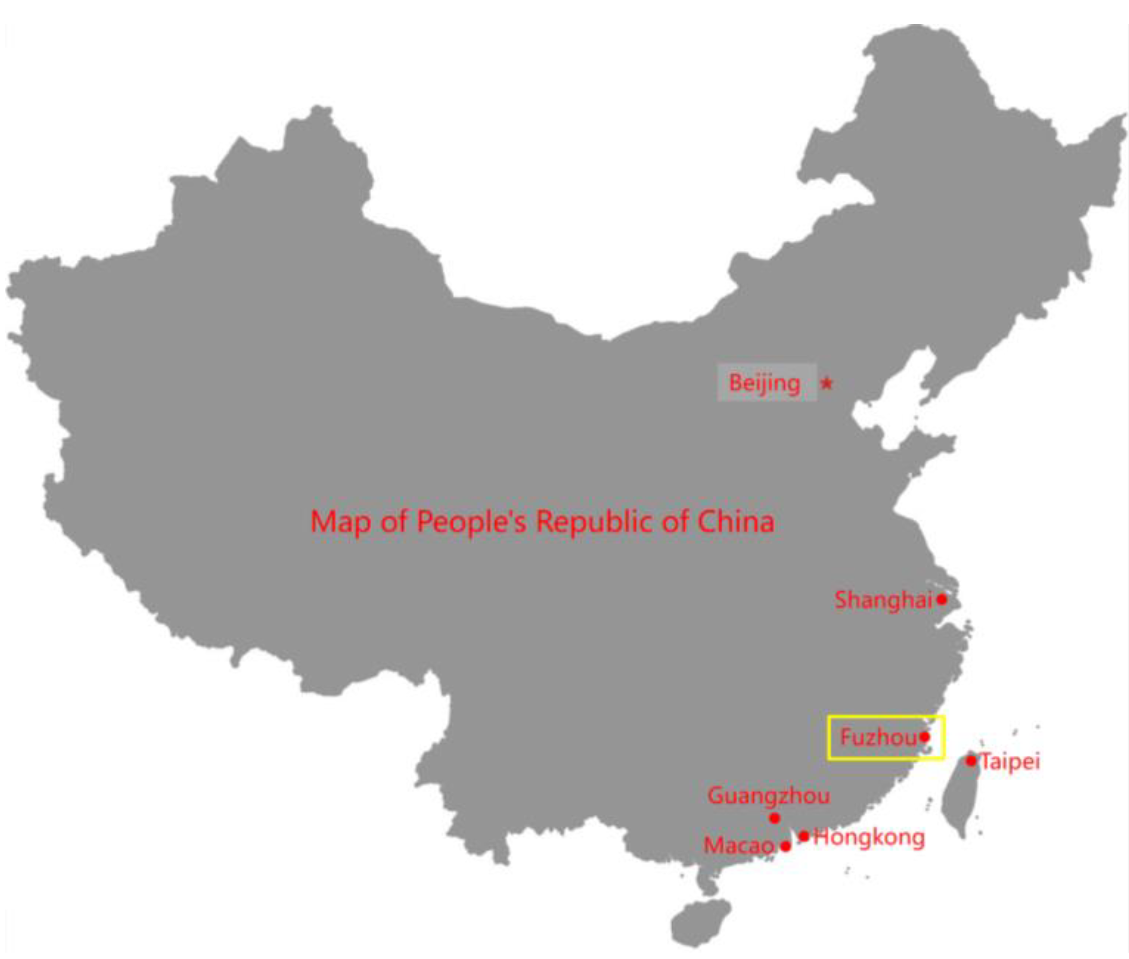
Figure 1. The general location map of Fuzhou.
Water 15 03008 g001
Figure 2. An image of the surrounding area of the foundation pit.
Water 15 03008 g002
Figure 3. The profile view of the supporting structure.
Water 15 03008 g003
Figure 4. The layout plan of monitoring points of the foundation pit.
Water 15 03008 g004
Figure 5. The time history curve of the horizontal displacement at the top of the foundation pit.
Water 15 03008 g005
Figure 6. The time history curve of the vertical displacement at the top of the foundation pit.
Water 15 03008 g006
Figure 7. The axial force variation curve for the first internal bracing.
Water 15 03008 g007
Figure 8. The axial force variation curve of the enclosure pile.
Water 15 03008 g008
Figure 9. Time history curve of vertical displacement of the column: (a) time history curve of vertical displacement of L1 to L14 columns; (b) time history curve of vertical displacement of L15 to L28 columns.
Water 15 03008 g009
Figure 10. The time history curve of groundwater level monitoring in the foundation pit.
Water 15 03008 g010
Figure 11. The time history curve of vertical displacement of each monitoring point in soil stratification: (a) the time history curve of F1 vertical displacement; (b) the time history curve of F2 vertical displacement; (c) the time history curve of F3 vertical displacement.
Water 15 03008 g011
Figure 12. The time history curve of cumulative settlement of surrounding buildings: (a) the time history curve of cumulative settlement at J1 to J10 monitoring points; (b) the time history curve of cumulative settlement at J11 to J19 monitoring points.
Water 15 03008 g012
Figure 13. The time history curve of cumulative horizontal displacement of surrounding buildings: (a) the time history curve of cumulative horizontal displacement at J1 to J10 monitoring points; (b) the time history curve of cumulative horizontal displacement at J11 to J19 monitoring points.
Water 15 03008 g013
Figure 14. The time history curve of the cumulative tilt of the surrounding buildings.
Water 15 03008 g014
Figure 15. The time history curve of the cumulative settlement of the surrounding surface and underground pipelines.
Water 15 03008 g015
Table 1. Physical and mechanical parameters of each geotechnical layer.
Soil LayerName of Soil LayerStatusThickness (m)Natural Heavy
γ/(kN/m3)
Cohesion
c/(kPa)
Internal Friction
Angle φ/(°)
1-1Miscellaneous fillSlightly denser1.50 to 8.3018.08.014.0
1-2Mucky fillFlow plastic1.20 to 5.3017.010.511.0
2Silt sand mixed with muckSlightly denser to medium density3.90 to 11.018.03.021.0
3Muck mixed with sand Flow plastic1.60 to 8.2016.28.910.5
4Silt sand mixed with muckMedium density2.70 to 11.318.25.023.0
5Muck mixed with sandFlow plastic1.80 to 9.016.611.011.0
6Silt sand mixed with muckMedium density to dense5.90 to 9.8518.45.026.0
7Mucky soil mixed with sandFlow plastic1.52 to 3.8716.912.013.0
8Silty sandMedium density to dense2.60 to 10.018.63.030.0
9Silty sanddense0.50 to 9.8018.73.033.0
10PebbleMedium density4.29 to 5.8021.0038.0
Table 2. The construction stage of the foundation pit.
Time (Months)Construction Stage
0–2.5Cast-in-place pile construction
2.5–3The first internal bracing construction
3–4Earthwork excavation
4–4.5The second internal bracing construction
4.5–5Earthwork excavation
5–5.5The third internal bracing construction
5.5–6Earthwork excavation
6–6.5Platform construction
6.5–7Bottom plate construction
7–12Shear wall construction
Table 3. Summary of monitoring points.
Monitoring ContentMonitoring MethodsInstrument NameNumber of Monitoring Points
Deep horizontal displacement of enclosure pileLevel survey (2nd class)Su Yiguang DSZ2 automatic leveling level and FS1 micrometer9
Horizontal displacement at the top of the foundation pitSmall angle method (Theodolite)Su Yiguang DT302L electronic theodolite13
Settlement at the top of the foundation pitInclinometerAmerican SINCO digital sliding inclinometer13
The axial force of internal bracingRebar stress gaugesJinyuan civil engineering CTY-202 frequency meter6
The axial force of the enclosure pileRebar stress gaugesJinyuan civil engineering CTY-202 frequency meter4
Settlement of the columnLevel survey (2nd class)Su Yiguang DSZ2 automatic leveling level and FS1 micrometer28
Groundwater levelWater level meterJinyuan civil engineering SJ-92 water level gauge6
Layered settlement of soilLevel survey (2nd class)Su Yiguang DSZ2 automatic leveling level and FS1 micrometer3
Settlement of surrounding buildingsSmall angle method (Theodolite)Su Yiguang DT302L electronic theodolite19
Horizontal displacement of surrounding buildingsPoint Casting Method (Theodolite)Su Yiguang DT302L electronic theodolite19
The tilt of surrounding buildingsLevel survey (2nd class)Su Yiguang DSZ2 automatic leveling level and FS1 micrometer8
Settlement of surrounding surface and underground pipelinesLevel survey (2nd class) and Stratified sedimentation meterSu Yiguang DSZ2 automatic leveling level, FS1 micrometer, and Wuhan foundation deep stratified sedimentation meter9
Table 4. Maximum horizontal displacement of enclosure pile in the deep layer at each monitoring point.
Monitoring PointC1C2C3C4C5C6C7C8C9
Maximum horizontal displacement (mm)13.366.7840.9641.4037.7044.2246.5252.6036.22
Disclaimer/Publisher’s Note: The statements, opinions and data contained in all publications are solely those of the individual author(s) and contributor(s) and not of MDPI and/or the editor(s). MDPI and/or the editor(s) disclaim responsibility for any injury to people or property resulting from any ideas, methods, instructions or products referred to in the content.