


Optimal Segmentation Approach for Reducing Water Outage Damage Considering Urbanization in Water Distribution Systems


Abstract
:1. Introduction
2. Optimal Segment Division Approach Based on Urbanization
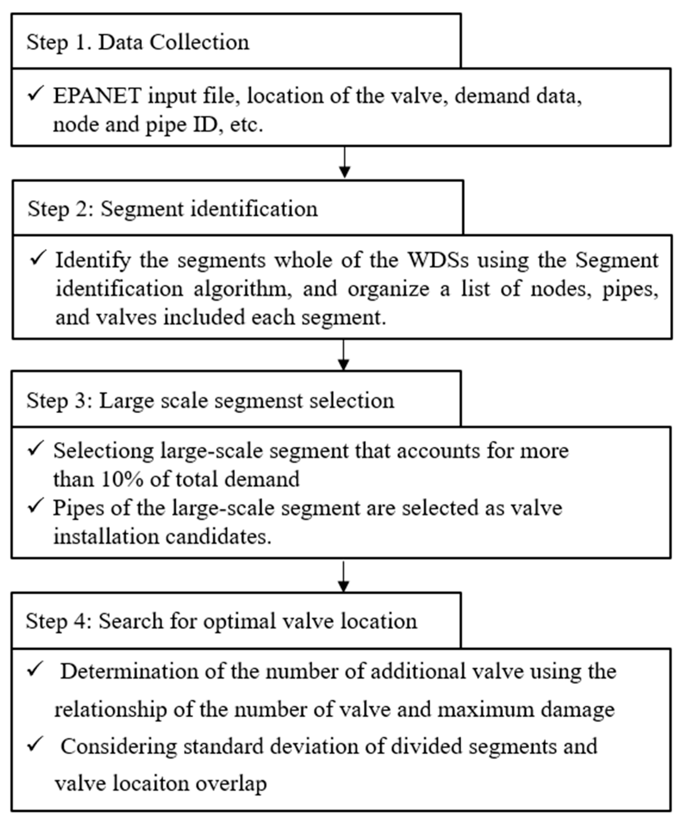
2.1. Segment Identification and Large-Scale Segment Selection
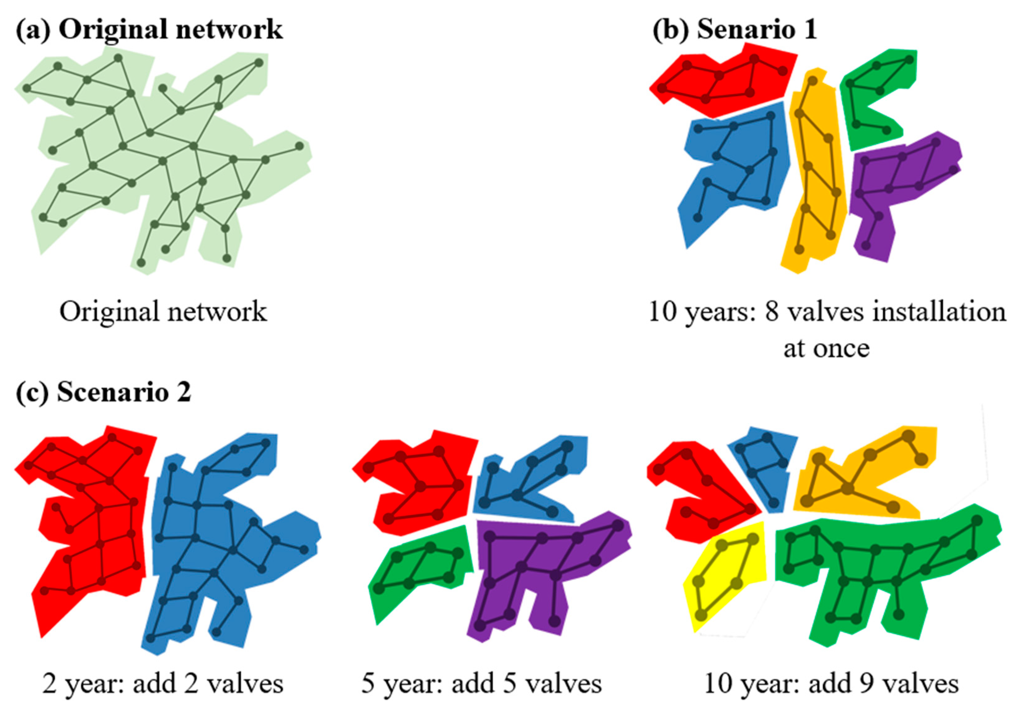
2.2. Segment Division Scenarios Considering Urbanization
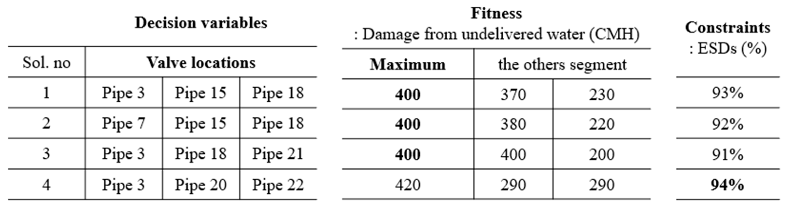
2.3. Determination of Optimal Valve Location
- (1)
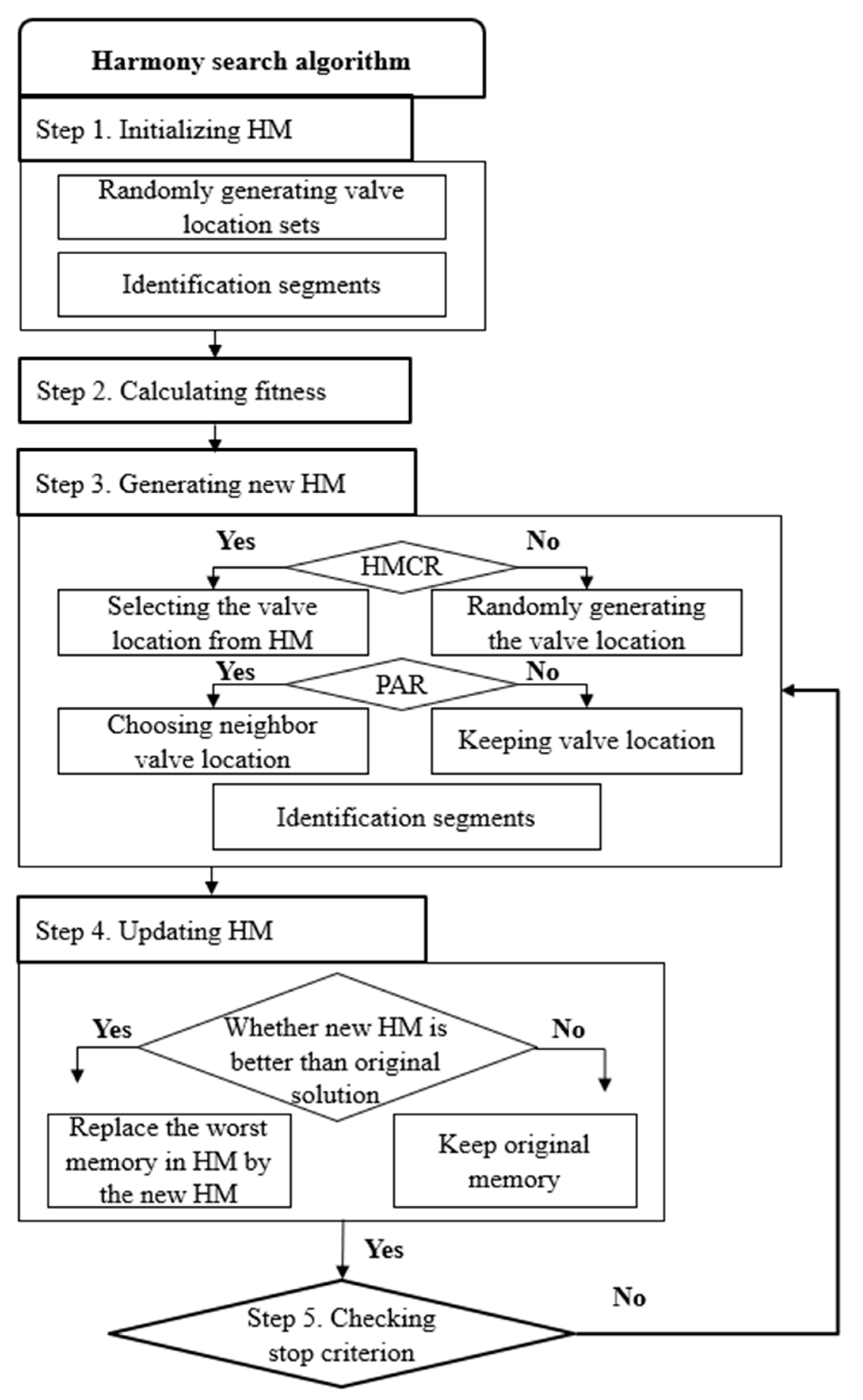
- An initial solution is generated based on the specified HMS.
- (2)
- The HMCR is applied to the initial solution, resulting in the creation of a new solution.
- (3)
- The PAR is applied to the new memory, adjusting the solution further.
- (4)
- The generated memory is compared to the existing memory and evaluated based on whether it minimizes or maximizes the objective function. If necessary, the memory is replaced.
- (5)
- The algorithm continues until the stopping conditions, such as the maximum number of iterations, are met. The solution that satisfies the constraints and objective function is selected as the optimal solution.
3. Application and Results
3.1. Description of Study Networks
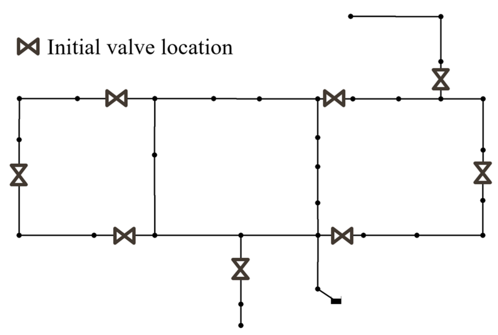
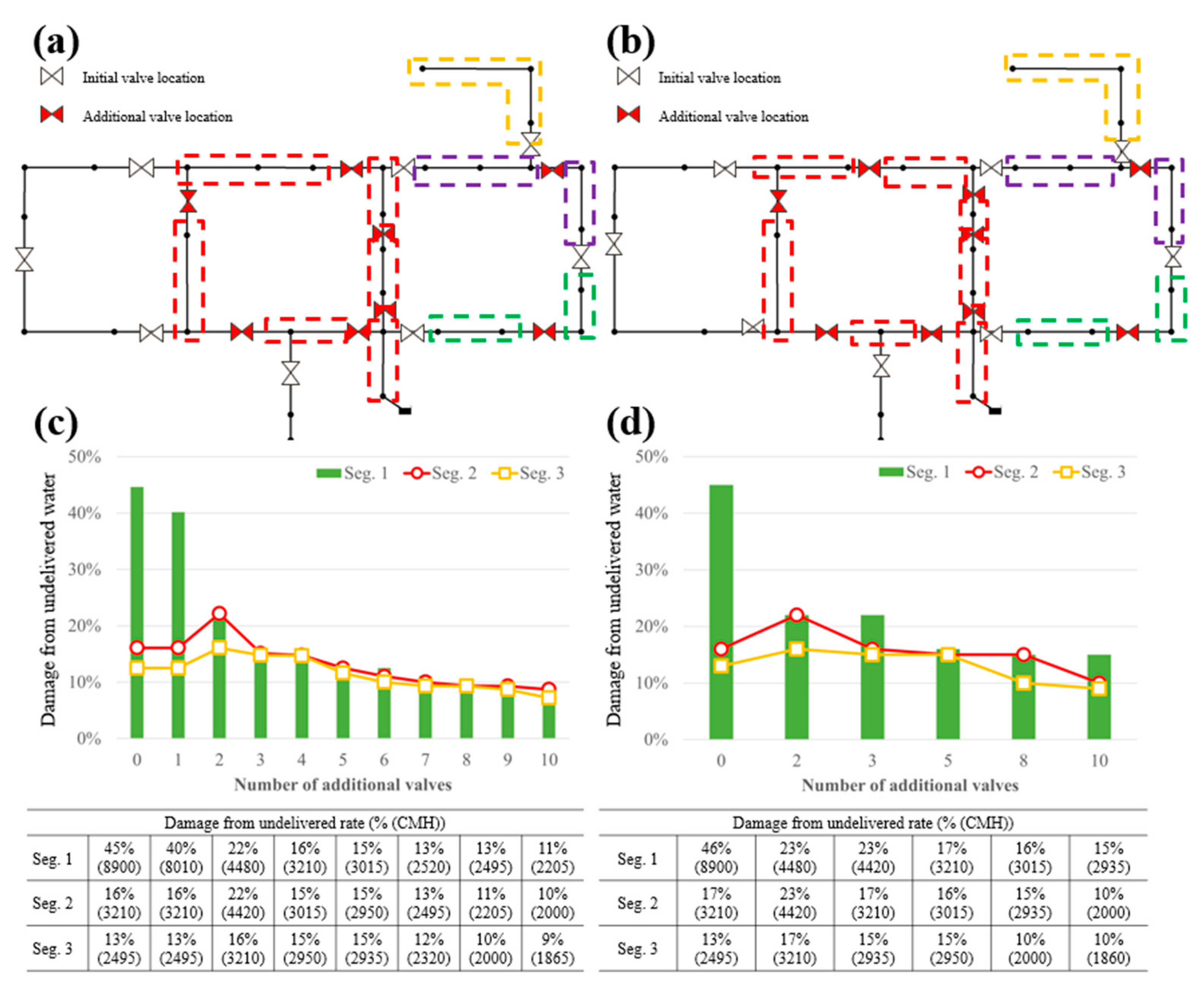
3.1.1. Benchmark Network: Hanoi Network
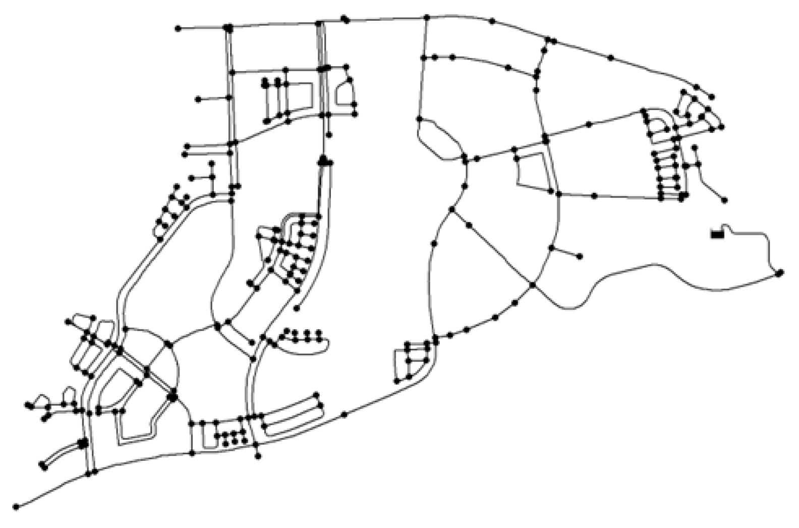
3.1.2. Real-World Network: J-City Network
4. Conclusions
Author Contributions
Funding
Data Availability Statement
Conflicts of Interest
References
- Olsson, G. Urban water supply automation–today and tomorrow. AQUA—Water Infrastruct. Ecosyst. Soc. 2021, 70, 420–437. [Google Scholar] [CrossRef]
- Wakode, H.B. Analysis of Urban Growth and Assessment of Impact of Urbanization on Water Resources: A Case Study of Hyderabad, India. Ph.D. Thesis, RWTH Aachen University, Aachen, Germany, 2016. [Google Scholar]
- Hashimoto, T.; Stedinger, J.R.; Loucks, D.P. Reliability, resiliency, and vulnerability criteria for water resource system performance evaluation. Water Resour. Res. 1982, 18, 14–20. [Google Scholar] [CrossRef] [Green Version]
- Lansey, K. Sustainable, robust, resilient, water distribution systems. In Proceedings of the WDSA 2012: 14th Water Distribution Systems Analysis Conference, Adelaide, South Australia, 24–27 September 2012; pp. 1–18. [Google Scholar]
- Walski, T.M. Water distribution valve topology for reliability analysis. Reliab. Eng. Syst. Saf. 1993, 42, 21–27. [Google Scholar] [CrossRef]
- Jun, H.D. Isolating subsystems by valves in a water distribution system and evaluating the system performance. J. Korea Water Resour. Assoc. 2005, 38, 585–593. [Google Scholar] [CrossRef]
- Jun, H.D.; Park, J.I.; Baek, C.W.; Kim, J.H. A segment-based minimum cutset method for estimating the reliability of water distribution systems. J. Korea Water Resour. Assoc. 2007, 40, 735–742. [Google Scholar] [CrossRef]
- Jun, H.; Loganathan, G.V. Valve-controlled segments in water distribution systems. J. Water Resour. Plan. Manag. 2007, 133, 145–155. [Google Scholar] [CrossRef]
- Choi, Y.H.; Jung, D.; Jun, H.; Kim, J.H. Improving water distribution systems robustness through optimal valve installation. Water 2018, 10, 1223. [Google Scholar] [CrossRef] [Green Version]
- Lim, G.; Kang, D. Optimal placement of isolation valves in water distribution networks based on segment analysis. J. Korea Water Resour. Assoc. 2019, 52, 291–300. [Google Scholar]
- Creaco, E.; Franchini, M.; Alvisi, S. Optimal placement of isolation valves in water distribution systems based on valve cost and weighted average demand shortfall. Water Resour. Manag. 2010, 24, 4317–4338. [Google Scholar] [CrossRef]
- Giustolisi, O.; Savic, D. Identification of segments and optimal isolation valve system design in water distribution networks. Urban Water J. 2010, 7, 1–15. [Google Scholar] [CrossRef]
- Rossman, L.A.; Woo, H.; Tryby, M.; Shang, F.; Janke, R.; Haxton, T. EPANET 2.2 User’s Manual; Water infrastructure division. Center for Environmental Solutions and Emergency Response. U.S. Environmental Protection Agency (EPA): Cincinnati, OH, USA, 2020. [Google Scholar]
- MATLAB, Starting. Matlab; The MathWorks: Natick, MA, USA, 2012. [Google Scholar]
- Eliades, D.G.; Kyriakou, M.; Vrachimis, S.; Polycarpou, M.M. EPANET-MATLAB Toolkit: An open-source software for interfacing EPANET with MATLAB. In Proceedings of the 14th International Conference on Computing and Control for the Water Industry (CCWI), Amsterdam, The Netherlands, 7–9 November 2016; pp. 1–8. [Google Scholar]
- Ozger, S.; Mays, L.W. Optimal location of isolation valves in water distribution systems: A reliability/optimization approach. Water Resour. Syst. Manag. Tools 2004, 7, 4. [Google Scholar]
- Geem, Z.W.; Kim, J.H.; Loganathan, G.V. A new heuristic optimization algorithm: Harmony search. Simulation 2001, 76, 60–68. [Google Scholar] [CrossRef]
- Fujiwara, O.; Khang, D. A two-phase decomposition method for optimal design of looped water distribution networks. Water Resour. Res. 1990, 26, 539–549. [Google Scholar] [CrossRef]

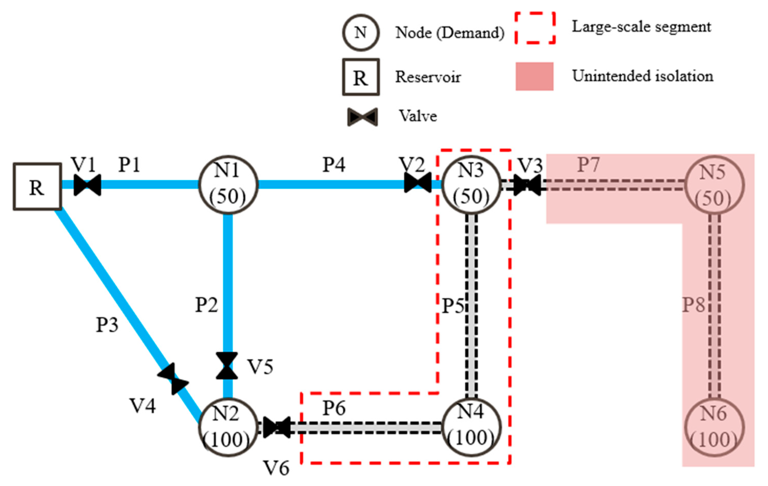




| Segment No. | Pipes | Nodes | Damage (CMH) | UI(CMH) |
|---|---|---|---|---|
| Seg. 1 | P1, P2, P4 | N1 | 50 | 0 |
| Seg. 2 | P5, P6 | N3, N4 | 150 | 150 |
| Seg. 3 | P7, P8 | N5, N6 | 150 | 0 |
| Seg. 4 | N2 | 50 | 0 | |
| Seg. 5 | P3 | 0 | 0 |
Disclaimer/Publisher’s Note: The statements, opinions and data contained in all publications are solely those of the individual author(s) and contributor(s) and not of MDPI and/or the editor(s). MDPI and/or the editor(s) disclaim responsibility for any injury to people or property resulting from any ideas, methods, instructions or products referred to in the content. |
© 2023 by the authors. Licensee MDPI, Basel, Switzerland. This article is an open access article distributed under the terms and conditions of the Creative Commons Attribution (CC BY) license (https://creativecommons.org/licenses/by/4.0/).
Share and Cite
Kim, M.J.; Choi, Y.H. Optimal Segmentation Approach for Reducing Water Outage Damage Considering Urbanization in Water Distribution Systems. Water 2023, 15, 2780. https://doi.org/10.3390/w15152780
Kim MJ, Choi YH. Optimal Segmentation Approach for Reducing Water Outage Damage Considering Urbanization in Water Distribution Systems. Water. 2023; 15(15):2780. https://doi.org/10.3390/w15152780
Chicago/Turabian StyleKim, Min Jun, and Young Hwan Choi. 2023. "Optimal Segmentation Approach for Reducing Water Outage Damage Considering Urbanization in Water Distribution Systems" Water 15, no. 15: 2780. https://doi.org/10.3390/w15152780
APA StyleKim, M. J., & Choi, Y. H. (2023). Optimal Segmentation Approach for Reducing Water Outage Damage Considering Urbanization in Water Distribution Systems. Water, 15(15), 2780. https://doi.org/10.3390/w15152780