Article

Effect of Gradation Characteristics and Particle Morphology on Internal Erosion of Sandy Gravels: A Large-Scale Experimental Study

1
School of Civil Engineering, Chongqing University, Chongqing 400045, China
2
Key Laboratory of New Technology for Construction of Cities in Mountain Area, Chongqing University, Chongqing 400045, China
3
Chengdu Engineering Corporation Limited, Power China, Chengdu 610072, China
*
Author to whom correspondence should be addressed.
Water 2023, 15(14), 2660; https://doi.org/10.3390/w15142660
Submission received: 8 June 2023 / Revised: 5 July 2023 / Accepted: 11 July 2023 / Published: 22 July 2023

Abstract

:
Internal erosion refers to the seepage-induced fine particle migration phenomenon in soil. Deep alluviums in valleys usually contain cohesionless gap-graded sandy gravels with poor internal stability. The construction of embankment dams on such alluviums could pose a high risk of internal erosion. This study systematically investigated the internal erosion of cohesionless gap-graded sandy gravels with an emphasis on the effects of gradation characteristics and particle morphology. A series of large-scale internal erosion tests were conducted on gap-graded sandy gravels with different gap ratios, fines contents, and coarse particle morphologies under the surcharge pressure of 1 MPa. The internal erosion characteristics, including soil permeability, eroded soil mass, and soil deformation during the erosion process were comparatively analyzed in combination with a meso-mechanism interpretation. The results show that the increase of the gap ratio can reduce the internal stability of soil and promote the mechanical instability. Fines content affected the permeability and internal stability of soil by altering the filling state of inter-granular pores and the constraints on fine particles. Coarse particles with higher roundness, sphericity, and smoothness can facilitate the movement of fine particles and promote the mechanical instability of the soil matrix.

1. Introduction

Sandy gravels are widely distributed in natural deep alluviums in valleys. For the gap-graded sandy gravels with relatively lower fine content, the soil might be internally unstable because of the following two mechanisms. Firstly, the force matrix is mainly composed of gravels, and sands are distributed in the pore channels within the gravels with little constraint stress [1]. Secondly, the constrictions in the pore channels are larger than some sands, allowing these sands to pass through the constrictions [2]. Under seepage conditions, sands can detach and migrate within the pore channels. This phenomenon is termed internal erosion [3]. If internal erosion induces the loss of a certain proportion of fine particles, the hydraulic and mechanical properties of the soil may be changed [4,5,6,7,8]. Internal erosion has been widely reported as a primary factor contributing to embankment dam accidents and failures [9]. With an increasing number of embankment dams being constructed on deep alluviums, it is of practical significance to deepen the cognition of internal erosion in sandy gravel alluviums.
Gap-graded sandy gravels can be regarded as a binary mixture of a coarse fraction and a fine fraction [10]. In the gradation of a binary mixture, in addition to the particle sizes, gap ratio G r and fines content F c are two further factors that determine the arrangement of the mixture’s fabric. The gap ratio is defined as the ratio between the minimum particle size of coarse fraction and the maximum particle size of fine fraction [11]. It can be used to quantify the ability of the coarse fraction to filtrate the fine fraction. The larger the gap ratio, the easier it is for the fine particles to infiltrate the constrictions within the coarse particles [2,11,12]. The fines content is usually defined as the ratio of the fine fraction mass to the total soil mass [13]. It has been found that the fines content has a strong relationship with the mesostructure of soil fabric [14], thus affecting the stress state on both coarse and fine fractions [1,15]. Another factor that cannot be reflected in the gradation but significantly influences the soil’s hydraulic and mechanical behavior is the particle morphology [16,17,18,19], which can be quantified by the dimensionless parameters, including sphericity, roundness, and smoothness [20].
In previous internal erosion studies, the effects of gap ratio [15,21], fines content [8,22,23,24], and particle morphology [25,26,27,28] on internal erosion have been investigated, and valuable insights into how these factors influence the erosion process have been provided. However, most of these experimental studies focused on silty sands or sandy gravels with gravels finer than 20 mm, owing to the size limitation of the permeameters. Additionally, the erosion tests in these studies were mainly conducted under a vertical seepage flow and a relatively lower confining stress. These valuable results can greatly improve the understanding of soil erosion in situations such as those of rainfall-induced infiltration in slope [29,30], or underground water level variation-induced erosion in the urban ground [31]; however, they should be used with caution when facing situations such as the internal erosion in deep sandy gravel alluvium foundation with large gravels, and those involving horizontal seepage flow and high overburden pressure. First, particle size is a dominant factor that influences the packing and flowability of granular material, as fine particles with different sizes can exhibit distinct cohesive effects [32]. Therefore, the erosion behavior between sandy gravels and silty sands might be different. It was found that the particle behavior during the migration and deposition varies with the particle size [33]. Second, even for specimens of the same gradation, the permeability and internal stability could be diverse, with different specimen sizes, and specimens of a larger scale were thus recommended for erosion tests [34,35]. Furthermore, the soil usually exhibits strong anisotropy, with the combination of the gravity effect, the direction of the seepage flow can affect the soil’s internal stability and erosion phenomena [36]. Moreover, numerous studies have demonstrated that both the stress state and stress magnitude can have a significant effect on internal stability, as well as the erosion-induced hydraulic and mechanical responses [37,38,39,40]. Recent numerical studies have further demonstrated that the directions of seepage flow and principal stress can influence the internal stability of the soil [41,42]. Currently, due to the scarcity of large-scale erosion apparatus in the past and the corresponding laborious operation, many internal erosion characteristics of sandy gravels under the aforementioned conditions were initially obtained by means of numerical simulations. Hence, a benchmark validation is necessary based on systematic experimental data.
This study aimed to investigate the effect of gradation characteristics and particle morphology on internal erosion characteristics, to better understand the behavior of gap-graded sandy gravels in deep alluviums. A novel erosion apparatus was used to test sandy gravels with different gap ratios, fines contents, and particle morphologies. The developments of soil permeability, fine particle loss and the consequent volumetric strain during the erosion process were summarized. Combined with the perspective of meso-changes in soil fabric, the influence of gradation characteristics and particle morphology on the internal erosion of sandy gravels was interpreted.

2. Methodology

2.1. Test Apparatus

Figure 1 schematically shows the apparatus used for the internal erosion tests. This large-scale high-pressure erosion apparatus was specially designed for the internal erosion study of sandy gravels under horizontal seepage flow and vertical overburden pressure. It is composed of a permeation box, a surcharge pressure loading system, a water supply system, an eroded soil collection system, and a flux measuring system. Here, a brief introduction to the key components is provided; readers interested in a more detailed description of the apparatus could refer to Wang et al. [39].
As illustrated in Figure 1, it can be noted that the valves for inflow and outflow are designed at the two sides of the permeation box, accordingly, the seepage direction in the permeation box is horizontal. The permeation box consists of three chambers, namely the inlet chamber, the specimen chamber, and the outlet chamber. These chambers are arranged sequentially along the seepage path and separated by two perforated plates. The inlet chamber is designed upstream of the specimen chamber to buffer the inflow from the head tank and apply a uniform water flow to the specimen. The size of the specimen chamber is 600 mm × 400 mm × 400 mm, thus it can be used to carry out seepage tests for sandy gravels with a particle size up to 80 mm. For the sealing of the specimen chamber and application of surcharge pressure, a specially designed movable ceiling cap is placed on the top of the specimen. The surcharge pressure loading system can provide a maximum surcharge pressure of 3.0 MPa on the specimen. Four linear variable differential transformers (LVDTs) are installed at the corners of the ceiling cap to continuously measure the settlement of the loading cap. By averaging the settlement data, the deformation of the specimen during the erosion process can be obtained.
During the erosion process, the fine particles in the specimens will be eroded out and migrate into the outlet chamber. The outlet chamber has a transparent window on the sidewall to facilitate the observation of erosion phenomena during the tests. A subsidence funnel is designed at the bottom of the outlet chamber to collect the eroded particles. A flushing valve is designed at the bottom of the subsidence funnel. By periodically opening the flushing valve, the collected fine particles can be obtained. A graduated cylinder and a triangular weir are set at the outlet of the outlet chamber to measure the flow rate, by which the soil permeability can be determined.

2.2. Test Materials

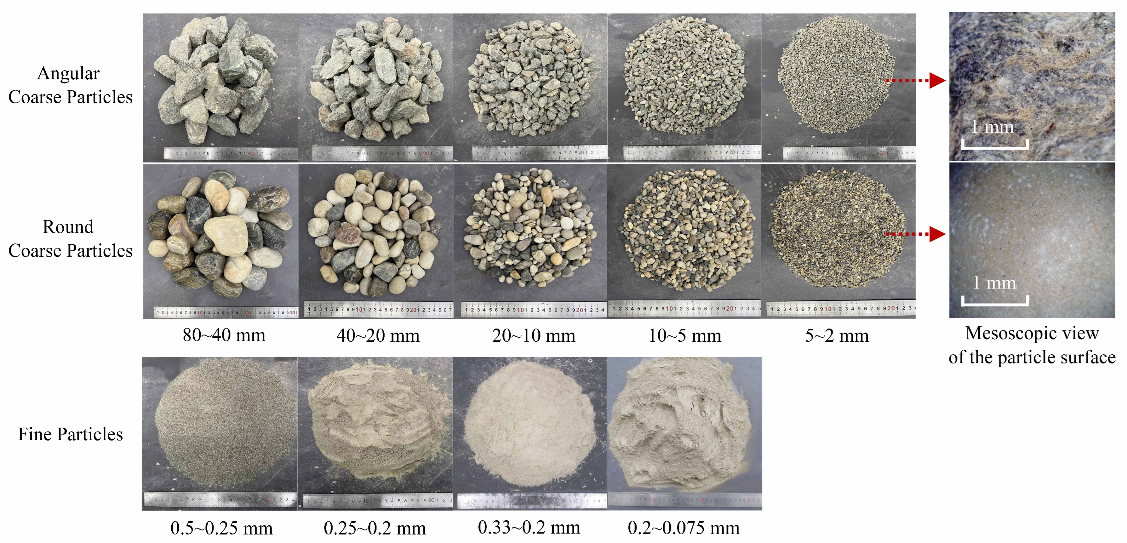
Figure 2 shows the test materials used in the test. The test materials were obtained from a sandy gravel alluvium of a dam foundation in China. In this study, a threshold size of 2 mm was used for dividing the test materials into a coarse fraction (>2 mm) and a fine fraction (<2 mm). In order to prepare gap-graded soil, the particles ranging from 0.5 to 2 mm were intentionally taken out, and the test materials were sieved into different fractions according to the particle size, as shown in Figure 2, for morphology parameters measurement and subsequent specimen preparation. Furthermore, the coarse particles were divided into a round fraction and an angular fraction according to the particle morphology.
First, to investigate the gap ratio effect on internal erosion, four gradations with different gap ratios were designed. In this study, the minimum particle size of the coarse fraction was kept consistent at 2 mm, by setting the maximum particle size of the fine fraction as 0.5, 0.33, 0.25 to 0.2 mm, four different gap ratios of 4, 6.7, 8, and 10 were obtained, respectively.
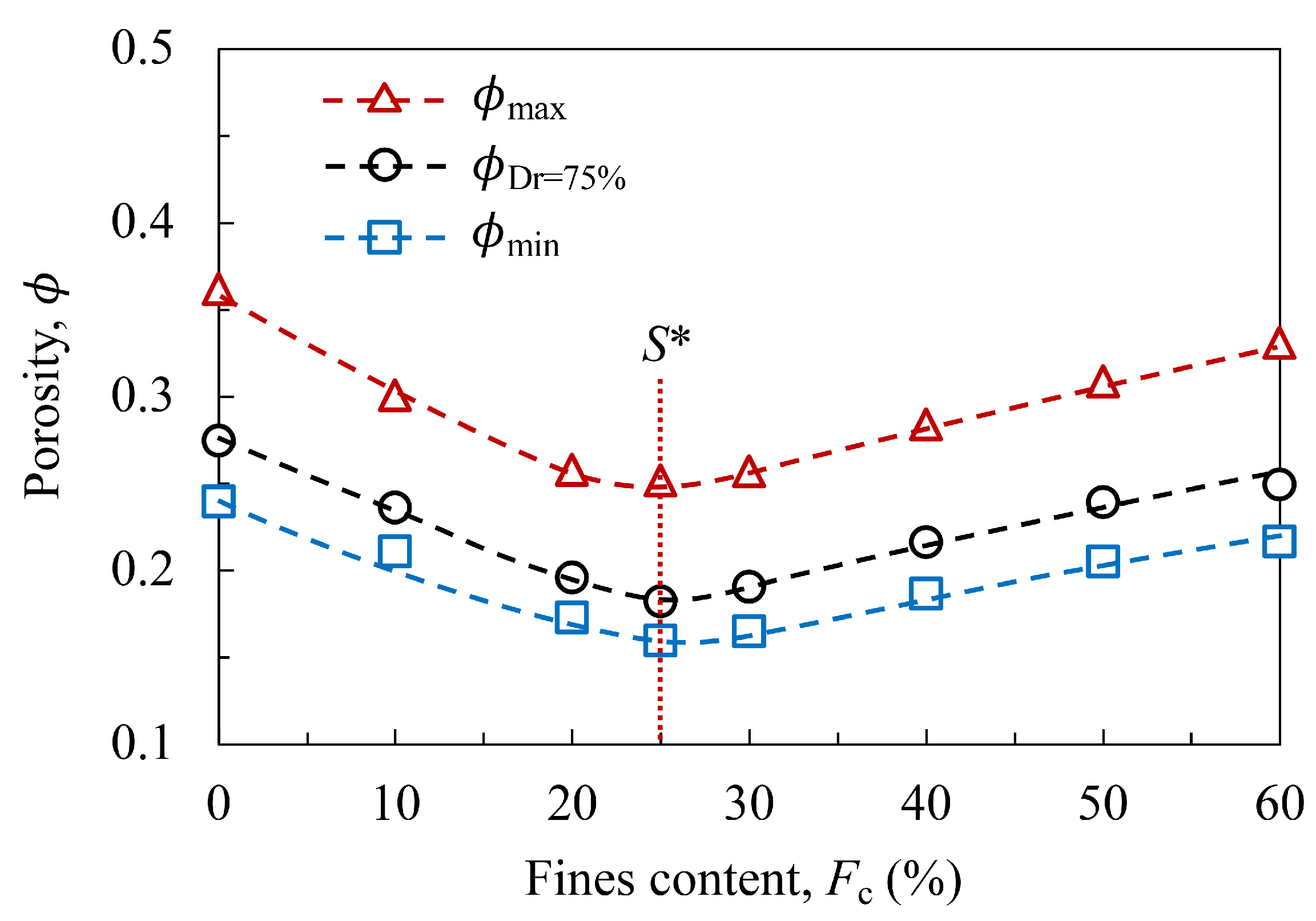
Second, to investigate the fines content effect on internal erosion, the gradation with a gap ratio of 8 was selected to produce gradations with different fines contents. Figure 3 shows the variation of porosity with fines content in the gap-graded soils. It can be seen that, for the soils at the relative densities of D r = 0 % , D r = 75 % , and D r = 100 % , the porosities all show a trend of decrease at first and increase later with the increasing fines content. The fines content corresponding to the minimum porosity is termed the critical fines content S * [4]. Studies have extensively demonstrated that three states can be found for the internal stability of soil according to the fines content: (1) when the fines content of the soil is less than S * , the inter-granular pores are under-filled with fine particles and the soil is prone to be internally unstable; (2) when the fines content is approximate to S * , the inter-granular pores are precisely-filled with fine particles and the soil is prone to be marginally stable; and (3) when the fines content is higher than S * , the inter-granular pores are over-filled with fine particles and the soil is prone to be internally stable [4,8,11,43,44]. It can be seen in the figure that the S * of the test soil is approximately 25%. Hence, three fines contents of 10%, 25%, and 40% were selected to produce gradations with different internal stability.
Third, to comparatively investigate the effect of particle morphology of the coarse particles on internal erosion, the gradation with gap ratio of 8 and fines content of 25% was employed. To quantify the particle morphology, the morphology parameters, including sphericity and roundness, of the coarse particles were measured. First, 50 particles were taken from each particle size fraction for photographing. Then, the software Image-Pro Plus 6.0 was employed to extract the boundary contour of each particle, so that the sphericity and roundness of each particle could be automatically analyzed. Finally, the values of all the particles in each fraction were averaged. The average values of all the particle size fractions are listed in Table 1. Clearly, both the sphericity and roundness of the particles in the round fraction are higher than those of the particles in the angular fraction.
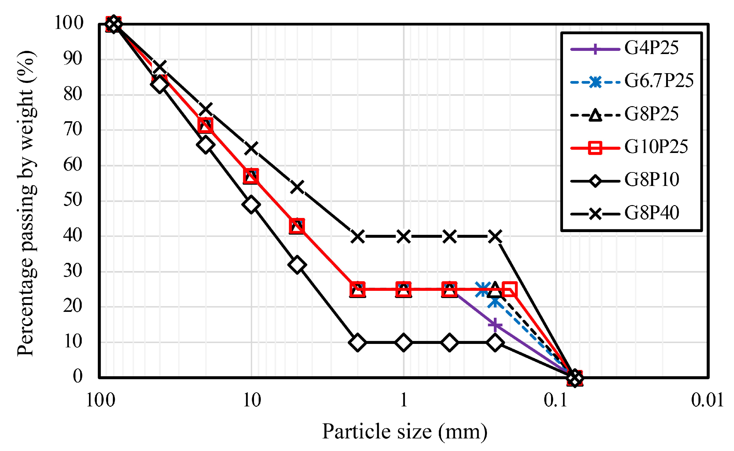
As shown in Figure 4, a total of six gradations were involved in this test, and the corresponding physical properties are given in Table 2. For the convenience of the description hereinafter, the specimen of each gradation is named using the combination of gap ratio, fines content, and particle morphology, i.e., G4P25A represents the specimen with a gap ratio of 4, a fines content of 25%, and the coarse fraction composed of angular particles. G8P25R represents the specimen with a gap ratio of 8, a fines content of 25%, and the coarse fraction composed of round particles. Furthermore, repeated tests were conducted on specimens G8P25A, G10P25A, and G8P25R, which involved different gradation characteristics and particle morphologies, in order to validate the reliability of the test results. The repeated specimens were named with the suffix r.

2.3. Specimen Preparation

There were three steps in specimen preparation: specimen compaction, surcharge pressure application, and specimen saturation. First, all of the specimens were compacted at a relative density D r of 75%. The required soil mass of the specimen was determined by the dry density and the specimen volume. The required soil mass of each particle size fraction was calculated according to the gradation presented in Figure 4. Subsequently, all the fractions were mixed with a water content of 1% and equally divided into four parts. These fractions were then compacted into the specimen chamber layer by layer to achieve the predetermined specimen height.
After the specimen was compacted, the ceiling cap was placed on the specimen and the LVDTs were installed. Then, the surcharge pressure was gradually increased to the designated value. For all of the specimens, the surcharge pressure was designated to 1 MPa. After that, the vent holes on the ceiling of the permeation box were opened and the inlet chamber and outlet chamber were slowly infused with water. When there were no air bubbles observed at the vent holes and the settlement of the ceiling cap stopped, the saturation was complete and the specimen was ready for the internal erosion test.

2.4. Test Scheme

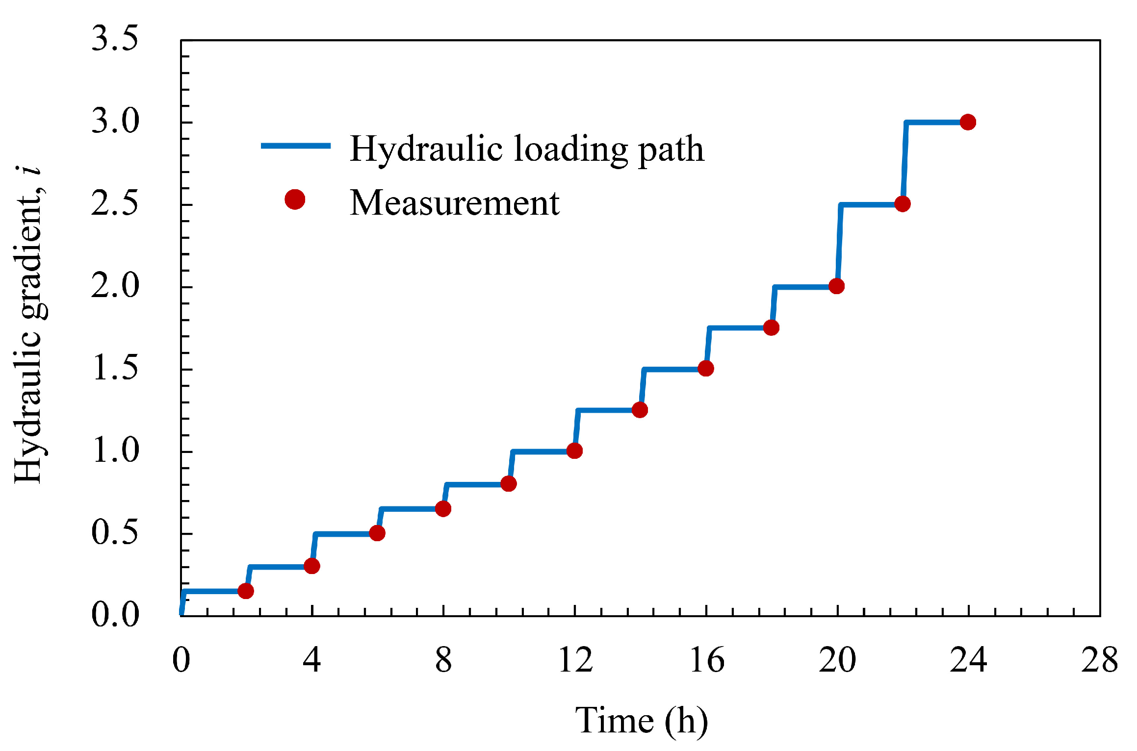
A stepwise increasing hydraulic gradient is usually adopted in the internal erosion test [4,37]. In this study, the hydraulic gradient imposed on the specimen can be precisely controlled by changing the height of the hand tank. Therefore, a stepwise increasing hydraulic gradient procedure, which ranges from 0.15 to 3.0, aiming to cover the general hydraulic gradients in situ, was designed. The time history of the imposed hydraulic gradient is shown in Figure 5. Each hydraulic gradient step is of a 2 h duration in order to ensure the erosion at each stage can reach a steady state (with no further observable particle being eroded out). The phenomena during the erosion process were continuously recorded, and the flow rate, eroded soil mass, and deformation of the specimen were measured at the end of each stage.

3. Test Results

3.1. Test Repeatability

To examine the reliability of the test results, the repeated test results of the gradations G8P25A, G10P25A, and G8P25R are comparatively analyzed. Figure 6 shows the change of hydraulic conductivity k , fines eroded ratio μ (the ratio of the accumulated eroded soil mass to the initial mass of fine fraction), and volumetric strain ε v (the ratio of the loading cap settlement to the initial specimen height) during the tests of the three gradations. It can be seen that for each repeated test, the development of all the physical quantities showed a similar trend. Table 3 gives the typical results of all the specimens before and after the tests. As can be seen, the initial hydraulic conductivities of the specimens in each repeated test were very close, indicating that the specimen preparation had a good consistency. The critical hydraulic gradient at which remarkable changes in the hydraulic or mechanical properties of the soil occur can be referred to as the progression hydraulic gradient i p [39]. For the identified progression hydraulic gradient during the test, there was a slight difference in the repeated tests of G8P25A and G10P25A, while they were still in the adjacent hydraulic gradient steps. For the specimens of G8P25R, the progression hydraulic gradient showed an identical value i p = 1.25. Furthermore, the final hydraulic conductivities of the specimens in each repeated test were very close. For the final fines eroded ratio at the end of the test, the deviations between the repeated tests of G8P25A, G10P25A, and G8P25R were 12.1%, 9.3%, and 5.2%, respectively. Moreover, it was found that for all the tests, there were rarely particles coarser than 0.5 mm in the eroded-out soils. For the volumetric strain at the end of the test, the deviations between the repeated tests of G8P25A, G10P25A, and G8P25R were 19.9%, 6.3%, and 8.6%, respectively. Considering the uncertainties in the specimen preparation and erosion process, these results imply a good repeatability of the erosion test.

3.2. Effect of Gap Ratio

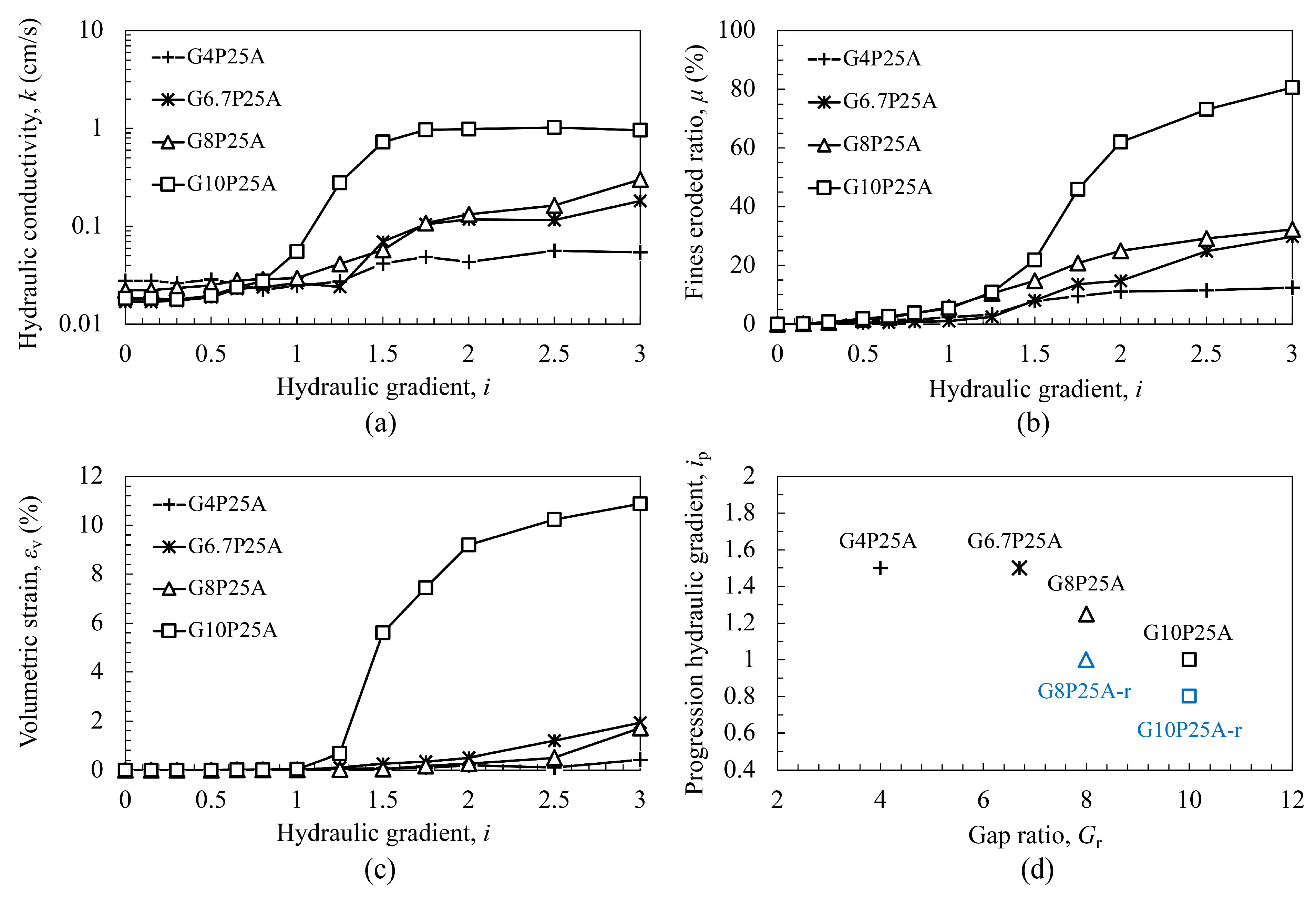
Figure 7 shows the internal erosion characteristics for the specimens with different gap ratios ( G r = 4, 6.7, 8, and 10) but the same fines content ( F c = 25%) and particle morphology (granular coarse particles). Figure 7a shows the curves of hydraulic conductivity with the development of hydraulic gradient. It can be seen that the initial hydraulic conductivities of the specimens were close, indicating that the gap ratio did not affect the initial permeability of the soil. Furthermore, it can be seen that all of the specimens showed an obvious increase in hydraulic conductivity during the erosion process, and the increment increased with the increase of gap ratio.
Figure 7b shows the curves of the fines eroded ratio with the development of the hydraulic gradient. As can be seen, the specimens with a higher gap ratio exhibited a higher fines eroded ratio during the test, indicating that the increase of the gap ratio can promote the loss of fine particles. In this study, several mechanisms may be responsible for volume change in soil: (1) a reduction in fine particle volume and a rearrangement of skeleton particles induced by fine particle loss; (2) a rearrangement of skeleton particles induced by the seepage force which is perpendicular to the principal stress; and (3) a reduction in strength of soils under the effects of long-term seepage. It can be seen in Figure 7c that the trend of volumetric strain was similar to that of the fines eroded ratio. As it is difficult to quantify the contribution of each mechanism to the volumetric strain, in this study we deemed the loss of fine particles to be the dominant mechanism affecting it.
Figure 7d shows the relationship of the progression hydraulic gradient with the gap ratio. It can be seen that the hydraulic gradient decreased with the increase of gap ratio. Combining the aforementioned results, we see that an increase in gap ratio can reduce the internal stability of the soil. This phenomenon is consistent with that observed in the numerical studies based on the discrete element method [21,45].

3.3. Effect of Fines Content

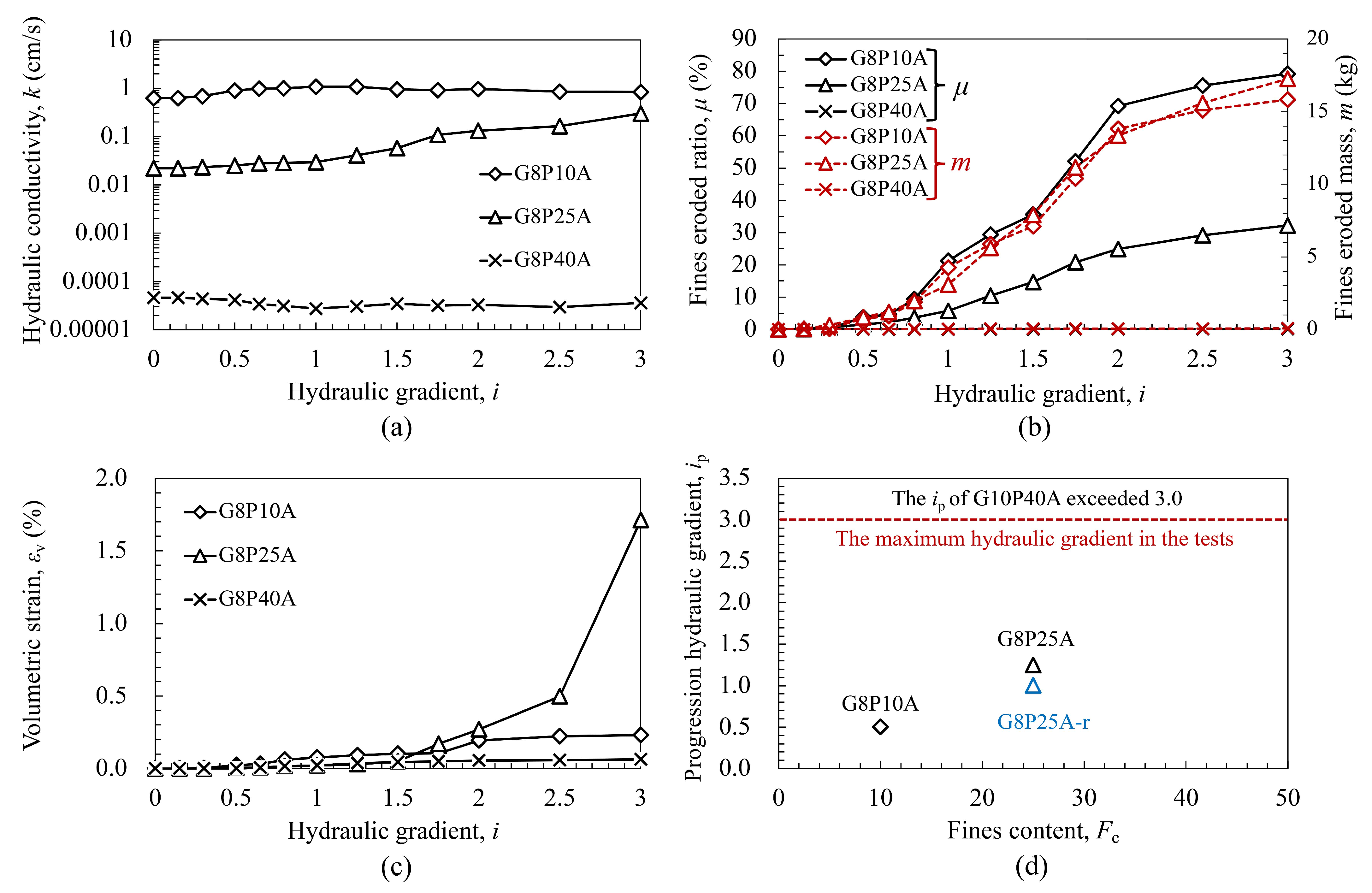
Figure 8 shows the internal erosion characteristics for the specimens with different fines contents ( F c = 10%, 25%, and 40%) but the same gap ratio ( G r = 8) and particle morphology (granular coarse particles). Figure 8a presents the development of hydraulic conductivity with the hydraulic gradient. It can be seen that there are considerable differences in the initial hydraulic conductivity of the three specimens. The initial hydraulic conductivity exhibited an increasing trend with the decrease of fines content. Furthermore, two different trends can be observed during the erosion process. For G8P25A, the hydraulic conductivity gradually increased from 2.22 × 10⁻² cm/s to 0.3 cm/s. In contrast, the hydraulic conductivities of G8P10A and G8P40A did not show obvious changes. Figure 8b gives the relationship between fines eroded ratio and hydraulic gradient as well as the relationship between fines eroded mass and hydraulic gradient. It can be seen that the fines eroded ratio of G8P10A was significantly higher than that of G8P25A, while, due to the different fines content, their fines eroded masses were close. However, the hydraulic conductivity development of the two specimens was different during the erosion process.
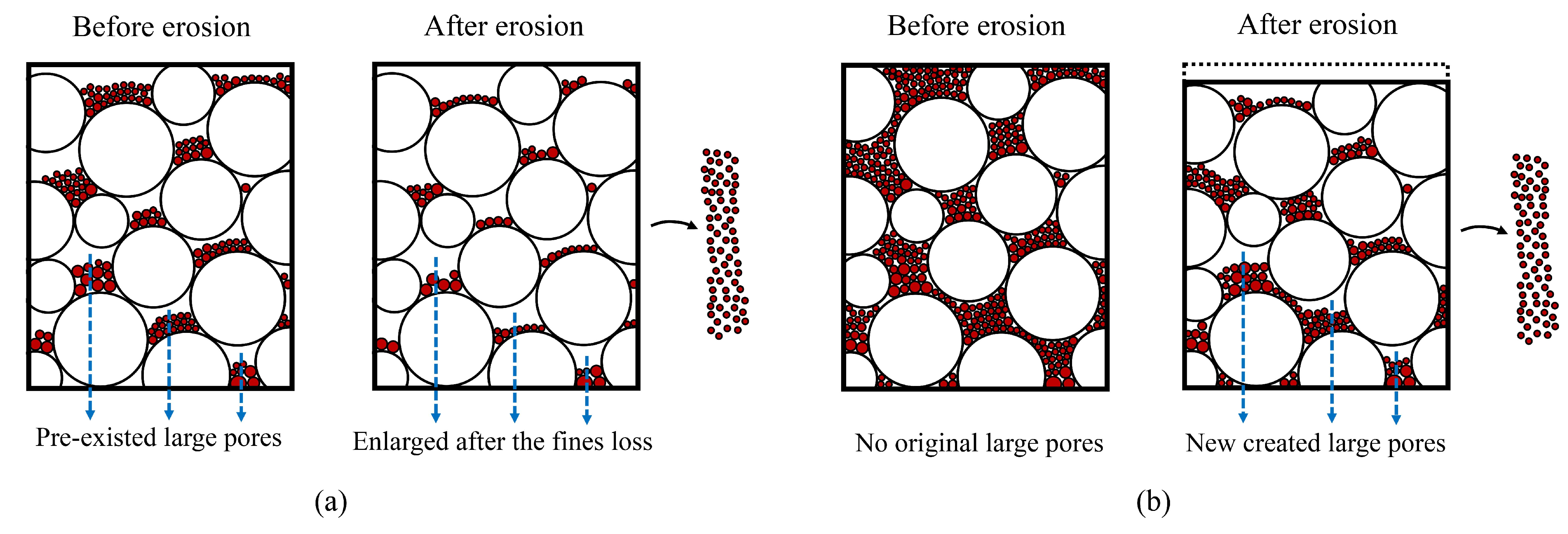
To better elaborate the mechanism of the distinct hydraulic responses in G8P10A and G8P25A, Figure 9 illustrates the mesoscopic particle arrangement of the two soils. It is known that the soil’s permeability is dominated by the preferential seepage path, and that the preferential seepage path is composed of the large pore channels in the soil. It can be seen that for G8P10A, the fine particles cannot completely fill the inter-granular pores within the coarse particles, thus leaving large pores in the soil. The higher initial porosity shown in Table 2 also demonstrates this meso-mechanism. Because the soil skeleton is dominated by coarse particles, the pre-existing large pore channels will be enlarged after most of the fine particles are eroded, while the morphology of the pore channels may not change significantly. In contrast, for G8P25A, the inter-granular pores are filled with fine particles and there is no large pore. The soil skeleton is composed of both coarse particles and fine particles [1]. The fine particle loss of the same volume can lead to a higher volumetric strain compared with G8P10A; hence, the increase in porosity is even smaller compared with G8P10A. However, the loss of this part of the fine particles can create unprecedented large pores in the inter-granular pores, therefore, the morphology of the pore channels is significantly changed and the soil’s permeability is consequently altered.
For G8P40A, the fine particles overfill the inter-granular pores and prompt some of the coarse particles float in the fine particle matrix [4,46]. Such a mesostructure leaves the fine particles under relatively higher effective stress, especially under the surcharge pressure of 1 MPa; thus, the fine particles are not easily eroded. Consequently, both the fines eroded ratio and volumetric strain were very small throughout the test. The slight decrease in hydraulic conductivity might be attributed to the blockage of pore channels caused by the particle clogging effect during the fine particle migration. Figure 8d shows the relationship between the progression hydraulic gradient and fines content, the corresponding values are also listed in Table 3. It can be observed that the progression hydraulic gradient increased with the increasing fines content, indicating that the higher fines content may enhance the internal stability of the soil.

3.4. Effect of Coarse Particle Morphology

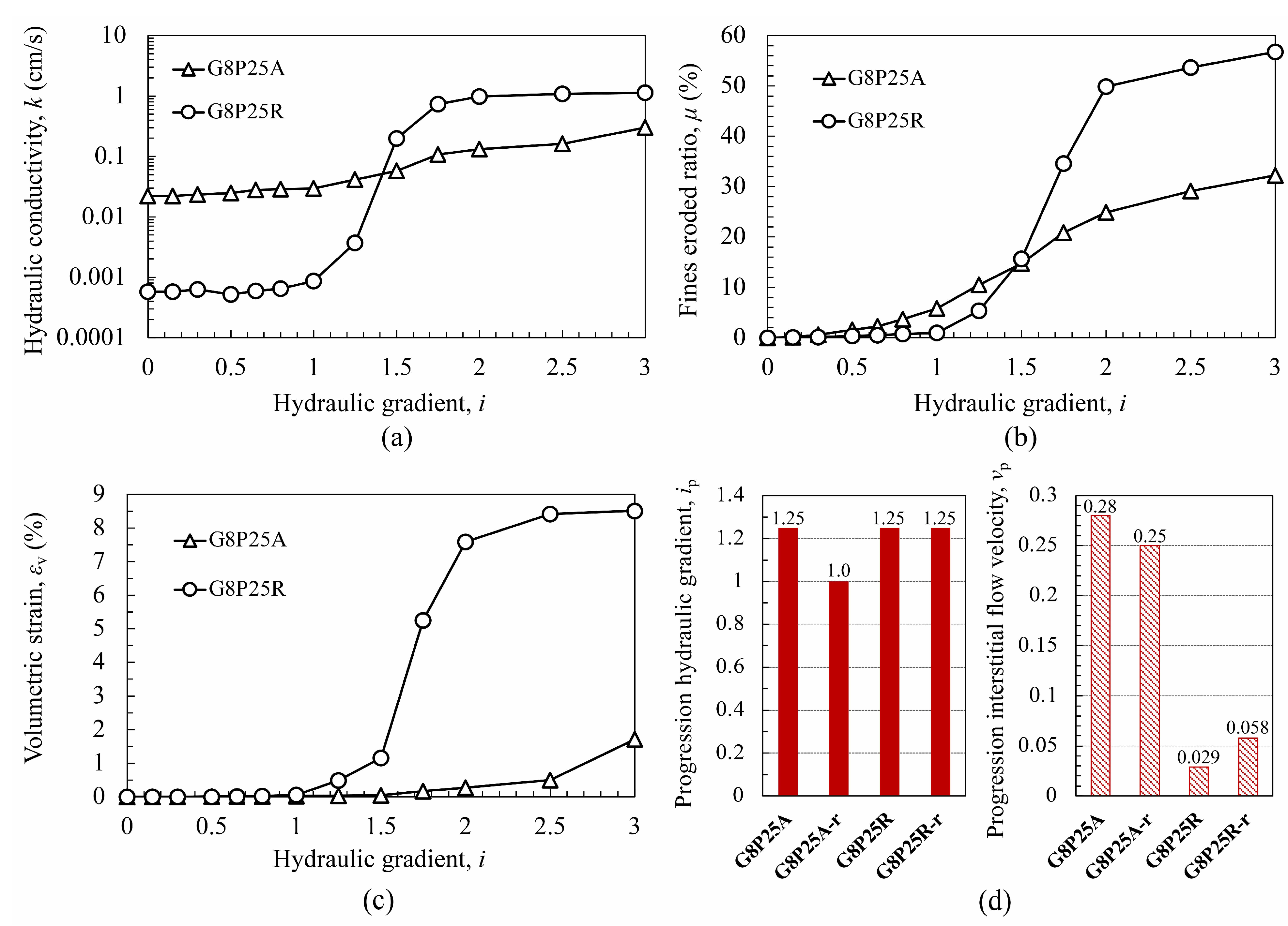
Figure 10 shows the internal erosion characteristics for the specimens with different coarse particle morphologies but the same gap ratio ( G r = 8) and fines content ( F c = 25%). Figure 10a shows the development of hydraulic conductivity with hydraulic gradient. Compared with specimen G8P25A with angular coarse particles, specimen G8P25R with round particles exhibited a lower initial hydraulic conductivity. It can be seen in Table 2 that, under the conditions of the same gradation and same relative density, the initial porosity of G8P25R ( ϕ 0 = 16.1%) is significantly lower than that of G8P25A ( ϕ 0 = 18.1%), which can be attributed to the cause of the difference in soil permeability. The phenomenon where increasing sphericity and roundness may reduce the void ratio and consequently the hydraulic conductivity has also been reported by Cho et al. [20] and Cherif et al. [19]. During the erosion process, the hydraulic conductivity of G8P25R increased from the k 0 = 5.79 × 10⁻⁴ cm/s to the k f = 1.13 cm/s, exceeding the hydraulic conductivity of G8P25A after the hydraulic gradient exceeded 1.5. This phenomenon can be attributed to the higher fines eroded ratio. As shown in Figure 10b, the fine eroded ratio of G8P25R reached 56.78% at the end of the test, almost double the value of 32.25% of G8P25A. Therefore, the change in hydraulic properties was larger, and the erosion-induced volumetric strain was more remarkable (as shown in Figure 10c).
Figure 10d contrasts the progression hydraulic gradient of specimens with different coarse particle morphologies. As can be seen, the progression hydraulic gradient was slightly higher with granular coarse particles, which was different from the observation by Maroof et al. [47]. Guo et al. [25] compared the fine particle erosion behavior under different flow velocities using a coupled CFD-DEM method. It was found that the critical velocity for ellipsoidal particles was higher than that for spherical particles. Deng et al. [40] also demonstrated that the critical interstitial flow velocity is an effective parameter to characterize the onset of internal instability. Hence, the critical interstitial flow velocities for the two soils were also compared. As there was only a limited fine particle loss at the progression hydraulic gradient, the porosity of the specimen was assumed to be equal to the initial porosity ϕ 0 , and the critical interstitial flow velocity v p at the progression hydraulic gradient, herein termed the progression interstitial flow velocity, can be calculated as follows:
v p = k i p ϕ 0
where k is the hydraulic conductivity at the progression hydraulic gradient. As shown in Figure 10d, the calculated progression interstitial flow velocities of G8P25A and G8P25A-r are 0.28 cm/s and 0.25 cm/s, respectively, while the progression interstitial flow velocities of G8P25R and G8P25R-r are 0.027 cm/s and 0.056 cm/s, respectively. Clearly, because the hydraulic conductivity at the progression hydraulic gradient of the specimens with round coarse particles was relatively lower, the progression interstitial flow velocity was consequently lower. This trend is consistent with the numerical observations in the research of Guo et al. [25].

3.5. Skeleton Stability Analysis

The relationship between fine particle loss and soil deformation is an important indicator, which can reflect the mechanical instability behavior during the erosion process [48]. To investigate the correlation between the volumetric strain and fine particle loss, a skeleton stability index, S s , is defined herein, which refers to the ratio of the volumetric strain and the volume fraction of the fines being eroded out. This index is given as:
S s = ε v μ F c 1 ϕ 0
Accordingly, three scenarios can be identified: (1) if S s < 1, this implies that the volumetric strain is lower than the reduction of eroded fines volume, and there is an increase in porosity; (2) if S s = 1, this implies that the fines volume reduction is entirely transferred into volumetric strain, and the porosity is hence kept constant; (3) if S s > 1, beyond the volumetric strain directly caused by fines loss, additional mechanical instability of the soil skeleton would occur. Consequently, there is a decrease in porosity.
Figure 11 gives the relationship between the skeleton stability index and hydraulic gradient, in which the values at the hydraulic gradient of i = 0.5, 1.0, 2.0, and 3.0 are illustrated. The skeleton stability indexes of all of the specimens each showed an increasing trend during the erosion process. Such a trend can be explained by the mesoscopic arrangement of particles in the soil matrix. In soil, the fine particles can generally be categorized into two groups based on their contribution to effective stress transfer: free fine particles and skeleton fine particles. The erodibility of fine particles is directly influenced by the effective stress applied to them [4]. The fine particles eroded at a relatively lower hydraulic gradient ( i = 0.5) were mainly the free fine particles that deposit in the pores with no or fewer constraints. The loss of this part of the fine particles does not considerably impact the stability of the soil skeleton. As the hydraulic gradient increases, more free fine particles, and even the skeleton fine particles with higher constraints, were progressively eroded out. The loss of this part of the fine particles not only reduces the mechanical stability of the soil skeleton but also directly changes the arrangement of the soil skeleton, thus leading to the acceleration of volumetric strain.
Moreover, it can be noted that there were differences in the development of the skeleton stability index in different specimens. Figure 11a shows the relationship between the skeleton stability index and hydraulic gradient in specimens with different gap ratios. The final skeleton stability index at the end of the test exhibited an increasing trend with the increase of gap ratio. Attempting to interpret this phenomenon, Figure 12 illustrates a conceptual model to show the mesoscopic fabric change in soils with different gap ratios during internal erosion. The two soils are assumed to have the same fines content and similar inter-granular pores filling states (precisely-filled) before erosion, and both lose half of the fine particles after erosion. It can be seen that, for both of the two soils, the coarse matrix exhibits a distortion after the loss of fine particles, and some of the remaining fine particles will get jammed within the coarse particles and form a new force chain. Here a distinction appears: for soil with a lower gap ratio, the relatively coarser fine particles are less likely to rearrange or segregate when subjected to seepage force and gravitational influences, the remainder of those in the inter-granular pores will restrict the distortion of the coarse matrix. In contrast, for soil with a higher gap ratio, the relatively finer fine particles are prone to segregate from the original inter-granular pores and infiltrate into the inter-granular pores below, while the fine particles remaining in the original inter-granular pores are prone to rearrange into a flat state. As a consequence, the coarse matrix can exhibit a larger distortion, and thus result in higher volumetric strain.
Figure 11b shows the relationship between the skeleton stability index and hydraulic gradient in specimens with different fines contents and coarse particle morphologies. It can be seen that the skeleton stability indexes are distinct among the specimens with different fines content. The specimens with a fines content of 25% have a skeleton stability index ranging from 0.2 to 0.8. In contrast, specimen G8P10A only has a skeleton stability index of 0.038, while the value in specimen G8P40A can reach 2.39. This phenomenon indicates that, in addition to the increasing proportion of skeleton fine particles that could directly induce higher skeleton deformation after the loss of the fines, the soil skeleton dominated by fine particles may exhibit a larger distortion and rearrange into a denser state. Meanwhile, it shows that only the skeleton stability index of G8P40A is higher than 1, indicating that only the porosity of G8P40A decreased during the erosion process. Such a phenomenon further explains the decrease in hydraulic conductivity illustrated in Figure 8a.
It can also be found in Figure 11b that the skeleton stability index was higher in the specimens with round coarse particles. It has been reported that, with the increase of particle angularity, the increase in interlocking effect can lead to a higher internal friction angle, thus increasing the soil’s shear strength [49]. Meanwhile, as can be seen in the pictures displaying the mesoscopic view of the particle surface in Figure 2, the roughness of the angular particle is clearly higher than that of the round particle. The higher particle roughness can further increase the interparticle friction [50]. This therefore raises the notion that, even in soils with the same gradation, different coarse particle morphologies can lead to huge distinctions in erosion-induced mechanical instability behavior.

4. Conclusions

A series of internal erosion tests were conducted on cohesionless gap-graded sandy gravels using a large-scale high-pressure erosion apparatus. The effects of different gap ratios, fines contents, and coarse particle morphologies on the internal erosion characteristics were systematically investigated. Based on the test results and meso-mechanism analysis, the following conclusions can be drawn:
(1)
The gap ratio can impact both the internal stability and mechanical stability of the soil. The increase in gap ratio not only reduced the progression hydraulic gradient, but also promoted the fine particle erosion process and the consequent permeability increase and volumetric strain. Moreover, a positive correlation was shown between the gap ratio and the skeleton stability index, indicating that soil with a higher gap ratio is more likely to suffer mechanical instability during the erosion process.
(2)
The fines content influences the filling state of inter-granular pores and the transfer of effective stress on fine particles, thereby affecting the permeability and internal stability of the soil. The soil showed a decreasing trend in the hydraulic conductivity while an increasing trend in the progression hydraulic gradient with the increase of fines content. Additionally, it was found that the increase in permeability was not directly related to the increase in porosity but might be highly related to the change in the pore channels morphology.
(3)
The morphology of coarse particles is an influential factor in determining the internal erosion characteristics. The increase in roundness, sphericity, and smoothness can reduce the interlocking effect within coarse particles, which results in two consequences. First, it facilitates the movement of fine particles. The specimens with round coarse particles showed a lower progression interstitial flow velocity and a higher fines eroded ratio compared with the specimens with granular coarse particles. Second, it prompts the soil matrix to reach a denser packing state. The specimens with round coarse particles not only showed a lower porosity and permeability after the specimen preparation, but also showed a higher skeleton stability index during the erosion process.

Author Contributions

Project administration, funding acquisition, W.J. and G.W.; methodology, G.W., Z.D. and X.C.; formal analysis, X.C., Z.D. and G.W.; investigation, X.C. and Z.D.; writing—original draft preparation, Z.D., X.C. and G.W.; writing—review and editing, Z.D., X.C. and G.W. All authors have read and agreed to the published version of the manuscript.

Funding

This research was supported by the National Natural Science Foundation of China (Grant No. 52079012) and the Natural Science Foundation of Chongqing (Grant No. cstc2021jcyj- msxmX0598).

Data Availability Statement

The data presented in this study are available on request from the corresponding author.

Conflicts of Interest

The authors declare no conflict of interest.

References

  1. Shire, T.; O’Sullivan, C.; Hanley, K.J.; Fannin, R.J. Fabric and effective stress distribution in internally unstable soils. J. Geotech. Geoenviron. Eng. 2014, 140, 04014072. [Google Scholar] [CrossRef] [Green Version]
  2. Kenney, T.C.; Lau, D. Internal stability of granular filters. Can. Geotech. J. 1985, 22, 215–225. [Google Scholar] [CrossRef]
  3. Fell, R.; Fry, J.J. State of the art on the likelihood of internal erosion of dams and levees by means of testing. In Erosion in Geomechanics Applied to Dams and Levees; Bonelli, S., Ed.; Wiley: London, UK, 2013; pp. 1–99. [Google Scholar] [CrossRef]
  4. Skempton, A.W.; Brogan, J.M. Experiments on piping in sandy gravels. Géotechnique 1994, 44, 449–460. [Google Scholar] [CrossRef]
  5. Hicher, P.Y. Modelling the Impact of Particle Removal on Granular Material Behaviour. Géotechnique 2013, 63, 118–128. [Google Scholar] [CrossRef] [Green Version]
  6. Benamar, A.; Correia dos Santos, R.N.; Bennabi, A.; Karoui, T. Suffusion evaluation of coarse-graded soils from Rhine dikes. Acta Geotech. 2019, 14, 815–823. [Google Scholar] [CrossRef]
  7. Prasomsri, J.; Takahashi, A. Experimental study on suffusion under multiple seepages and its impact on undrained mechanical responses of gap-graded soil. Soils Found. 2021, 61, 1660–1680. [Google Scholar] [CrossRef]
  8. Deng, Z.; Wang, G.; Jin, W. Mesostructural mechanism of hydraulic gradient fluctuations affecting internal instability using transparent soil. Geotech. Test. J. 2022, 45, 1054–1069. [Google Scholar] [CrossRef]
  9. Foster, M.; Fell, R.; Spannagle, M. The statistics of embankment dam failures and accidents. Can. Geotech. J. 2000, 37, 1000–1024. [Google Scholar] [CrossRef]
  10. Lade, P.V.; Liggio, C.D.; Yamamuro, J.A. Effects of Non-plastic Fines on Minimum and Maximum Void Ratios of Sand. Geotech. Test. J. 1998, 21, 336–347. [Google Scholar] [CrossRef]
  11. Chang, D.S.; Zhang, L.M. Extended internal stability criteria for soils under seepage. Soils Found. 2013, 53, 569–583. [Google Scholar] [CrossRef] [Green Version]
  12. Kezdi, A. Soil Physics: Selected Topics; Elsevier Scientific: Essex, UK, 1979. [Google Scholar]
  13. Richards, K.S.; Reddy, K.R. Experimental investigation of initiation of backward erosion piping in soils. Géotechnique 2012, 62, 933–942. [Google Scholar] [CrossRef] [Green Version]
  14. Cubrinovski, M.; Ishihara, K. Maximum and Minimum Void Ratio Characteristics of Sands. Soils Found. 2002, 42, 65–78. [Google Scholar] [CrossRef] [Green Version]
  15. Sufian, A.; Artigaut, M.; Shire, T.; O’Sullivan, C. Influence of Fabric on Stress Distribution in Gap-Graded Soil. J. Geotech. Geoenviron. Eng. 2021, 147, 04021016. [Google Scholar] [CrossRef]
  16. Göktepe, B.; Sezer, A. Effect of particle shape on density and permeability of sands. Proc. Inst. Civil Eng.-Geotechn. Eng. 2010, 163, 307–320. [Google Scholar] [CrossRef]
  17. Cabalar, A.F.; Akbulut, N. Effects of the particle shape and size of sands on the hydraulic conductivity. Acta Geotech. Slov. 2016, 13, 83–93. [Google Scholar]
  18. Taiba, A.C.; Mahmoudi, Y.; Belkhatir, M.; Schanz, T. Experimental Investigation into the Influence of Roundness and Sphericity on the Undrained Shear Response of Silty Sand Soils. Geotech. Test. J. 2018, 41, 619–633. [Google Scholar] [CrossRef]
  19. Cherif Taiba, A.; Mahmoudi, Y.; Hazout, L.; Belkhatir, M.; Baille, W. Evaluation of hydraulic conductivity through particle shape and packing density characteristics of sand–silt mixtures. Mar. Georesour. Geotech. 2019, 37, 1175–1187. [Google Scholar] [CrossRef]
  20. Cho, G.C.; Dodds, J.; Santamarina, J.C. Particle Shape Effects on Packing Density, Stiffness, and Strength: Natural and Crushed Sands. J. Geotech. Geoenviron. Eng. 2006, 132, 591–602. [Google Scholar] [CrossRef] [Green Version]
  21. Nie, Z.; Zhu, Y.; Zou, J.; Gong, J.; Liu, S. DEM study of the microscopic characteristics and internal stability of binary mixtures. Powder Technol. 2019, 352, 314–324. [Google Scholar] [CrossRef]
  22. Ke, L.; Takahashi, A. Experimental Investigations on Suffusion Characteristics and Its Mechanical Consequences on Saturated Cohesionless Soil. Soils Found. 2014, 54, 713–730. [Google Scholar] [CrossRef] [Green Version]
  23. Liang, Y.; Yeh, T.C.J.; Zha, Y.; Wang, J.; Liu, M.; Hao, Y. Onset of suffusion in gap-graded soils under upward seepage. Soils Found. 2017, 57, 849–860. [Google Scholar] [CrossRef]
  24. Cao, Z.; Sun, W.; Xie, Q.; Wu, Z.; Fu, X.; Fumagalli, A.; Tian, D.; Liang, L. Fluid–solid coupled model for the internal erosion of gap-graded soil–rock mixtures with different fines contents: Its verification and application. Hydrol. Processes 2022, 36, 14677. [Google Scholar] [CrossRef]
  25. Guo, Y.; Yang, Y.; Yu, X. Influence of particle shape on the erodibility of non-cohesive soil: Insights from coupled CFD–DEM simulations. Particuology 2018, 39, 21–24. [Google Scholar] [CrossRef]
  26. Nie, Z.; Fang, C.; Gong, J.; Yin. Z. Exploring the effect of particle shape caused by erosion on the shear behaviour of granular materials via the DEM. Int. J. Solids Struct. 2020, 202, 1–11. [Google Scholar] [CrossRef]
  27. Xiong, H.; Wu, H.; Bao, X.; Fei, J. Investigating effect of particle shape on suffusion by CFD-DEM modeling. Constr. Build Mater. 2021, 289, 123043. [Google Scholar] [CrossRef]
  28. Wang, T.; Zhang, F.; Zheng, W. Suffusion of Gap-Graded Soil with Realistically Shaped Coarse Grains: A DEM–DFM Numerical Study. Int. J. Geomech. 2023, 23, 04022247. [Google Scholar] [CrossRef]
  29. Cho, S.E.; Lee, S.R. Instability of unsaturated soil slopes due to infiltration. Comput. Geotech. 2001, 28, 185–208. [Google Scholar] [CrossRef]
  30. Zhang, L.; Wu, F.; Zhang, H.; Zhang, L.; Zhang, J. Influences of internal erosion on infiltration and slope stability. Bull. Eng. Geol. Environ. 2017, 78, 1–13. [Google Scholar] [CrossRef]
  31. Sterpi, D. Effects of the erosion and transport of fine particles due to seepage flow. Int. J. Geomech. 2003, 3, 111–122. [Google Scholar] [CrossRef]
  32. Elekes, F.; Parteli, E.J.R. An expression for the angle of repose of dry cohesive granular materials on Earth and in planetary environments. Proc. Natl. Acad. Sci. USA 2021, 118, e2107965118. [Google Scholar] [CrossRef]
  33. Torfs, H.; Mitchener, H.; Huysentruyt, H.; Toorman, E. Settling and consolidation of mud/sand mixtures. Coast. Eng. 1996, 29, 27–45. [Google Scholar] [CrossRef]
  34. Zhang, J.F.; Ding, P.Z.; Zhang, W.; Hu, Z.J. Studies of permeability and seepage deformation characteristics of cushion material for Shuibuya concrete faced rockfill dam. Rock Soil Mech. 2009, 30, 3145–3150. [Google Scholar] [CrossRef]
  35. Zhong, C.H.; Le, V.T.; Bendahmane, F.; Marot, D.; Yin, Z.Y. Investigation of spatial scale effects on suffusion susceptibility. J. Geotech. Geoenviron. Eng. 2018, 144, 10. [Google Scholar] [CrossRef]
  36. Pachideh, V.; Hosseini, S. A new physical model for studying flow direction and other influencing parameters on the internal erosion of soils. Geotech. Test. J. 2019, 42, 1431–1456. [Google Scholar] [CrossRef]
  37. Chang, D.S.; Zhang, L.M. Critical Hydraulic Gradients of Internal Erosion under Complex Stress States. J. Geotech. Geoenviron. Eng. 2013, 139, 1454–1467. [Google Scholar] [CrossRef]
  38. Jin, W.; Deng, Z.; Wang, G.; Zhang, D.; Wei, L. Internal Erosion Experiments on Sandy Gravel Alluvium in an Embankment Dam Foundation Emphasizing Horizontal Seepage and High Surcharge Pressure. Water 2022, 14, 3285. [Google Scholar] [CrossRef]
  39. Wang, G.; Deng, Z.Z.; Yang, J.; Chen, X.S.; Jin, W. A large-scale high-pressure erosion apparatus for studying internal erosion in gravelly soils under horizontal seepage flow. Geotech. Test. J. 2022, 45, 1037–1053. [Google Scholar] [CrossRef]
  40. Deng, Z.; Wang, G.; Jin, W.; Tang, N.; Ren, H.; Chen, X. Characteristics and quantification of fine particle loss in internally unstable sandy gravels induced by seepage flow. Eng. Geol. 2023, 321, 107150. [Google Scholar] [CrossRef]
  41. Wautier, A.; Bonelli, S.; Nicot, F. DEM investigations of internal erosion: Grain transport in the light of micromechanics. Int. J. Numer. Anal. Met. 2019, 43, 339–352. [Google Scholar] [CrossRef] [Green Version]
  42. Liu, Y.J.; Wang, L.Z.; Yin, Z.Y.; Hong, Y. A coupled CFD-DEM investigation into suffusion of gap-graded soil considering anisotropic stress conditions and flow directions. Acta Geotech. 2022, 18, 3111–3132. [Google Scholar] [CrossRef]
  43. Fannin, R.J.; Slangen. P. On the Distinct Phenomena of Suffusion and Suffosion. Geotech. Lett. 2014, 4, 289–294. [Google Scholar] [CrossRef]
  44. Ahmadi, M.; Shire, T.; Mehdizadeh, A.; Disfani, M.M. DEM modelling to assess internal stability of gap-graded assemblies of spherical particles under various relative densities, fine contents and gap ratios. Comput. Geotech. 2020, 126, 103710. [Google Scholar] [CrossRef]
  45. Shire, T.; O’Sullivan, C. Micromechanical assessment of an internal stability criterion. Acta Geotech. 2013, 8, 81–90. [Google Scholar] [CrossRef] [Green Version]
  46. Tian, D.; Xie, Q.; Fu, X.; Zhang, J. Experimental study on the effect of fine contents on internal erosion in natural soil deposits. Bull. Eng. Geol. Environ. 2020, 79, 4135–4150. [Google Scholar] [CrossRef]
  47. Maroof, A.; Mahboubi, A.; Noorzad, A. Particle Shape Effect on Internal Instability of Cohesionless Soils. In Proceedings of the 10th International Conference on Scour and Erosion (ICSE-10), Arlington, VA, USA, 18–21 October 2021. [Google Scholar]
  48. Wautier, A.; Bonelli, S.; Nicot, F. Rattlers’ contribution to granular plasticity and mechanical stability. Int. J. Plast. 2019, 112, 172–193. [Google Scholar] [CrossRef] [Green Version]
  49. Shinohara, K.; Oida, M.; Golman, B. Effect of Particle Shape on Angle of Internal Friction by Triaxial Compression Test. Powder Technol. 2000, 107, 131–136. [Google Scholar] [CrossRef]
  50. Santamarina, J.; Cascante, G. Effect of surface roughness on wave propagation parameters. Géotechnique 1998, 48, 129–136. [Google Scholar] [CrossRef]
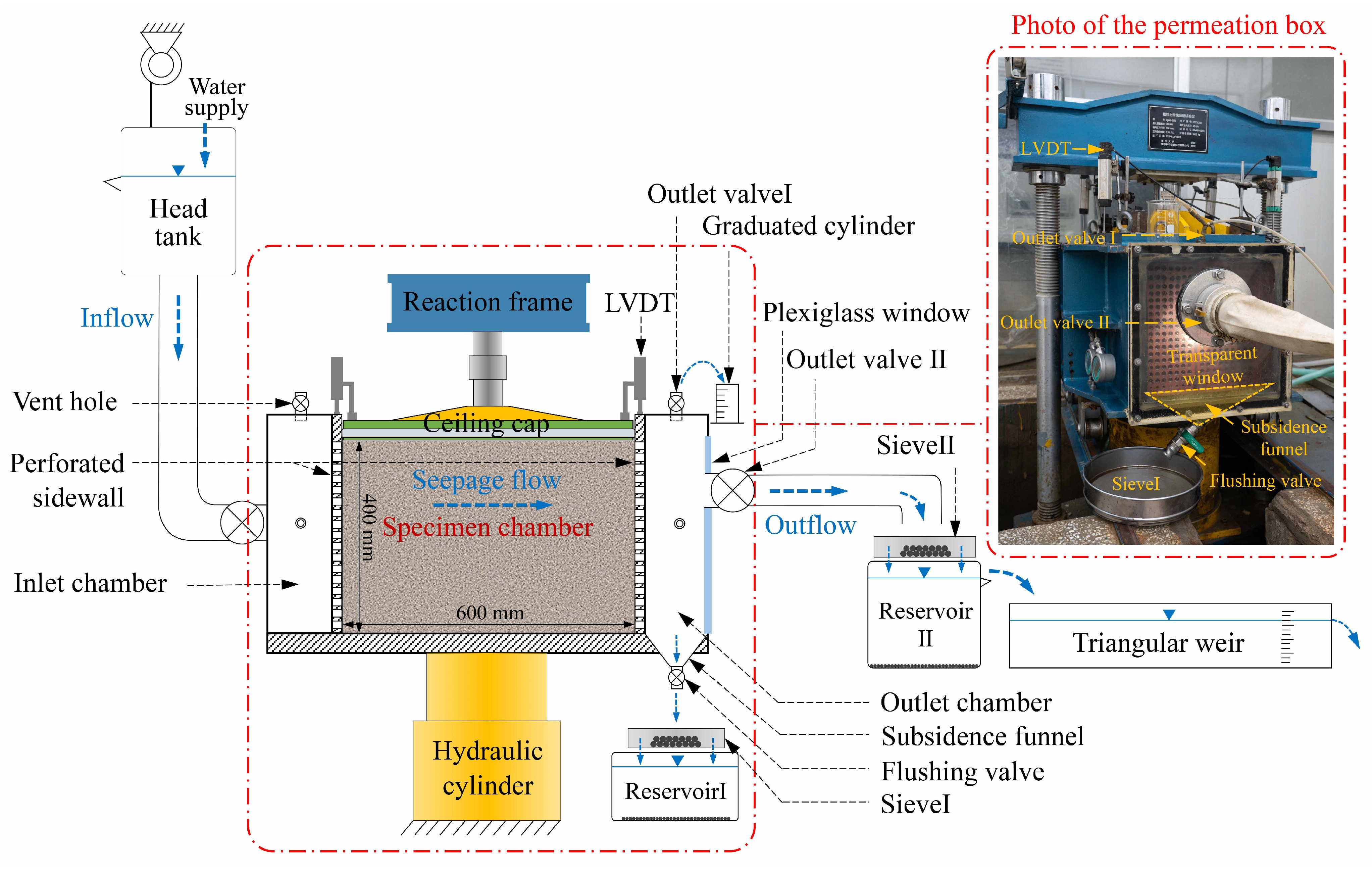
Figure 1. Schematic diagram of the large-scale high-pressure erosion apparatus.
Water 15 02660 g001
Figure 2. Photo of the test materials and the mesoscopic surface view of particles ranging from 2 to 5 mm.
Water 15 02660 g002
Figure 3. Variation of porosity with fines content in gap-graded soils (with coarse fraction ranging from 2 mm to 80 mm and fine fraction ranging from 0.075 mm to 0.5 mm) of gap ratio G r = 8, and the red-dotted line denotes the approximate critical fines content.
Water 15 02660 g003
Figure 4. Gradations of the test soils.
Water 15 02660 g004
Figure 5. Loading history of the hydraulic gradient during the internal erosion test.
Water 15 02660 g005
Figure 6. Test results of the specimens in G8P25A, G10P25A, and G8P25R: (a) variation of hydraulic conductivity with hydraulic gradient; (b) variation of fines eroded ratio with hydraulic gradient; (c) variation of volumetric strain with hydraulic gradient.
Water 15 02660 g006
Figure 7. Internal erosion characteristics of the specimens with different gap ratios: (a) variation of hydraulic conductivity with hydraulic gradient; (b) variation of fines eroded ratio with hydraulic gradient; (c) variation of volumetric strain with hydraulic gradient; (d) variation of progression hydraulic gradient with gap ratio.
Water 15 02660 g007
Figure 8. Internal erosion characteristics of the specimens with different fines contents: (a) variation of hydraulic conductivity with hydraulic gradient; (b) variation of fines eroded ratio and fines eroded mass with hydraulic gradient; (c) variation of volumetric strain with hydraulic gradient; (d) variation of progression hydraulic gradient with gap ratio.
Water 15 02660 g008
Figure 9. Mesoscopic fabric illustration to compare the change in pore channels induced by fine particle loss in: (a) soil in which fine particles under-fill the inter-granular pores; (b) soil in which fine particles precisely-fill the inter-granular pores.
Water 15 02660 g009
Figure 10. Internal erosion characteristics of the specimens with different coarse particle morphologies: (a) variation of hydraulic conductivity with hydraulic gradient; (b) variation of fines eroded ratio with hydraulic gradient; (c) variation of volumetric strain with hydraulic gradient; (d) progression hydraulic gradient and progression interstitial flow velocity in different specimens.
Water 15 02660 g010
Figure 11. Relationship of the skeleton stability index and hydraulic gradient: (a) specimens with different gap ratios; (b) specimens with different fines contents and coarse particle morphologies.
Water 15 02660 g011
Figure 12. Mesoscopic fabric illustration to compare the volumetric strain induced by fine particle loss in: (a) soil with a lower gap ratio; (b) soil with a higher gap ratio.
Water 15 02660 g012
Table 1. Morphology parameters of the coarse particle.
Particle Size Fraction
(mm)
Angular Coarse ParticlesRound Coarse Particles
SphericityRoundnessSphericityRoundness
80~400.590.690.710.89
40~200.630.780.720.89
20~100.580.840.760.96
10~50.540.890.710.97
5~20.550.920.630.96
Note: the sphericity is defined as the ratio of the minimum circumscribed circle radius of the particle to the maximum inscribed circle radius of the particle; the roundness is defined as the ratio of the equivalent ellipse circumference of the particle to the smallest circumscribed polygon circumference of the particle.
Table 2. Physical properties of the test soils.
SpecimenGap RatioFines Content (%)Coarse Particle MorphologyCuInitial Porosity
ϕ 0
G4P25A425granular63.118.7
G6.7P25A6.725granular84.218.5
G8P25A825granular87.818.1
G10P25A1025granular93.518.0
G8P10A810granular6023.6
G8P40A840granular7222.1
G8P25R825round87.816.1
Table 3. Summary of test results.
Specimen k 0 (cm/s) k f (cm/s) μ f (%) ε v , f (%) i p S s , f
G4P25A2.55 × 10−25.43 × 10−212.420.431.50.170
G6.7P25A1.69 × 10−20.1829.781.931.50.268
G8P25A2.22 × 10−20.3032.251.711.250.259
G8P25A-r1.65 × 10−20.2328.341.371.00.236
G10P25A1.83 × 10−20.9580.6010.881.00.658
G10P25A-r1.58 × 10−20.9473.0810.190.80.680
G8P10A0.630.8479.230.230.50.038
G8P40A4.63 × 10−53.64 × 10−50.080.06>3.02.391
G8P25R5.78 × 10−41.1356.88.511.250.715
G8P25R-r3.99 × 10−41.0559.99.311.250.741
Note: k 0 is the initial hydraulic conductivity, denoting the hydraulic conductivity at the beginning of the test; k f is the final hydraulic conductivity, denoting the hydraulic conductivity at the end of the test; μ f is the fines eroded ratio at the end of the test; ε v , f is the volumetric strain at the end of the test; i p is the progression hydraulic gradient; S s , f is the skeleton stability index at the end of the test.
Disclaimer/Publisher’s Note: The statements, opinions and data contained in all publications are solely those of the individual author(s) and contributor(s) and not of MDPI and/or the editor(s). MDPI and/or the editor(s) disclaim responsibility for any injury to people or property resulting from any ideas, methods, instructions or products referred to in the content.