Article

Water Erosion and Extension of Ground Fissures in Weihe Basin Based on DEM-CFD Coupled Modeling

1
School of Engineering and Technology, Institute of Geosafety, China University of Geosciences (Beijing), Beijing 100083, China
2
Key Laboratory of Earth Fissures Geological Disaster, Ministry of Natural Resources (Geological Survey of Jiangsu Province), Nanjing 210018, China
3
Engineering and Technology Innovation Center for Risk Prevention and Control of Major Project Geosafety, Ministry of Natural Resources, Beijing 100083, China
*
Author to whom correspondence should be addressed.
Water 2023, 15(13), 2321; https://doi.org/10.3390/w15132321
Submission received: 10 May 2023 / Revised: 15 June 2023 / Accepted: 19 June 2023 / Published: 21 June 2023

Abstract

:
The Weihe Basin is one of the regions with the highest concentrations of ground fissure development and the most serious disasters in China. Hidden ground fissures are formed in the shallow soil layer due to preexisting fissures generated by tectonism, hidden ground fissures suddenly exposed to the surface after heavy rainfall. Because the details of the water erosion process cannot be replicated by geological survey methods, the erosion and extension mechanism has not fully developed and the discontinuous medium numerical simulation method is well suited for simulating large deformations and facilitates a microscopic perspective in elucidating the underlying causal mechanisms. This paper deploys the discrete element method (DEM)–computational fluid dynamics (CFD) fluid–solid coupled method modeling the growth process of hidden fissures containing different soil types (sand and clay) under heavy rainfall, revealing a mechanism for the development of hidden fissures into surface fissures. The findings include: (1) the emergence process of hidden fissures into surface fissures under heavy rainfall can be summarized into four stages: subsurface erosion into hidden holes, traction into arches, collapse into sinkholes, and horizontal extension; (2) the emergence process of clay is slower than that of sand due to the constraint of cohesion; (3) the shape of the bottom seepage point affects the fissure emergence process, which is an important factor in the macroscopic performance of the exposed surface fissures. The intuitive and reproducible DEM-CFD coupled modeling used in this paper possesses important reference value for the study and prevention of water erosion ground fissures.

1. Introduction

Water is typically perceived as an adverse element in geological issues [1,2], as it frequently triggers geological disasters and engineering problems. Ground fissure is a type of geological hazard that occurs when the surface soil and rock ruptures [3,4,5]. Understanding the underlying mechanisms of the formation has been a longstanding and complex study topic. Among the various mechanisms involved, relatively less attention has been paid to fissure formation induced by water erosion. Compared with other types of ground fissures, those caused by water erosion tend to be more sudden and can result in severe damage to infrastructure and farmland [4,5].
Currently, study on water erosion ground fissures can be divided into two main categories based on the different sources of water. The first category involves ground fissures triggered by surface water seepage resulting from human activities, such as the development of ground fissures in Dali city of China, caused by improper irrigation practices over the past decade, which has led to a rise in groundwater levels and accelerated the development of ground fissures in combination with the effects of local collapsible loess [6]. The second category involves ground fissures triggered by meteorological conditions, especially heavy rainfall, which is a common cause of ground fissure disasters, such as those in the Linfen Basin of China. Many ground fissures in this area were formed in close association with heavy rainfall [7]. The mechanical properties of soil under the influence of heavy rainfall can provide favorable conditions for the development of fissures. For example, in 1996, three ground fissures emerged in the central part of the Ethiopian Rift Valley, triggered by three consecutive years of exceptionally heavy rainfall [8]. In addition, areas with hidden fissures that are subjected to heavy rainfall are highly susceptible to sudden formation of fissures. For instance, in Weihe Basin of China, Peng et al. [4] reported on the Shuanghuaishu ground fissures in Sanyuan County, where V-shaped hidden fissures caused by fault activity were exposed overnight during a heavy rainfall, forming newly emerged fissures and causing severe damage to villages. It is noteworthy that heavy rainfall appears to be a critical factor for the development of fissures in areas with hidden fissures, even those of different shapes. In the Kenyan Rift Valley, hidden fissures mostly have a rectangular shape under specific geological conditions, and the appearance of fissures is also triggered by heavy rainfall [9].
Despite substantial progress in studies on water erosion fissures, most geological survey methods are currently unable to provide a clear explanation of the emergence process. With the continuous improvement in computational methods, numerical simulations have gradually been widely applied in various engineering geological scenarios and have strong reference value [10,11].
Based on the DEM, numerical simulations can accurately track particles motion and have great natural advantages in revealing the micro-mechanics of rock-soil masses. Numerical modeling of water erosion ground fissures involves fluid-solid coupled issues. For fluids, the DEM can be coupled with various numerical fluid methods. For example, the discrete element method–direct numerical simulation (DEM-DNS) coupled method can accurately solve the flow field around particle pores to achieve precise fluid calculations. Kriebitzsc et al. [12] used this method to model the fluidization process caused by upward seepage of a granular pile composed of 2000 circular particles. However, due to the density of the fluid mesh, it is currently more commonly used in the study of two-dimensional fluid–solid problems. The discrete element method–lattice Boltzmann method (DEM-LBM) method is a discrete mesoscopic method for solving incompressible viscous flow. This method represents fluids as discrete parcels that move in fixed lattices and follow simple collision rules and can adapt to two-phase flow. Yang et al. [13] used a three-dimensional DEM-LBM to verify its accuracy by simulating benchmark cases, but due to computational constraints, this method is still limited to simulations of a small number of particles under low Reynolds numbers.
Qualitative simulation of the development process of water erosion ground fissures requires more attention to the deformation process of the rock-soil mass, rather than the precise solution of the fluid dynamics. The coupled fluid-particle system, which combines the CFD [14] with the DEM, is now popular for studying geological engineering problems involving fluid–soil interactions. Further details on the coupled method of DEM-CFD will be presented in Section 2.
The Weihe Basin is one of the regions with the highest concentration of ground fissures and is controlled by fracturing structures, which produce many intersecting hidden fissures, often in a near-V shape. Previous studies in this region have primarily relied on geological survey methods such as trenching, geological drilling, and geophysical prospection [4,5,6]. Most research findings indicate that during heavy rainfall, surface water infiltration can strongly erode along hidden fissures, leading to significant damage to farmland and buildings [4,5,15]. However, traditional geological surveys methods fall short in replicating the occurrence process of water erosion fissures. In this regard, numerical simulations can replicate its emergence process and provide a detailed investigation of its water erosion extension mechanism. In this paper, we integrate previous research findings and employ the DEM-CFD fluid-solid coupled method for modeling and simulation, and combine macroscopic phenomena with microscopic perspectives to explain the emergence process of different soil hidden fissures under heavy rainfall in this region.

2. Geological Background

The Weihe Basin is situated in the southern part of the Fenwei Basin on the Loess Plateau (Figure 1). It is also situated at the tectonic junction of the stable Ordos Block and the active North China Block, resulting in significant fault activity within the basin. Within the Weihe basin, its tributaries have cut it into unconnected blocks. The shallow surface of this region is primarily composed of loess and ancient soil layers. As a semiarid area, it is highly prone to water erosion-induced ground fissures. Field surveys have revealed that intense rainfall is a critical factor leading to the exposure of hidden fissures on the surface [4,5].
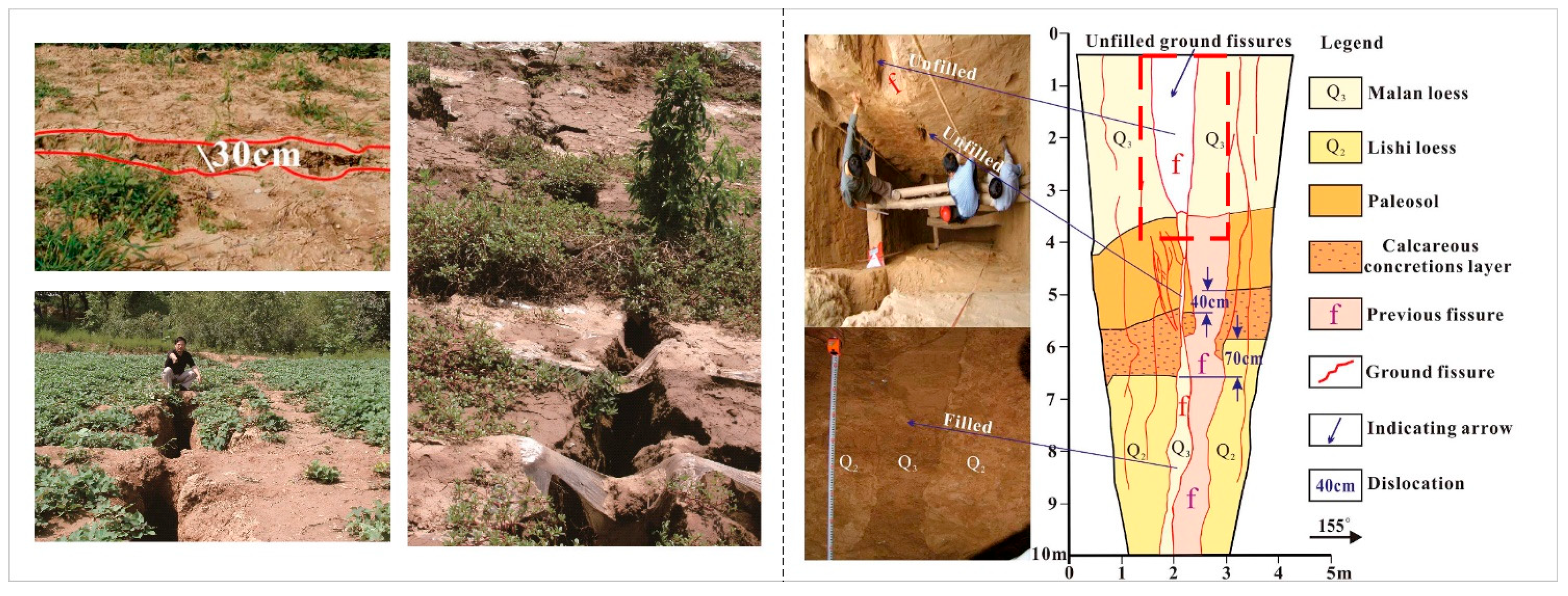
Among numerous ground fissures in the region, the Shuanghuaishu ground fissures in Sanyuan County are renowned for their sudden appearance following heavy rainfall. During a night of fissure occurrence, after enduring over two hours of heavy rainfall, two nearly parallel northeast-oriented ground fissures emerged in Shuanghuaishu village. The upper part of the hidden fissure exhibits a wider opening, gradually narrowing towards the bottom, forming a V-shaped overall structure. The red (Figure 2) section in the image represents the primary area of water erosion within the soil mass. The soil composition consists of alternating layers of loess and paleosol, with well-developed vertical joints in the loess, contributing to its good permeability [16]. On the other hand, paleosol is generally considered impermeable due to its compactness, acting as a good water barrier. Investigation reveals the presence of loess at the bottom of the fissures, indicating past surface water infiltration along the fissures, transporting upper soil layers and depositing them at the base. This process serves as the primary cause for the sudden exposure of hidden fissure on the ground surface.
Furthermore, the region experiences a significant increase in ground fissure activity following the rainy season, often characterized by beadlike sinkholes or collapse holes. Field investigations have revealed that during the period from 2000 to 2007, there was a higher frequency of ground fissure activity, which coincided with the trend in annual precipitation observed by the meteorological bureau (Figure 3). The opening of water erosion-induced ground fissures in this area is closely related to rainfall.

3. DEM-CFD Coupled Numerical Modeling Method

This paper employs the DEM-CFD coupled numerical modeling method to examine the emergence process of V-shaped hidden fissures during heavy rainfall in the Weihe Basin. The behavior of solid particles is modeled using the three-dimensional Particle Flow Code (PFC3D V5.0) software, while fluid behavior is solved by a modified Python script that utilizes the open-source Fipy library to solve the Darcy equation. The simulation technique is implemented by integrating the particle dynamics and fluid dynamics [17].

3.1. Background: The Coupling of DEM and CFD

The DEM-CFD coupled method for numerical simulations is based on the Euler–Lagrange framework, where the particle motion and collision are calculated using the DEM. The CFD solver typically uses the finite volume method (FVM) for solving, and the Tsuji coarse-mesh fluid-particle numerical analysis system is used for coupling [18]. This method discretizes the continuous fluid into elements for solution, which does not finely solve the flow field around particles. Darcy’s law is commonly used to describe fluid movement in porous media for seepage problems.
As the most commonly used method for fluid–solid coupling, DEM-CFD has been widely applied in fields such as soil mechanics and geology. Zhao et al. [10] utilized the DEM-CFD method to solve two classic geological problems and obtained verification, indicating its good robustness, and subsequently applied it to rock and mining engineering problems. Guo et al. [19] established a coupled model using the DEM-CFD method to investigate the influence of different sand particle shapes on internal erosion of sand. Wang et al. [20] explored the factors affecting the seepage of two types of particles, and summarized through a large number of simulations that the final erosion rate is affected by the content of fine particles and porosity ratio, and proposed a predictive model for the final erosion rate through dimensional analysis.

3.2. Details of the DEM-CFD Coupled Modeling Method

3.2.1. Governing Equations of the Particle Phase

In the DEM, solids are represented by particles, and the motion of particles follows Newton’s laws of motion in the Lagrangian framework, which are controlled by the governing equations. The control equations for particles in the PFC3D software are as follows:
u t = f m e s h + f f l u i d m p + g
ω t = M p I p
where u is the particle translational velocity; t is the time; f m e c h is the total force acting on the particles; f f l u i d is the total of the fluid–particle interaction forces applied on the particle by the fluid; m p is the mass of the particle; g is the gravitational acceleration; ω is the angular velocity of the particle; M p is the moment of contact force acting on the particle; and I p is the moment of inertia of the particle [21].

3.2.2. Darcy’s Law

The CFD module in PFC3D was utilized to model three-dimensional flow through porous media. In this paper, the behavior of fluid infiltrating the soil under rainfall is described using Darcy’s law and continuity equation, as follows:
v = K μ ε p
v = 0
where v is the average fluid velocity; p is the average pressure in a fluid element; ε is the porosity; μ is the fluid dynamic viscosity, and K is the matrix permeability, the value of which is computed based on the ε and the Kozeny–Carman relationship [22], as follows:
K = 1 180 ε 3 ( 1 ε ) 2 d 2
where d is the average diameter of particles. By combining Equations (3) and (4), the Poisson equation can be derived:
( K μ ε p ) = 0

3.2.3. Coupling Process

In the modeling process, particular attention is paid to the coupling process between fluid and solid, wherein fluid–solid interaction forces, including drag force ( f d ) and pressure gradient force ( f p ), as follows:
f f l u i d = f d + f p
The gradient force acting on particles is expressed as:
f p = v p p
where v p is the volume of particles. The drag force acting on particles is predominantly attributed to the velocity differential between fluid elements and particles, and can be represented using the Di Felice theory [23]:
f d = 1 2 C d ρ f π r p 2 | v u | ( v u ) ε χ
C d = ( 0.63 + 4.8 Re p )
Re p = 2 ρ f r p | v u | μ
χ = 3.7 0.65 exp ( ( 1.5 lg Re p ) 2 2 )
where C d is the drag coefficient; r p is the radius of the particles; ρ f is the fluid density; Re p is the particle Reynolds number, and ε χ is an empirical term, which is used to account for the local porosity.
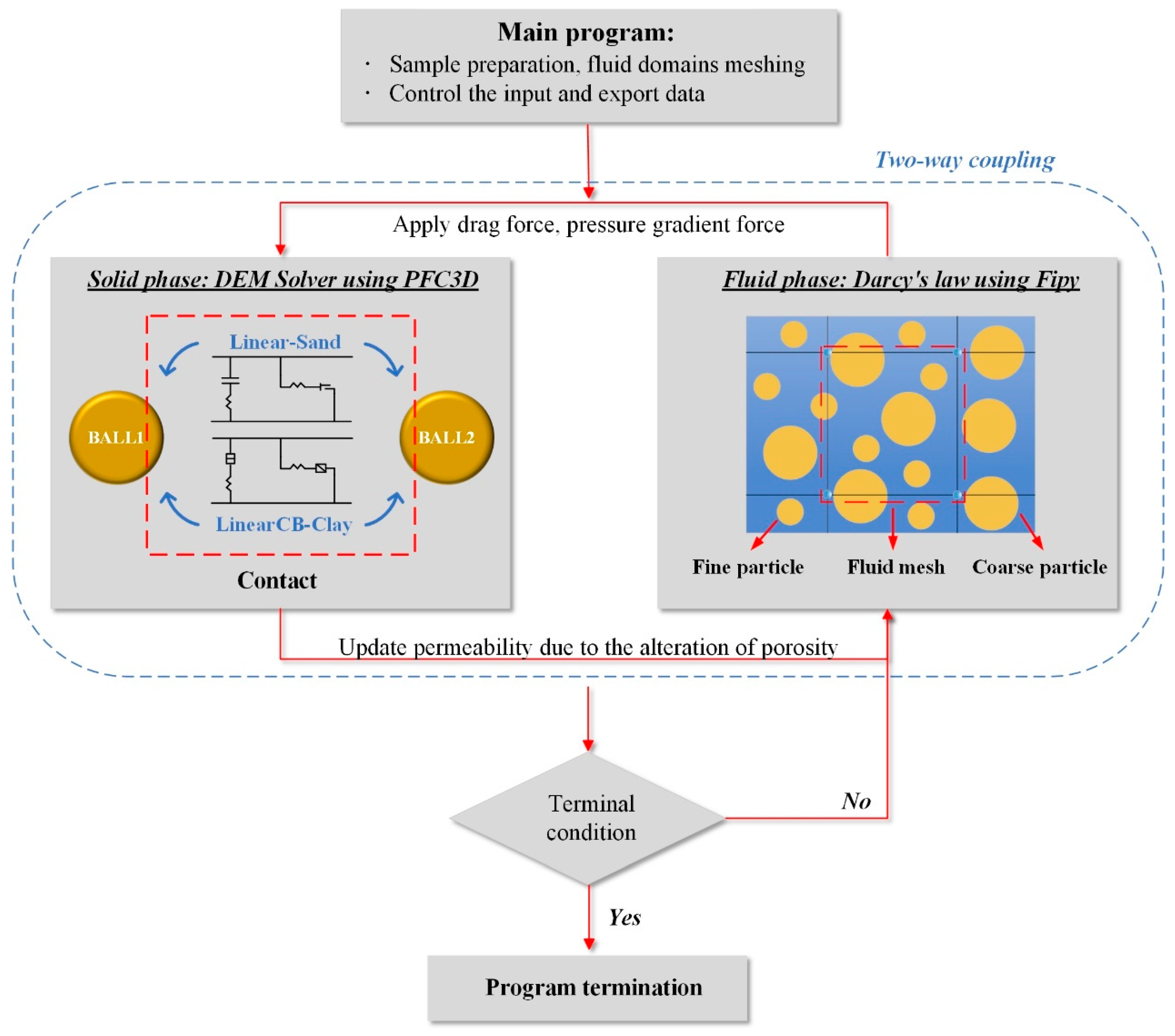
Figure 4 illustrates the two-way coupling procedure between PFC3D and Python. After particle assembly in PFC3D, the CFD module is used for coupling. During the coupling process, the CFD solver employs the Fipy library in Python to divide the mesh and solve the equations of fluid motion using the finite volume method. The two software packages exchange information explicitly. PFC3D updates particle motion using Newton’s second law and sends the calculated pore and fluid forces to the CFD module for further analysis. The CFD solver, which utilizes the Fipy library in Python, applies the finite volume method to solve the governing equations of fluid motion on the meshed domain. Both programs explicitly exchange information in PFC3D, and the calculated fluid velocity and pressure are sent back to PFC3D for iterative updating of the particle positions and velocities until equilibrium is reached.

3.3. Building of the Computational Model

Figure 5 illustrates the relationship between the actual problem and the numerical model approach. The objective is to investigate the opening process of hidden fissures in different soil fillings under the influence of heavy rainfall. The CFD mesh is created to analyze the flow field, with the fluid mesh raised by one element to model vertical rainfall infiltration. The filling soil in the fissures is modeled using the DEM. In order to investigate the effect of different soils, the linear contact model and linear contact bond model were adopted to represent the sand and clay, respectively, based on whether there is cohesive force between particles. The linear model is suitable for situations where there is no cohesive force between particles, such as sand, where each particle is represented by a spring in the normal and tangential directions of forces that can only withstand pressure. The linear contact bond model is based on the linear model, but assigns a certain tensile and shear capacity to the spring, allowing for better simulation of the mechanical properties of materials, such as cohesive soil. When the bond is broken, it reverts back to the linear model. By comparing the simulation results, we summarize the mechanism of hidden fissures development in different soils under heavy rainfall.

3.4. Determination of Computational Parameters

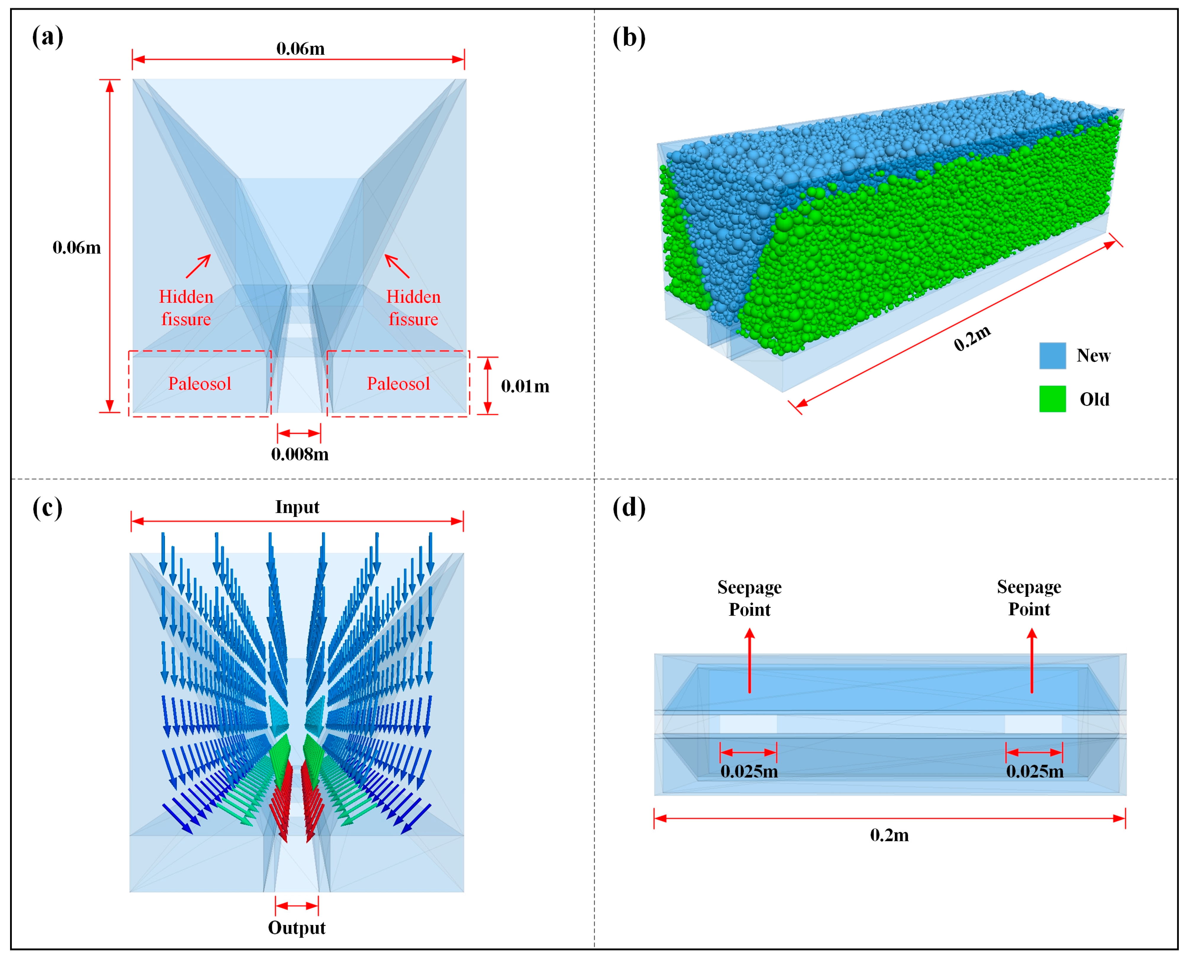
Figure 6 depicts the model configuration. Due to computational constraints, the soil material inside the hidden fissures is modeled as a mixture of coarse and fine particles to induce percolation failure, with a maximum coarse particle diameter of 0.005 m and a minimum fine particle diameter of 0.001 m. The model configuration is based on examples of ground fissures in the Weihe Basin [4,5], with the hidden fissure set as a V-shape, the width and height of the model both set to 0.06 m, while the length is 0.2 m. With the fissure top of 0.05 m and the seepage fissure width of 0.008 m at the bottom, hidden fissures are represented through the wall elements and given consistent contact and mechanical parameters with the surrounding soil. The model generated a total of 47,702 particles, with coarse particles accounting for 20% of the total, which satisfies the requirement of having a representative volume element (RVE) with a coarse particle count greater than 500 [24,25]. For fluid, the mesh generation of fluid domain plays a crucial role in capturing the fluid flow. As indicated by previous studies [22,26,27,28], the mesh size should be greater than 1–4 times the average particle diameter, and at least 5 fluid elements should exist in each direction. In our model, due to the influence of bottom seepage width on the failure process, an odd number of fluid elements in the seepage width will lead to uneven stress on the soil inside the fissure, thus requiring an even number of fluid elements in each direction. Therefore, we divided the fluid domain into 6 elements in the x and z directions, with a length of 0.01 m per element, and into 20 elements in the y direction, with a length of 0.01 m per element. The coupling interval was set to 100. Combining practical issues with existing studies [29,30,31], the specific simulation parameters are given in Table 1.
To better model the loose state of the soil inside the fissure, many particles were formed above the fissure and allowed to settle into it under gravity. The excess particles above the surface were then removed to create a representative sample. As the underlying paleosol was treated as a good water barrier, its thickness was set to 0.01 m. The fluid outlet was located at the position of the bottom fissure and two seepage points were established. The critical hydraulic gradient state of model was determined through extensive simulations to induce water erosion.

4. Results and Analysis

Under the impact of heavy rainfall, the soil particles gradually migrate, resulting in soil seepage failure. The preexisting hidden fissures in the soil become the dominant channel for surface water seepage, greatly affecting the macroscopic opening process of ground fissures. This section investigates the water erosion extension process of different soils.

4.1. Subsurface Erosion into Hidden Holes

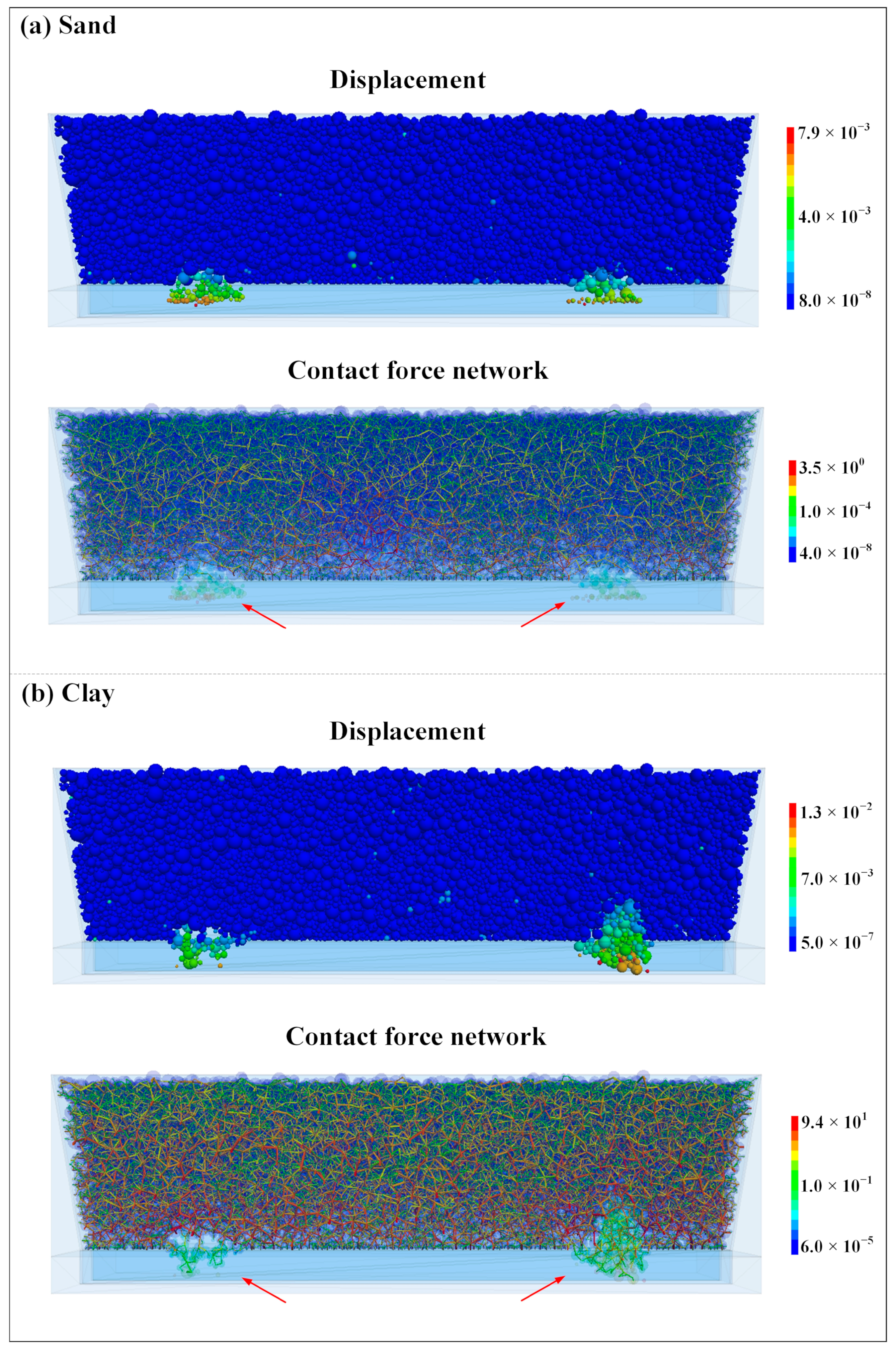
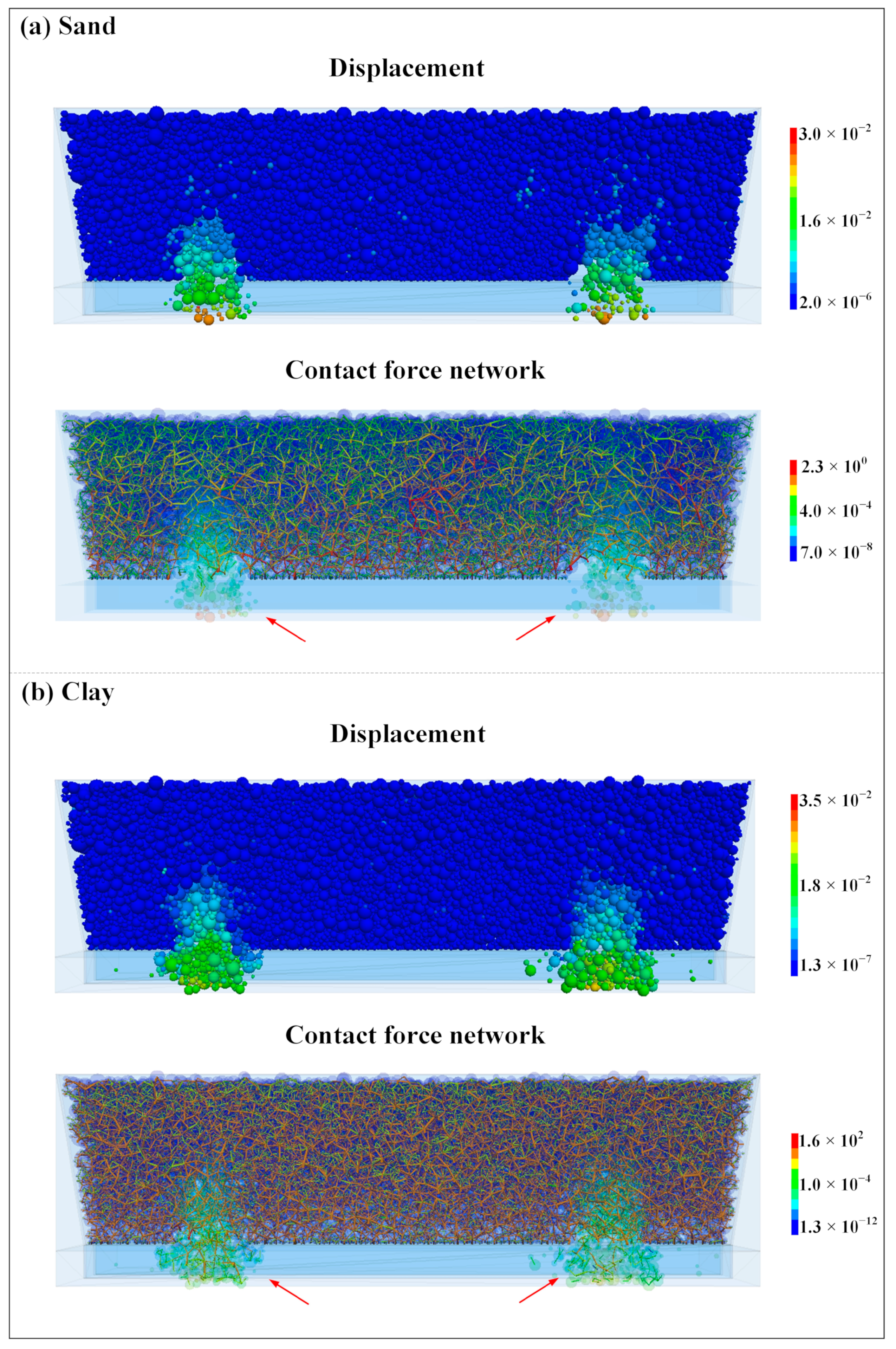
Figure 7 shows the displacement process and contact network that occur in the initial stage for sand and clay. The displacement distribution indicates that fine particles in sand and a few coarse particles begin to drop locally near the seepage point, while the contact network shows the disappearance of contact between the dropped particles and the body, indicating the occurrence of incipient erosion at the bottom and the formation of small hidden holes (Figure 7a). In clay, the coarse and fine particles cluster into small blocks and drop locally near the seepage point, forming small hidden holes, and the contact network shows the disappearance of contact between the dropped block and the body, but contact forces still exist between the particles within the block (Figure 7b). Unlike sand particles, which fall off individually, the presence of cohesive forces in clay increases the interparticle connectivity, leading to the blocky detachment of particles as the main cause. The contact network also reveals that the interaction forces between clay particles are much greater than those between sand particles. Figure 8 displays the development of the hidden hole after a modeled period of time. In comparison to Figure 7, the hidden holes have obviously expanded and show a tendency to develop upward. In sand, particle detachment remains mostly single particles, whereas in clay, the detached chunks become larger. Due to the formation of hidden holes, interparticle forces increase, stabilizing the main body.

4.2. Traction into Arches

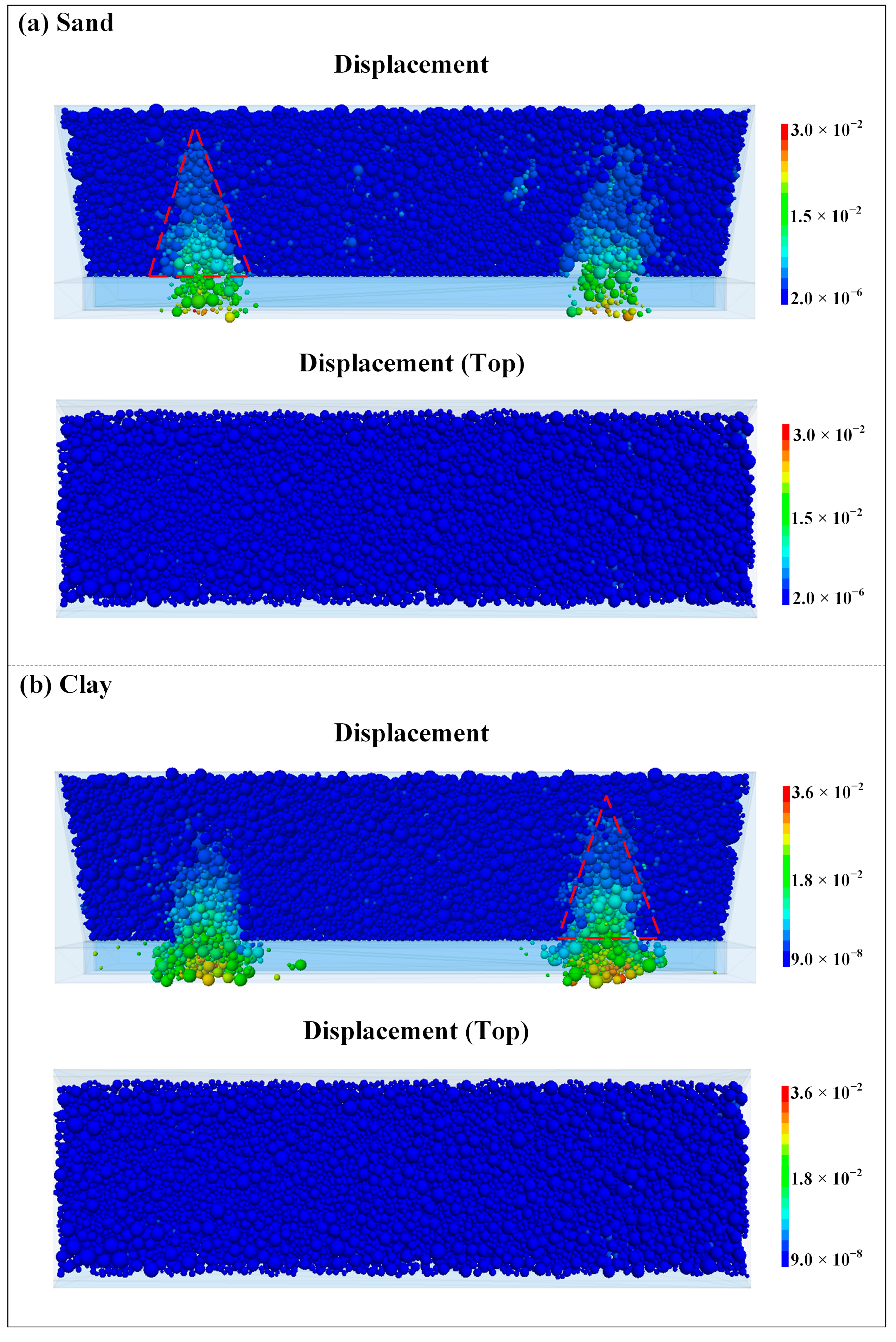
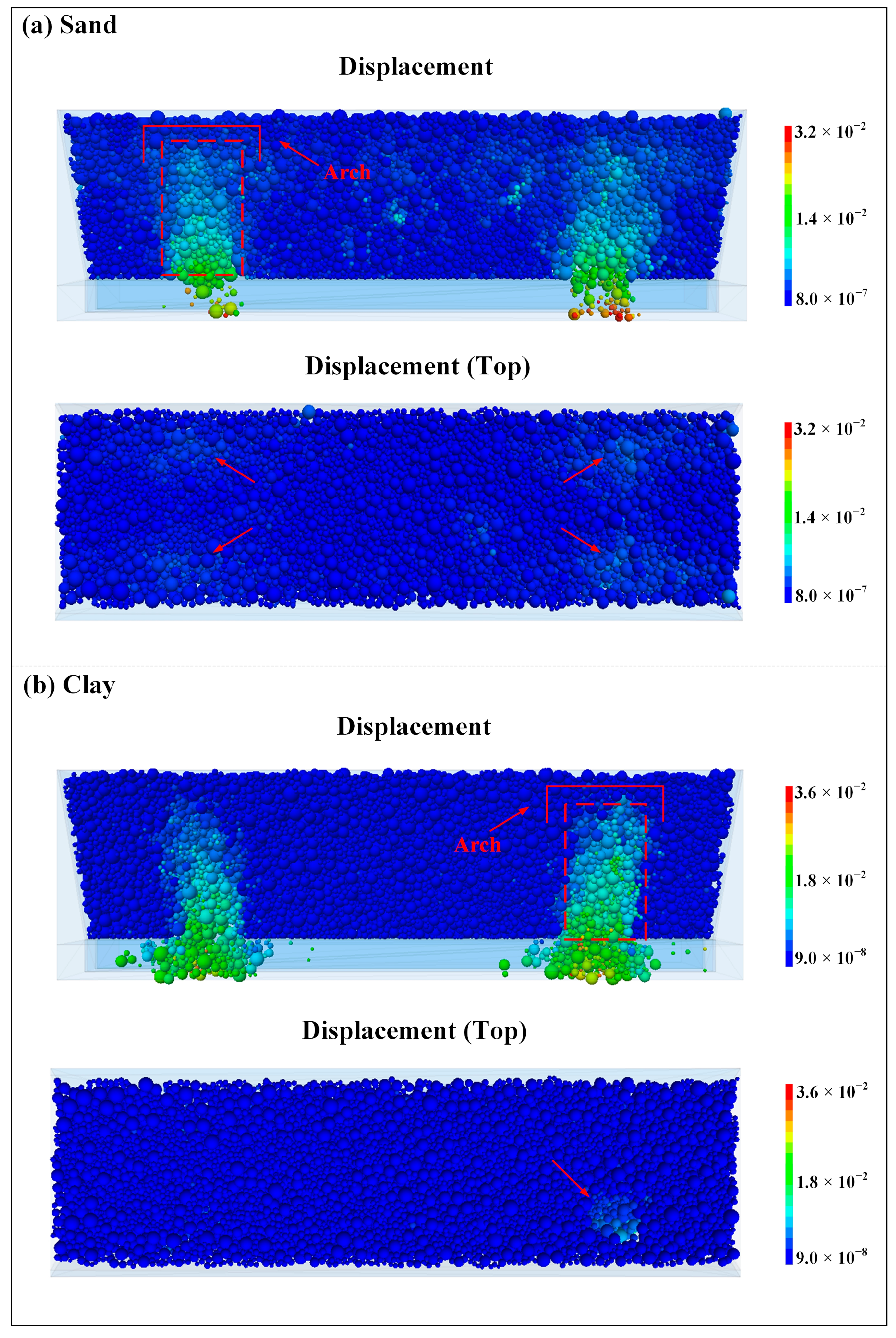
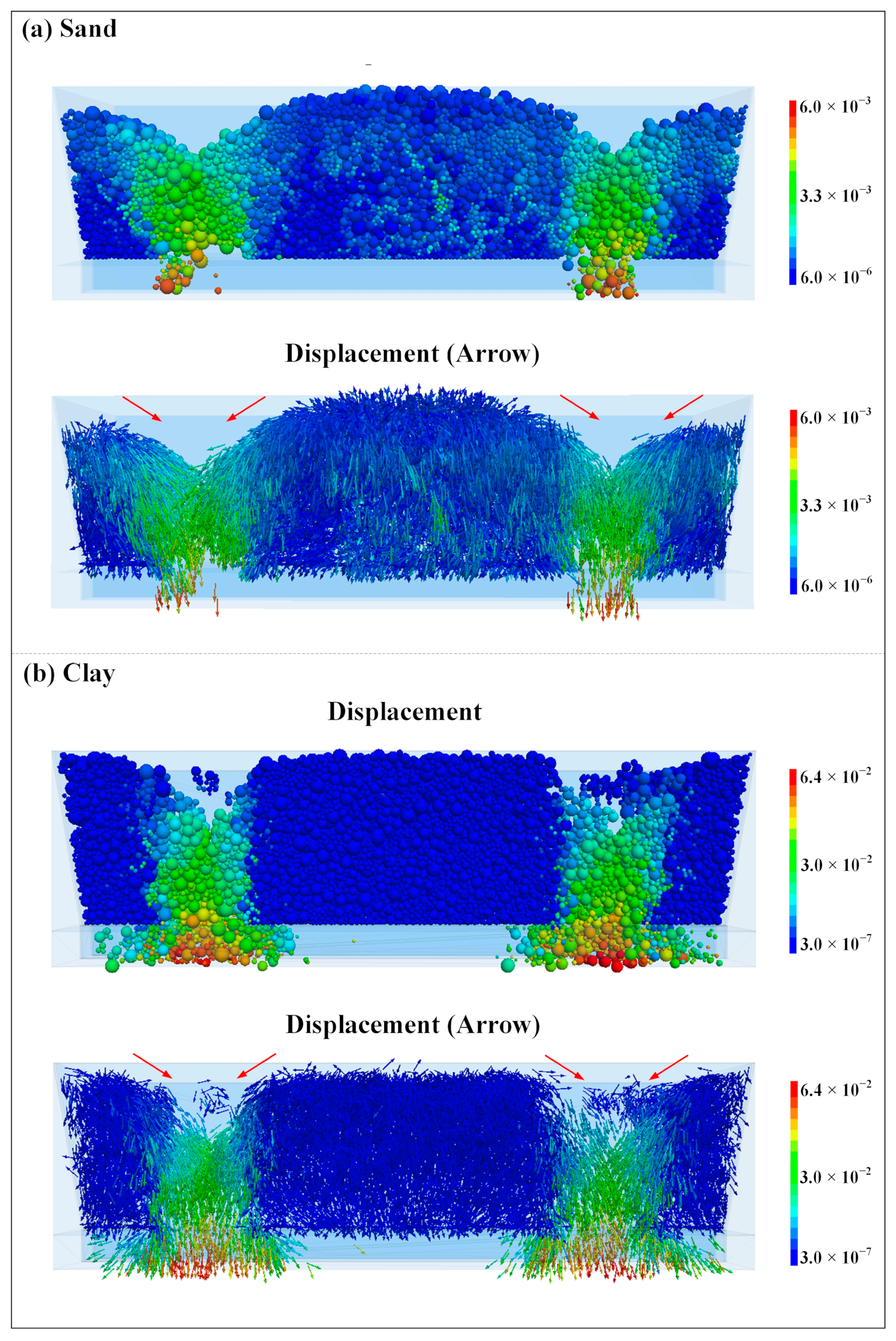
Figure 9 illustrates the upward development of the hidden holes. It is worth noting that regardless of whether it is sand or clay, when the voids reach a certain height, the soil mass above the voids undergoes collective displacement in a very short time, forming a triangle shape with a pointed top and a broad base. However, the voids do not extend to the ground surface. Figure 10 illustrates the surface displacement of both sandy and clayey soils. It can be observed that the distribution of displacement has changed from a triangular shape to an approximately rectangular shape. This is likely due to the fact that the grains on both sides of the triangle fall under the combined traction of gravity and seepage, leading to the release of stress in the soil, which supports the stability of the overlying soil. However, when the distribution of displacement expands from the triangle to the rectangle, the decrease in stress cannot support the overlying soil against the erosive effect of water flow, causing the overlying soil to loosen and the surface to start moving suddenly.

4.3. Collapse into Sinkholes

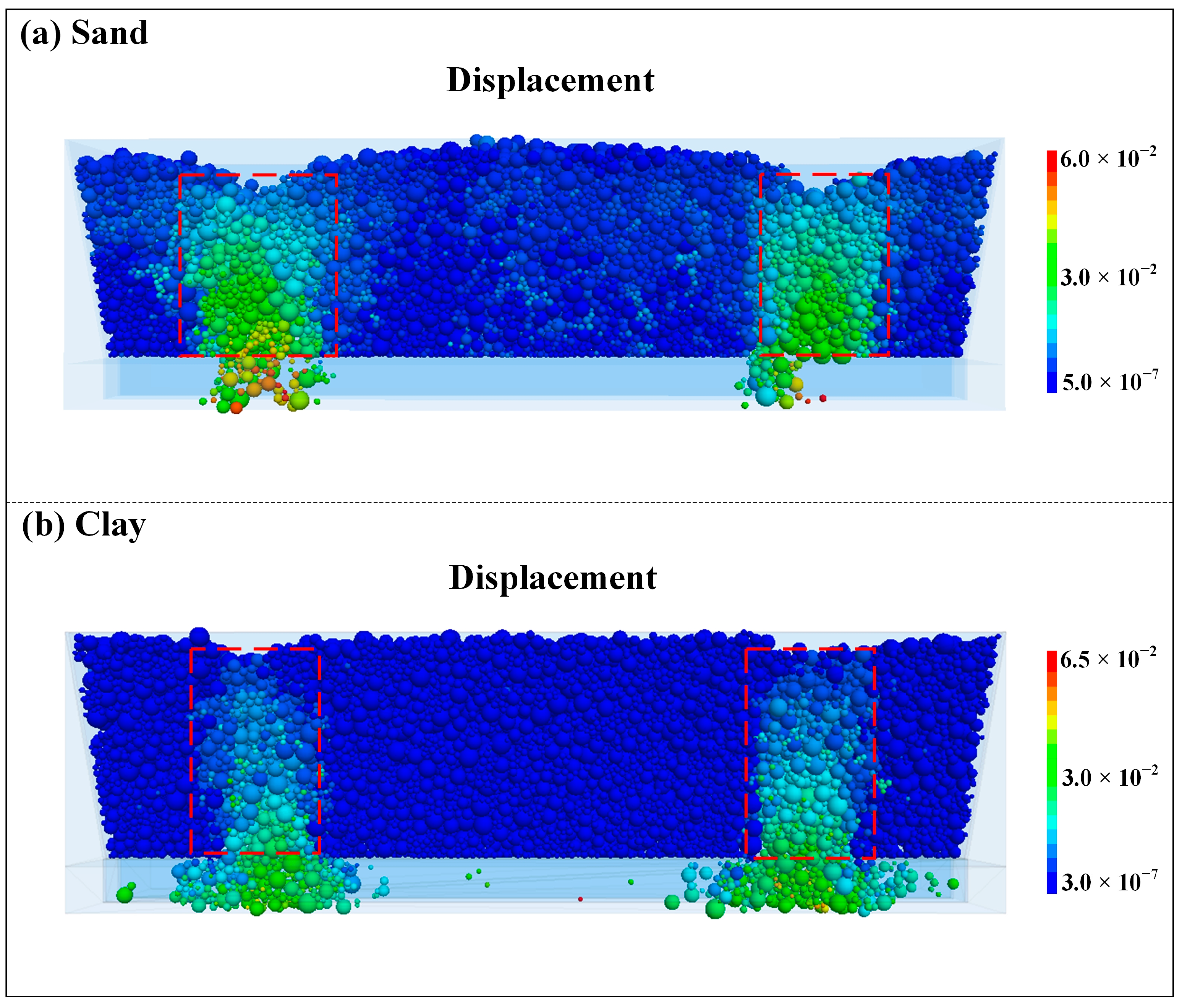
After surface displacement occurs, the overlying soil particles begin to collapse collectively. Figure 11 shows the collapsing process of sand and clay. At the initial stage of collapse, the soil particles in the collapse zone move at a higher velocity than those on the sides, resulting in a slower inward movement of the soil on both sides of the collapse zone. This results in the overall displacement distribution taking on a rectangular shape and gradually moving downwards, forming a collapse sinkhole during this stage.

4.4. Horizontal Extensions

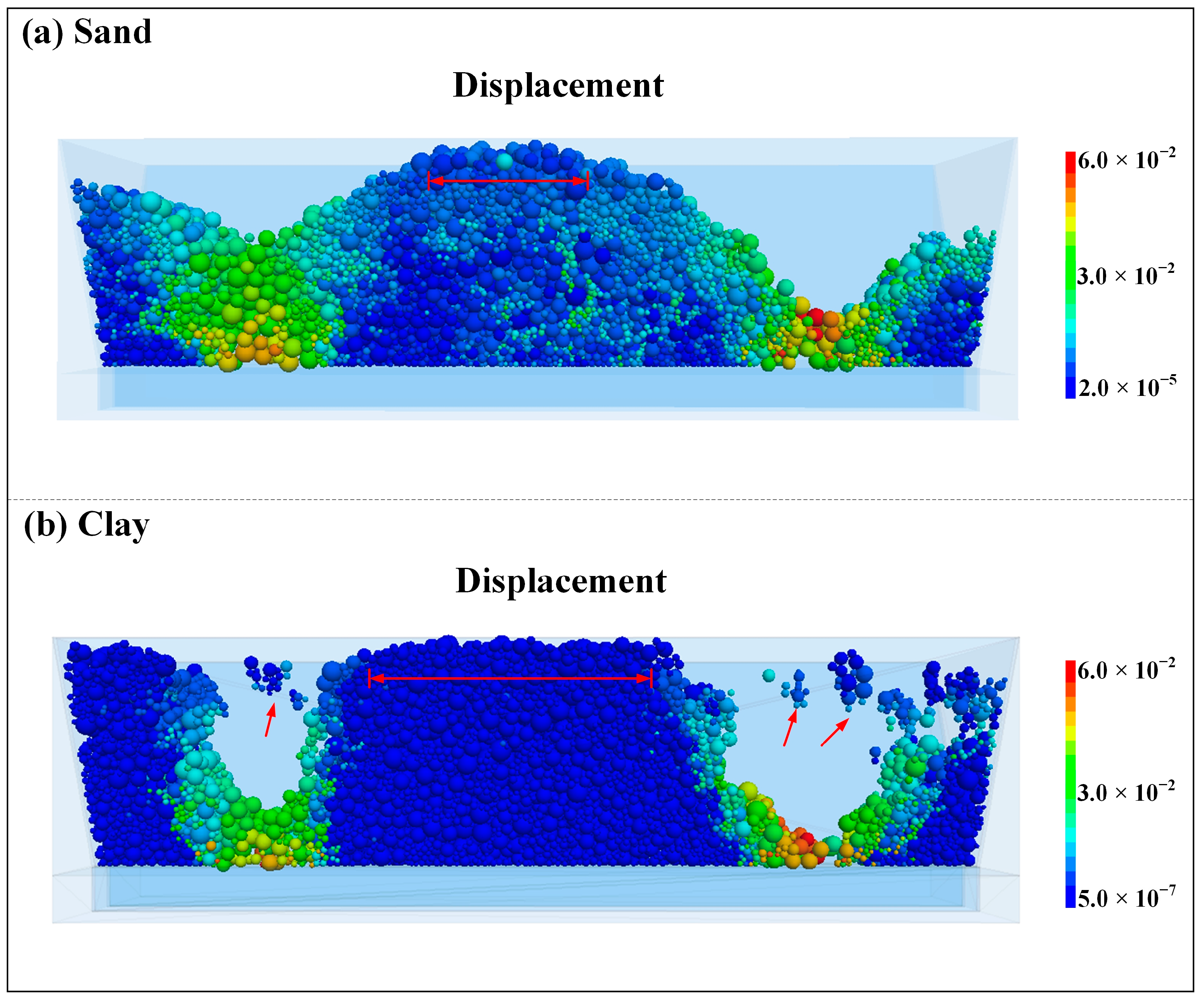
Figure 12 shows the displacement direction of the particles. As the depth of the collapsed hole increases, the soil on both sides of the hole will collapse inward, causing the collapsed hole to expand horizontally. Figure 13 shows the longitudinal development of a collapsed hole on one side to the bottom. Regardless of whether it is sand or clay, the final distribution is similar to a W-shape. The length of the bottom of the depression is basically the same as that of the seepage point, indicating that the shape of the seepage point at the bottom has a significant impact on the macroscopic manifestation of the exposed surface of the hidden fissure. In addition, during the process of particle collapse, a large number of soil particles move downward and accumulate at the bottom, and may reform an effective structure to resist fluid erosion. Comparison of Figure 13a,b reveals that the central portion of the sand gradually collapses with the formation of two horizontal sinkholes, while the majority of the soil in the center of the clay remains stable, with a few particles adhering to the fissures. This is because the clay has tensile strength that makes its horizontal extension significantly slower than that of the sand, which can be obviously observed as an increase in the distance between the two sinkholes at the surface.
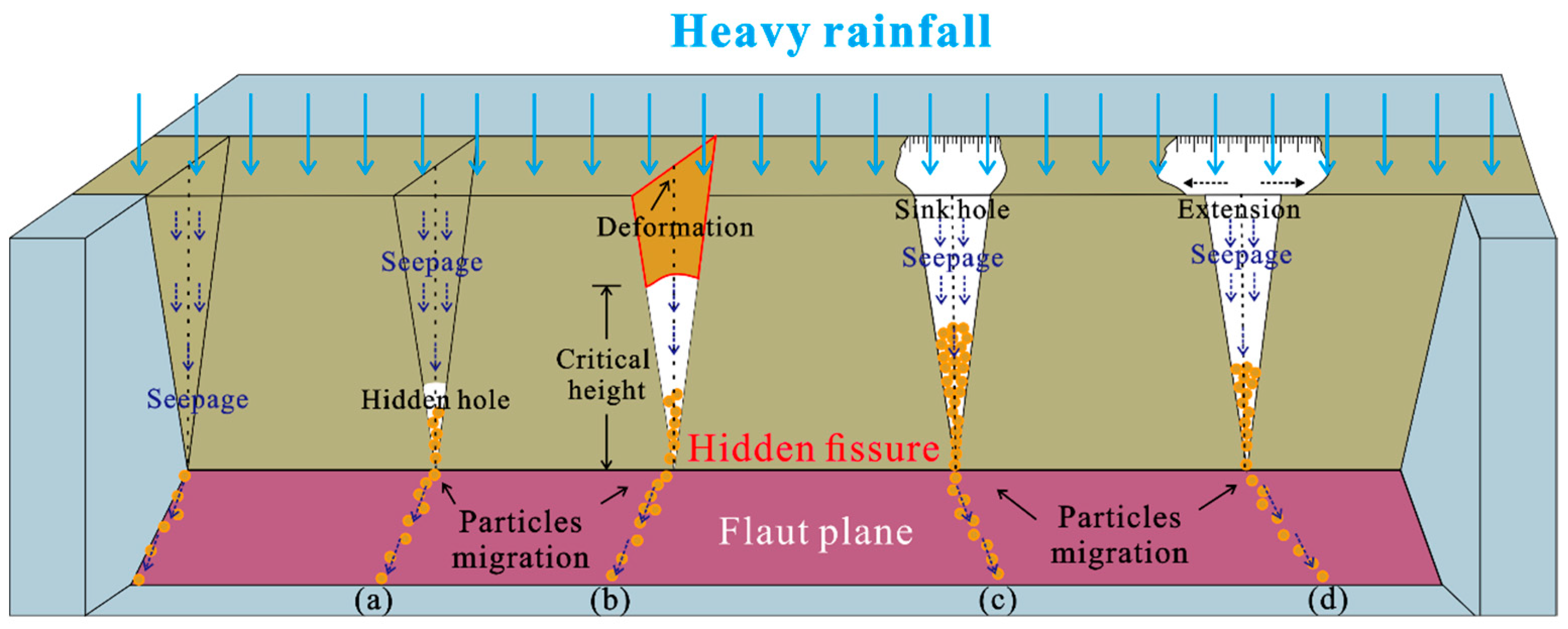
Figure 14 illustrates the complete process of reopening hidden fissures. In general, the emergence process can be divided into four stages following rainfall seepage: subsurface erosion into hidden holes, traction into arches, collapse into sinkholes, and horizontal extension, corresponding to stages (a–d) of Figure 14, respectively.

5. Discussion

This paper explored the relatively understudied phenomenon of water erosion-induced ground fissures, and revealed the growth and development mechanisms of hidden fissures in the Weihe Basin under heavy rainfall using the DEM-CFD numerical simulation method from a microscopic perspective. The findings provide important references for the study and prevention of water erosion ground fissures.
To the authors’ knowledge, most studies on water erosion fissures have relied on geological surveys to infer the development process [4,5]. Overall, the inferred results are consistent with the three stages of subsurface erosion into hidden holes, collapse into sinkholes, and horizontal extension presented in this paper. Compared to traditional methods, numerical simulation can present more details and reveal causal mechanisms from a micro perspective, especially in the stage of traction into arches, where the changes in arch shape are difficult to discern with geological survey methods.
This paper has some disadvantages that should be noted. One important issue is the model size. Due to the high computational requirements of the discrete element method, it is difficult to simulate real-scale models, which is often considered a major drawback of the discrete element method. Additionally, in order to save computational resources, we assumed that soil particles were circular, whereas in reality they are often irregular in shape. To better model the development of water erosion ground fissures, future work will consider using a coupled finite difference method (FDM) and discrete element method (DEM) to establish models that are closer to the hillslope scale, and will use irregular shapes to model soil particles, which can more realistically reflect particle migration and increase the reliability of simulation results. Beyond the constraints in simulation methods, factors such as the rainfall intensity, shape of hidden fissures and terrain conditions all exert direct or indirect effects on the process of fissures growth. It is crucial to delve deeper into the analysis of diverse factors that influence fissure development.

6. Conclusions

This paper employs the DEM-CFD coupled method to investigate the emergence process of hidden ground fissures in the Weihe Basin, building upon existing geological surveys. By simulating different soil types, it unveils a mechanism that hidden fissures develop into fissures under conditions of intense rainfall. These findings are comparable with prior research in this region, and the results provide further insights into the erosive effects of rainwater on soil particles.
The research results indicate that preexisting hidden fissures become the dominant channel for surface water seepage, leading to the formation of hidden holes at a certain depth due to the occurrence of seepage erosion at the bottom. As seepage erosion continues, the upper part of the hidden hole collapses and extends horizontally, eventually developing into ground fissures. The overall process can be divided into four stages: subsurface erosion into hidden holes, traction into arches, collapse into sinkholes, and horizontal extension. Compared to clay, sand is more prone to lateral extension due to the absence of cohesive forces between particles. Furthermore, the shape of leakage points at the bottom is an important factor in the macroscopic manifestation of exposed hidden fissures into the ground.
This study demonstrates the feasibility of the DEM-CFD coupled method in the investigation of water erosion ground fissures. The method can be applied for modeling and simulation purposes under various regional and geological conditions. The findings hold significant scientific implications for the research and prevention of water erosion ground fissures.

Author Contributions

Conceptualization, F.W. (Fujiang Wang) and F.W. (Feiyong Wang); methodology, F.W. (Fujiang Wang); software, F.W. (Fujiang Wang); formal analysis, F.W. (Fujiang Wang); investigation, F.W. (Fujiang Wang), G.L. and F.W. (Feiyong Wang); resources, F.W. (Fujiang Wang), X.G.; data curation, F.W. (Fujiang Wang); writing—original draft preparation, F.W. (Fujiang Wang); writing—review and editing, F.W. (Feiyong Wang), Y.Z. and X.G.; visualization, F.W. (Fujiang Wang); project administration, F.W. (Feiyong Wang); funding acquisition, F.W. (Feiyong Wang). All authors have read and agreed to the published version of the manuscript.

Funding

This research was funded by the National Science Foundation of China (42293351, 42207202, 2022XAGG0400), the CRSRI Open Research Program (Program SN: CKWV2021873/KY), the Fundamental Research Funds for the Central Universities (2-9-2021-014), the Key Laboratory Open Fund (EFGD2021-05-02, 300102262509).

Data Availability Statement

Data is contained within the article.

Conflicts of Interest

The authors declare no conflict of interest.

References

  1. Zheng, X.; Xu, J.; Wang, H.; Liu, X.; Yao, D.; Lv, J. Health risk assessment of a reservoir-type water source in the northeastern region of China. Hum. Ecol. Risk Assess. Int. J. 2017, 23, 751–766. [Google Scholar] [CrossRef]
  2. Lu, Y.; Xu, J.; Wang, H.; Liu, X.; Li, W. Distribution, sources and health risk assessment of contaminations in water of urban park: A case study in Northeast China. Environ. Geochem. Health 2019, 41, 2473–2489. [Google Scholar] [CrossRef]
  3. Burbey, T.J. The influence of faults in basin-fill deposits on land subsidence, Las Vegas Valley, Nevada, USA. Hydrogeol. J. 2002, 10, 525–538. [Google Scholar] [CrossRef]
  4. Peng, J.B.; Wang, F.Y.; Cheng, Y.X.; Lu, Q.Z. Characteristics and mechanism of Sanyuan ground fissures in the Weihe Basin, China. Eng. Geol. 2018, 247, 48–57. [Google Scholar] [CrossRef]
  5. Wang, F.Y.; Peng, J.B.; Lu, Q.Z.; Cheng, Y.X.; Meng, Z.J.; Qiao, J.W. Mechanism of Fuping ground fissure in the Weihe Basin of northwest China: Fault and rainfall. Environ. Earth Sci. 2019, 78, 10. [Google Scholar] [CrossRef]
  6. Zang, M.D.; Peng, J.B.; Qi, S.W. Earth fissures developed within collapsible loess area caused by groundwater uplift in Weihe watershed, northwestern China. J. Asian Earth Sci. 2019, 173, 364–373. [Google Scholar] [CrossRef]
  7. Li, Y.L.; Yang, J.C.; Hu, X.M. Origin of ground fissures in the Shanxi Graben system, Northern China. Eng. Geol. 2000, 55, 267–275. [Google Scholar] [CrossRef]
  8. Ayalew, L.; Yamagishi, H.; Reik, G. Ground cracks in Ethiopian rift valley: Facts and uncertainties. Eng. Geol. 2004, 75, 309–324. [Google Scholar] [CrossRef]
  9. Liu, Y.; Peng, J.B.; Jiang, F.Q.; Lu, Q.Z.; Zhu, F.J.; Qiang, X. Model test study on the formation and development of underground erosion ground fissures in the Kenya Rift Valley. J. Mt. Sci. 2022, 19, 1037–1050. [Google Scholar] [CrossRef]
  10. Zhao, J.D.; Shan, T. Coupled CFD-DEM simulation of fluid-particle interaction in geomechanics. Powder Technol. 2013, 239, 248–258. [Google Scholar] [CrossRef]
  11. Wang, Y.; Xia, A.; Qin, G. Probabilistic modeling for reliability analysis of buried pipelines subjected to spatiotemporal earthquakes. Probabilistic Eng. Mech. 2022, 69, 103315. [Google Scholar] [CrossRef]
  12. Kriebitzsch, S.H.L.; van der Hoef, M.A.; Kuipers, J.A.M. Fully resolved simulation of a gas-fluidized bed: A critical test of DEM models. Chem. Eng. Sci. 2013, 91, 1–4. [Google Scholar] [CrossRef]
  13. Yang, G.C.; Jing, L.; Kwok, C.Y.; Sobral, Y.D. A comprehensive parametric study of LBM-DEM for immersed granular flows. Comput. Geotech. 2019, 114, 15. [Google Scholar] [CrossRef] [Green Version]
  14. Ferziger, J.H.; Peric, M. Computational Methods for Fluid Dynamics; Springer: Berlin, Germany, 1999. [Google Scholar]
  15. Meng, Z.J.; Wang, F.Y.; Peng, J.B.; Qiao, J.W.; Wen, H.G. Characteristics and mechanism of Jiaocheng ground fissure in Taiyuan Basin, China. Environ. Earth Sci. 2023, 82, 10. [Google Scholar] [CrossRef]
  16. Sun, P.; Peng, J.B.; Chen, L.W.; Yin, Y.P.; Wu, S.R. Weak tensile characteristics of loess in China—An important reason for ground fissures. Eng. Geol. 2009, 108, 153–159. [Google Scholar] [CrossRef]
  17. Guyer, J.E.; Wheeler, D.; Warren, J.A. FiPy: Partial Differential Equations with Python. Comput. Sci. Eng. 2009, 11, 6–15. [Google Scholar] [CrossRef]
  18. Tsuji, Y.; Kawaguchi, T.; Tanaka, T. Discrete particle simulation of two-dimensional fluidized bed. Powder Technol. 1993, 77, 79–87. [Google Scholar] [CrossRef]
  19. Guo, Y.; Yang, Y.; Yu, X. Influence of particle shape on the erodibility of non-cohesive soil: Insights from coupled CFD-DEM simulations. Particuology 2018, 39, 12–24. [Google Scholar] [CrossRef]
  20. Wang, X.K.; Huang, B.; Tang, Y.; Hu, T.T.; Ling, D.S. Microscopic mechanism and analytical modeling of seepage-induced erosion in bimodal soils. Comput. Geotech. 2022, 141, 15. [Google Scholar] [CrossRef]
  21. Itasca Consulting Group, Inc. PFC 5.0 Documentation, User’s Guide; 2018. Available online: https://www.itascacg.com/software/pfc (accessed on 14 June 2023).
  22. Itasca Consulting Group, Inc. PFC—Particle Flow Code, Ver. 5.0; 2014. Available online: https://www.itascacg.com/software/pfc (accessed on 14 June 2023).
  23. Difelice, R. The Voidage Function for Fluid Particle Interaction Systems. Int. J. Multiph. Flow 1994, 20, 153–159. [Google Scholar] [CrossRef]
  24. Shire, T.; O’Sullivan, C.; Hanley, K.J.; Fannin, R.J. Fabric and effective stress distribution in internally unstable soils. J. Geotech. Geoenvironmental Eng. 2014, 140, 04014072. [Google Scholar] [CrossRef] [Green Version]
  25. Indraratna, B.; Haq, S.; Rujikiatkamjorn, C.; Israr, J. Microscale boundaries of internally stable and unstable soils. Acta Geotech. 2022, 17, 2037–2046. [Google Scholar] [CrossRef]
  26. Shafipour, R.; Soroush, A. Fluid coupled-DEM modelling of undrained behavior of granular media. Comput. Geotech. 2008, 35, 673–685. [Google Scholar] [CrossRef]
  27. Tao, H.; Tao, J.L. Quantitative analysis of piping erosion micro-mechanisms with coupled CFD and DEM method. Acta Geotech. 2017, 12, 573–592. [Google Scholar] [CrossRef]
  28. Hu, Z.; Zhang, Y.D.; Yang, Z.X. Suffusion-induced deformation and microstructural change of granular soils: A coupled CFD-DEM study. Acta Geotech. 2019, 14, 795–814. [Google Scholar] [CrossRef]
  29. Cleary, P.W. DEM simulation of industrial particle flows: Case studies of dragline excavators, mixing in tumblers and centrifugal mills. Powder Technol. 2000, 109, 83–104. [Google Scholar] [CrossRef]
  30. Zhang, D.M.; Gao, C.P.; Yin, Z.Y. CFD-DEM modeling of seepage erosion around shield tunnels. Tunn. Undergr. Space Technol. 2019, 83, 60–72. [Google Scholar] [CrossRef]
  31. Tran, K.M.; Bui, H.; Sanchez, M.; Kodikara, J. A DEM approach to study desiccation processes in slurry soils. Comput. Geotech. 2020, 120, 13. [Google Scholar] [CrossRef]
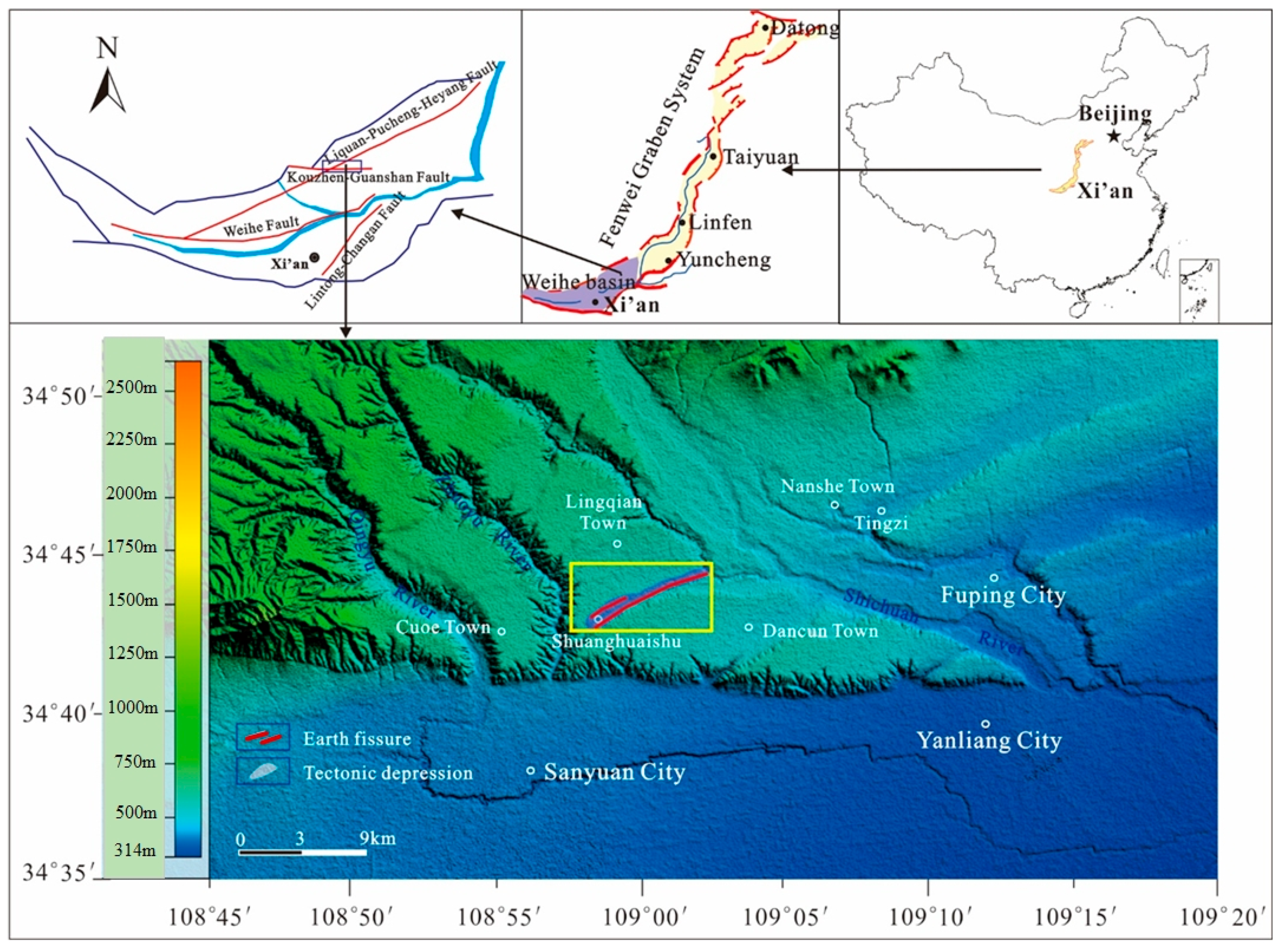
Figure 1. Geologic location of the Weihe Basin (modified from Peng et al., 2018 [4]).
Water 15 02321 g001
Figure 2. Typical photos and detailed characteristic of the main fissures (modified from Peng et al., 2018 [4]).
Water 15 02321 g002
Figure 3. Precipitation histogram of Sanyuan from 2000 to 2015.
Water 15 02321 g003
Figure 4. Coupled DEM-CFD numerical model (modified from Wang et al., 2022 [20]).
Water 15 02321 g004
Figure 5. Relationship between problem and numerical method.
Water 15 02321 g005
Figure 6. Model diagram: (a) frontal dimensions; (b) overall morphology and particle distribution; (c) fluid distribution; and (d) location of bottom seepage points.
Water 15 02321 g006
Figure 7. The beginning stage of hidden holes: (a) the displacement distribution and contact force network of sand; (b) the displacement distribution and contact force network of clay.
Water 15 02321 g007
Figure 8. The ending stage of hidden holes: (a) the displacement distribution and contact force network of sand; (b) the displacement distribution and contact force network of clay.
Water 15 02321 g008
Figure 9. The beginning stage of an arch: (a) the lateral and top displacement distribution of sand; (b) the lateral and top displacement distribution of clay.
Water 15 02321 g009
Figure 10. The ending stage of an arch: (a) the lateral and top displacement distribution of sand; (b) the lateral and top displacement distribution of clay.
Water 15 02321 g010
Figure 11. The stages of a sinkhole: (a) the displacement distribution of sand; (b) the displacement distribution of clay.
Water 15 02321 g011
Figure 12. The stage of horizontal extension: (a) the displacement (arrow) distribution of sand; (b) the displacement (arrow) distribution of sand clay.
Water 15 02321 g012
Figure 13. The ending stage of horizontal extension: (a) the displacement distribution of sand; (b) the displacement distribution of clay.
Water 15 02321 g013
Figure 14. Ground fissure outcropping process caused by strong erosion effect of heavy rainfall: (a) subsurface erosion into hidden hole; (b) traction into arche; (c) collapse into sinkhole; and (d) horizontal extension (modified from Wang et al., 2019 [5]).
Water 15 02321 g014
Table 1. Input parameters to numerical model.
TypeParametersValue
SolidMaximum particle diameter (m)0.005
Minimum particle diameter (m)0.001
Particle density (g/cm3)2600
Normal stiffness (N/m)1.0 × 106
Shear stiffness (N/m)1.0 × 106
(CB) Tensile strength (N)1.0 × 101
(CB) Shear strength (N)5.0 × 101
Friction coefficient0.5
FluidFluid density (kg/m3)1000
Fluid viscosity (Pa·s)0.1
Disclaimer/Publisher’s Note: The statements, opinions and data contained in all publications are solely those of the individual author(s) and contributor(s) and not of MDPI and/or the editor(s). MDPI and/or the editor(s) disclaim responsibility for any injury to people or property resulting from any ideas, methods, instructions or products referred to in the content.