Article

Experimental Study on the Wake Characteristics of Composite Secondary Grooved Cylinder

1
Shanghai Marine Diesel Engine Research Institute, Shanghai 201108, China
2
National Engineering Research Center of Special Equipment and Power System for Ship and Marine Engineering, Shanghai 201108, China
3
School of Mechanical Engineering, Jiangsu University of Science and Technology, Zhenjiang 212000, China
*
Author to whom correspondence should be addressed.
Water 2023, 15(11), 2073; https://doi.org/10.3390/w15112073
Submission received: 19 April 2023 / Revised: 24 May 2023 / Accepted: 24 May 2023 / Published: 30 May 2023
(This article belongs to the Section Hydraulics and Hydrodynamics)

Abstract

:
Flow around cylinders is widespread in marine engineering projects such as marine risers, marine pipelines, and tension leg. To understand the wake characteristics of the circular cylinder with different roughness, at a Reynolds number of 7400, a circulation water tunnel is used for experimental PIV measurements to compare the wake characteristics among the smooth cylinder, the original grooved cylinder, and the secondary grooved cylinder. The results revealed that the secondary grooved reduced the recirculation region, the flow-direction velocity gradient, the Reynolds shear stresses, and turbulent kinetic energy. Both small-scale and large-scale vortices are present in the wake vortex shedding. The instantaneous large-scale vortices behind the grooved cylinders are dispersed into several relatively small-scale vortices. Furthermore, the spike of the secondary grooved cylinder is a vortex generator, and directly impacts the generation of small eddies and the dissipation of large vortices.

1. Introduction

As a classical physical phenomenon of the flow around a blunt body, the flow around a cylinder exists widely in nature, and has an important influence on ocean engineering. The flow around a cylinder exists in ocean risers, pipelines, and tension-leg platforms. Vortex shedding often occurs in the cylindrical wake, which aggravates the problems of resistance, lift fluctuation, structural vibration, and noise [1,2]. Many scholars have adopted passive devices on the cylinder surface to limit the adverse effects of a positive pressure gradient on the boundary layer. In the past, the commonly used vortex suppression devices included the fairing structure [3,4], tabs [5], and the rigid splitter plate [6,7,8], which have also been proven to be extremely effective. These studies indicated that the fairings could alter the flow around the profile, directly shifting the separation point of the boundary layer and narrowing the wake. The rigid splitter plate divides the wake into two regions; so that the upper and lower shear layers cannot interact with each other, thus suppressing the development of vortices to a certain extent [9]. However, the fairings and the rigid splitter plate are only suitable for specific environments, which may not therefore achieve the optimum drag reduction effect.
In contrast, the groove surface is more effective in reducing drag [10]. The influence of the groove’s depth, number, and shape on the wake characteristics and the wake mechanisms of the grooved cylinder has been studied. For example, Afroz and Sharif [11] studied the laminar cross-flow over a smooth cylinder with three types of longitudinal grooves (triangle V-shaped, U-shaped, and rectangular grooves, respectively) at Reynolds numbers of about 200 and 300. They found that the average drag coefficient of the U-shaped groove structure significantly decreased by 13% and 10%, respectively. It was found that increasing the width and depth of the grooves could reduce the critical Reynolds number [12], and also that the spikes of the grooves are able to reduce the turbulent kinetic energy in the near wake region [13]. Additionally, it was then discovered that the boundary layer separation points gradually move to the rear edge of the cylinder as the surface roughness height increases [14]. Aleksyuk [15] numerically studied the evolution of three-dimensional perturbation, and thought the mainly destabilizing effect is related to the shear deformations and stretching. In addition, through numerically analyzing the vortex oscillations of the cylinders with different roughness, it was found that the surface roughness of cylinders suppressed the formation of wake vortex patterns [16].
Over the last two decades, particle image velocimetry (PIV) has been widely used in flow field research due to its high accuracy, capacity for 3D velocity, and instantaneous measurements [17]. Hwang [18] investigated the effects of three helical grooves on vortex-induced vibrations of an elastically supported cylinder and a fixed cylinder. A 64% decrease in peak amplitude and a significant reduction in the transverse vibration caused by the vortex were observed. Moreover, in the range of subcritical Reynolds numbers, the spiral groove can reduce the cylinder’s resistance in water by about 25%. Canpolat [19] revealed the flow characteristics of cylindrical wake, and particle image velocimetry (PIV) was used to study the flow control mechanism of a single groove on the cylindrical surface. Talley and Levy studied the effects of cactus-inspired grooved cylinders and spines and found that the spike of grooves were able to reduce the fluctuating kinetic energy [20,21]. Qi [22] investigated the impact of the depth of the V-groove on the drag and wake structure. It was found that the depth of V-shaped grooves exhibits a good drag reduction effect, which can achieve a drag reduction rate of 16% and reduce the vortex shedding frequency. As well as the impact of the depth of these grooves, the effect of the number of grooves on the multi-scale wake structure was also studied. The results revealed significant vortex oscillations occurring behind the grooved cylinder on small scales, and the vortex turning closer to the rear edge of the cylinder on a large scale [23].
The surface microstructures of many organisms reduce drag, such as the surface structure of sharks and birds’ feathers [24]. The surface structure of organisms provided an excellent research direction for the investigation of drag reduction, and by studying the mechanisms of drag reduction in these biological structures, new structural forms can therefore be designed [25]. Many scholars designed a series of single-scale grooves according to the drag reduction principle of the biological surface structure. They obtained a specific drag reduction effect through experiments and numerical simulation calculations [26]. Further research revealed that sharks can swim fast in water due to the small groove-like structures present on their surfaces. These tiny grooves have a variable structure and can reduce drag while swimming [27]. Based on this inspiration, a small-scale groove structure with the same shape was added on both sides of the original groove. This bionic shark-skin structure was considered to be the design of the secondary groove structure; this study is the first time a flow metric has been applied to the cylinder surface to study its wake characteristics. Therefore, this paper examines the smooth cylinder, the original groove, and the secondary groove cylinder, and compares the effects of the groove spikes on the wake structure. It provides theoretical support and a practical basis for the application of marine structures and is conducive to improving their safety and stability. Therefore, the secondary groove structure is an essential objective of this study.
This study aimed to assess the wake thickness and characteristics of a smooth cylinder, the original grooved cylinder, and the secondary grooved cylinder in the flow direction plane and the spanwise plane with particle image velocimetry (PIV) technology. The time-averaged streamlines, time-averaged velocity, Reynolds shear stress, turbulent kinetic energy, and spectral characters of the wake were used to compare the flow field behind the cylinders.

2. Experimental Apparatus and Details

2.1. Experimental Models

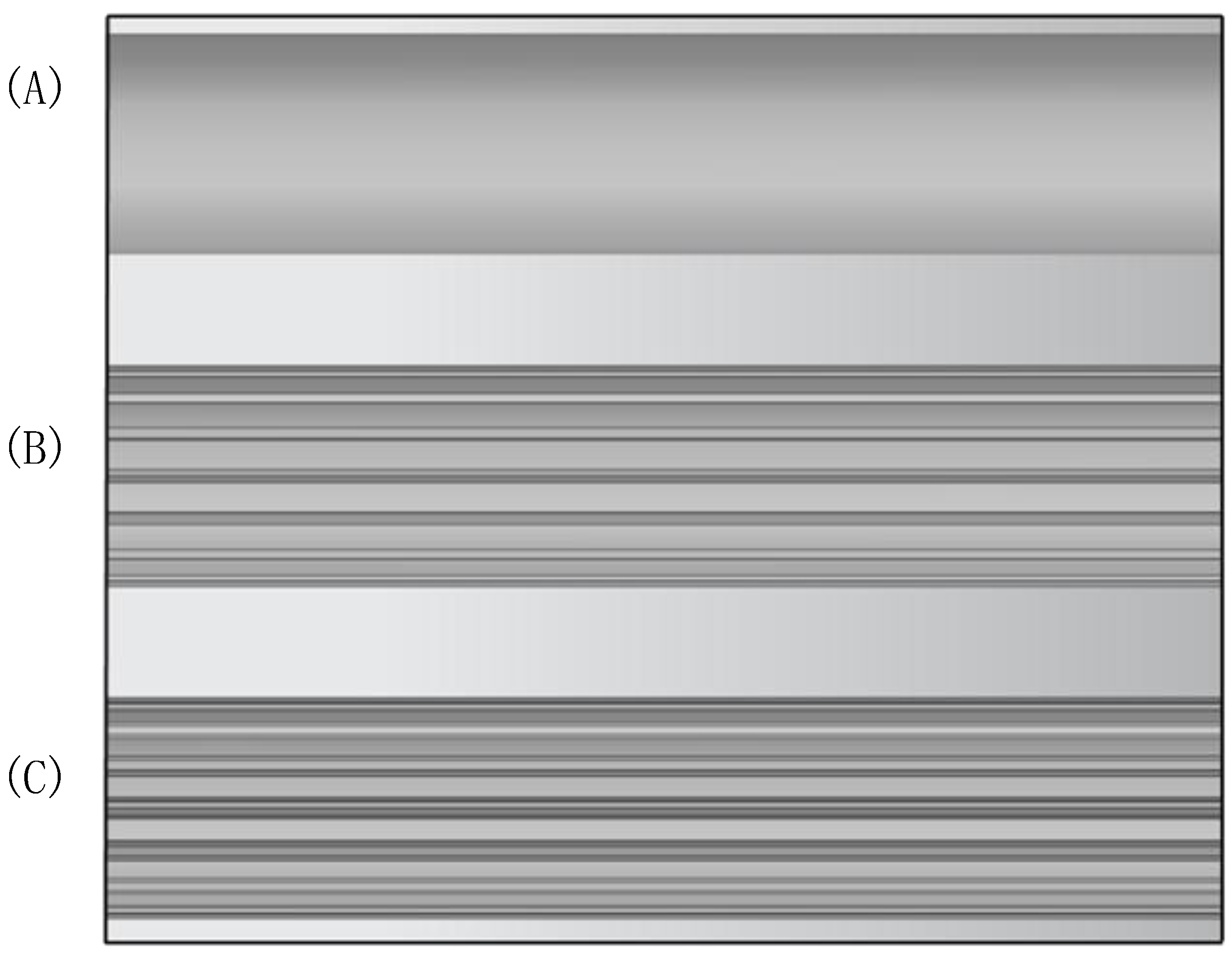
To investigate the influence of the secondary groove structure, the smooth cylinder, the original grooved cylinder, and the secondary grooved cylinder were compared. The 3D printer containing the PVC material produced three cylinders, and the cylinders were all coated with black paint to avoid reflecting laser light. As shown in Figure 1a, the three cylinders’ diameter (D) was 20 mm, while the length (L) was 300 mm, respectively. Figure 1b shows a cross-section of the original slotted cylinder with 16 triangular grooves evenly distributed on the surface of the cylinder; the angle of the grooves was 60°, the depth of the grooves (k) was 1 mm, and the surface roughness coefficient (k/D) was 0.05, respectively. Figure 1c depicts a cross-section of a secondary grooved cylinder with the secondary grooves designed following the shark epidermal structure, adding grooves with a depth of 0.35mm and an angle of 60° on either side of the triangular grooves. Takayama and Aoki [28] studied grooved cylinders with k/D = 0.0175, while Zhou et al. [29] researched the grooved cylinder with a roughness coefficient of 0.05. This paper combined the groove depth of 1 mm (k/D = 0.05) for the central groove and 0.35 mm (k/D = 0.0175) for the secondary groove, which is similar to the groove-like structures of different scales on the surface of sharks. The length-to-diameter ratio of the experimental model (L/D = 15) was considered large enough to reduce the influence of the three-dimensional turbulence characteristics behind the cylinder [30]. It is worth noting that there are two main differences between the secondary groove and the original V-groove. The first is that the secondary groove construction adds two minor grooves on either side of the V-groove, and the second is that the secondary groove adds two spikes on either side of the V-groove.

2.2. Experimental Measurement Apparatus

The experiment was carried out in the circulating water channel, which includes a water pump, rectification device, steady flow section, test section, flow meter, three-phase asynchronous motor, PLC control cabinet, etc. The function of the rectification device is to ensure that the flow into the test section was a constant field flow; the test section of the tank was a rectangular body of 0.3 × 0.4 × 1 m3, and the three sides of the test section consisted of 10 mm thick transparent glass for laser illumination and high-speed camera filming. During the test, the PLC control cabinet controlled the motor’s start, stop, and power to achieve the speed adjustment of the water flow.
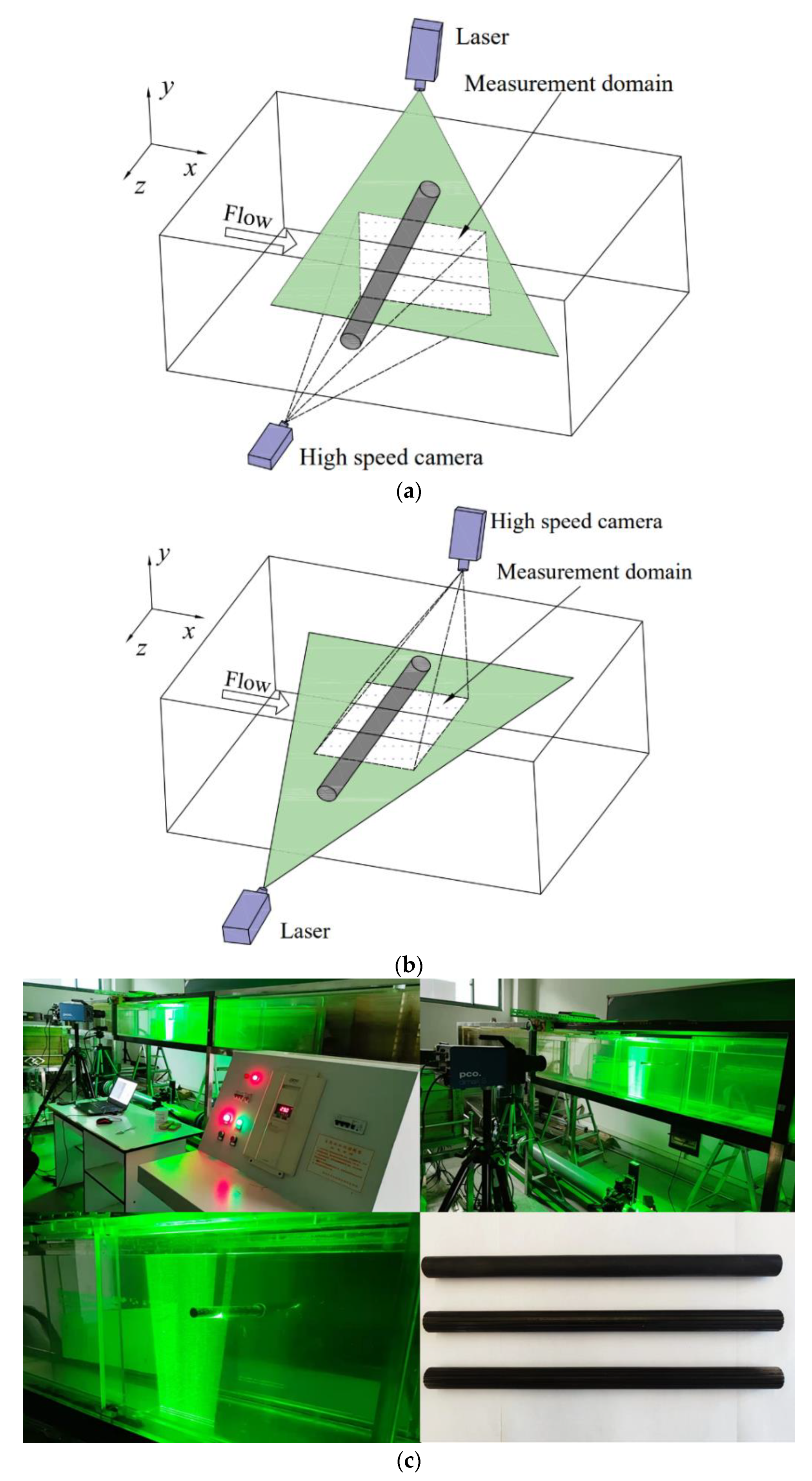
The Reynolds number is calculated by Re = ρ v L / μ , where ρ means the fluid density; v is the flow velocity; and μ represents the dynamical viscosity coefficient. The characteristic length scale (L) for this experiment was 20 mm. The flow quantity (Q) during the test was 160 m 3 / h , the cross-sectional area (S) was 0.12 m 2 , and the flow velocity was 0.37 m/s, respectively, which corresponds to the Reynolds number (Re) of 7400. In the critical Reynolds number range, the Reynolds number has little effect on the cylindrical wake [31]. Figure 2a, b presents the measurement domain in the streamwise and the spanwise planes. It also shows the arrangement of the laser and camera; the measurement domain is always in the middle of the water channel. The cylinder was placed in the middle between the water floor and the free surface. Caliskan et al. [32] studied the effect of the gap ratio on the flow passing a grooved cylinder near the wall. When the gap ratio was C/D > 0.6 (where C is the distance between the floor and the free surface, and D is the cylinder diameter), the shear flow near the wall was found to have no effect on the wake structure of the cylindrical bypass flow. Therefore, the effect of near-wall shear flow was ignored in this study.
Figure 2c displays the PIV measurement layout and the three experimental models. The PIV system mainly consists of a continuous laser, tracer particles, and a high-speed camera, etc. The working principle of the PIV system: tracer particles are added to the water flow, the plane to be detected is irradiated by an external light source, and after the tracer particles are considered to be sufficient to reflect the velocity field change, the images are captured by a camera, and finally, the particle displacement between the adjacent images is calculated to obtain the velocity vector of the flow field. The laser used in this experiment was a continuous semiconductor laser of type GT1 + 11 A, with an output power of 2 W, and a laser wavelength of 532 nm, respectively. The camera model used in this study was the PCO.dimax S1 (1008 × 1008 pixels) with a Nikkor 24–85 mm f/2.8 lens, capturing 2000 consecutive digital particle images at 1 ms intervals, i.e., a frame rate of 1000 fps, with the shutter speed (exposure time) set at 1.5 μs per frame.
This measurement was conducted twice to eliminate experimental error. This paper extracted the displacement vectors of two consecutive frames according to the correlation analysis method, and then subjected them to a mutual correlation calculation. To improve the image accuracy and increase the signal-to-noise ratio, a deformable multiple grid iteration algorithm was used, which gradually obtains higher resolution and higher accuracy velocity fields by reducing the window size and window interval layer-by-layer; the PIV measurement accuracy in this paper was about 0.2 mm/pixel for the pixel size and 1.5 mm for the velocity vector spatial resolution, respectively. The error vector detection function can be defined as U m e a n U i , j / U m e a n < 40%, where U m e a n is the mean value of the surrounding eight vectors. In cases where the error vector was detected, it was replaced by the average of the surrounding vectors for correction.

3. Experimental Results and Discussion

3.1. Streamlines and Velocity Field

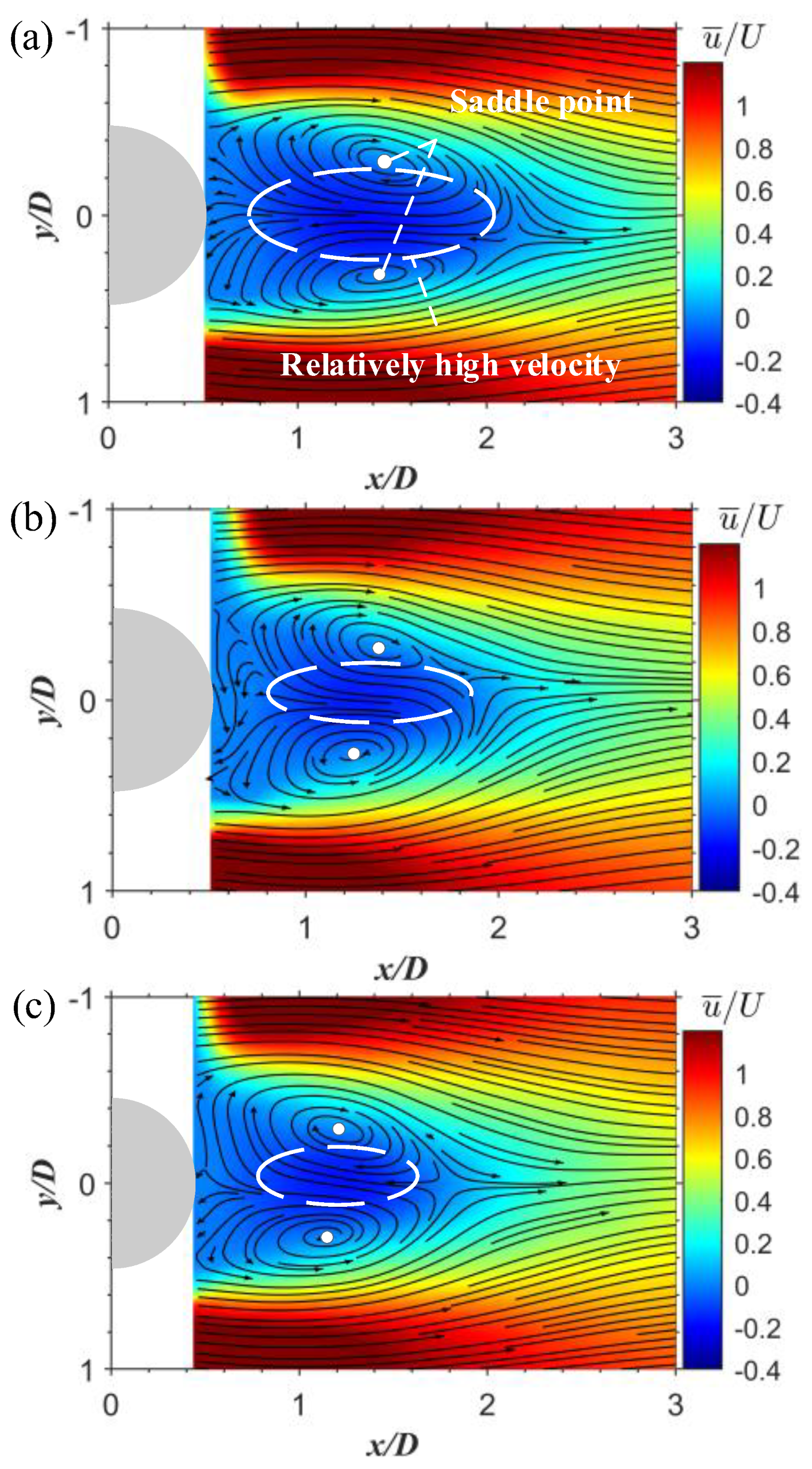
Figure 3 compares a pair of vortices and the recirculation region on the near wake in the (x, y)-plane of z = 0 for the smooth, the original grooved, and the secondary grooved cylinders. For each case, a pair of reversed vortices behind the cylinder was deemed to be a typical feature of boundary layer transitional motion; the vortex-induced vibration can be weakened by weakening the interaction of the separated shear layer. In other words, the vortices in the near wake region are crucial for reducing vortex induced vibrations. Therefore, it was necessary to study the effect of the secondary grooved cylinder during the transitional motion on the near wake structure. Liu et al. [33] defined the length and the width of the recirculation region as the distance from the center of the circular cylinder to the saddle point, and the distance between the two saddle points in the streamlined pattern. The width of the recirculation region of the smooth cylinder, the original grooved cylinder, and the secondary grooved cylinder were found to all be around 0.6 D. The length of the recirculation region of the smooth, the original grooved, and the secondary grooved cylinder were determined to be approximately 1.5 D, 1.3 D, and 1.2 D, respectively, as shown in Figure 3. The length of the recirculation region in the original grooved cylinder and the secondary grooved cylinder compared to the smooth cylinder was reduced by 13% and 20% respectively. Comparing the recirculation length on the near wake revealed that the largest wake recirculation area was behind the smooth cylinder, while the smallest wake circulation area was located in the secondary groove’s wake. Overall, these results indicated that a secondary groove cylinder could reduce the size of the recirculation.
Incorporating the spikes into these cylinders causes the formation of small vortices, and breaks the large vortices as a result [34]. Comparing the velocity circulation regions of the smooth cylinder, the original grooved, and the secondary grooved cylinders, the velocity circulation region after the secondary grooved cylinder was found to be slightly smaller. Considering the reasons for this, it has been believed that the spikes on either side of the original grooved cylinder induce a boundary layer transition, thereby affecting the wake structure during the bypass [35]. From the above results (shown in Figure 3), it is evident that the wake of the groove structure improved the wake structure of the cylinder recirculation area, particularly for the secondary groove structure, which has been associated with reducing the drag for the cylinder [36].
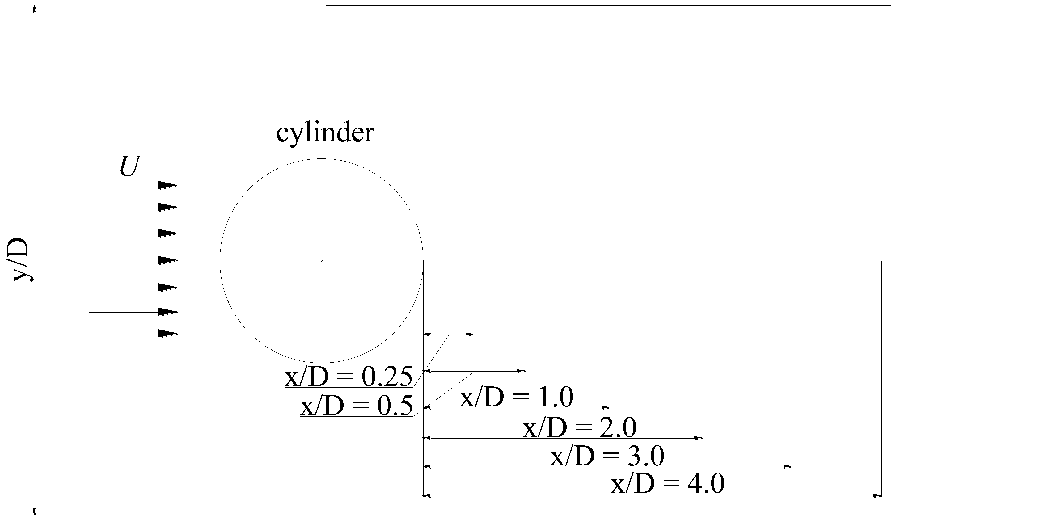
Figure 4 provides a schematic of the extraction position for the velocity profile. To investigate the detailed information regarding the velocity lag and velocity gradients on the near wake, the wake velocity profiles of six locations were extracted for stability analysis [37].
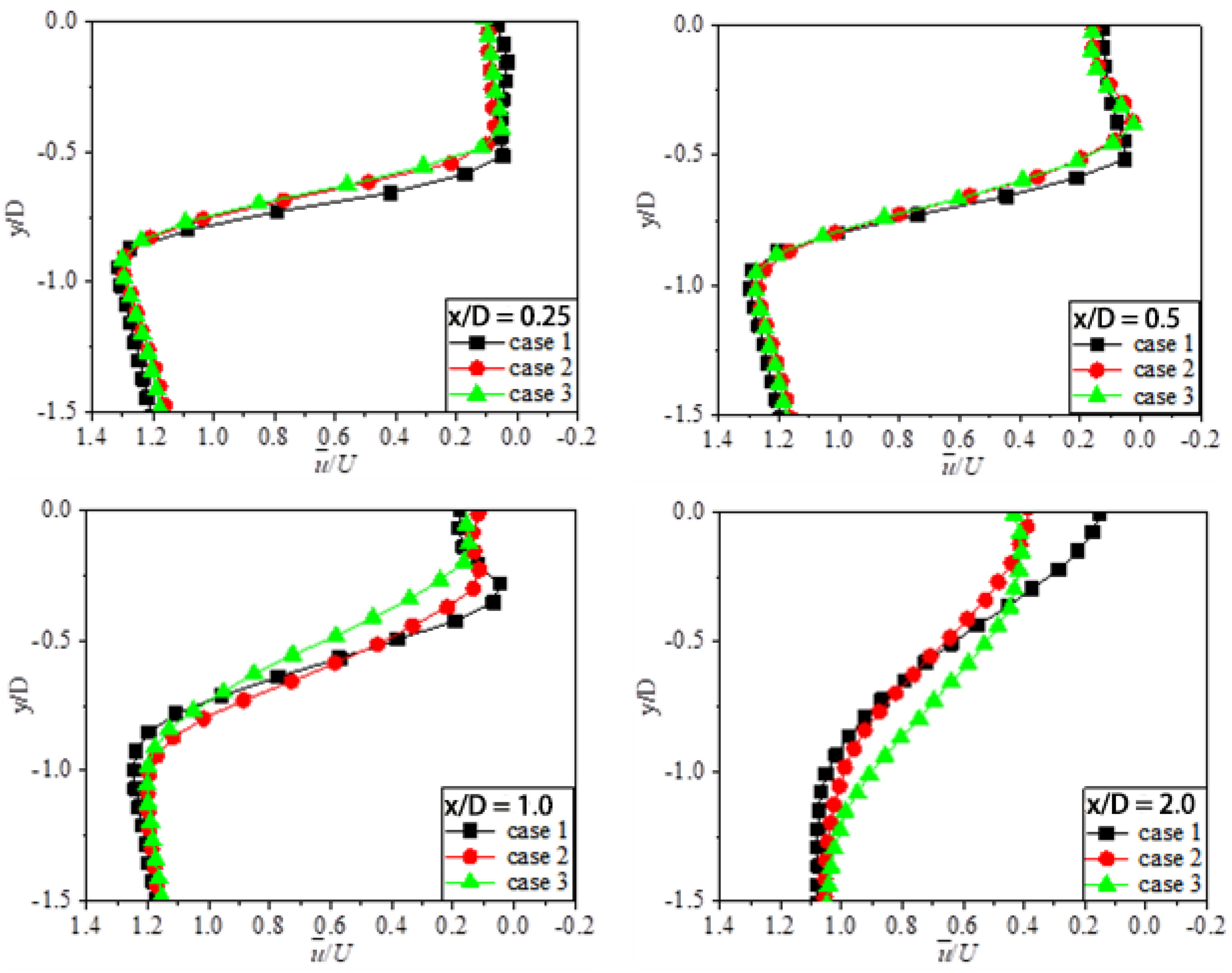
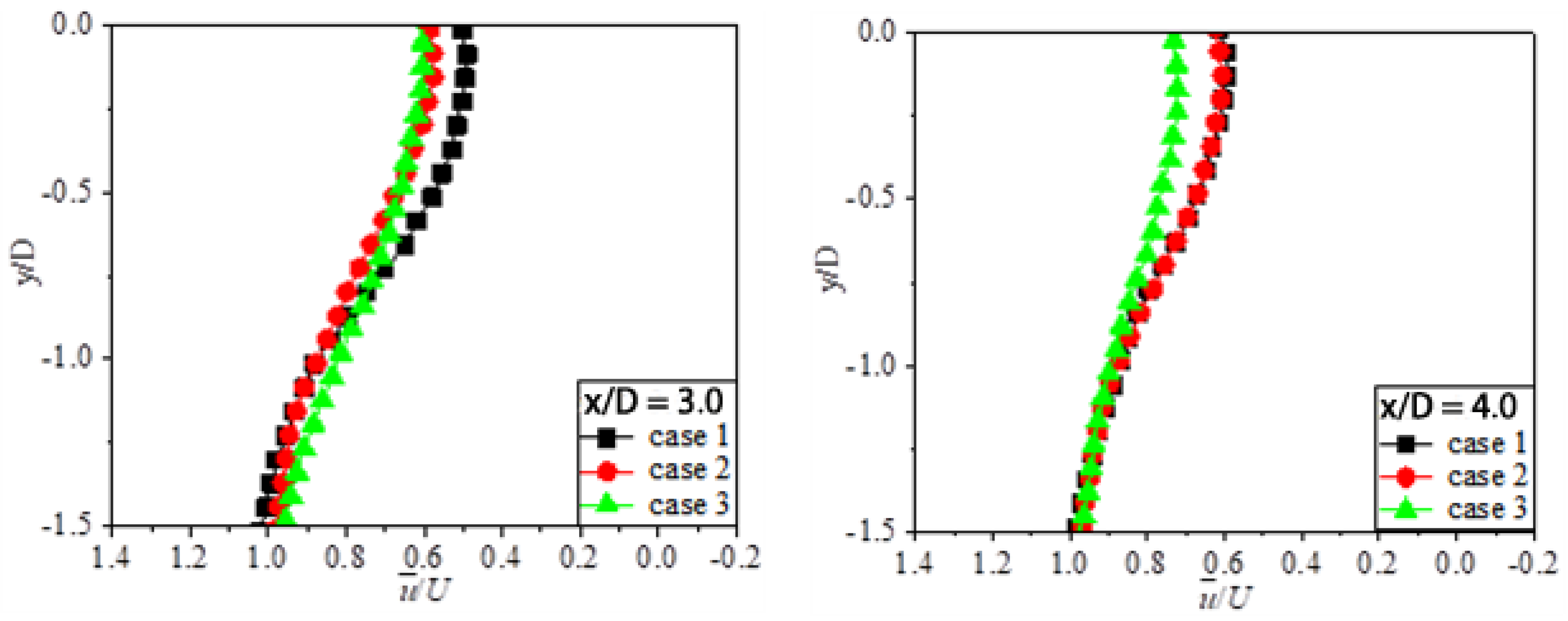
Figure 5 plots the time-averaged streamwise velocity profiles of the smooth cylinder (case1), the original grooved cylinder (case2), and the secondary grooved cylinder (case3) for the six locations of the streamwise (x/D = 0.25, 0.5, 1.0, 2.0, 3.0, and 4.0, respectively) in the (x, y)−plane. Half of the averaged velocity was plotted due to its symmetric distribution around the center line of y/D = 0, as shown in Figure 5.
In the near wake region (0 < x/D < 1), the velocity profiles can be divided into three sections in the y-direction: the blocking section, the transitional section, and the regular section. The blocking section indicates that at the section of u ¯ / U 0 , the velocity gradients of the regular section are almost zero, and the transitional section is defined as the transition between the blocking section and the regular section.
At the location of x/D = 0.25 and x/D =0.5, the minimum velocity of the smooth was found to be smaller than the original grooved and the secondary grooved cylinders in the blocking section. Meanwhile, the blocking section’s width of two grooved cylinders was smaller than that of the smooth cylinder. In the transitional section, the velocity gradient of the two grooved cylinders was smaller than that of the smooth cylinder due to the effect of reversed flow in the wake region. In particular, the velocity gradient of the original grooved cylinder was found to be larger than that of the secondary grooved cylinder. The width of the regular section (−1.5 < y/D < −0.9) of the three cases remained the same due to the same vicious force of the fluid that was present.
At the location of x/D =0.5, the variation of fluid velocity was found to be consistent with x/D = 0.25 at the regular section (−1.5 < y/D < −0.6). In the blocking section (−0.6 < y/D < 0), the width of two grooved cylinders was smaller than the smooth cylinder. In the transitional section, the velocity gradient of two grooved cylinders was also smaller than that of the smooth cylinder.
At the location of x/D = 1.0, the width of the blocking section and the velocity gradient of the transitional section decreased, with the width and the velocity gradient of the secondary grooved cylinder being the smallest. There was a relatively large velocity in the middle of the blocking section observed at the location of x/D = 0.5 and x/D =1. These results are consistent with the results discussed in the previous section.
It is worth noting that the velocity gradient decreased from x / D = 0.25 to 4.0 in the cylinder wake region, as shown in Figure 5; this indicates a gradual reduction in the blocking influence of the cylinder [38]. In addition, the velocity gradient of the grooved cylinder was found to be smaller than the smooth cylinder at the location of x/D = 2, x/D = 3, and x/D = 4, respectively. This is due to the small-scale vortices that formed inside the groove structure, meaning that the fluid-solid contact between the external fluid and the cylinder wall was transformed into the fluid-flow contact between the fluid and the small-scale vortices, which reduced fluid frictional drag [39]. Meanwhile, there was a tip structure (the apex angle of the groove) observed for the secondary groove, and the small-scale vortices inside the groove were also raised.
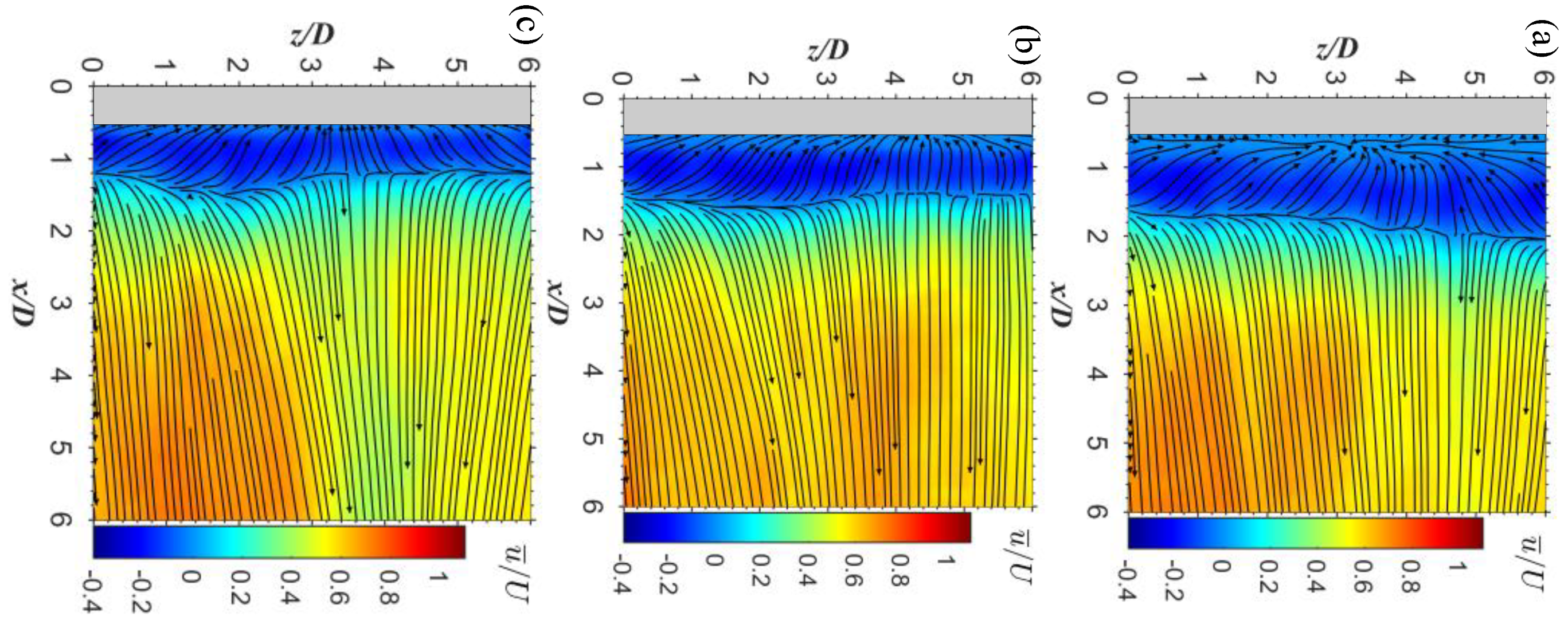
Figure 6 shows a comparison of the time-averaged streamline and the streamwise velocity contours between the smooth cylinder, the original grooved cylinder and the secondary grooved cylinder in the (x, z)-plane of y / D = 0 . For the smooth cylinder, as shown in Figure 6a, the blocking region and the turbulent dissipation region can be found on the wake according to the time-averaged streamline pattern. The blocking region is defined as a region of reversed flow that is nearly parallel to the smooth cylinder that can be distinctly observed, which is featured by negative streamwise velocity distribution within it. For the cases of grooved cylinders, as depicted in Figure 6b, c, the time-averaged streamlines and streamwise velocity displayed slight fluctuations in the spanwise direction. The length of the blocking region was approximately 1.4 D and 1.2 D, respectively. Compared with the smooth cylinder, the formation length of the grooved cylinder’s blocking region was reduced, while the secondary grooved cylinder’s length of the blocking region was found to be the smallest.
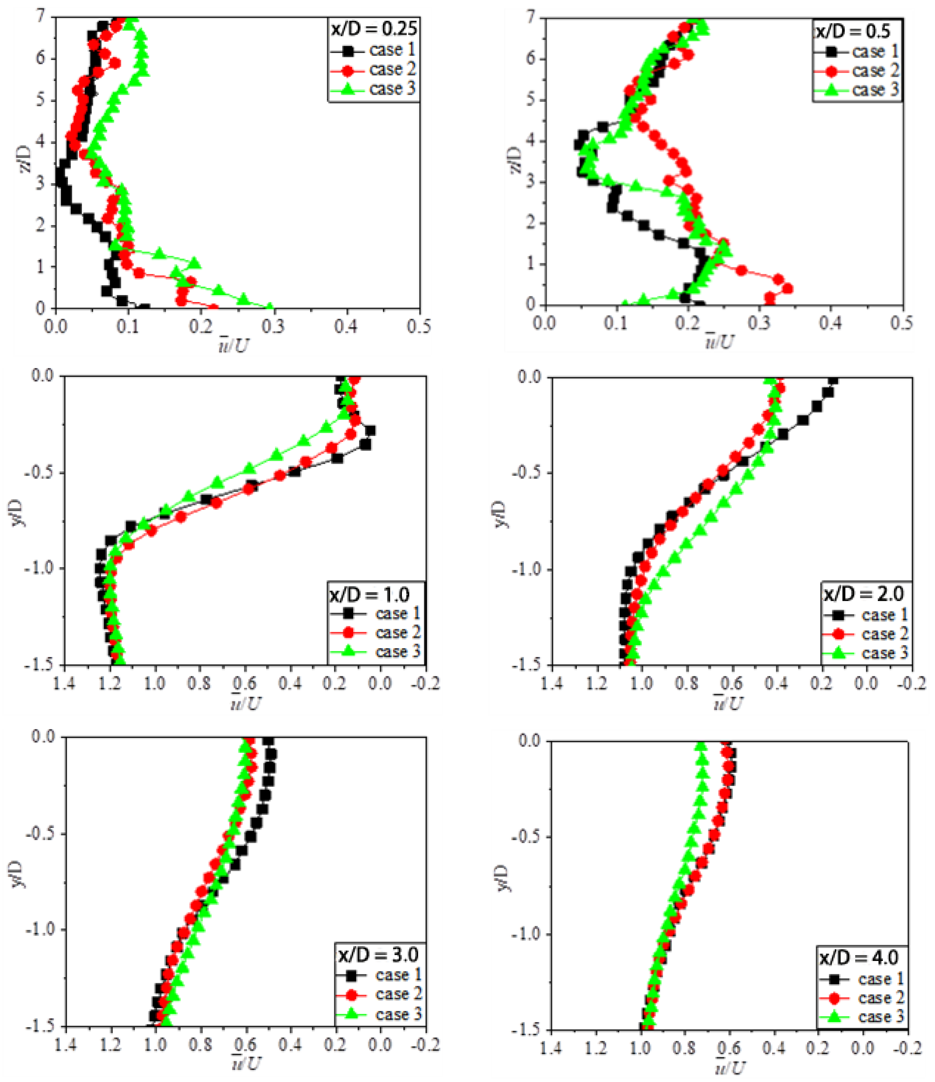
As shown in Figure 7, the time-averaged streamwise velocity profiles of the smooth cylinder (case1), the original grooved cylinder (case2), and the secondary grooved cylinder (case3) for the six locations of the streamwise in the (x, z)-plane was plotted. At x/D = 0.25 and 0. 5, the flow velocity was found to be relatively low, but fluctuated significantly. This was due to the fact that both locations were inside the blocking region. The velocity of the two grooved cylinders in the spanwise plane was faster than that of the smooth cylinder. In comparison, the secondary grooved cylinder’s spanwise velocity was found to be the fastest of the three cylinders.
As x/D increased from 0.25 to 0.5, the variation of the time-averaged velocity was also found to have increased, while the velocity fluctuations became larger for all three cases in the spanwise direction. At x/D = 0.5 and 1.0, respectively, the velocity fluctuation of the secondary grooved cylinder was the largest the among the three cases in the spanwise direction. At x/D = 2.0, the wake velocity was found to be half the speed of the incoming flow, while the velocity of the secondary grooved cylinder was determined to be larger than both the smooth and the original grooved cylinders. At x/D = 3.0 and 4.0, respectively, the spanwise velocity became stable, and the difference observed among the three cases vanished.

3.2. Reynolds Shear Stress and Turbulent Kinetic Energy

Viscous dissipation describes the consumption of turbulent momentum by fluid viscosity and its conversion into heat. In the case of flow around the cylinder, energy is transformed via two forms of fluid friction, namely form and viscous drags [40]. Reynolds shear stress is the additional stress on the mean flow caused by momentum exchange due to fluid fluctuation.
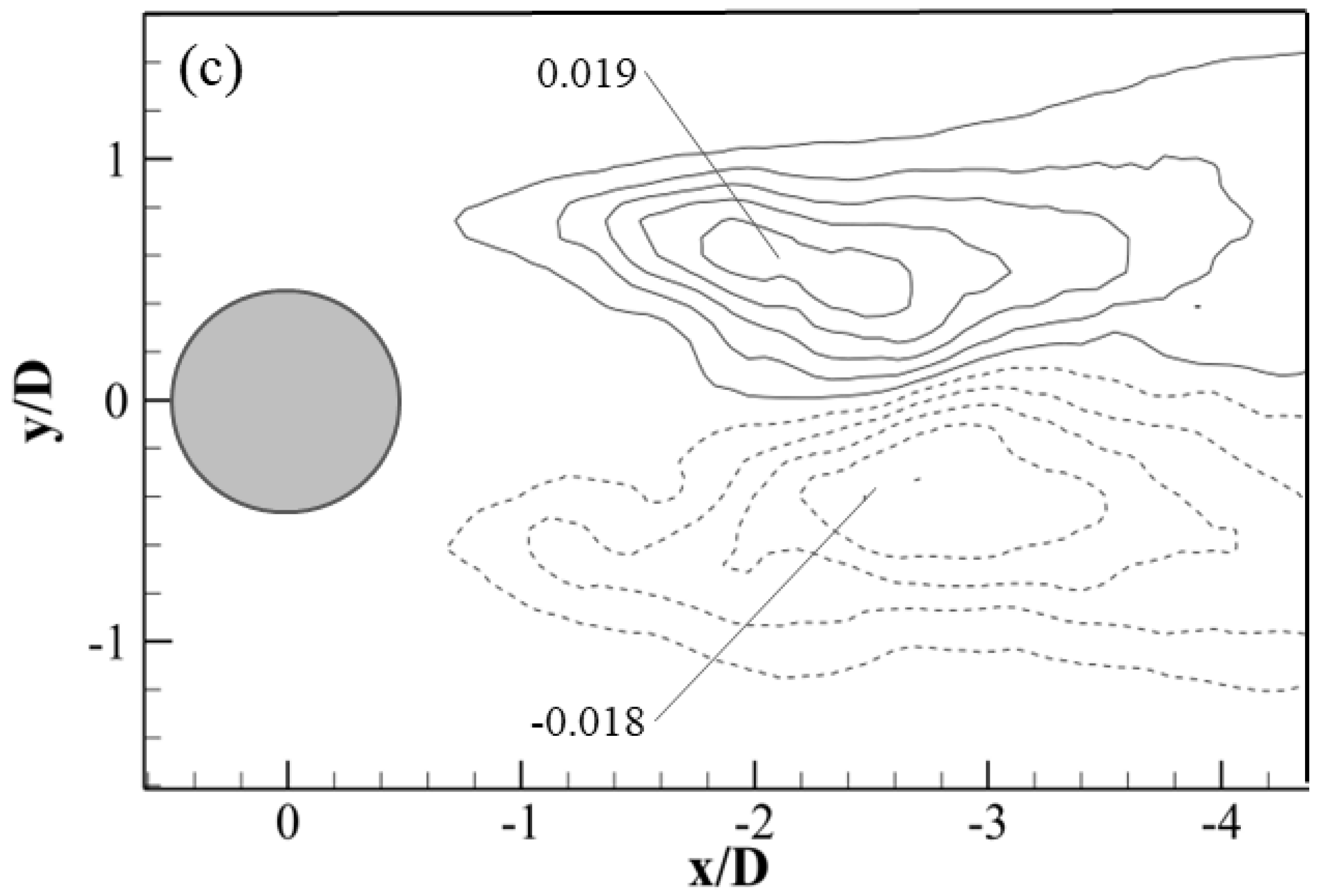
The contour of normalized Reynolds shear stress u v ¯ / U 2 for the smooth cylinder, the original grooved cylinder, and the secondary grooved cylinder in the (x, y)-plane is given in Figure 8. The maximum value of Reynolds shear stresses after the smooth cylinder was 0.026 and −0.028, the maximum value of Reynolds shear stresses after the original grooved cylinder was 0.023 and −0.022, and the maximum value of the secondary grooved cylinder’s Reynolds shear stresses was 0.019 and −0.018, respectively. Compared to the smooth cylinder, Reynolds shear stresses of the original and the secondary grooved cylinders reduced by about 5% and 7%, respectively. As the velocity gradient is proportional to the Reynolds shear stress, this demonstrates that the velocity gradient in the near wake region of the secondary groove cylinder was minimal. Meanwhile, the Reynolds shear stress was found to be smaller after both the original and secondary grooved cylinders than the smooth cylinder, indicating that the grooves reduce the viscous stresses within the boundary layer and thus reduce the shear stresses in the wake region. Furthermore, the Reynolds shear stress in the secondary groove was found to be less than that of the original groove, suggesting that the spike is reducing the Reynolds shear stress on the wake.
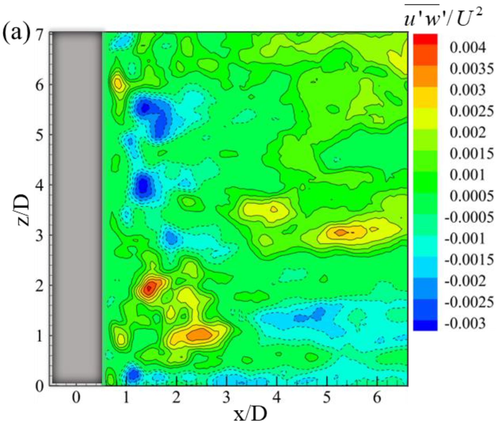
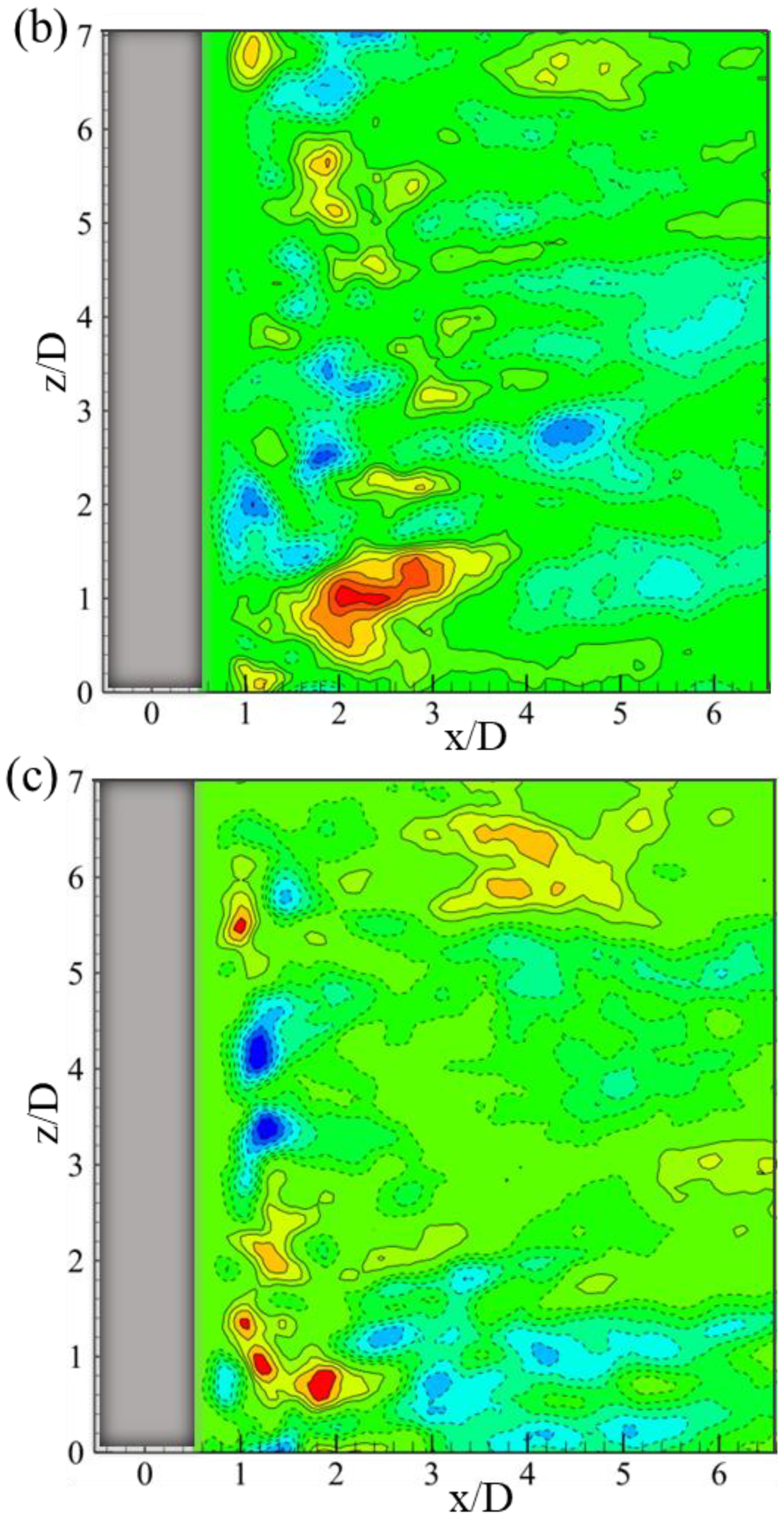
Figure 9 exhibits the distribution of the normalized Reynolds shear stress u w ¯ / U 2 for the smooth cylinder and with the grooved cylinders in the (x, z)-plane. For the smooth cylinder, the positive and negative Reynolds shear stress regions can be observed, as shown in Figure 9a, with the maximum positive and negative values of 0.004 (x/D = 1.5, z/D = 2) and −0.003 (x/D = 1.5, z/D = 4), respectively. In addition, the positive peak ( u w ¯ / U 2 = 0.03) of Reynolds shear stress was found at the location of x/D = 5.4 and z/D = 3. The maximum value of the original groove cylinder was about 0.03 (x/D = 2.2, z/D = 1), and that of secondary grooved cylinder was around 0.02 (x/D = 1.8, z/D = 0.6), respectively, as displayed in Figure 9b,c. The Reynolds shear stress of the grooved cylinder gradually decreased, and did not exhibit a significant region of high stress during the downstream movement of the wake. Compared with the smooth cylinder, the maximum value of Reynolds shear stress slightly decreased behind the grooved cylinders. This may imply the influence of the flow features from the grooved cylinders.
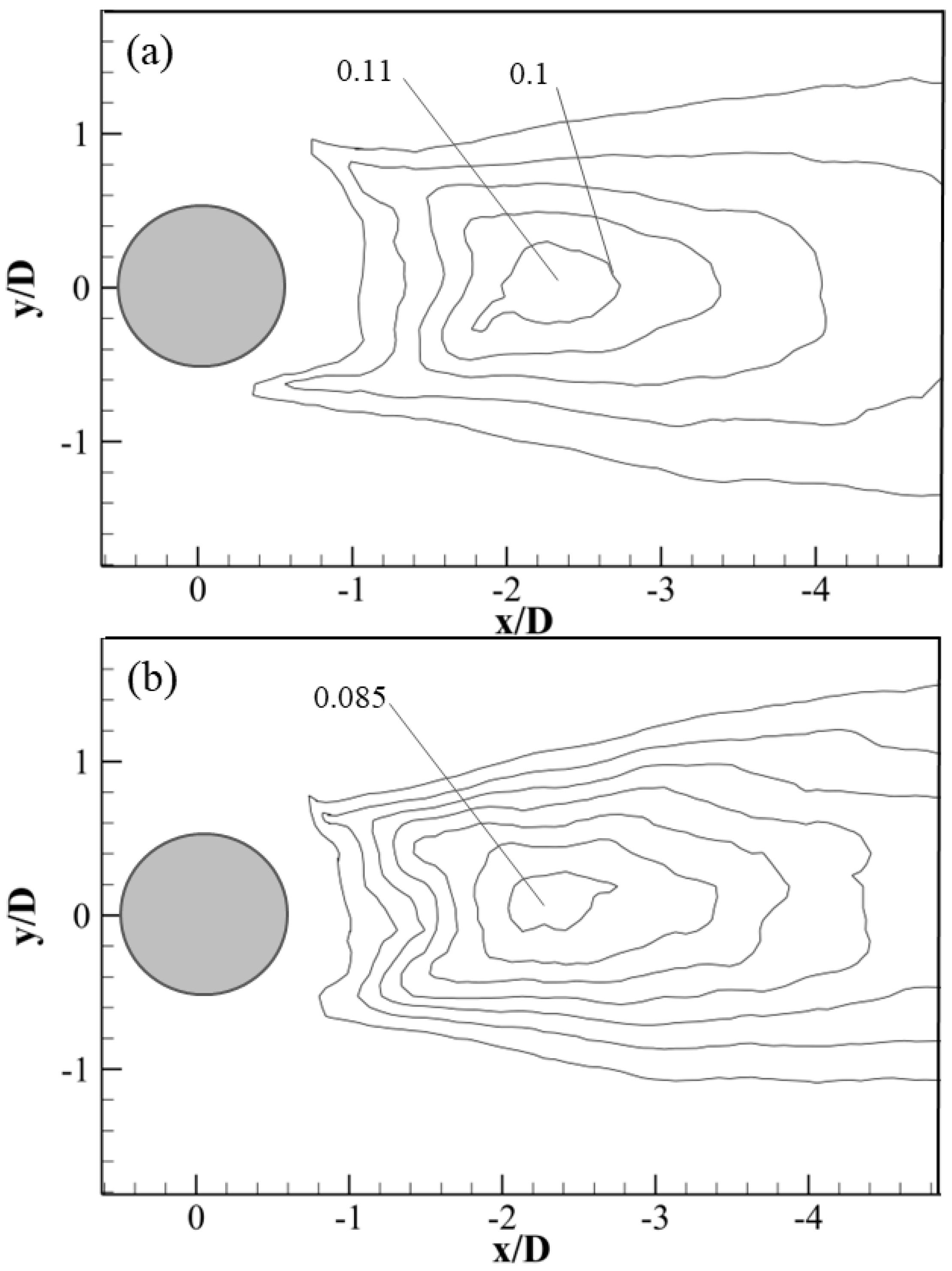
The role of turbulence energy is in the development or diffusion of the near wake behind the cylinder. Turbulent kinetic energy (TKE) is calculated as TKE = 0.75 ( u 2 ¯ / U 2 + v 2 ¯ / U 2 ) in the (x, y)−plane, and TKE= 0.75 ( u 2 ¯ / U 2 + w 2 ¯ / U 2 ) in the (x, z)-plane, respectively. It is used to study the energy loss and dissipation processes for the different grooved cylinders [41]. To analyze the effects of TKE distribution in the wake region, Figure 10 compares the distributions of the normalized TKE for the smooth cylinder and the grooved cylinders in the (x, y)-plane at z/D = 0. The turbulent energy was found to be concentrated in the region of vortex formation of the flow around the cylinder (D < x< 3 D). Furthermore, the turbulent energy in the blocking region was minimal, while the smooth cylinder’s turbulent energy in the blocking region was found to be larger than that of the original grooved and secondary grooved cylinders. The secondary cylinder’s turbulent energy in the blocking region was found to be the smallest, indicating that the secondary cylinder decreases the turbulent energy in the blocking region.
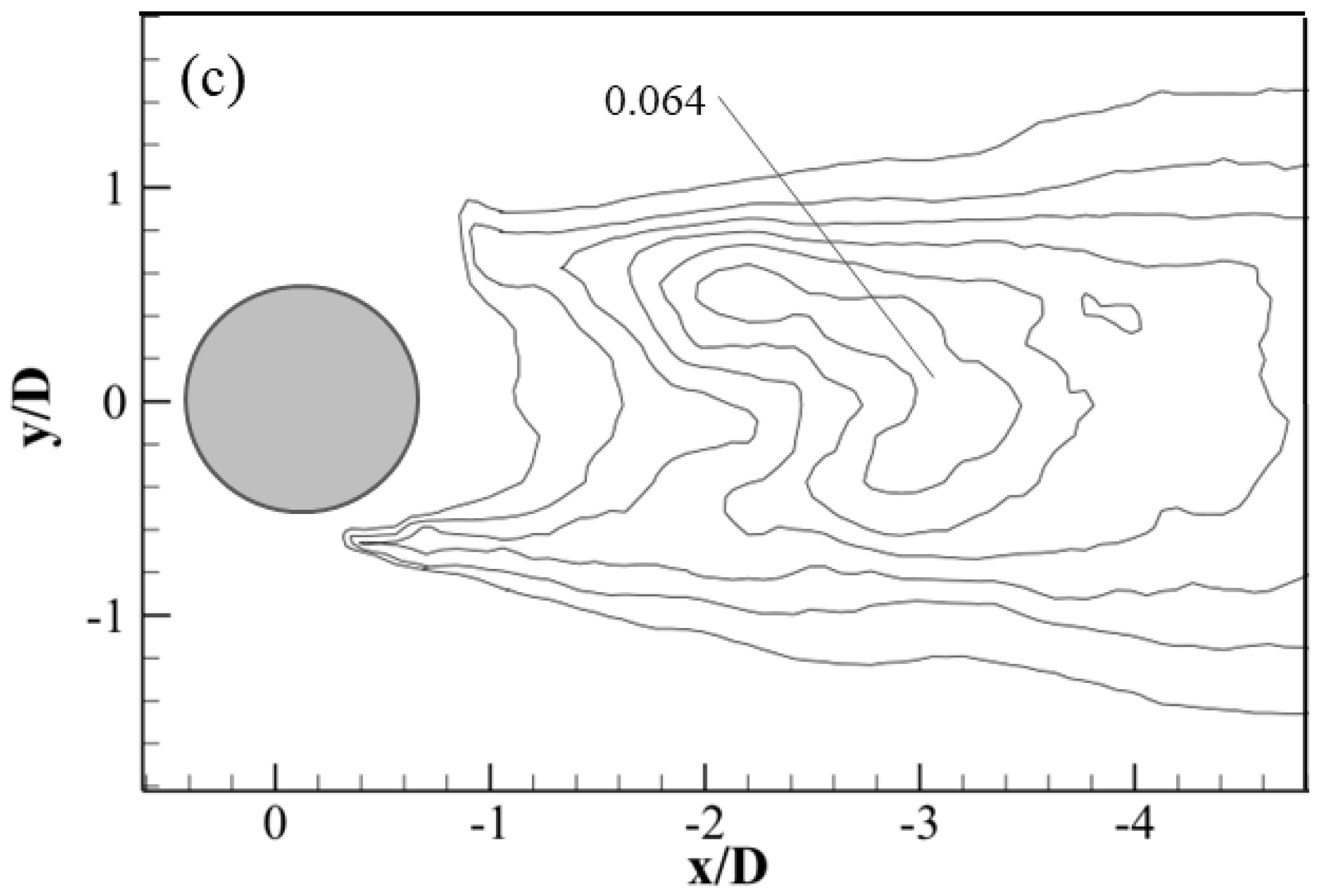
The maximum TKE of the smooth cylinder was around 0.11. However, the maximum magnitude of TKE for the original and secondary grooved cylinders were 0.085 and 0.064, respectively. Therefore, the TKE of the secondary grooved cylinder was found to be the minimum of the three cylinders, and the reduction rate was calculated to be 42% relative to the smooth cylinder. This indicates that the grooved cylinder appears to reduce the TKE in the wake regions. This may be due to the vortex formation being suppressed [42]. In addition, many small vortices were found to have formed in the boundary wall due to the secondary grooved cylinder’s tip structure, thereby decreasing energy consumption. The decrease of TKE may suppress vortex shedding in the near wake region, especially for the secondary grooved cylinder.
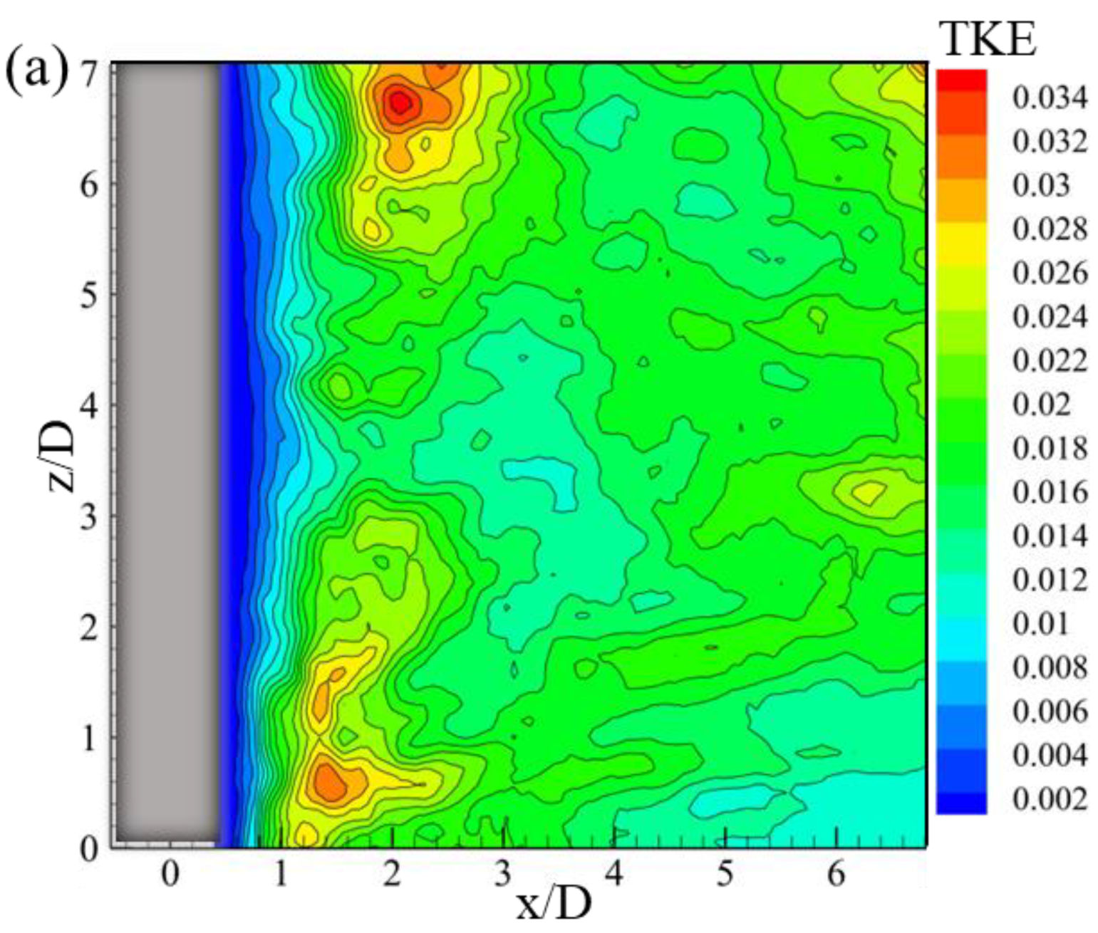
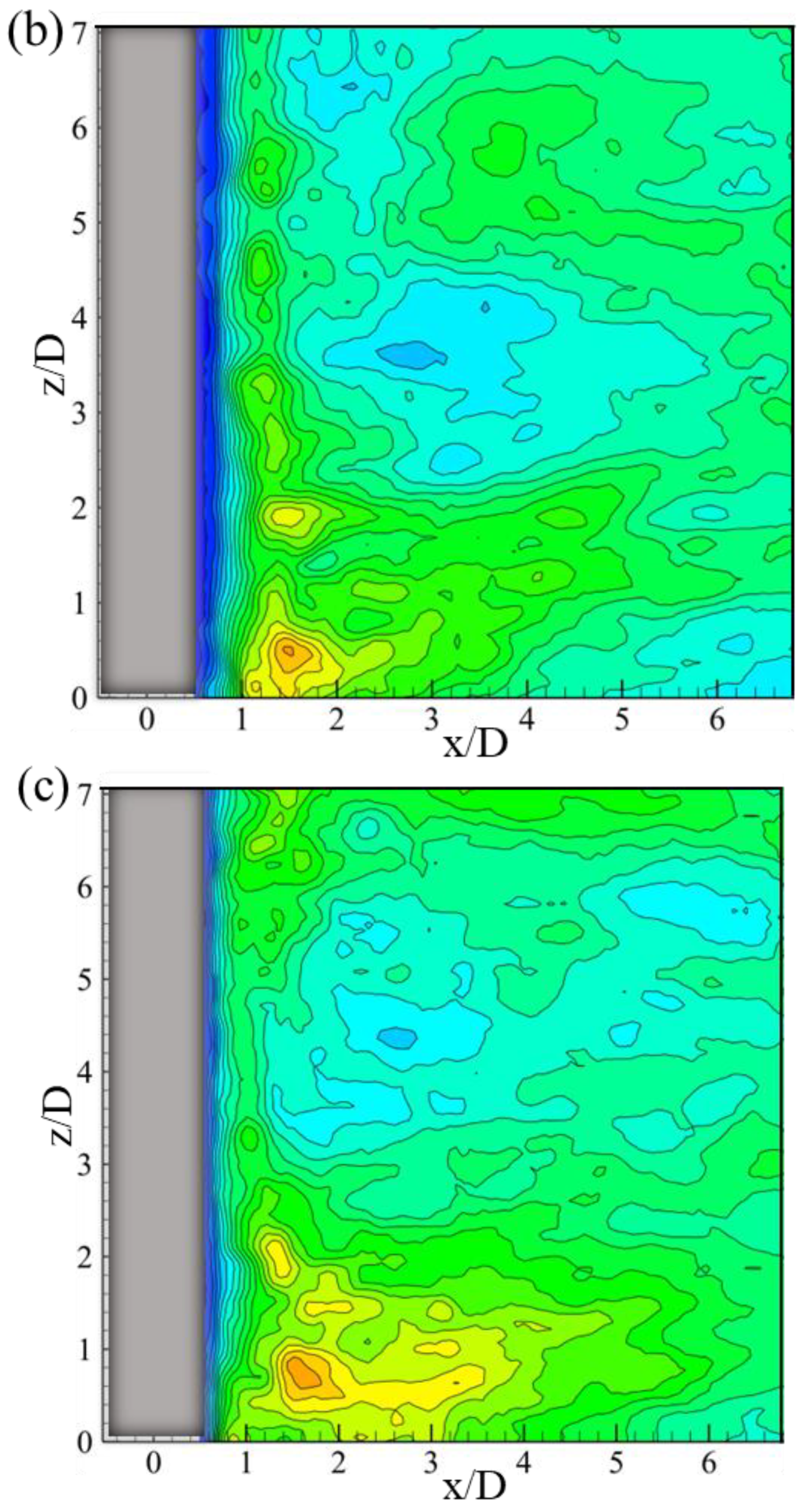
Figure 11 shows the normalized TKE distributions of the smooth cylinder, the original grooved cylinder, and the secondary grooved cylinder in the spanwise direction. The most significant turbulent kinetic energy clusters were distributed at the two ends of the spanwise direction, at 0.03 and 0.034, respectively (Figure 11a). For the grooved cylinders, the high turbulent kinetic energy region was concentrated only on the lower side, and the value of the maximum turbulent kinetic energy region was also 0.03 (Figure 11b,c). This confirms that the grooved cylinder is able to reduce the blocking region, and that the secondary grooved cylinder has the smallest blocking region. Furthermore, the area of the high turbulent kinetic energy region (TKE > 0.03) in the smooth cylinder’s spanwise plane was found to be the largest among the three models. This may be due to the vortex in the grooves and the secondary vortex structure generated by a spike. Additionally, further downstream ( x / D   > 3 ), vortex dissipation occurred, while the turbulent kinetic energy was also found to have rapidly decreased. In other words, the grooved cylinder suppresses turbulent fluctuations, thereby reducing turbulent kinetic energy. This is qualitatively supported by the result of TKE presented in Figure 10. Therefore, it is concluded that the decrease of Reynolds shear stress and the turbulent kinetic energy agree with the phenomenon of reducing the recirculation region by the grooved cylinder, as shown in Figure 3.

3.3. Spectral Characteristic

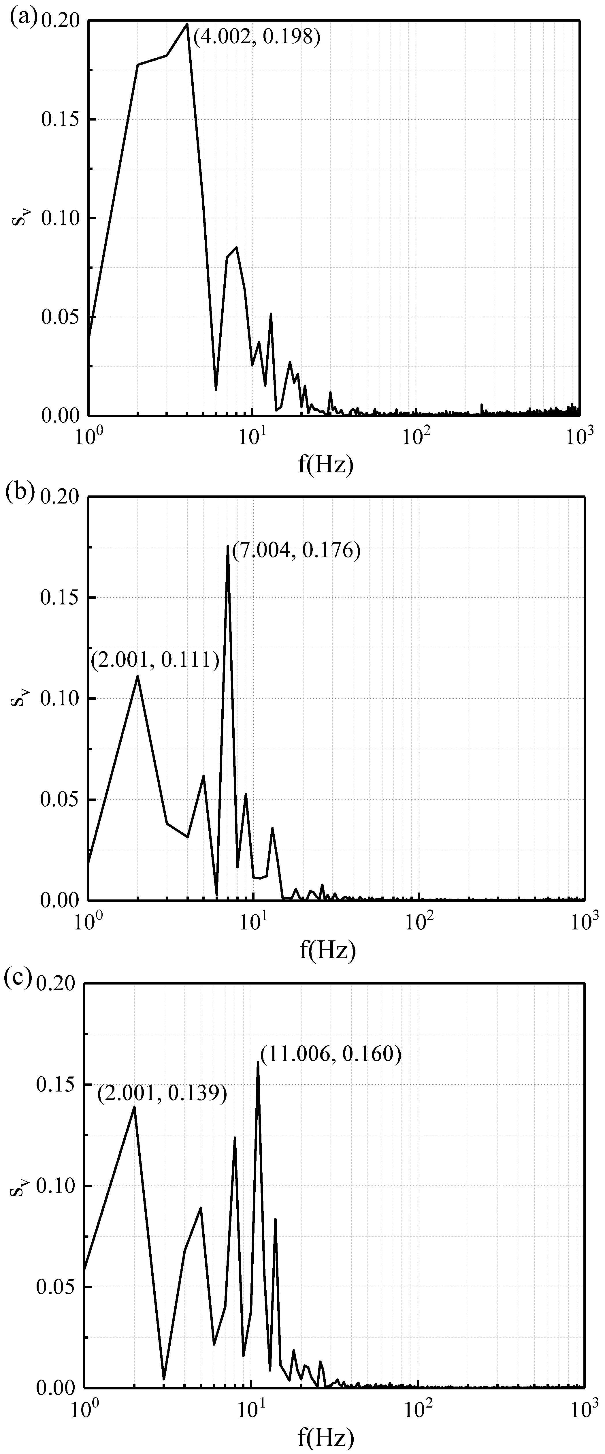
To further investigate the flow characteristic of cylindrical wake flow, the spectrum was calculated, and 2048 instantaneous data were selected from points near the vortex core for FFT transformation. At x / D   = 1.2 and y / D   = 0.6 , the spectrum S v of the velocity component u for all three cases was calculated. As shown in Figure 12a, the peak power spectrum on the smooth cylindrical tail has a frequency of 4 Hz and the Strouhal number can be expressed as S t = f D / U   = 0.21 , which is consistent with the results of Qi and Oruç [31,43]. The Strouhal44 number is the ratio of the inertial force of motion to the inertial force of a non-constant fluid and can be used to describe the flow state of a non-constant fluid. The Strouhal number was found to be relatively stable at the subcritical stage (300 ≤ Re < 3 × 10⁵).
In contrast, two large peak power spectra can be found at the lower frequencies, such as the f = 2 Hz ( St   = 0.11 ), and f = 7 Hz ( St   = 0.38 ) in Figure 12b, and the f = 2 Hz ( St   = 0.11 ), and f = 11 Hz ( St   = 0.59 ) in Figure 12c, respectively, and the grooved structure was thought to be responsible for the multi-scale vortex shedding frequency in the near wake region. This indicates that the grooved structure suppressed the length of the vortex formation in the wake region, thereby causing the velocity fluctuations to become unstable.
As a result, the phenomenon of double or multiple peaks was generated. The phenomenon of the dual peak power spectrum indicates the coexistence of small and large vortices during vortex shedding. At the same time, the decrease in the peak value indicates a reduction in the turbulence intensity in the grooved cylinder’s wake. Significantly, the secondary grooved cylinder was found to have the lowest power spectrum.

3.4. Instantaneous Flow Structures

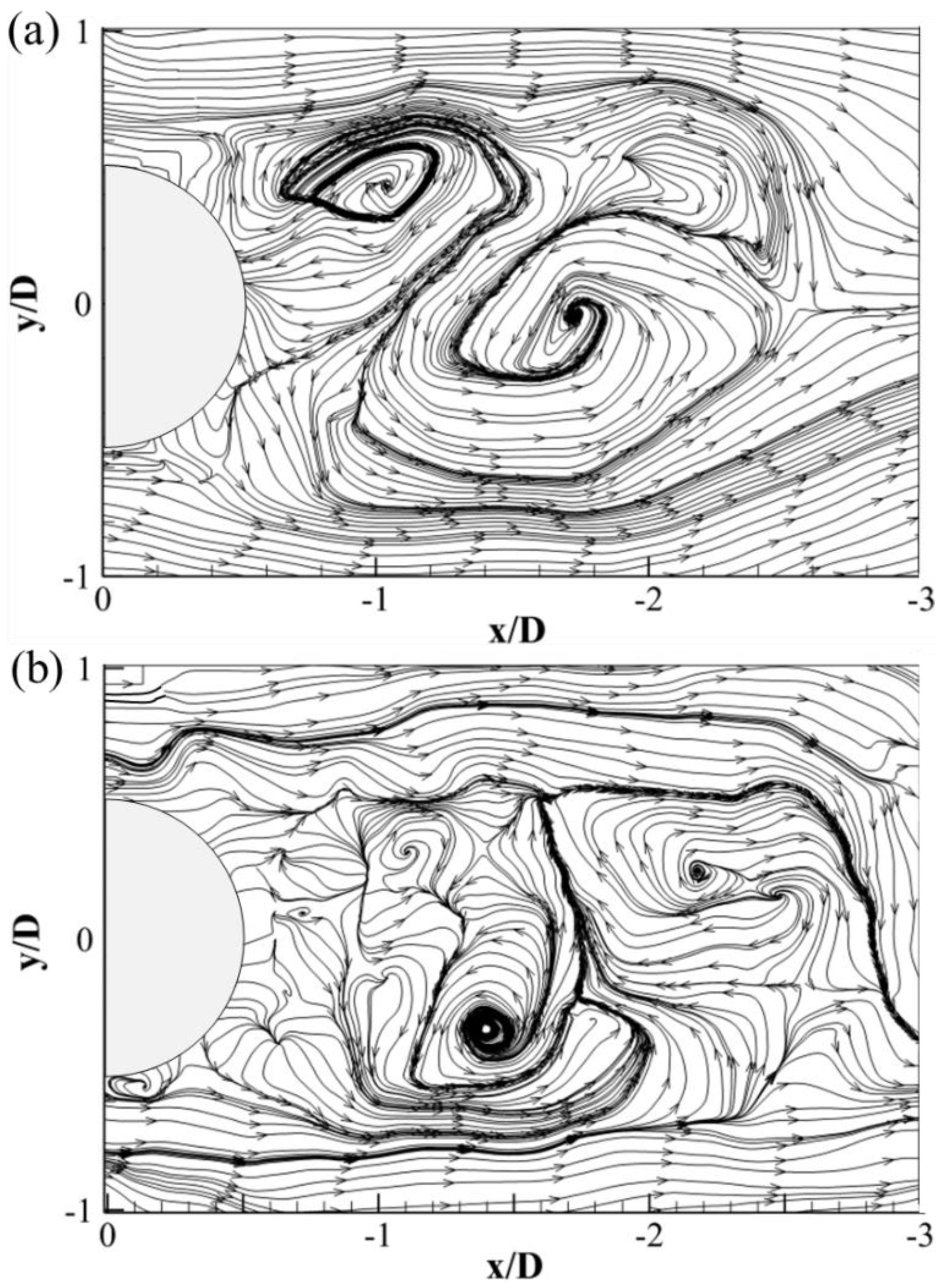
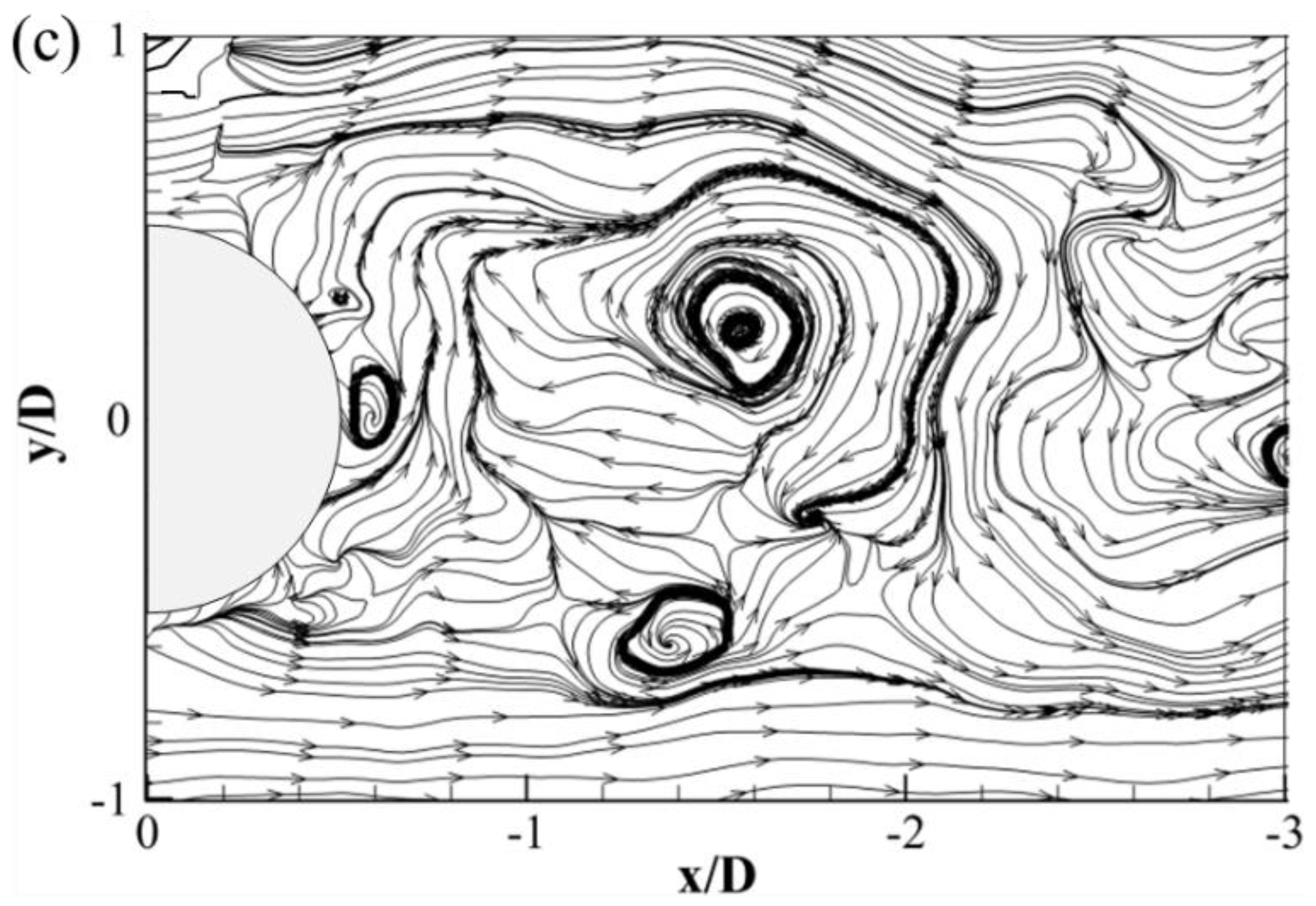
For the wake of the smooth cylinder, two large eddies and a foci point were observed (Figure 13a), in agreement with Wang and Zhou’s observation of mushroom ribs [44]. This phenomenon was attributed to the separating boundary layers on both sides of the cylinder model [45]. Comparison of the vortex shedding positions after the three cases revealed that the vortex shedding positions after the original grooved and the secondary grooved cylinders were advanced, and confirmed that the grooved cylinder reduced the recirculation region and suppressed the transitions in the boundary layer. Meanwhile, the focal point may have been formed by squeezing the large vortices. For the grooved cylinder models (Figure 13b,c), small vortices formed due to the backward shift of the boundary layer separation point, which was attributed to the groove structure. The number of vortices increased in the wake region of the secondary grooved cylinder due to a tip structure; the large-scale vortices broke up into more small-scale vortices. Hence, the spike structure is a vortex generator, and directly impacts the generation of small eddies.
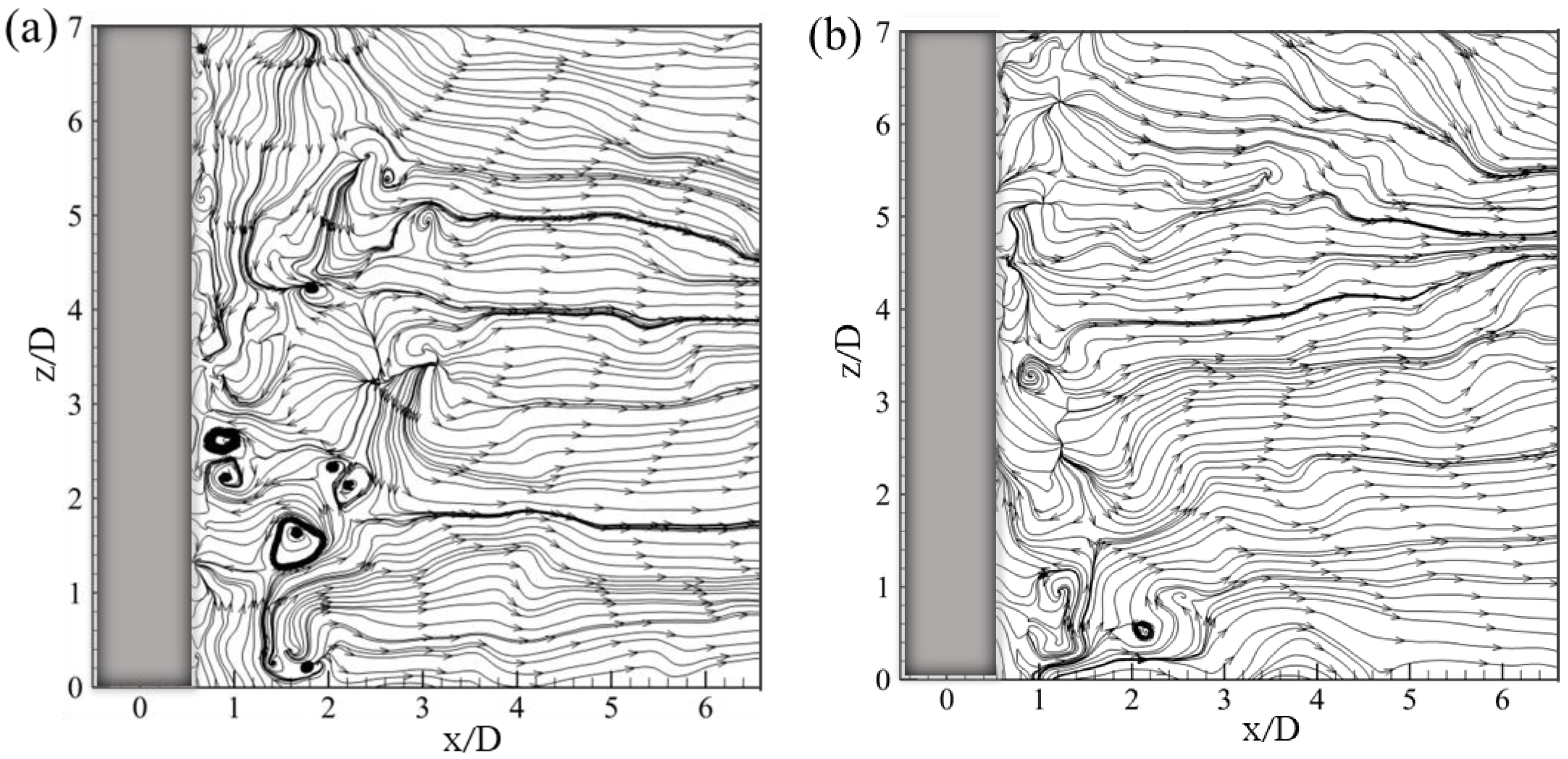
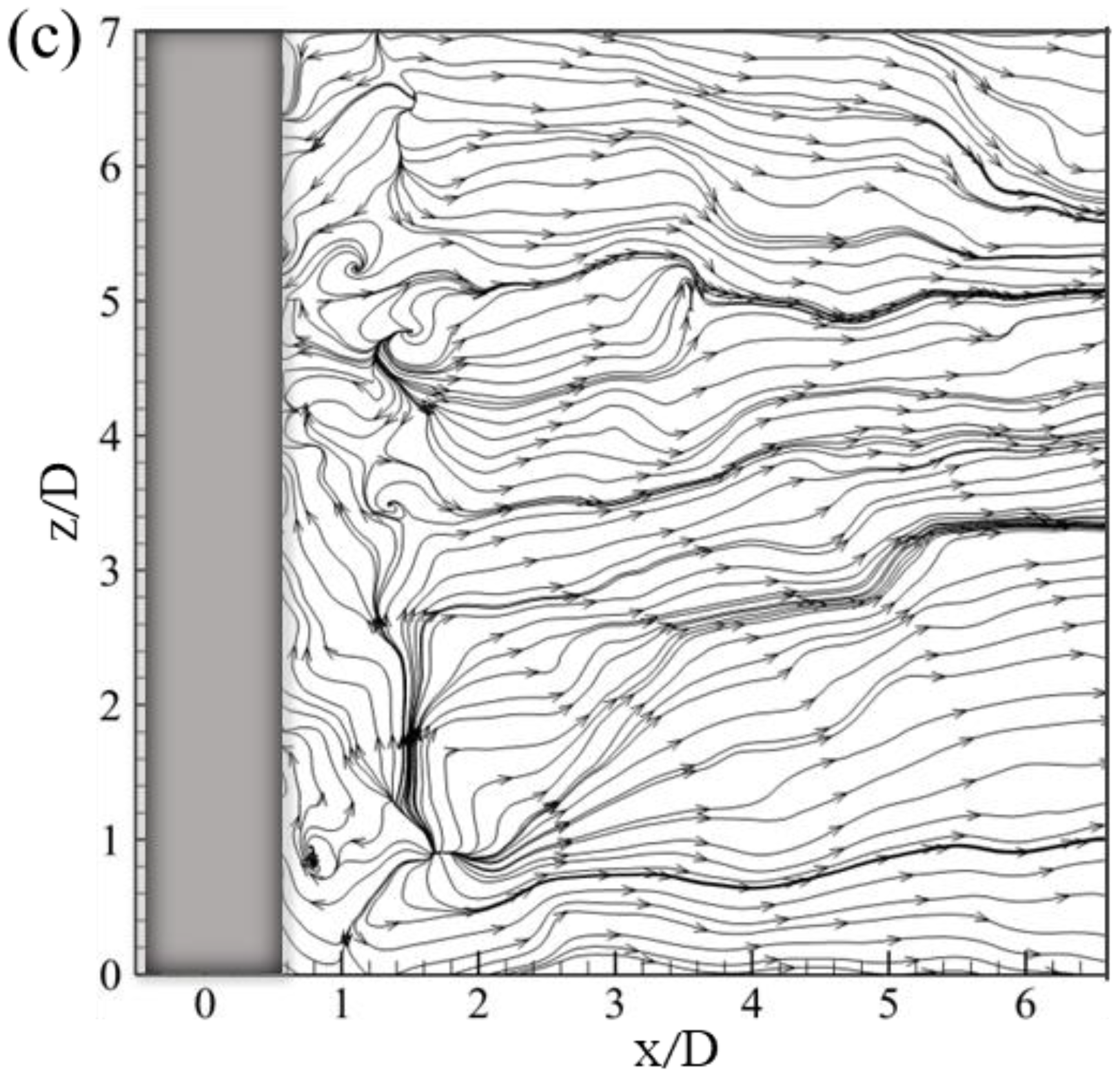
Figure 14 plots the typical instantaneous streamlines of the smooth cylinder and the grooved cylinders in the (x, z)-plane of y/D = 0. Several small spanwise vortices were found in the smooth cylinder wake region (Figure 14a); this may be because the wake was affected by the spanwise length of the cylinder. Another reason may be due to the rolling and sweeping effect of the spanwise transition layer in the near wake region [46]. However, small vortices were reduced in the spanwise wake region of the grooved cylinders (Figure 14b,c), which was different from the increase of vortices in the (x, y)-plane wake region. This may be attributed to the fact that the spanwise vortices of small sizes generated by the grooved cylinder follow the wake-to-do reversed flow movement and adheres to the inside of the grooves structure during the reversed flow movement, resulting in the reduced number of vortices in the wake region.

4. Conclusions

To investigate the influence of the spike of the secondary grooved structure on the wake features, a comparative study of the smooth, the grooved, and the secondary grooved cylinders was conducted in terms of the time-averaged streamlines, the time-averaged velocity, Reynolds shear stress, turbulent kinetic energy, the spectral characters, and instantaneous streamlines of the velocity. More detailed conclusions can be obtained as follows:
(1)
The wake structure downstream of the cylinder was improved by the groove structure, resulting in the reduction of the recirculation region, especially in the secondary groove structure. The flow-direction velocity gradient of the grooved cylinders was found to be less than that of a smooth cylinder;
(2)
The secondary grooved cylinder reduced the turbulent fluctuation within the boundary layer, resulting in the maximum Reynolds shear stress being suppressed. Moreover, compared to a smooth cylinder, the maximum of TKE was reduced by 42% for the secondary grooved cylinder, which indicates that the formation of secondary vortices was suppressed;
(3)
For spectral characters of the velocity component, both small-scale and large-scale vortices were present in the wake vortex shedding, while the secondary grooved cylinder reduced the power spectrum;
(4)
For the instantaneous flow structures, the spike structure was deemed to be a vortex generator, and directly impacts the generation of small eddies and the dissipation of large vortices.
This work shows the wake structure of the secondary grooved cylinder. In the future, there are two aspects of work that can be performed: one should to study the dynamics of the cylinder-wake/boundary-layer interaction; the other one would be to study the rotating cylinder with a different roughness.

Author Contributions

Conceptualization, L.L.; methodology, L.L.; validation, F.Y. and L.L.; formal analysis, L.L.; investigation, F.Y.; data curation, X.L.; writing—original draft preparation, L.L.; writing—review and editing, F.Y.; visualization, J.W.; Supervision, Z.S. All authors have read and agreed to the published version of the manuscript.

Funding

This research was funded by Natural Science Foundation of Jiangsu Province of China (No. BK20191459), and the National Natural Science Foundation of China (No. 12002138, 51705214).

Informed Consent Statement

Not applicable.

Data Availability Statement

No new data were created or analyzed in this study. Data sharing is not applicable to this article.

Acknowledgments

The author wishes to acknowledge the support given to him by the Natural Science Foundation of Jiangsu Province of China (No. BK20191459), and the National Natural Science Foundation of China (No. 12002138, 51705214).

Conflicts of Interest

The authors declare no conflict of interest.

References

  1. Rashidi, S.; Hayatdavoodi, M.; Esfahani, J.A. Vortex shedding suppression and wake control: A review. Ocean. Eng. 2016, 126, 57–80. [Google Scholar] [CrossRef]
  2. Zheng, Y.; Rinoshika, H.; Zhang, D.; Rinoshika, A. Analyses on flow structures behind a wavy square cylinder based on continuous wavelet transform and dynamic mode decomposition. Ocean. Eng. 2020, 216, 108117. [Google Scholar] [CrossRef]
  3. Gu, F.; Wang, J.S.; Qiao, X.Q.; Huang, Z. Pressure distribution, fluctuating forces and vortex shedding behavior of circular cylinder with rotatable splitter plates. J. Fluids Struct. 2012, 28, 263–278. [Google Scholar] [CrossRef]
  4. Assi, G.; Bearman, P.W.; Tognarelli, M.A. On the stability of a free-to-rotate short-tail fairing and a splitter plate as suppressors of vortex-induced vibration. Ocean Eng. 2014, 92, 234–244. [Google Scholar] [CrossRef]
  5. Seo, J.; Yun, J.; Lee, J. Control of Turbulent Flow over a Circular Cylinder Using Tabs. Mathematics 2023, 11, 968. [Google Scholar] [CrossRef]
  6. Xie, F.; Yu, Y.; Constantinides, Y.; Triantafyllou, M.S.; Karniadakis, G.E. U-shaped fairings suppress vortex-induced vibrations for cylinders in cross-flow. J. Fluid Mech. 2015, 782, 300–332. [Google Scholar] [CrossRef]
  7. Liu, K.; Deng, J.; Mei, M. Experimental study on the confined flow over a circular cylinder with a splitter plate. Flow Meas. Instrum. 2016, 51, 95–104. [Google Scholar] [CrossRef]
  8. Hwang, J.Y.; Yang, K.S. Drag reduction on a circular cylinder using dual detached splitter plates. J. Wind Eng. Ind. Aerodyn. 2007, 95, 551–564. [Google Scholar] [CrossRef]
  9. Sahu, Y. Flow-induced vibration of a circular cylinder with rigid splitter plate. J. Fluids Struct. 2019, 89, 244–256. [Google Scholar] [CrossRef]
  10. Zhou, B.; Wang, X.; Guo, W.; Gho, W.M.; Tan, S.K. Experimental study on flow past a circular cylinder with rough surface. Ocean Eng. 2015, 109, 7–13. [Google Scholar] [CrossRef]
  11. Afroz, F.; Sharif, M.A. Numerical study of cross-flow around a circular cylinder with differently shaped span-wise surface grooves at low Reynolds number. Eur. J. Mech. B/Fluids 2022, 91, 203–218. [Google Scholar] [CrossRef]
  12. Quintavalla, S.J.; Angilella, A.J.; Smits, A.J. Drag reduction on grooved cylinders in the critical Reynolds number regime. Exp. Therm. Fluid Sci. 2013, 48, 15–18. [Google Scholar] [CrossRef]
  13. Munendra, C.; Inamdar, A.; Kumar, R.; Science, G. Numerical studies of drag reduction on circular cylinder with V-grooves. Int. J. Eng. Res. 2015, 3. Available online: https://citeseerx.ist.psu.edu/document?repid=rep1&type=pdf&doi=e19955455326c2ef162cecb4b8752bce667eedae (accessed on 24 May 2023).
  14. Sun, C.; Zhou, T.; An, H.; Zhu, H.; Cheng, L.; Flow, F. Experimental studies on wake structures of a circular cylinder with different surface roughness heights. Int. J. Heat 2022, 94, 108941. [Google Scholar] [CrossRef]
  15. Aleksyuk, A. Analysis of three-dimensional transition mechanisms in the near wake behind a circular cylinder. Eur. J. Mech. B. Fluids 2018, 72, 456–466. [Google Scholar] [CrossRef]
  16. Xha, B.; Yt, C.; Zm, A.; Fei, F.A.; Aqb, D.; Jian, G.E.; Jw, B. Surface roughness effect on cylinder vortex-induced vibration at moderate Re regimes. Ocean Eng. 2021, 224, 108690. [Google Scholar] [CrossRef]
  17. Merzkirch, W. Particle Image Velocimetry. In Optical Measurements: Techniques and Applications; Mayinger, F., Feldmann, O., Eds.; Springer: Berlin/Heidelberg, Germany, 2001; pp. 341–357. [Google Scholar] [CrossRef]
  18. Huang., S. VIV suppression of a two-degree-of-freedom circular cylinder and drag reduction of a fixed circular cylinder by the use of helical grooves. J. Fluids Struct. 2011, 27, 1124–1133. [Google Scholar] [CrossRef]
  19. Canpolat, C. Characteristics of flow past a circular cylinder with a rectangular groove. Flow Meas. Instrum. 2015, 45, 233–246. [Google Scholar] [CrossRef]
  20. Levy, B.; Liu, Y. The effects of cactus inspired spines on the aerodynamics of a cylinder. J. Fluids Struct. 2013, 39, 335–346. [Google Scholar] [CrossRef]
  21. Talley, B.S.; Mungal, G. An Experimental and Computational Investigation of Flow Past Cacti; Annual Research Briefs; Center for Turbulence Research, NASA Ames/Stanford University: Silicon Valley, CA, USA, 2001; pp. 51–63. [Google Scholar]
  22. Qi, J.; Yue, Q.; Qunyan, C.; Fei, Y. A Study of Drag Reduction on Cylinders with Different V-Groove Depths on the Surface. Water 2021, 14, 36. [Google Scholar] [CrossRef]
  23. Jiang, S.; Yan, F.; Zhang, J.; Song, B. Multi-Scale Wake Characteristics of the Flow over a Cylinder with Different V-Groove Numbers. Water 2023, 15, 805. [Google Scholar] [CrossRef]
  24. Feng, B.; Wang, J.; Chen, D.; Liu, Z.; Jiang, S. Drag reduction mechanism of feather-like riblet film. J. Funct. Mater. 2016, 47, 1–4. [Google Scholar] [CrossRef]
  25. Reif, W.E. Morphogenesis and function of the squamation in sharks. Neues Jahrb. Geol. Paläontologie Abh. 1982, 164, 172–183. [Google Scholar] [CrossRef]
  26. Wachter, F.; Metelkin, A.; Jovanovi, J.; Pra, J.; Becker, S. Numerical investigation of the effect of convex transverse curvature and concave grooves on the turbulent boundary layer along a cylinder in axial flow. Int. J. Heat Fluid Flow 2021, 92, 108855. [Google Scholar] [CrossRef]
  27. Cheng, P.; Jiang, C.; Wu, C. Numerical simulation of drag reduction characteristics in bionic secondary micro-grooved surface. China Sci. 2014, 9, 940–943. [Google Scholar]
  28. Takayama, S.; Aoki, K. Numerical Analysis of Flow Characteristics around Circular Cylinders with Arc Grooves (SCHOOL OF ENGINEERING). Proc. Sch. Eng. Tokai Univ. 2005, 30, 1–5. [Google Scholar]
  29. Zhou, B.; Wang, X.; Guo, W.; Zheng, J.; Tan, S.K. Experimental measurements of the drag force and the near-wake flow patterns of a longitudinally grooved cylinder. J. Wind. Eng. Ind. Aerodyn. 2015, 145, 30–41. [Google Scholar] [CrossRef]
  30. Apelt, G. Measurements of Fluctuating Pressures and Forces on a Circular Cylinder in the Reynolds Number Range 104 to 2·5 × 105. J. Fluids Struct. 1993, 7, 227–244. [Google Scholar] [CrossRef]
  31. Oruç, V.; Akilli, H.; Sahin, B. PIV measurements on the passive control of flow past a circular cylinder. Exp. Therm. Fluid Sci. 2016, 70, 283–291. [Google Scholar] [CrossRef]
  32. Caliskan, M.; Tantekin, A.; Tumen Ozdil, N.F.; Akilli, H. Investigation of flow characteristics for triangular grooved shape cylinder at different heights in shallow water. Ocean Eng. 2021, 225, 108788. [Google Scholar] [CrossRef]
  33. Liu, Y.Z.; Shi, L.L.; Yu, J. TR-PIV measurement of the wake behind a grooved cylinder at low Reynolds number. J. Fluids Struct. 2011, 27, 394–407. [Google Scholar] [CrossRef]
  34. Zhu, H.; Zhou, T. Flow around a circular cylinder attached with a pair of fin-shaped strips. Ocean Eng. 2019, 190, 106484. [Google Scholar] [CrossRef]
  35. Fujisawa, N.; Hirabayashi, K.; Yamagata, T. Aerodynamic noise reduction of circular cylinder by longitudinal grooves. J. Wind. Eng. Ind. Aerodyn. 2020, 199, 104129. [Google Scholar] [CrossRef]
  36. Rinoshika, H.; Rinoshika, A. Passive control of a front inclined hole on flow structures around a surface-mounted short cylinder. Ocean Eng. 2019, 189, 106383. [Google Scholar] [CrossRef]
  37. Baek, H.; Karniadakis, G.E. Suppressing vortex-induced vibrations via passive means. J. Fluids Struct. 2009, 25, 848–866. [Google Scholar] [CrossRef]
  38. Aguedal, L.; Semmar, D.; Berrouk, A.S.; Azzi, A.; Oualli, H. 3D vortex structure investigation using Large Eddy Simulation of flow around a rotary oscillating circular cylinder. Eur. J. Mech. B/Fluids 2018, 71, 113–125. [Google Scholar] [CrossRef]
  39. Zheng, Y.; Rinoshika, A.; Fujimoto, S. Triangle Cylinder Wake Analysis Based on Wavelet and POD Techniques. Procedia Eng. 2015, 126, 108–112. [Google Scholar] [CrossRef]
  40. Foo, K.; Liang, Y.Y.; Tan, C.K.; Fimbres Weihs, G.A. Coupled effects of circular and elliptical feed spacers under forced-slip on viscous dissipation and mass transfer enhancement based on CFD. J. Membr. Sci. 2021, 637, 119599. [Google Scholar] [CrossRef]
  41. Lim, H.C.; Lee, S.J. PIV measurements of near wake behind a U-grooved cylinder. J. Fluids Struct. 2003, 18, 119–130. [Google Scholar] [CrossRef]
  42. Zheng, C.; Zhou, P.; Zhong, S.; Zhang, X.; Huang, X.; So, R.C.-H. An experimental investigation of drag and noise reduction from a circular cylinder using longitudinal grooves. Phys. Fluids 2021, 33, 115110. [Google Scholar] [CrossRef]
  43. Qi, J.; Shao, Y.; Chen, Q.; Liu, P.; Chen, C.; Wang, D.; Yang, H.; Yan, F. Dynamic Analysis of Wake Characteristics of the Circular Cylinder with a Dimpled Surface. Water 2021, 13, 2197. [Google Scholar] [CrossRef]
  44. Wang, H.F.; Zhou, Y. The finite-length square cylinder near wake. J. Fluid Mech. 2009, 638, 453–490. [Google Scholar] [CrossRef]
  45. Sakamoto, H.; Arie, M. Vortex shedding from a rectangular prism and a circular cylinder placed vertically in a turbulent boundary layer. J. Fluid Mech. 1983, 126, 147–165. [Google Scholar] [CrossRef]
  46. Zhou, T.; Razali, S.; Hao, Z.; Cheng, L. On the study of vortex-induced vibration of a cylinder with helical strakes. J. Fluids Struct. 2011, 27, 903–917. [Google Scholar] [CrossRef]
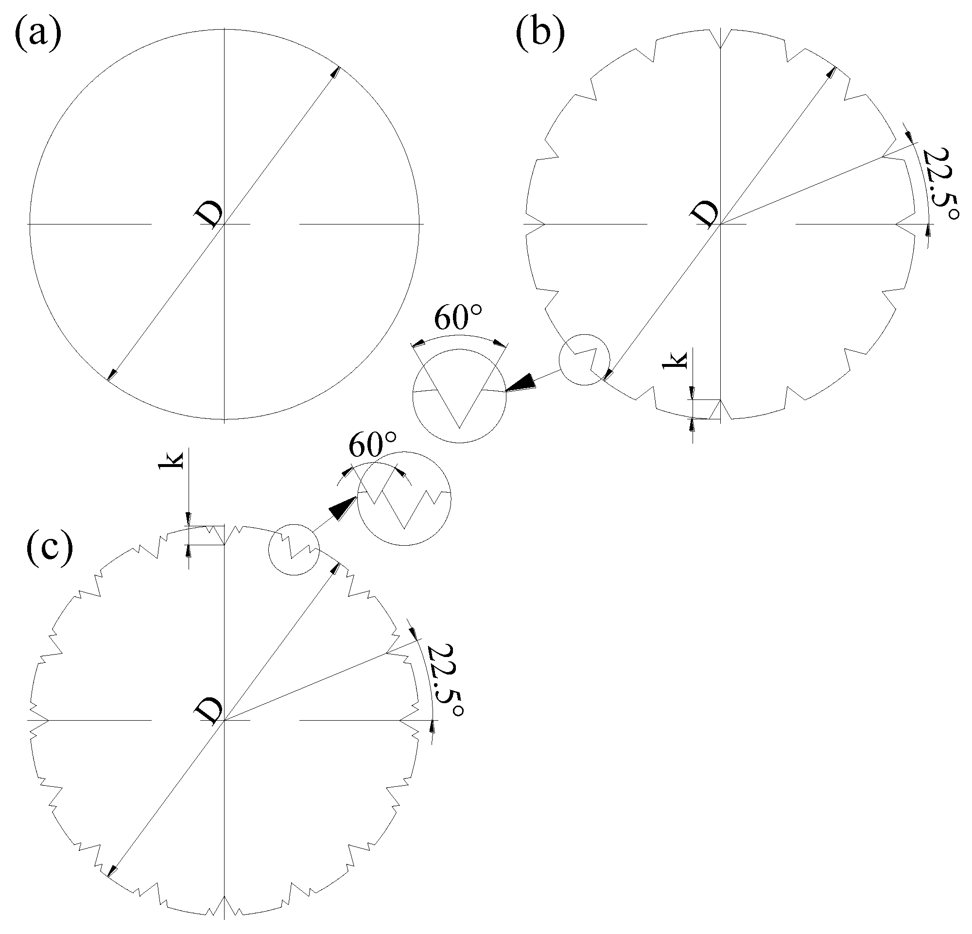
Figure 1. The sketch of the experimental models utilized in this study. (a) The smooth cylinder’s cross-section, (b) the original grooved cylinder’s cross-section, (c) the secondary grooved cylinder’s cross-section, (A) Top view of the smooth cylinder, (B) Top view of the original grooved cylinder, (C) Top view of the secondary grooved cylinder.
Water 15 02073 g001aWater 15 02073 g001b
Figure 2. PIV measurement planes and the measurement setup. (a) (x, y)−plane; (b) (x, z)-plane; and (c) the experimental setup and experimental model.
Water 15 02073 g002
Figure 3. The contours of the streamlines and the streamwise velocity   u ¯ / U in the (x, y)-plane in the (a) smooth cylinder, (b) original grooved cylinder, and (c) secondary grooved cylinder, respectively.
Water 15 02073 g003
Figure 4. Schematic diagram of the wake velocity extraction location.
Water 15 02073 g004
Figure 5. Profiles of time-averaged streamwise velocity in the (x, y)−plane.
Water 15 02073 g005aWater 15 02073 g005b
Figure 6. The distributions of the streamlines and streamwise velocity in the (x, z)-plane in the (a) smooth cylinder, (b) original grooved cylinder, and (c) secondary grooved cylinder, respectively.
Water 15 02073 g006
Figure 7. Profiles of the averaged streamwise velocity in the (x, z)-plane.
Water 15 02073 g007
Figure 8. Distributions of the normalized Reynolds shear stress in the (x, y)-plane at z/D = 0 in the (a) smooth cylinder, (b) original grooved cylinder, and (c) secondary grooved cylinder, respectively.
Water 15 02073 g008aWater 15 02073 g008b
Figure 9. Contours of the Reynolds shear stress u w ¯ / U 2 in the (x, z)-plane at y/D = 0 in the (a) smooth cylinder, (b) original grooved cylinder, and (c) secondary grooved cylinder, respectively.
Water 15 02073 g009aWater 15 02073 g009b
Figure 10. Contours of the normalized turbulent kinetic energy in the (x, y)-plane at z/D = 0 in the (a) smooth cylinder, (b) original grooved cylinder, and (c) secondary grooved cylinder, respectively.
Water 15 02073 g010aWater 15 02073 g010b
Figure 11. Contours of the turbulent kinetic energy in the (x, z)-plane at y/D = 0 in the (a) smooth cylinder, (b) original grooved cylinder, and (c) secondary grooved cylinder, respectively.
Water 15 02073 g011aWater 15 02073 g011b
Figure 12. Spectral characteristic (SV) of the velocity component v at x/D = −1.2, y/D = 0.6, and z = 0, respectively. (a) Smooth cylinder (b), original grooved cylinder, and (c) secondary grooved cylinder.
Water 15 02073 g012
Figure 13. Instantaneous streamlines in the (x, y)-plane at z/D = 0 in the (a) smooth cylinder, (b) original grooved cylinder, and (c) secondary grooved cylinder, respectively.
Water 15 02073 g013aWater 15 02073 g013b
Figure 14. Instantaneous streamlines in the (x, z)-plane of y = 0 in the (a) smooth cylinder, (b) original grooved cylinder, and (c) secondary grooved cylinder, respectively.
Water 15 02073 g014aWater 15 02073 g014b
Disclaimer/Publisher’s Note: The statements, opinions and data contained in all publications are solely those of the individual author(s) and contributor(s) and not of MDPI and/or the editor(s). MDPI and/or the editor(s) disclaim responsibility for any injury to people or property resulting from any ideas, methods, instructions or products referred to in the content.