Article

Design and Modeling of a Biotechnological Nanofiltration Module Using Bacterial Cellulose Membranes for the Separation of Oily Mixtures

by
Alexandre D’Lamare Maia de Medeiros
1,2,
Cláudio José Galdino da Silva Junior
1,2,
Júlia Didier Pedrosa de Amorim
1,2,
Italo José Batista Durval
2,
Ricardo Barbosa Damian
3,
Yasmim de Farias Cavalcanti
2,4,
Andréa Fernanda de Santana Costa
5 and
Leonie Asfora Sarubbo
2,4,*
1
Rede Nordeste de Biotecnologia (RENORBIO), Universidade Federal Rural de Pernambuco, Rua Dom Manuel de Medeiros, s/n-Dois Irmãos, Recife 52171-900, Brazil
2
Instituto Avançado de Tecnologia e Inovação (IATI), Rua Potyra, n. 31, Prado, Recife 50751-310, Brazil
3
CAEXPERTS, Parque Tecnológico Alfa, Edifício CELTA, sala 2.02, Rodovia José Carlos Daux, n. 600, Itacorubi, Florianópolis 88030-902, Brazil
4
Escola UNICAP Icam Tech, Universidade Católica de Pernambuco (UNICAP), Rua do Príncipe, n. 526, Boa Vista, Recife 50050-900, Brazil
5
Centro de Design Comunicação, Centro Acadêmico da Região Agreste, Universidade Federal de Pernambuco (UFPE), Av Marielle Franco, s/n-Nova Caruaru, Caruaru 50670-900, Brazil
*
Author to whom correspondence should be addressed.
Water 2023, 15(11), 2025; https://doi.org/10.3390/w15112025
Submission received: 12 April 2023 / Revised: 16 May 2023 / Accepted: 21 May 2023 / Published: 26 May 2023
(This article belongs to the Special Issue Nanomaterials Application in the Treatment of Wastewater)

Abstract

:
The environmental impacts of the exploration and use of petroleum and derivatives in recent decades have led to increasing interest in novel materials and processes for the treatment of oily effluents. Oily emulsions are difficult to manage and, in some cases, require different types of treatment or combined methods for phase separation. Sustainable, versatile, innovative biomaterials, such as bacterial cellulose (BC), have considerable applicability potential in mixture separation methods. In the present study, a cellulose membrane produced by a symbiotic culture of bacteria and yeasts (SCOBY) was investigated with the aim of measuring the characteristics that would enable its use in the treatment of oily wastewater. BC was analyzed through physicochemical characterizations, which demonstrated its porosity (>75%), chemical structure with high cellulose content and a large quantity of intramolecular H bonds, good thermal stability with maximum degradation at temperatures close to 300 °C, high crystallinity (66%), nanofibrils of approximately 84 nm in diameter and mechanical properties that demonstrated tensile strength of up to 65.53 Mpa, stretching of approximately 18.91% and the capacity to support a compression load of around 5 kN with only the loss of free water in its structure. The characteristic data of the membranes were used for the production of a filtering module for oily mixture separation processes. This support was developed with computational fluid dynamics of finite volumes and finite element structural analysis using advanced computer-assisted engineering tools. Lastly, the conceptual, basic project of a low-cost nanofiltration module was obtained; this module could be expanded to the industrial scale, operating with several modules in parallel.

1. Introduction

The environmental impact of pollution from the oil industry at the end of the 20th century and the beginning of the 21st century has caused numerous problems for society due to the high toxicity of gaseous, solid and liquid effluents, which reduce the quality of life of living beings. The oil industry is responsible for the largest part of the pollution of freshwater sources and groundwater, causing an imbalance in terrestrial and aquatic ecosystems and contaminating the atmosphere through the generation of electrical power via the burning of fuels [1,2,3].
Oily waste comes from diverse industrial sources and is produced in different processing steps. Environmental accidents, such as oil spills during the transport of petroleum, are common, generating the need for companies in the oil industry to treat oily effluents following the oil concentration parameters for the discard of effluents established by legislation in each country [4,5,6,7].
The oil in effluents is found in different forms with different degrees of difficulty in removal by one or several mixture separation methods [7]. In particular, emulsions (water in oil or oil in water) are quite complex and resistant to decomposition, as such substances involve not only oil, but also additional agents, such as anti-foaming agents and emulsifiers. The chemical stability of an emulsion makes its separation only possible through chemical and/or physical processes, generating a high treatment cost for companies [4,8,9].
According to Medeiros et al. (2022) [7], diverse methods can be used for the treatment of oily effluents depending on the type and quantity of oil in the mixture, its composition and the requirements of legislation. However, many of these treatments have low efficiency when used for mixtures that contain oily molecules of different sizes, causing diverse operational problems, the most common of which are the loss of volume of storage sites and the clogging of pipes [5,10].
Industries that use treated water from oily effluents for other processes need to pay more attention with regard to water parameters and the quantity of oil. Oil in sensitive equipment can cause irreparable damage, in some cases requiring the complete replacement of the equipment, and can exert a negative impact on heat exchange processes, as it alters the freezing point of water [9,11].
Studies on the treatment of effluents have been based on these deficiencies in the methods used by the industry for the complete removal of these pollutants, seeking the optimization of the processes and/or the use of novel materials and sustainable methods. These scientific advances have enabled the employment of biotechnological materials for the agglutination of oily molecules or as filtering membranes [5,6,12,13].
Bacterial cellulose (BC) is described in the literature as a biomaterial with vast functionality that can be used in these treatments. BC is produced through fermentation by different types of microorganisms, particularly bacteria of the genera Sarcina, Komagataeibacter and Agrobacterium [14,15]. BC biomembranes and biofilms have been applied in diverse industries, providing higher performance and replacing commonly used synthetic materials [16,17,18]. The high porosity and reticular structure with pores of small diameter (less than 100 nm) make biomembranes ideal for filtration of better quality. However, few studies and patents have been published in the literature addressing this line of research [5,6,12,19,20].
Bacterial cellulose membranes can offer several advantages over traditional methodologies for the filtration of oily effluents. They are highly hydrophilic and oleophobic, which means they retain oil and let the water pass through the membrane easily, resulting in a high separation efficiency. In terms of methodology, bacterial cellulose membranes can be produced in a variety of shapes and sizes, including flat sheets, tubes and fibers, enabling more flexibility in the filtration system design. Additionally, the modification of bacterial cellulose membranes can be tailored to specific filtration applications, allowing the customization of the membrane properties. These have shown promising results for oily effluent filtration due to their high efficiency, selectivity and sustainability over traditional methods [5,7,12].
Furthermore, in addition to bacterial cellulose membranes, which have shown promise in this context, recent and constantly evolving research has been dedicated to the development of nanoporous filtering membranes based on green and biodegradable resources. These innovations have shown a remarkable rate of contaminant removal, exceeding 95% [21,22,23,24]. These membranes, constructed from sustainably sourced materials, offer an eco-friendly approach to wastewater treatment, meeting efficiency demands and achieving environmental preservation. The continuous progress in this area promises to further boost the application of these solutions in the treatment of oily effluents, bringing benefits both to the industry and to the health of the ecosystem.
Therefore, the aim of the present study was to evaluate the physicochemical and mechanical characteristics of BC to demonstrate its capacity to remove oily compounds from industrial effluents. A further aim was to develop a conceptual, basic project for a prototype of a nanofiltration module using this biomaterial as a filtering membrane, evaluating diverse options of constructive forms, materials, dimensions and operational parameters to minimize the cost ratio per operating flow within acceptable pressure limits for bacterial cellulose. Computational fluid dynamics of finite volumes (CFD) and finite element structural analysis (FEA) using advanced computer-assisted engineering (CAE) tools were employed in a way that would enable possible expansion to the industrial scale by operating with several modules in parallel.

2. Materials and Methods

2.1. Production and Characterization of Bacterial Cellulose Membranes

2.1.1. Microorganisms and Maintenance Medium

Microorganisms from a symbiotic culture of bacteria and yeasts (SCOBY) obtained from the culture collection of the Center for Resources in Environmental Sciences of the Catholic University of Pernambuco, Brazil, were used for the production of BC. The maintenance and production medium, denominated green tea medium (GTM), was composed of 50 g/L of refined sugar (brand: Olho D’água, Brazil) and 10 g/L of green tea leaves (Camellia sinensis) (brand: Chá Leão, Brazil) and adjusted to pH 6 [25].

2.1.2. Culture Conditions and Purification

BC production was performed by transferring 10% (v/v) of a pre-inoculum containing the consortium of microorganisms to 1000 mL Schott flasks containing 500 mL of GTM. Static cultivation was performed at 30 °C for 14 days. Cleaning of the membranes was performed by rinsing in running water, followed by purification in a NaOH 0.1 M solution for one hour to eliminate retained cells and ensure a uniform color. The membranes were then neutralized to pH 7.0 [25].

2.1.3. Production Yield of Bacterial Cellulose and Water Retention Capacity

The moisture content of a biomaterial is directly linked to its water retention capacity (WRC). Absorption capacity and water permeability capacity are measured from this test. The BC membranes were weighed and dried in an oven for the complete removal of water until a constant weight was reached. The BC yield was then obtained, and the WRC was calculated using Equation (1):
W R C % = M e a n   o f   w e t   w e i g h t     M e a n   o f   d r y   w e i g h t M e a n   o f   w e t   w e i g h t

2.1.4. Characterization of Membranes

Determination of Water Contact Angle and Sorption Index

For this analysis, the BC membranes were prepared with a rectangular shape (10 mm × 5 mm). The water contact angle was determined by analyzing the interaction of the membrane in contact with water. For this, each sample was positioned on a flat surface. A goniometer and mirrorless digital camera (XT10, Fujifilm, Japan) were employed for the analysis, using the sessile drop technique, by which a droplet is carefully deposited on the surface of the membrane and the contact angle is measured after one second of spreading [26]. To determine the sorption index (s), the droplet was observed for 10 min until complete water absorption, and the average time was calculated [27].

Swelling Ratio

In this test, the BC membranes had the same shape and dimensions as in the previous test (10 mm × 5 mm), and the water was removed in a laboratory oven at 50 °C until reaching a constant weight. The samples were then weighed and immersed in distilled water maintained at 25 °C for 24 h. The samples were then removed and weighed following the removal of excess surface water. Swelling ratios were determined from the change in weight before and after swelling, as expressed in Equation (2):
S R   %   =   S w o l l e n   w e i g h t     I n i t i a l   w e i g h t I n i t i a l   w e i g h t × 100

Fourier Transform Infrared (FTIR) Spectroscopy

This technique is based on the vibrations of atoms in a molecule when the sample is subjected to electromagnetic radiation in the infrared range. The radiation absorbed by a molecule is converted into vibration energy recorded by a spectrometer in the form of absorption bands and used to furnish evidence of the presence of functional groups in the organic structure [28]. The result is a graph, commonly called an interferogram, with axes representing the response of the detector and the difference in the optical path [29].
For the tests, the BC membranes dried in an oven were kept in a desiccator with silica gel at a temperature of 25 ± 3 °C. Scanning of the sample was performed in a Bruker FTIR spectrometer (Alpha II, Bruker Co., Ettlingen, Germany) coupled to an attenuated total horizontal reflectance device through a crystal cell plate (45° ZnSe; 80 mm × 10 mm; thickness: 4 mm) (PIKE Technology Inc., Madison, WI, USA). Functional groups in the samples were identified after 32 scans with a resolution of 4 cm−1 in a scanning range between 4000 cm−1 and 400 cm−1.

Thermogravimetry

Thermogravimetric analysis (TGA) for the determination of the thermal stability of the samples was performed using a simultaneous thermal analyzer (Shimadzu, Kyoto, Japan, TGA-50 thermogravimetric module) with a platinum support (mass: 10,882 mg) for the membrane. The reading was performed in a temperature range of 25 to 800 °C, with a heating rate of 10 °C.min−1 and using nitrogen gas at a flow rate of 50 mL.min−1.
The TGA results were presented in mass variation curves per temperature. From this information, it is possible to determine the composition of the sample, the thermal stability and the quantification of inorganic residues [30].

X-ray Diffractometry

The X-ray diffraction (XRD) patterns of the samples were analyzed using a diffractometer (Bruker D8 Advance Eco, Billerica, MA, USA) with a copper tube and Kα1 radiation. The operating conditions of the equipment were 40 KV × 40 mA, resulting in 1600 W. The samples were read at a wavelength of 1.54050 Å and scanned at a rate of 3°.min−1 in the scanning range of 3° to 90°.

Scanning Electron Microopy and Energy-Dispersive Spectroscopy

The dried BC membrane was mounted on a copper stub using double-side carbon conducting adhesive tape and sputter coated with gold for 30 s (SC-701 Quick Coater, Tokyo, Japan). The qualitative identification of the elements in the sample was performed using an energy-dispersive spectroscopy (EDS) detector coupled to a scanning electron microscope (FEI INSPECT S50, Midland, ON, Canada). EDS analysis assists in the characterization of the elements in the sample and not the compounds, with a viable detection limit of 0.1% of concentration in mass.

Porosity

For the test, the surface water was removed from the samples, the dimensions and mass were measured and the samples were dried in a forced-air oven (Solid Steel, model SSDc 30 L) for 24 h at 50 °C. After drying, the dimensions and mass were measured a second time. The surface porosity of the membranes was determined using Equation (3), in which Ww and Wd are the mass of the wet and dried membranes (g), respectively; d is the density of water (1 g.cm−3); D is membrane thickness (cm); and A is the area of the membrane (cm2):
Porosity   =   Ww     Wd d × D × A   × 100   %

Mechanical Tests

Wet BC membranes used as the test specimens for these tests were prepared with dimensions of 22.37 ± 1.00 mm in width and 2.17 ± 0.19 mm in thickness. The tests were conducted at a constant temperature of 23.8 °C, relative air humidity of 46% and a velocity of 1 mm.min−1, using a 500 N load cell and 50 mm distance between sample fixation supports. A universal testing machine (Instron EMIC, model 23–30) was used following the ASTM D882 method for tensile properties of thin plastic sheets, and the tests were conducted in quintuplicate [31].

Compression

Wet BC membranes used as test specimens for these assays had dimensions of 74.02 ± 2.72 mm in diameter and 9.49 ± 2.50 mm in height. The tests were conducted at a constant temperature of 24.6 °C and 48% air humidity at a velocity of 1 mm.min−1 using a 5 kN load cell. A universal testing machine (Instron EMIC, model 23–30) was used, and the tests were performed in quintuplicate.

2.2. Modeling and Simulation of Filtering Module

2.2.1. Conceptual Project

In this stage, the constructive form, geometric proportions and main materials were defined based on research and creativity. The basic project focused on optimizing the cost, calculating the main dimensions, determining the operating parameters and generating the information necessary for the fabrication of the physical prototype [32].

2.2.2. Study of Constructive Forms

After research on possible configurations of filtering elements, the filtering model used in reverse osmosis was selected and adapted for our purposes. This consists of a cylindrical tube internally containing a spiral-wound multilayer filtering envelope, with the entrance of the effluent flow in the longitudinal direction of the cylinder, directing the filtered water in a radial-tangential-spiral way towards the center of the cylinder to an inner collector tube and pouring the self-wash waste into the other end of the cylinder [33,34].
This multilayer filtering blanket is made up of a bacterial cellulose membrane, metallic support screens and waterproofing plastic films. These elements are spirally wound around the inner perforated collecting tube (similar to a flute). The spiral assembly is press-fitted into the cylindrical vessel of the filter module by elastomeric sealing rings at the ends.
This configuration enables working with large filtering areas in a reduced cylindrical space, avoiding the high cost of pressure vessels, which increases considerably with the increase in diameter. Another advantage is the ability to be self-cleaning, which increases the lifetime of the filtering element and reduces operating costs [35].

2.2.3. Optimization Process

Optimization was used to guide the basic sizing of the set and selection of materials to minimize the manufacturing cost ratio per operating flow, respecting some pertinent limitations.
Based on laboratory tests and literature research on this type of filter element configuration [5], an operating pressure-drop restriction was created. The fluid passage through the bacterial cellulose membrane was limited to 3.0 bar, and the fluid passage longitudinally along the spiral envelope was limited to 0.3 bar (structural stability and sealing of the spiral envelope in the cylindrical tube).
Calculations of flow and pressure drop as well as calculations of the structural strength of the vessel were performed in a simplified way in this step. The simplified calculation and cost estimation process used within the optimization loop is described [36].
The optimized variables were the constructive dimensions and their derivations, such as the surface area of filtration, diameter of the external tube (pressure vessel), diameter of the internal collecting tube (flute), diameter of the inlet (effluent) and outlet connections (filtered and disposal), module length, number of spiral windings, envelope thicknesses and materials (filtering membrane, support screens, waterproofing film), structural materials (pipes, flanges and connections) and seals. The Microsoft Excel optimization solver was used with the evolutionary genetic algorithm, as several discrete variables were used.

2.2.4. Material Selection

For the selection of materials, it was necessary to consider sanitary issues (non-contamination of nanofiltered water), corrosion (saline environment, seawater), prototype-oriented fabrication processes (small number of parts) and ease of finding raw materials on the market (plates, tubes, screws, seals, connections, etc.).
The structural materials selected were all stainless steel, with commercial pipes in “schedule” gauge with flanges at the ends made of laser-cut plates fixed with stainless-steel screws and using threaded connections welded to the stainless-steel flanges. The sealing ring at the ends of the spiral envelope was made of polyurethane rubber [37].
The envelope was made up of a bacterial cellulose membrane, support screens of two sizes (mesh opening and wire thickness) in stainless steel, waterproofing plastic film in polypropylene and a non-toxic epoxy glue for sealing the ends of the layers and the spiral envelope.

2.2.5. Basic Dimensional Calculations

The simplified pressure-drop calculations used in the optimization loop were based on equations of analytical fluid dynamics, with some adaptations. In the filtering membrane, a coefficient of linear pressure drop with velocity (Darcy’s equation) determined from the experiments was used. In the flow between layers (filtering and waterproofing) along the support and spacing screens, a combination of internal flow between flat plates and external flow around cylinders was used, both in turbulent regime, with the pressure drop proportional to the square of the velocity. In the connections and inner tube of the collector, pipeline network flow equations were used, with localized loss coefficients (contractions, expansions, passage through holes, changes in direction) [38].
Wall thickness calculations of the structural components involved the basic equation of thin-walled cylindrical pressure vessels, by which wall thickness varies quadratically with tube diameter.

2.2.6. Adaptation of Optimized Solution

After the optimization process, it was necessary to adapt the optimized solution to the sizes, materials and gauges available on the market. For example, the outer tube selected was 3” in schedule 5 gauge. The inner tube was 3/8” schedule 10, with holes 3 mm in diameter. Flange plates were 1/8” in thickness with 1/4” hex bolts for strength class 8.8. The threaded input connection was 1/2” gauge, and the output threads were 3/8”.

2.2.7. Refining the Final Solution (CFD, FEA, Setup, Adjustments)

Once the solution was optimized and adapted, a detailed verification process was performed to refine the sizing with the aid of advanced three-dimensional engineering simulation (CAE) tools for fluid dynamic (CFD) and structural (FEA) calculations.
The CFD study involved the ANSYS CFX solver (element-based finite volume method) with a hexahedral structured mesh in the envelope region and tetrahedral unstructured mesh in the input and output region and collector tube. A linear loss coefficient was used for head loss in the filtering element, and a quadratic loss coefficient was used for head loss in the channel of the screens. As a boundary condition, the inlet and outlet flows were prescribed, and head losses were measured in each stage [39].
The ANSYS Mechanical software (finite element method) was used for the structural simulation, with contact nonlinearity (flange connections), geometric nonlinearity (large deflections) and tetrahedral unstructured mesh, considering the application of the maximum internal operating pressure (more conservative case). Maximum von Mises stresses and contact pressure on the flanges were determined.

2.2.8. Summary of Final Configuration (Fabrication)

This step of the design of the filtering module was based on all characteristics acquired throughout the fluid dynamics studies for the construction and fabrication of the first membrane support prototype using the materials considered optimal for the filtering process.

2.2.9. Adaptation of Physical Space and Assembly of Subsystems

The biotechnological membrane and its support are extremely important for the filtration process to occur with the greatest possible efficiency but do not function without operational subsystems. For the fluid to exert the necessary pressure in the internal portion of the filtering module, a peristaltic pump was used with a recirculation system, pressure regulator and gauges so that constant pressure could be maintained. Moreover, fixed and movable structural platforms (Figure 1) were developed, fabricated and installed for the support of the effluent tanks (to be treated, filtered and residual) and as support for the filter itself, pump and other materials.

2.2.10. Production of Cellulose Membranes following Model Proposed in Computational Simulation

BC production was performed by transferring 10% (v/v) of a pre-inoculum containing the consortium of microorganisms to 5000 mL Schott flasks containing 2500 mL of the green tea medium. Static cultivation was performed at 30 °C for 14 days. This cultivation served as a pre-inoculum for the large-scale production of cellulose membranes in a glass recipient measuring 0.90 × 0.50 × 0.15 m (Figure 2) containing 20 to 30 L of green tea medium.
The BC was rinsed in running water, and purification was achieved by immersion in a 0.1 M NaOH solution at 90 °C for 1 h. The BC films were then neutralized and weighed, followed by the calculation of the yield.

3. Results and Discussion (Bacterial Cellulose Membrane)

3.1. Bacterial Cellulose Yield and Water Retention Capacity (WRC)

WRC was measured after the complete removal of the moisture from the BC membranes in a lab oven at 50 °C until reaching a constant weight (Figure 3). The results demonstrated a high percentage of water (>97%), as described by Silva Junior et al. (2022) [25], confirming that this quantity of water confers hydrophilic and oleophobic characteristics to the membrane.
After 14 days of production, the mean yield of the BC membranes (Figure 4) was 436.12 ± 17.03 g.L−1 of fermentation medium, and the mean yield of dry membranes was 10.24 ± 1.49 g.L−1. Such a yield is quite satisfactory compared to other production studies, such as 6.18 g.L−1 reported by Ul-Islam et al. (2020) [40] and 10.07 g.L−1 reported by Silva Junior et al. (2022) [25] after 14 days of production.
The results (Table 1) confirm that the BC membranes had high WRC (%), as described by Costa et al. (2017) [41] and Silva Junior et al. (2022) [25], reaching more than 97%. This is one of the most important properties for the efficient retention of oily molecules in the treatment of effluents, as a high concentration of water molecules in the nanofibrillar network increases its hydrophilicity.

3.2. Water Contact Angle, Swelling Ratio, Sorption Index and Porosity

The water contact angle obtained (36.56 ± 2.3°) is described in the literature as hydrophilic [5], as it offers greater contact of the droplet with its surface, which is a fundamental characteristic for the efficient separation of oily mixtures. The wettability of a BC membrane is extremely important for its filtration capacity, as it exerts an influence on the movement mechanism of the fluid, retaining oily molecules and permitting the passage of water [42]. This characteristic was determined by the time required for the membrane to absorb a drop of water (12.32 ± 2.12 s), which indicates the high water absorption capacity of the surface of the material.
The swelling capacity of membranes is dependent on the type and quantity of water retention agents and rehydration capacity. This factor is crucial for enabling the control of the properties of the membrane after extensive use, storage for long periods or accidental dehydration [27]. The results of the tests of the BC membranes were 61.93 ± 3.12%, indicating a high rehydration rate (greater than 50%), demonstrating the capacity of the membranes to reabsorb water even after complete drying.
The porosity index was 77.87 ± 3.25%, which is in agreement with rates described in the literature by Nascimento et al. 2022 [43] (76% to 91%) and Tang et al. 2010 [44] (65% to 92%). This high porosity, together with the other properties, explains the capacity of the BC membranes for use as filtering membranes for the treatment of contaminated effluents.

3.3. Fourier Transform Infrared (FTIR) Spectroscopy

The FTIR spectrum was used to analyze the chemical structure of the bacterial cellulose. The ATR-FTIR transmittance spectra of the sample in the region of 4000 to 400 cm−1 are shown in Figure 5. All spectra of the BC membrane show the presence of the characteristic bands of cellulose. The FTIR spectra of bacterial cellulose (Figure 5) showed distinguished cellulosic peaks at 3337 cm−1, 2893 cm−1, 1636 and 1314 cm−1, 1427 cm−1 and 1032 cm−1, which correspond to O-H stretching, C-H stretching of alkane and asymmetric stretching of CH2, CH angular deformation and CH2 deformation and C-O symmetric stretching of primary alcohol, respectively. All absorption bands of the characteristic chemical groups present in the sample are shown in Table 2. Inter- and intramolecular hydrogen (H) bonds in cellulose play an important role in the physical properties of cellulose [45,46,47,48,49]. The peak at 3337 cm−1 demonstrates a greater amount of intramolecular H bonds.
The information in Figure 5 and Table 2 shows absorption bands related to the methylene (CH2), hydroxyl (OH) and other oxygenated groups. These are the main attributes that characterize a pure bacterial cellulose, demonstrating that the membranes produced in the green tea medium in the present study are composed of pure BC. These chemical groups are produced during biosynthesis and are responsible for the high WRC encountered (97.65 ± 0.36%) as well as the water contact angle (36.56 ± 2.3°), which indicates the hydrophilic nature of the filtering membranes.

3.4. Thermogravimetry

The thermal stability of the BC membrane was investigated through the thermogravimetric analysis (TGA) of the samples obtained after 14 days. The results are displayed in Figure 6 and Table 3.
There are several other materials that have similar thermal resistance to bacterial cellulose, including some types of synthetic polymers such as polycarbonate (PC) [50] and natural materials such as cotton [51] and silk [52], which also exhibit good thermal resistance. However, each of these materials has its own unique set of properties and characteristics, which may make them more or less suitable for a given application compared to bacterial cellulose.
Three main stages of mass loss were found in the sample. The first degradation stage occurred between 23 and 245 °C, with an average loss of 5.72% of mass related to residual moisture in the sample. The second stage occurred at around 245 to 400 °C, when the greatest loss of mass occurred (average of 52.10%). This loss is related to the degradation of the cellulose, with its decomposition of glucose units and consequent de-polymerization, as the main stage of the pyrolysis of cellulose occurs in a temperature range of 300 to 380 °C [25,53]. The peak DTG also occurred in this stage, which shows a maximum rate of weight loss around 300 °C. This is in agreement with data reported in the literature [54,55]. The third stage occurred between 400 and 800 °C, with an average loss of 14.80%. In this stage, pyrolysis of polymer had already taken place, and the loss of mass was related to the degradation of residual carbon molecules. These observations indicate that the membranes have good thermal stability and can be applied in fields in which this property is important [56].

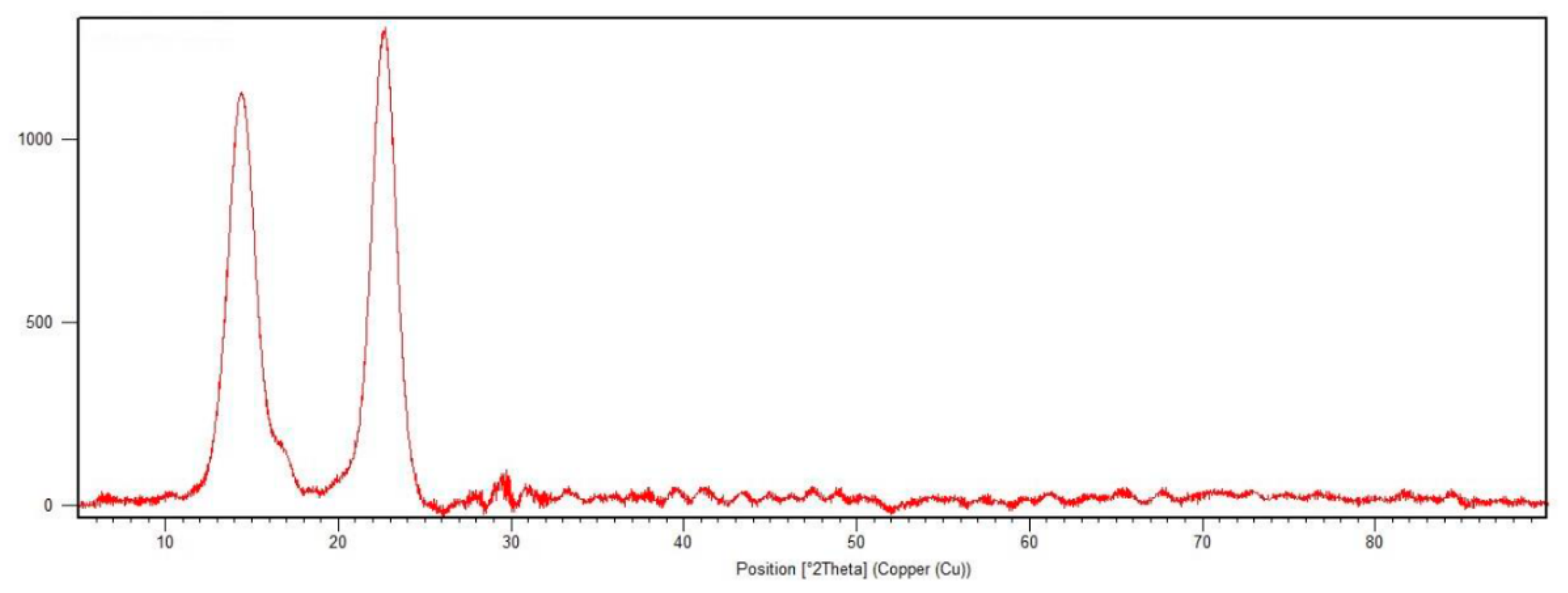
3.5. X-ray Diffractometry

The X-ray diffraction (XRD) analysis of the BC produced by SCOBY in GTM suggested its crystalline nature (Figure 7). The diffractogram shows three main visible peaks attributed to crystallographic planes 1–10, 110 and 200, corresponding to diffraction angles of 14.2°, 16.8° and 22.3°, respectively. These diffraction peaks are characteristic of type I cellulose, close to 2θ = 15° (triclinic structure (Iα) = 110 and monoclinic structure (Iβ) = 100), 17° (Iα = 010 and Iβ = 110) and 22.6° (Iα = 110 and Iβ = 200) [57].
The XRD pattern of the BC was very similar to that reported by Avcioglu et al. (2021) [58], who found peaks at diffraction angles of 14.4°, 16.88° and 22.72° for BC produced by a kombucha consortium in green tea medium for 10 days. The membrane had a crystallinity index of 77.99%, whereas the crystallinity of the membranes in the present study was 66%. Li et al. (2019) [59] studied the crystallinity of BC membranes produced by K. hansenii isolated from kombucha tea and found that the strain, culture conditions (static or stirred) and time affect the crystallinity index, which explains the difference between the studies. Most plant celluloses rich in Iβ have crystallinity between 40 and 60%, whereas the crystallinity of BC rich in Iα can reach up to 89% [59].
The crystallinity of cellulose is one of the important characteristics for several industries, as it is related to the mechanical properties [40]. The wettability rate depends on the density of the fibers and rigidity, as this property is related to the crystallinity of the fibers [60]. Crystallinity and the wettability rate are inversely proportional [61].

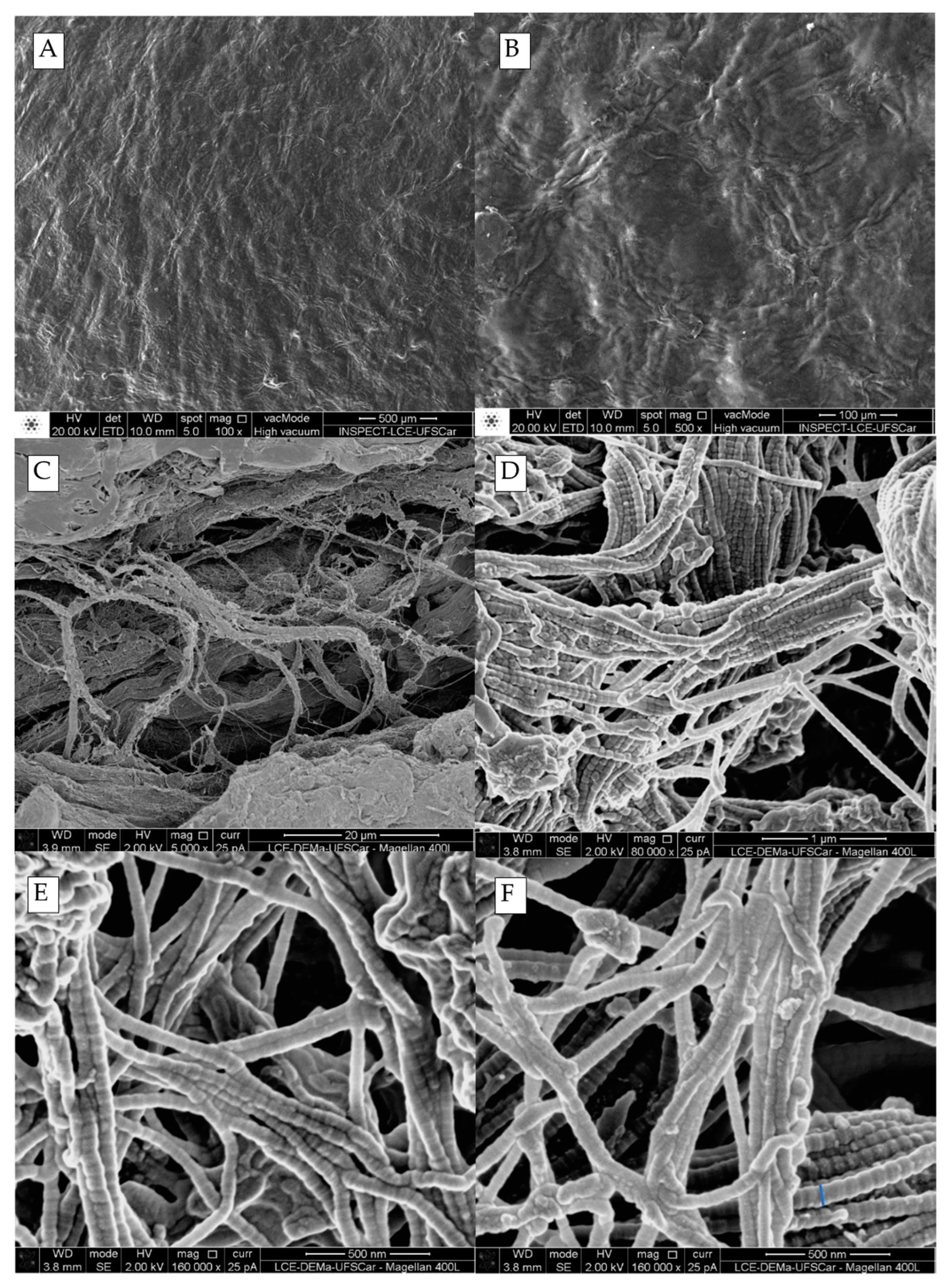
3.6. Scanning Electron Microscopy (SEM) and EDS

SEM was used to determine the surface morphology of the BC membranes (Figure 8A–C) and their nanometric fibers (Figure 8D–F).
As shown in Figure 8A,B, the cellulose membranes have a certain characteristic uniformity. Even at a magnification of 500 X, the nanometric fibers have an appearance similar to waves on the surface and irregular fibrillar arrangements. Tsouko et al. (2015) and Hamed, Maghrawy and Kereem (2023) [62,63] describe similar results.
In contrast, the images taken at the highest magnification (160 KX) (Figure 8E,F) reveal that the fibers have an approximate diameter of 84 nm and do not follow a pattern of organization but are interlaced [64], which enables greater molecule retention capacity [63], especially for large carbon chains, as is the case of oil, whether in free form, dispersed or in an emulsion [5].
The diameter of the bacterial cellulose fibers and their interlaced pattern allow for greater molecule retention capacity; however, it is important to note that the retention of oil molecules, especially those with larger carbon chains, may not be solely due to mechanical filtration. Chemical interactions between the oil molecules and the bacterial cellulose fibers could also contribute to the retention of oil. The interaction between the oil molecules and bacterial cellulose is mainly based on physical adsorption, which is due to the van der Waals forces and electrostatic interactions between the oil molecules and the cellulose fibers [65].
Aliphatic, aromatic and cyclic oil molecules can interact differently with the chemical structure of bacterial cellulose. For example, aromatic molecules, due to their planar structure, can interact more strongly with the cellulose fibers through π–π stacking interactions, while aliphatic molecules can interact mainly through van der Waals forces [66,67]. However, the chemical structure of bacterial cellulose remains relatively unchanged during the filtration process, indicating that the filtration of oily effluents is mainly a mechanical process [5]. The ratio of the oil molecule diameter to the mean void diameter of the membrane is a crucial factor in determining the effectiveness of the filtration system [67].
The SEM analysis demonstrated that the purification process and rinsing after the removal of the membranes from the metabolic broth were effective at removing any microorganisms that may be retained among the fibrils of the membrane, as no bacteria were seen in any of the images. However, the results of EDS assays displayed in Table 4 revealed that this process was not 100% effective [68]. The membranes had a surface mass between 97 and 98% of carbon and oxygen, which are present in the carbon chain of cellulose, and a little more than 1% phosphorus, which is an abundant element in the green tea used as the production medium, remaining even after purification [69].

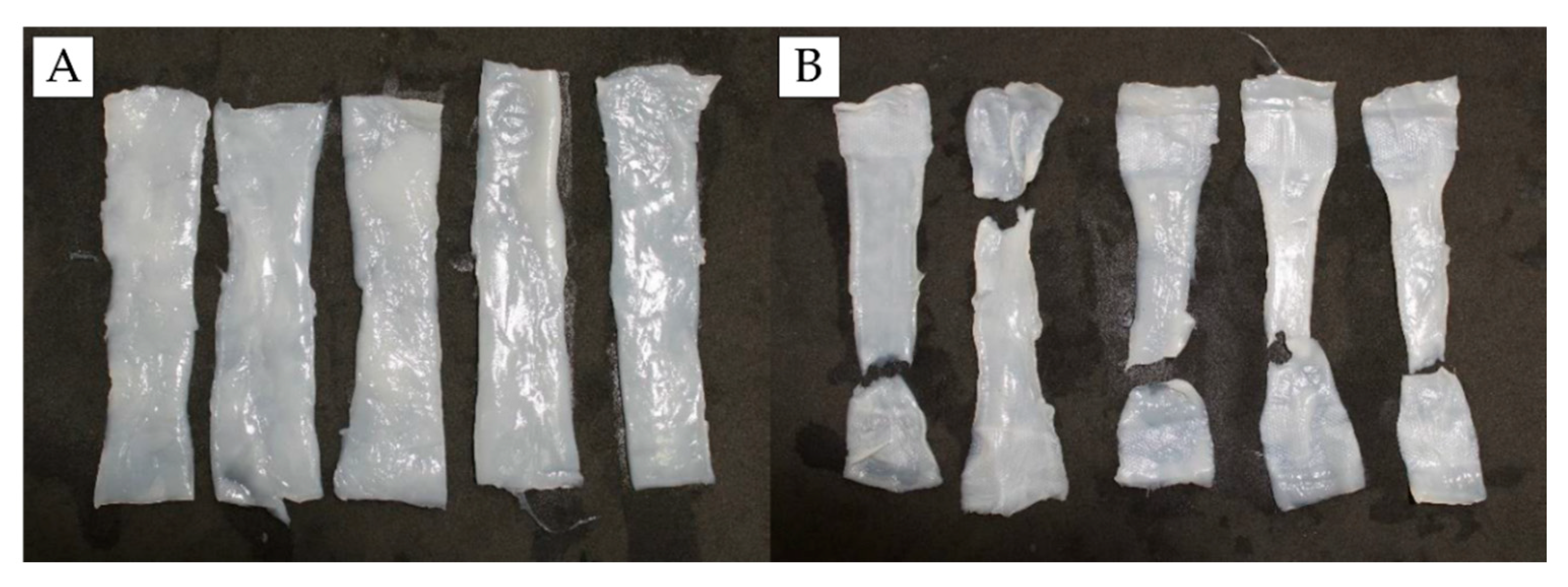
3.7. Mechanical Tests

The mechanical properties of a filtering membrane are directly related to its ideal operating and performance conditions. The results of the mechanical tests (Figure 9) demonstrated that the microbial cellulose membrane resisted a tensile force of 65.53 ± 12.19 Mpa and withstood elongation of 18.91 ± 3.82% before breaking (Figure 10). As shown in the SEM images (Figure 8), the BC membrane obtained after 14 days of fermentation had a dense structure of nanofibers, resulting in a high mechanical strength due to the good interfacial adhesion and strong interactions among the fibers [5].
According to the literature [5,41,70], these values are expected, as high mechanical strength and elongation capacity are typical characteristics of bacterial cellulose. Furthermore, BC is naturally a combination of properties such as high surface area, high polymerization degree and high water-holding capacity [71]. Based on the results, it is safe to assume that the proposed material has ideal characteristics for use as a filtering membrane.

3.8. Compression

The microbial cellular membrane was able to return to its original shape due to the filling of the pores with water. The considerable WRC of a BC membrane enables the free water in its fibrils to be easily pressed out of the nanofibrillar network without damaging its structure (Figure 11).
Figure 12 and Table 5 show that the sample withstood a load of ≈5 kN, could be compressed from a mean thickness of 9.49 ± 2.50 mm to a thickness of 0.66 ± 1.80 mm (≈93% compression rate) and could recover its initial dimension through rehydration. This suggests excellent mechanical strength and elasticity, as shown in Figure 10, and the membrane can absorb and release water under mechanical pressure. According to Chen et al. (2021) [72], this property is not achieved by some traditional polymeric hydrogels, as the absorbed liquids cannot be expelled without damaging the hydrogel due to its weak network or weak bond between polymers. This special characteristic of BC demonstrates its enormous potential for use under compression as a water-filtering membrane.

4. Results and Discussion (Filtering Module)

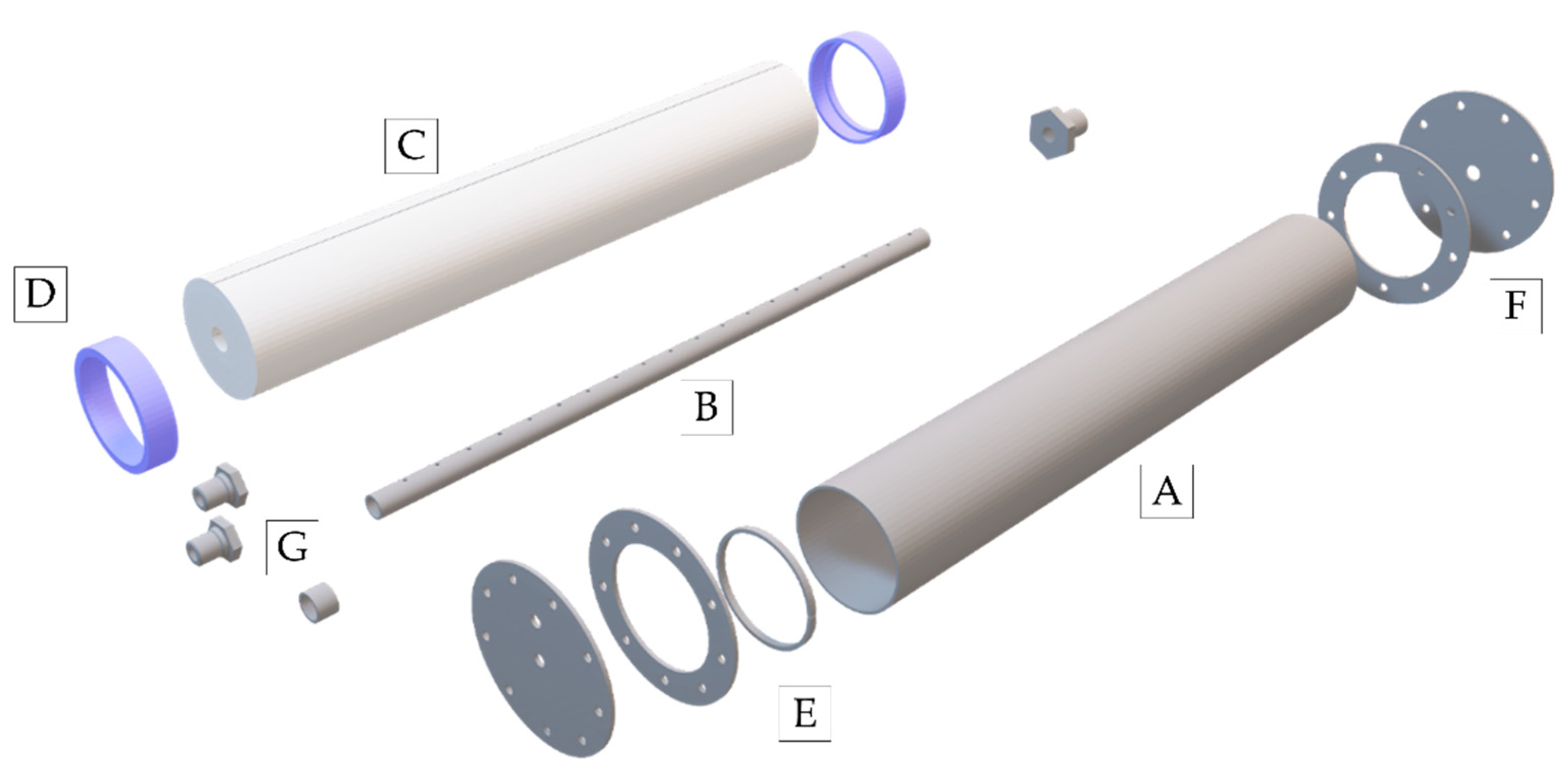
4.1. Three-Dimensional Module

After the finalization of the basic research project and the determination of the best conditions for the support of the membrane (filtering module), a 3D set was assembled to be taken for fabrication part by part. The final product was generated with each of the parts completely independent from the others to enable greater facility in the packaging of the cellulose, maintenance and removal for the replacement of the membrane after reaching maximum saturation. The extruded 3D mold is shown in Figure 13.
The creation of the module with the aid of the computational fluid dynamics software allowed the establishment of the best configuration to make the process occur with the largest filtration area and better retention.
The 3D modeling allowed the possibility to test different design configurations, such as flow channel geometry and arrangement of BC membranes, before physically constructing the device. This ensured that the filtration module was built with the best possible configuration, maximizing filtration efficiency and minimizing potential issues.
A more approximate view is shown in Figure 14, including the internal piping (flute); isolated bacterial cellulose membrane; casing of the membrane, plastic screen and metallic blanket; packing into the internal pipe; and final appearance (external view) of the filtering module.

4.2. Summary Final Configuration (Fabrication and Adaptation of Physical Space)

For fabrication of the pilot prototype, the 3D molds were sent to a specialized company, which fabricated the prototype using the materials stipulated and following the parameters designed.
For the adaptation of the physical space, the fabrication and installation of three platforms were necessary—one fixed for the support of the effluent to be treated and two movable, with different heights and configurations for the support of the filter, its subsystems and the tanks (Figure 15).
Besides the supports, it was necessary to install the recirculation system (Figure 16), which mainly involves the pipes, hoses and connections necessary for the passage of the fluid in the filter and the control of the pressure exerted by the pump in the filtering module. This control is an essential mechanism for the full functioning of the module, as the pump can achieve pressures of up to 10 bar, which could rupture the BC membrane, requiring the interruption of the process, maintenance of the system and replacement of the membrane.
The manufacturing of the BC filter module and the adaptation of the physical space for the start of the tests were necessary to ensure that the filter could be operated safely and efficiently and that the test results were reliable and accurate.

4.3. Membrane Production

The challenges involving the modifications necessary for the production of the membrane after the fluid dynamics studies do not reside in the modification of the culture medium or the percentage of pre-inoculum, but in the control of contamination necessary for the production of a membrane measuring 0.90 × 0.50 × 0.003 m (Figure 17). This aspect of production required the adaptation of the physical space (maintaining the recipient in strategic locations for the reduction in human contact), the use of oxygen passage permission methods (fabrics serving as cover) and methods to avoid the contact of small insects that approached due to the strong sweet smell of the culture medium.

5. Conclusions and Perspectives

The nanofiltration process is the last step of a filtration system. The quality of the filtered water is very high, as the cellulose nanofibers do not allow the passage of large molecules. In particular, bacterial cellulose membranes easily promote the passage of water (hydrophilic) and repel the contact and passage of hydrocarbons (oleophobic).
The membrane has excellent tensile strength but is very flexible and needs to be immersed in water all the time. However, the process requires high pressure, exerting mechanical stress on the membrane and filtering vessel. Thus, the BC membrane proved ideal for this type of process due to its mechanical and physiochemical properties. These conditions were taken into consideration during the development of the filtering module to provide a greater filtration area and, consequently, better pressure distribution and filtration quality.
This prototype will be validated in future studies with contaminated effluents to ensure the effectiveness of the system and process, seeking high treatment quality and possible adaptations. Moreover, evaluations relating the quality of the process to its energy consumption will be necessary. This novel technology is expected to contribute to various industries and the environment as a new way to remediate problems caused by oil contamination in water resources.

Author Contributions

Conceptualization, L.A.S. and A.D.M.d.M.; validation, L.A.S., A.D.M.d.M., C.J.G.d.S.J., J.D.P.d.A., I.J.B.D., R.B.D., Y.d.F.C. and A.F.d.S.C.; writing—original draft preparation, A.D.M.d.M. and C.J.G.d.S.J.; writing—review and editing, A.D.M.d.M., C.J.G.d.S.J., J.D.P.d.A., I.J.B.D., R.B.D., Y.d.F.C., A.F.d.S.C. and L.A.S.; visualization, A.D.M.d.M., C.J.G.d.S.J., A.F.d.S.C. and L.A.S.; supervision, L.A.S.; project administration, L.A.S.; funding acquisition, L.A.S. All authors have read and agreed to the published version of the manuscript.

Funding

This study was funded by the Programa de Pesquisa e Desenvolvimento da Agência Nacional de Energia Elétrica (ANEEL)/Thermoelectric EPESA (Centrais Elétricas de Pernambuco S.A.)/SUAPE Ambiental and by the Brazilian development agencies Fundação de Apoio à Ciência e Tecnologia do Estado de Pernambuco (FACEPE), Conselho Nacional de Desenvolvimento Científico e Tecnológico (CNPq) and Coordenação de Aperfeiçoamento de Pessoal de Nível Superior (CAPES) (Grant n. Finance Code 001).

Data Availability Statement

No new data were created.

Acknowledgments

The authors are grateful to Centro de Ciências e Tecnologia of Universidade Católica de Pernambuco (UNICAP) and Instituto Avançado de Tecnologia e Inovação (IATI), Brazil.

Conflicts of Interest

The authors declare no conflict of interest.

References

  1. Abuhasel, K.; Kchaou, M.; Alquraish, M.; Munusamy, Y.; Jeng, Y.T. Oily Wastewater Treatment: Overview of conventional and modern methods, challenges, and future opportunities. Water 2021, 13, 980. [Google Scholar] [CrossRef]
  2. Dell’anno, F.; Van Zyl, L.J.; Trindade, M.; Buschi, E.; Cannavacciuolo, A.; Pepi, M.; Sansone, C.; Brunet, C.; Ianora, A.; Pascale, D.D. Microbiome enrichment from contaminated marine sediments unveils novel bacterial strains for petroleum hydrocarbon and heavy metal bioremediation. Environ. Pollut. 2023, 317, 120772. [Google Scholar] [CrossRef] [PubMed]
  3. Lázaro-mass, S.; Gómez-Cornelio, S.; Castillo-Vidal, M.; Alvarez-Villagomez, C.S.; Quintana, P.; Larosa-García, S.D. Biodegradation of hydrocarbons from contaminated soils by microbial consortia: A laboratory microcosm study. Electron. J. Biotechnol. 2023, 61, 24–32. [Google Scholar] [CrossRef]
  4. Rocha e Silva, F.C.P.; Rocha e Silva, N.M.P.; Luna, J.M.; Rufino, R.D.; Santos, V.A.; Sarubbo, L.A. Dissolved air flotation combined to biosurfactants: A clean and efficient alternative to treat industrial oily water. Rev. Environ. Sci. Biotechnol. 2018, 17, 591–602. [Google Scholar] [CrossRef]
  5. Galdino, C.J.S.; Maia, A.D.M.; Meira, H.M.; Souza, T.C.; Amorim, J.D.P.; Almeida, F.C.G.; Costa, A.F.S.; Sarubbo, L.A. Use of a bacterial cellulose filter for the removal of oil from wastewater. Process Biochem. 2020, 91, 288–296. [Google Scholar] [CrossRef]
  6. Medeiros, A.D.L.M.; Silva Junior, C.J.G.; de Amorim, J.D.P.; do Nascimento, H.A.; Converti, A.; Costa, A.F.S.; Sarubbo, L.A. Bacterial cellulose for Treatment of Wastewaters Generated by Energy Consuming Industries: A Review. Energies 2021, 14, 5066. [Google Scholar] [CrossRef]
  7. Medeiros, A.D.M.; Silva Junior, C.J.G.; Amorim, J.D.P.; Durval, I.J.B.; Costa, A.F.S.; Sarubbo, L.A. Oily Wastewater Treatment: Methods, Challenges, and Trends. Processes 2022, 10, 743. [Google Scholar] [CrossRef]
  8. Njoku, K.L. Responses of accessions of Zea mays to crude oil pollution using growth indices and enzyme activities as markers. Pollution 2017, 4, 183–193. [Google Scholar] [CrossRef]
  9. Pothula, G.K.; Vij, R.K.; Bera, A. An overview of chemical enhanced oil recovery and its status in India. Pet. Sci. 2023, in press. [Google Scholar] [CrossRef]
  10. El-Gawad, H.S.A. Oil and grease removal from industrial wastewater using new utility approach. Adv. Environ. Chem. 2014, 2014, 916878. [Google Scholar] [CrossRef]
  11. Xia, X.; Ma, J.; Geng, S.; Liu, F.; Yao, M. A review of Oil–Solid Separation and Oil–Water Separation in Unconventional Heavy Oil Production Process. Int. J. Mol. Sci. 2022, 24, 74. [Google Scholar] [CrossRef] [PubMed]
  12. Lehtonen, J.; Chen, X.; Beaumont, M.; Hassinen, J.; Orelma, H.; Dumée, L.F.; Tardy, B.L.; Rojas, O.J. Impact of incubation conditions and post-treatment on the properties of bacterial cellulose membranes for pressure-driven filtration. Carbohydr. Polym. 2021, 251, 117073–117082. [Google Scholar] [CrossRef] [PubMed]
  13. Adetunji, A.I.; Olaniran, A.O. Treatment of industrial oily wastewater by advanced technologies: A review. Appl. Water Sci. 2021, 11, 98. [Google Scholar] [CrossRef]
  14. Cannon, R.; Anderson, S.M. Biogenesis of bacterial cellulose. Crit. Rev. Microbiol. 1991, 17, 435–447. [Google Scholar] [CrossRef]
  15. Rachtanapun, P.; Jantrawut, P.; Klunklin, W.; Jantanasakulwong, K.; Phimolsiripol, Y.; Leksawasdi, N.; Seesuriyachan, P.; Chaiyaso, T.; Insomphun, C.; Phongthai, S. Carboxymethyl bacterial cellulose from nata de coco: Effects of NaOH. Polymers 2021, 13, 348. [Google Scholar] [CrossRef]
  16. Amorim, J.D.P.; Souza, K.C.; Duarte, C.R.; Duarte, I.S.; Ribeiro, F.A.S.; Silva, G.S.; Farias, P.M.A.; Stingl, A.; Costa, A.F.S.; Vinhas, G.M. Plant and bacterial nanocellulose: Production, properties and applications in medicine, food, cosmetics, electronics and engineering. A review. Environ. Chem. Lett. 2020, 18, 851–869. [Google Scholar] [CrossRef]
  17. Amorim, J.D.P.; Silva Junior, C.J.G.; Medeiros, A.D.M.; Nascimento, H.A.; Sarubbo, M.; Medeiros, T.P.M.; Costa, A.F.S.; Sarubbo, L.A. Bacterial Cellulose as a Versatile Biomaterial for Wound Dressing Application. Molecules 2022, 27, 5580. [Google Scholar] [CrossRef]
  18. Silva Junior, C.J.G.; Medeiros, A.D.M.; Amorim, J.D.P.; Nascimento, H.A.; Converti, A.; Costa, A.F.S.; Sarubbo, L.A. Bacterial cellulose biotextiles for the future of sustainable fashion: A review. Environ. Chem. Lett. 2021, 19, 2967–2980. [Google Scholar] [CrossRef]
  19. Carpenter, A.W.; Lannoy, S.-F.; Wiesner, M.R. Cellulose nanomaterials in water treatment technologies. Environ. Sci. Technol. 2015, 49, 5277–5287. [Google Scholar] [CrossRef]
  20. Sai, H.; Fu, R.; Xing, L.; Xiang, J.; Li, Z.; Li, F.; Zhang, T. Surface modification of bacterial cellulose aerogels’ web-like skeleton for oil/water separation. ACS Appl. Mater. Interfaces. 2015, 7, 7373–7738. [Google Scholar] [CrossRef]
  21. Kim, D.; Livazovic, S.; Falca, G.; Nunes, S.P. Oil–Water Separation using Membranes Manufactured from Cellulose/Ionic Liquid Solutions. ACS Sustain. Chem. Eng. 2019, 7, 5649–5659. [Google Scholar] [CrossRef]
  22. Yang, C.; Topuz, F.; Park, S.-H.; Szekely, G. Biobased thin-film composite membranes comprising priamine–genipin selective layer on nanofibrous biodegradable polylactic acid support for oil and solvent-resistant nanofiltration. Green Chem. 2022, 24, 5291–5303. [Google Scholar] [CrossRef]
  23. Alammar, A.; Hardian, R.; Szekely, G. Upcycling agricultural waste into membranes: From date seed biomass to oil and solvent-resistant nanofiltration. Green Chem. 2022, 24, 365–374. [Google Scholar] [CrossRef]
  24. Gao, J.; Wang, J.; Xu, Q.; Wua, S.; Chen, Y. Regenerated cellulose strongly adhered by a supramolecular adhesive onto the PVDF membrane for a highly efficient oil/water separation. Green Chem. 2021, 23, 5633–5646. [Google Scholar] [CrossRef]
  25. Silva Junior, C.J.G.; Amorim, J.D.P.; Medeiros, A.D.M.; Cavalcanti, A.K.L.H.; Nascimento, H.A.; Henrique, M.A.; Maranhão, L.J.C.N.; Vinhas, G.M.; Souto Silva, K.K.O.; Costa, A.F.S.; et al. Design of a Naturally Dyed and Waterproof Biotechnological Leather from Reconstituted Cellulose. J. Funct. Biomater. 2021, 13, 49. [Google Scholar] [CrossRef]
  26. Marin, E.; Rojas, J. Preparation and characterization of crosslinked poly (vinyl) alcohol films with waterproof properties. Int. J. Pharm. Pharm. Sci. 2015, 7, 242–248. [Google Scholar]
  27. Kamiński, K.; Jarosz, M.; Grudzień, J.; Pawlik, J.; Zastawnik, F.; Pandyra, P.; Kołodziejczyk, A.M. Hydrogel bacterial cellulose: A path to improved materials for new eco-friendly textiles. Cellulose 2020, 27, 5353–5365. [Google Scholar] [CrossRef]
  28. Constantino, M.G. Espectroscopia no Infravermelho, 3rd ed.; LTC: Rio de Janeiro, Brazil, 2016. [Google Scholar]
  29. Canevarolo, S.J. Técnicas de Caracterização de Polímeros; Artliber: Sao Paulo, Brazil, 2003. [Google Scholar]
  30. Mothé, C.G.; Azevedo, A.D.D. Análise Térmica de Materiais, 3rd ed.; Artliber: Sao Paulo, Brazil, 2009. [Google Scholar]
  31. Rethwisch, D.G.J.; William, D.C. Ciência e Engenharia de Materiais: Uma Introdução, 9th ed.; LTC: Rio de Janeiro, Brazil, 2016. [Google Scholar]
  32. Dutta, P.; Arun Kumar, G.; Ram, G.; Suneel Varma, D. Spatiotemporal Nonreciprocal Filters: Theoretical Concepts and Literature Review. IEEE Microw. 2022, 23, 85–101. [Google Scholar] [CrossRef]
  33. Altaee, A. Computational model for estimating reverse osmosis system design and performance: Part-one binary feed solution. Desalination 2012, 291, 101–105. [Google Scholar] [CrossRef]
  34. Martínez-Rocamora, A.; Solís-Guzmán, J.; Marrero, M. LCA databases focused on construction materials: A review. Renew. Sust. Energ. Rev. 2016, 58, 565–573. [Google Scholar] [CrossRef]
  35. Augiseau, V.; Barles, S. Studying construction materials flows and stock: A review. Resour. Conserv. Recycl. 2017, 123, 153–164. [Google Scholar] [CrossRef]
  36. Boyko, E.; Stone, H.A. Reciprocal theorem for calculating the flow rate–pressure drop relation for complex fluids in narrow geometries. Phys. Rev. Fluids 2021, 6, L081301. [Google Scholar] [CrossRef]
  37. Kandlikar, S.G.; Garofalo, M.L.; Lu, Z. Water Management in A PEMFC: Water transport mechanism and material degradation in gas diffusion layers. Fuel Cells 2011, 11, 814–823. [Google Scholar] [CrossRef]
  38. Kaboudan, A.; Naderi, M.; Afshar, M.A. The efficiency of Darcy and two-dimensional diffusion flow models to estimate water penetration into concrete. J. Build. Eng. 2021, 34, 102012. [Google Scholar] [CrossRef]
  39. Matsson, J.E. An Introduction to ANSYS Fluent 2022, 1st ed.; SDC Publications: Mission, KS, USA, 2022. [Google Scholar]
  40. Ul-Islam, M.; Khan, S.; Ullah, M.W.; Park, J.K. Comparative study of plant and bacterial cellulose pellicles regenerated from dissolved states. Int. J. Biol. Macromol. 2020, 137, 247–252. [Google Scholar] [CrossRef] [PubMed]
  41. Costa, A.F.S.; Almeida, F.C.G.; Vinhas, G.M.; Sarubbo, L.A. Production of bacterial cellulose by Gluconacetobacter hansenii using corn steep liquor as nutrient sources. Front. Microbiol. 2017, 8, 2017. [Google Scholar] [CrossRef] [PubMed]
  42. Classen, E. Comfort testing of textiles. Adv. Charact. Test. Text. 2018, 59–69. [Google Scholar] [CrossRef]
  43. Nascimento, H.A.; Amorim, J.D.P.; Filho, L.E.P.T.M.; Costa, A.F.S.; Sarubbo, L.A.; Napoleão, D.C.; Vinhas, G.M. Production of bacterial cellulose with antioxidant additive from grape residue with promising cosmetic applications. Polym. Eng. Sci. 2022, 62, 2826–2839. [Google Scholar] [CrossRef]
  44. Tang, W.; Jia, S.; Jia, Y.; Yang, H. The influence of fermentation conditions and post-treatment methods on porosity of bacterial cellulose membrane. World J. Microbiol. Biotechnol. 2010, 26, 125–131. [Google Scholar] [CrossRef]
  45. Indrarti, L.; Indriyati, I.; Syampurwadi, A.; Pujiastuti, S. Physical and mechanical properties of modified bacterial cellulose composite films. In AIP Conference Proceedings; AIP Publishing: New York, NY, USA, 2016; Volume 1711, p. 050007. [Google Scholar] [CrossRef]
  46. Revin, V.V.; Dolganov, A.V.; Liyaskina, E.V.; Nazarova, N.B.; Balandina, A.V.; Devyataeva, A.A.; Revin, V.D. Characterizing Bacterial Cellulose Produced by Komagataeibacter sucrofermentans H-110 on Molasses Medium and Obtaining a Biocomposite Based on It for the Adsorption of Fluoride. Polymers 2021, 13, 1422. [Google Scholar] [CrossRef]
  47. Gayathry, G.; Gopalaswamy, G. Production and characterisation of microbial cellulosic fibre from Acetobacter xylinum. Indian J. Fibre Text. Res. 2014, 39, 93–96. [Google Scholar]
  48. Shi, Z.; Xu, G.; Deng, J.; Dong, M.; Murugadoss, V.; Liu, C.; Shao, Q.; Wu, S.; Guo, Z. Structural characterization of lignin from D. sinicus by FTIR and NMR techniques. Green Chem. Lett. Rev. 2019, 12, 235–243. [Google Scholar] [CrossRef]
  49. Ashori, A.; Sheykhnazari, S.; Tabarsa, T.; Shakeri, A.; Golalipour, M. Bacterial cellulose/silica nanocomposites: Preparation and characterization. Carbohydr. Polym. 2012, 90, 413–418. [Google Scholar] [CrossRef] [PubMed]
  50. Redjala, S.; Ferhoum, R.; Aït Hocine, N.; Azem, S. Degradation of Polycarbonate Properties Under Thermal Aging. J Fail. Anal. Preven. 2019, 19, 536–542. [Google Scholar] [CrossRef]
  51. Zhu, P.; Sui, S.; Wang, B.; Sun, K.; Sun, G. A study of pyrolysis and pyrolysis products of flame-retardant cotton fabrics by DSC, TGA, and PY–GC–MS. J. Anal. Appl. Pyrolysis. 2004, 71, 645–655. [Google Scholar] [CrossRef]
  52. Zhao, M.; Qi, Z.; Tao, X.; Newkirk, C.; Hu, X.; Lu, S. Chemical, Thermal, Time, and Enzymatic Stability of Silk Materials with Silk I Structure. Int. J. Mol. Sci. 2021, 22, 4136. [Google Scholar] [CrossRef]
  53. Xu, K.; Li, Q.; Xie, L.; Shi, Z.; Su, G.; Harper, D.; Tang, Z.; Zhou, J.; Du, G.; Wang, S. Novel flexible, strong, thermal-stable, and high-barrier switchgrass-based lignin-containing cellulose nanofibrils/chitosan biocomposites for food packaging. Ind. Crop. Prod. 2022, 179, 114661. [Google Scholar] [CrossRef]
  54. Kumar, V.; Sharma, D.K.; Bansal, V.; Mehta, D.; Sangwan, R.S.; Yadav, S.K. Efficient and economic process for the production of bacterial cellulose from isolated strain of Acetobacter pasteurianus of RSV-4 bacterium. Bioresour. Technol. 2019, 275, 430–433. [Google Scholar] [CrossRef]
  55. Gea, S.; Reynolds, C.T.; Roohpour, N.; Wirjosentono, B.; Soykeabkaew, N.; Bilotti, E.; Peijs, T. Investigation into the structural, morphological, mechanical and thermal behaviour of bacterial cellulose after a two-step purification process. Bioresour. Technol. 2011, 102, 9105–9110. [Google Scholar] [CrossRef]
  56. Souza, E.F.; Furtado, M.R.; Carvalho, C.W.P.; Freitas-Silva, O.; Gottschalk, L.M.F. Production and characterization of Gluconacetobacter xylinus bacterial cellulose using cashew apple juice and soybean molasses. Int. J. Biol. Macromol. 2020, 146, 285–289. [Google Scholar] [CrossRef]
  57. Leonarski, E.; Cesca, K.; Zanella, E.; Stambuk, B.U.; Oliveira, D.; Poletto, P. Production of kombucha-like beverage and bacterial cellulose by acerola byproduct as raw material. Lwt 2021, 135, 110075. [Google Scholar] [CrossRef]
  58. Avcioglu, N.H.; Birben, M.; Bilkay, I.S. Optimization and physicochemical characterization of enhanced microbial cellulose production with a new Kombucha consortium. Process Biochem. 2021, 108, 60–68. [Google Scholar] [CrossRef]
  59. Li, J.; Chen, G.; Zhang, R.; Wu, H.; Zeng, W.; Liang, Z. Production of high crystallinity type-I cellulose from Komagataeibacter hansenii JR-02 isolated from Kombucha tea. Biotechnol. Appl. Biochem. 2019, 66, 108–118. [Google Scholar] [CrossRef]
  60. Adepu, S.; Khandelwal, M. Ex-situ modification of bacterial cellulose for immediate and sustained drug release with insights into release mechanism. Carb. Polym. 2020, 249, 116816. [Google Scholar] [CrossRef]
  61. Brazel, C. Dimensionless analysis of swelling of hydrophilic glassy polymers with subsequent drug release from relaxing structures. Biomaterials 1999, 20, 721–732. [Google Scholar] [CrossRef]
  62. Tsouko, E.; Kourmentza, C.; Ladakis, D.; Kopsahelis, N.; Mandala, I.; Papanikolaou, S.; Paloukis, F.; Alves, V.; Koutinas, A. Bacterial Cellulose Production from Industrial Waste and by-Product Streams. Int. J. Mol. Sci. 2015, 16, 14832–14849. [Google Scholar] [CrossRef] [PubMed]
  63. Hamed, D.A.; Maghrawy, H.H.; Kareem, H.A. Biosynthesis of bacterial cellulose nanofibrils in black tea media by a symbiotic culture of bacteria and yeast isolated from commercial kombucha beverage. World J. Microbiol. Biotechnol. 2022, 39, 48. [Google Scholar] [CrossRef]
  64. Digel, I.; Akimbekov, N.; Rogachev, E.; Pogorelova, N. Bacterial cellulose produced by Medusomyces gisevii on glucose and sucrose: Biosynthesis and structural properties. Res. Sq. 2023. [Google Scholar] [CrossRef]
  65. Hassan, E.; Hassan, M.; Abou-Zeid, R.; Berglund, L.; Oksman, K. Use of bacterial cellulose and crosslinked cellulose nanofibers membranes for removal of oil from oil-in-water emulsions. Polymers 2017, 9, 388. [Google Scholar] [CrossRef]
  66. Li, Z.; Wang, M.; Li, Y.; Ren, J.; Pei, C. Effect of cellulose nanocrystals on bacterial cellulose hydrogel for oil-water separation. Sep. Purif. Technol. 2023, 304, 122349. [Google Scholar] [CrossRef]
  67. Wang, Y.; Yadav, S.; Heinlein, T.; Konjik, V.; Breitzke, H.; Buntkowsky, G.; Schneider, J.J.; Zhang, K. Ultra-light nanocomposite aerogels of bacterial cellulose and reduced graphene oxide for specific absorption and separation of organic liquids. RSC Adv. 2014, 4, 21553–21558. [Google Scholar] [CrossRef]
  68. Mohammadkazemi, F.; Doosthoseini, K.; Azin, M. Effect of ethanol and medium on bacterial cellulose (BC) production by Gluconacetobacter xylinus (ptcc 1734). Cellul. Chem. Technol. 2014, 49, 455–462. [Google Scholar]
  69. Grande, C.J.; Torres, F.G.; Gomez, C.M.; Bañó, M.C. Nanocomposites of bacterial cellulose/hydroxyapatite for biomedical applications. Acta Biomater. 2009, 5, 1605–1615. [Google Scholar] [CrossRef]
  70. Liu, K.; Catchmark, J.M. Enhanced mechanical properties of bacterial cellulose nanocomposites produced by co-culturing Gluconacetobacter hansenii and Escherichia coli under static conditions. Carb. Polym. 2019, 219, 12–20. [Google Scholar] [CrossRef] [PubMed]
  71. Gorgieva, S.; Trček, J. Bacterial Cellulose: Production, Modification and Perspectives in Biomedical Applications. Nanomaterials 2019, 9, 1352. [Google Scholar] [CrossRef]
  72. Cheng, Z.; Duan, C.; Zeng, J.; Wang, B.; Xu, J.; Gao, W.; Li, J.; Chen, K. Bottom-Up Ecofriendly Strategy for Construction of Sustainable Bacterial Cellulose Bioaerogel with Multifunctional Properties. Adv. Mater. Interfaces. 2021, 8, 2002101. [Google Scholar] [CrossRef]
Figure 1. Technical drawing with specifications for tank supports and materials for filtration subsystems.
Water 15 02025 g001
Figure 2. Rectangular glass container measuring 0.90 × 0.50 × 0.15 m for production of BC membrane.
Water 15 02025 g002
Figure 3. BC membrane with moisture completely removed.
Water 15 02025 g003
Figure 4. Bacterial cellulose membrane produced for 14 days in Schott flasks.
Water 15 02025 g004
Figure 5. Infrared spectrum of BC membranes.
Water 15 02025 g005
Figure 6. TG (-) and DTG (-) curves of bacterial cellulose membranes.
Water 15 02025 g006
Figure 7. X-ray diffractogram of bacterial cellulose samples.
Water 15 02025 g007
Figure 8. SEM images of BC membrane at magnification of (A) 100 X, (B) 500 X, (C) 5 KX, (D) 80 KX, (E) 160 KX and (F) 160 KX.
Water 15 02025 g008
Figure 9. Mechanical tests of bacterial cellulose: tensile strength (MPa) and elongation at breaking point (%).
Water 15 02025 g009
Figure 10. Bacterial cellulose samples: (A) before and (B) after mechanical tests.
Water 15 02025 g010
Figure 11. Bacterial cellulose samples (A) before and (B) after compression test.
Water 15 02025 g011
Figure 12. Load Curves × Sample Displacement.
Water 15 02025 g012
Figure 13. The 3D mold of membrane support for filtration: (A) external piping, (B) internal piping, (C) bundled membrane and wire mesh, (D) internal sealing supports, (E) external sealing support, (F) flanges and (G) fluid inlet and outlet connection pins.
Water 15 02025 g013
Figure 14. The 3D mold of membrane support for filtration: (A) internal piping; (B) bacterial cellulose membrane; (C) casing of membrane, plastic screen and metallic blankets; (D) packing into internal piping; and (E) final appearance (external view) of filtering module.
Water 15 02025 g014
Figure 15. Filter operational subsystems: (A) structural platform for tank with effluent to be treated, (B) peristaltic pump, (C) support table, (D) pressure regulator connected to pressure gauges, (E) filtration module, (F) pressure gauges for output pressure control and (G) tanks for disposal of treated and waste effluents.
Water 15 02025 g015
Figure 16. Recirculation system developed to regulate fluid inlet pressure in the filtration system.
Water 15 02025 g016
Figure 17. BC membrane produced in containers of rectangular shape of 0.90 × 0.50 × 0.15 m.
Water 15 02025 g017
Table 1. Bacterial cellulose production yield and water retention capacity (WRC).
BC 14 DaysMean (g/L) ± Standard DeviationWRC (%) ± Standard Deviation
Wet weight436.12 ± 17.0397.65 ± 0.36
Dry weight10.24 ± 1.49
Table 2. Chemical groups in BC sample.
Wave Number (cm−1)Characteristic Group
3337Axial deformation of O-H
2893Axial deformation of CH2
1636Deformation of C=C
1427Angular deformation of CH2
1314Angular deformation of CH
1161Stretching of C-O-C
1108Stretching of C-O-C
1032Deformation of C-O
Table 3. Summary of TGA results.
Temperature Range (°C)Loss of Mass (%)Residual Stable to 800 °C (%)
23 to 2455.72
245 to 40052.1027.39
400 to 80014.80
Table 4. EDS results of bacterial cellulose samples.
ElementMass of Elements (%)
ABCDEF
C52.8864.1052.8252.6153.4652.40
O45.4833.3445.9146.0945.1646.44
P1.642.561.281.301.381.16
Table 5. Compression test results.
SampleMaximum Load (N)Displacement under Maximum Load (mm)Deformation under Maximum Load (%)
14619.928.4091.51
24497.267.0488.55
34499.0511.8297.52
44898.979.0792.78
54898.257.8491.63
Mean4682.698.8392.40
Standard deviation203.281.8314.13
Disclaimer/Publisher’s Note: The statements, opinions and data contained in all publications are solely those of the individual author(s) and contributor(s) and not of MDPI and/or the editor(s). MDPI and/or the editor(s) disclaim responsibility for any injury to people or property resulting from any ideas, methods, instructions or products referred to in the content.

