
Physical Modeling of Beveled-Face Stepped Chute


Abstract
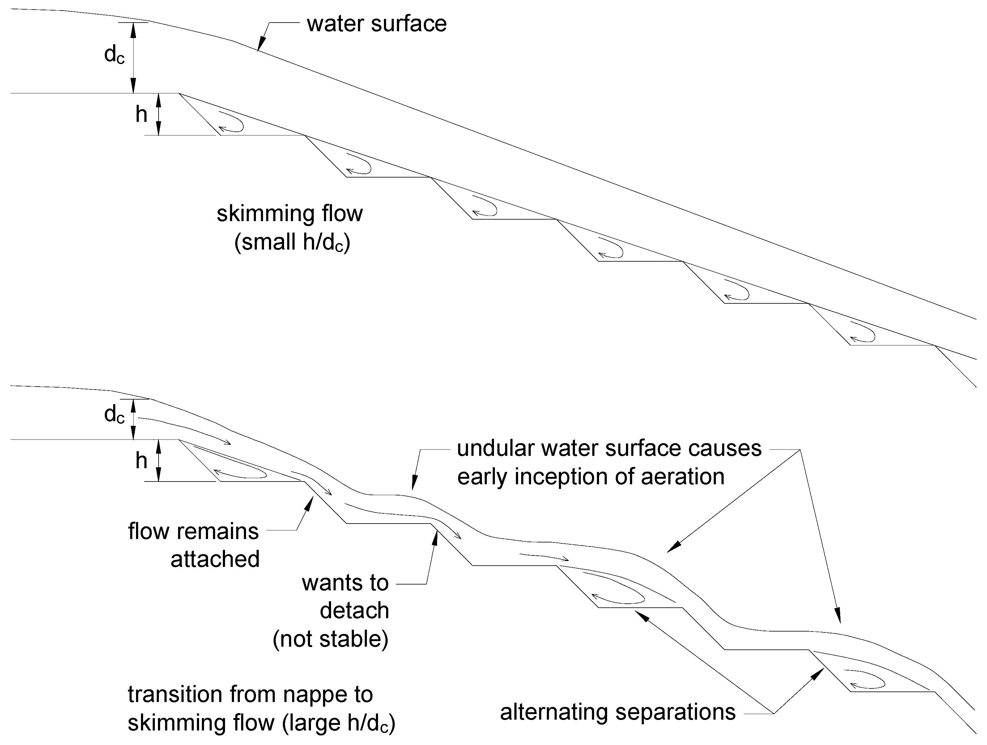
:1. Introduction
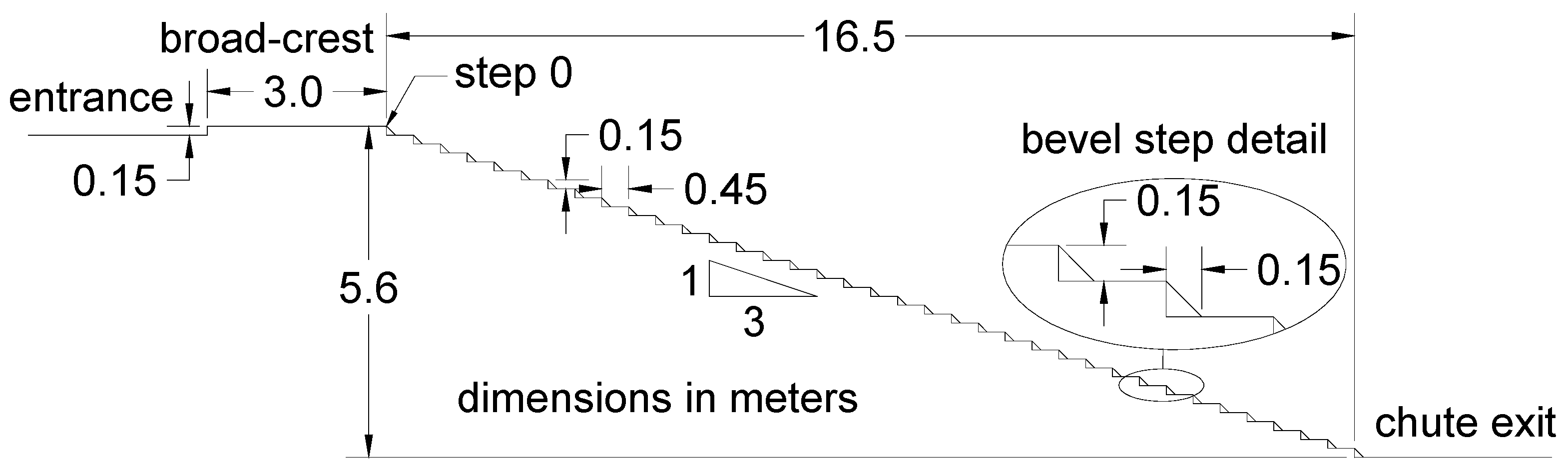
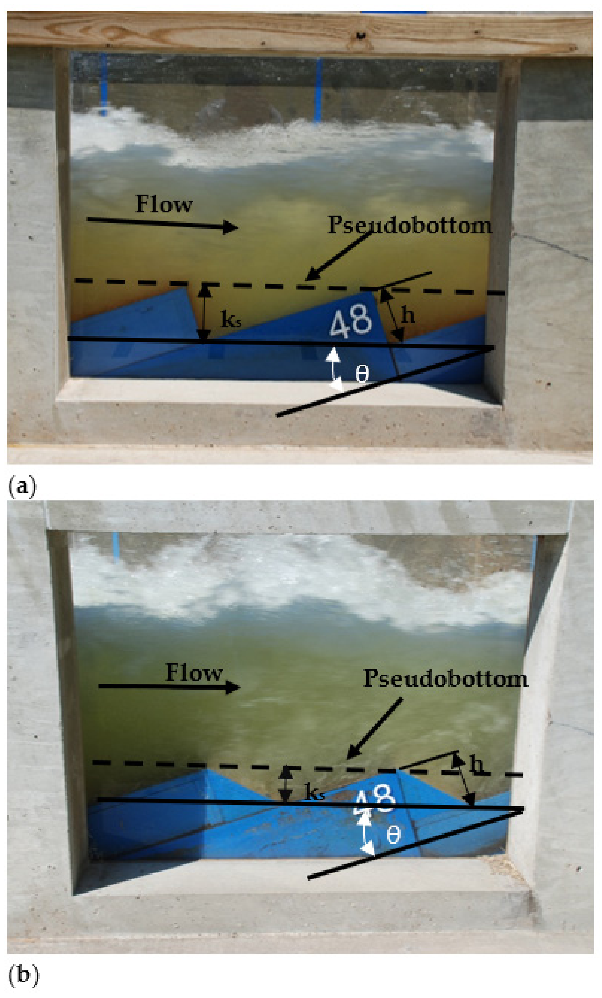
2. Materials and Methods
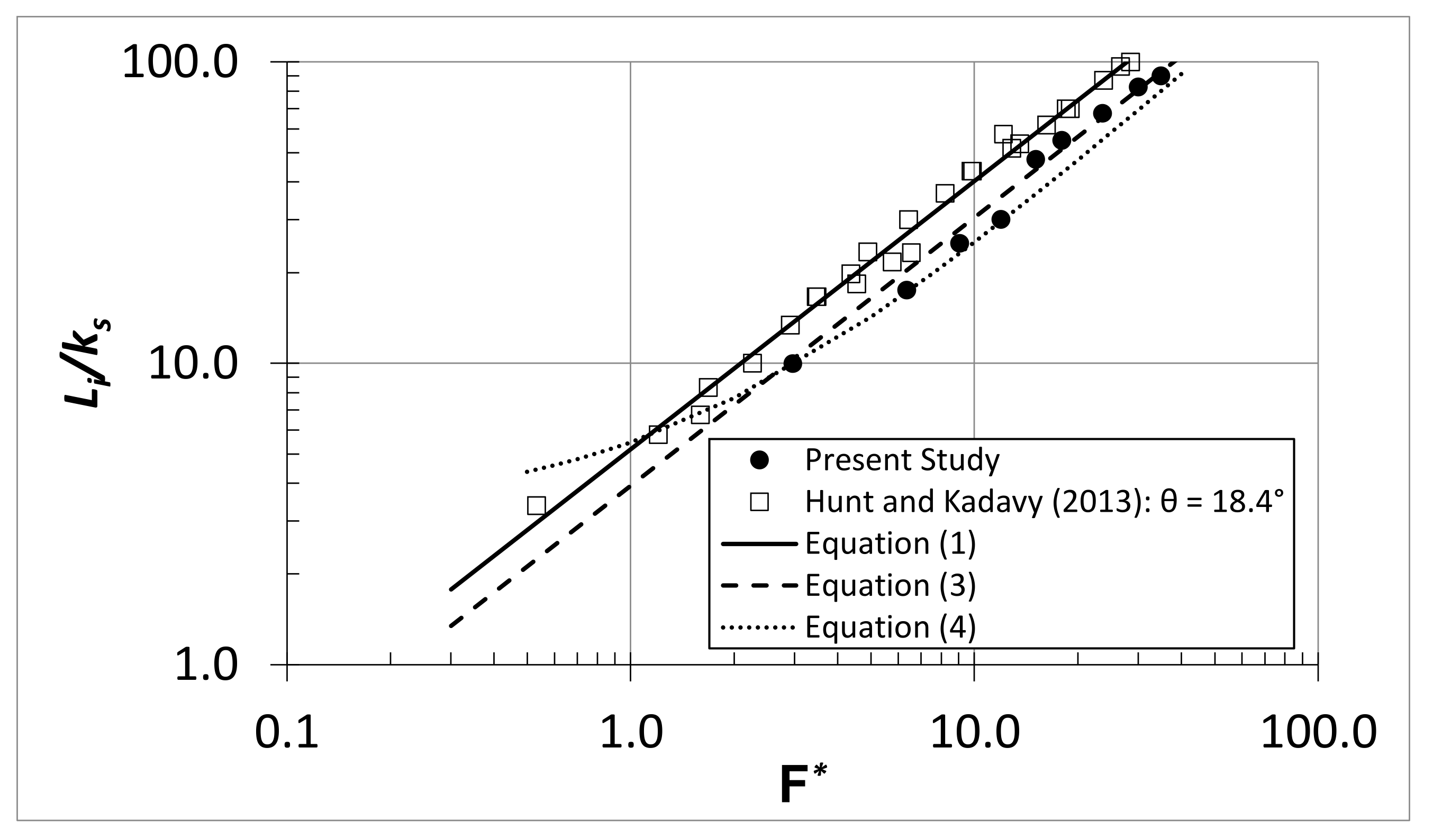
3. Free-Surface Inception Point
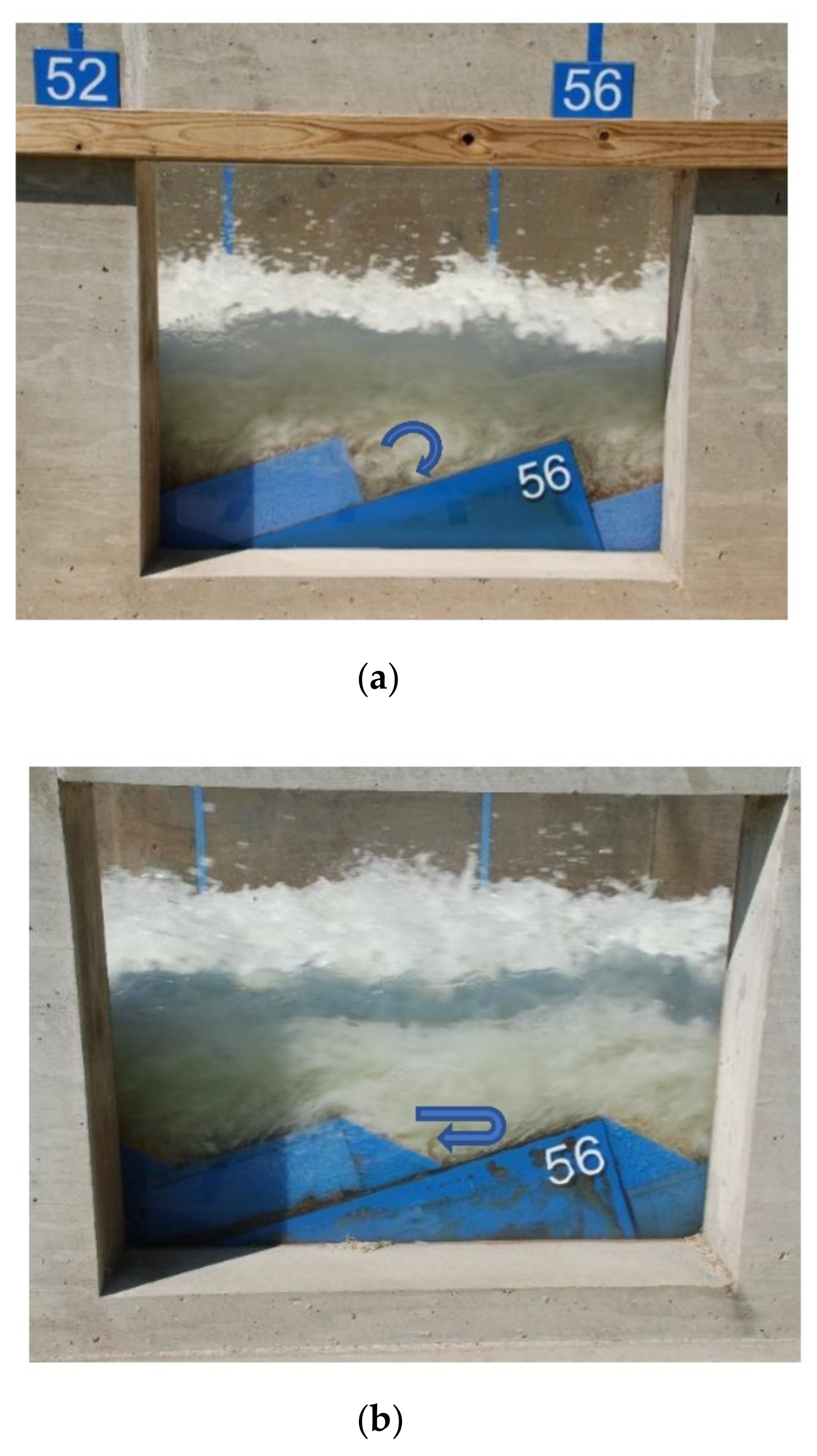
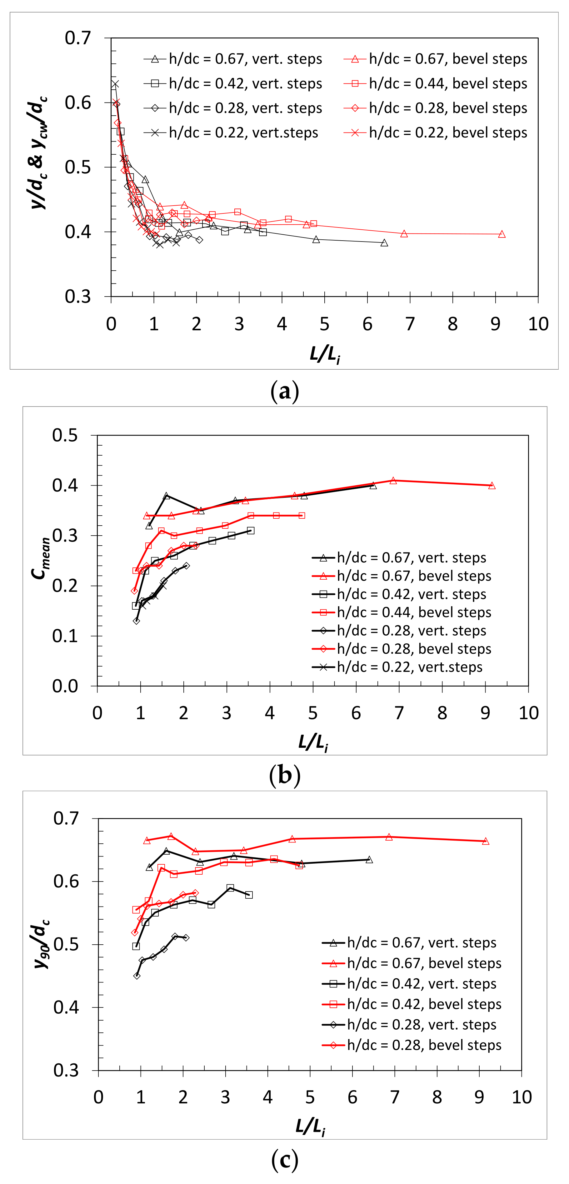
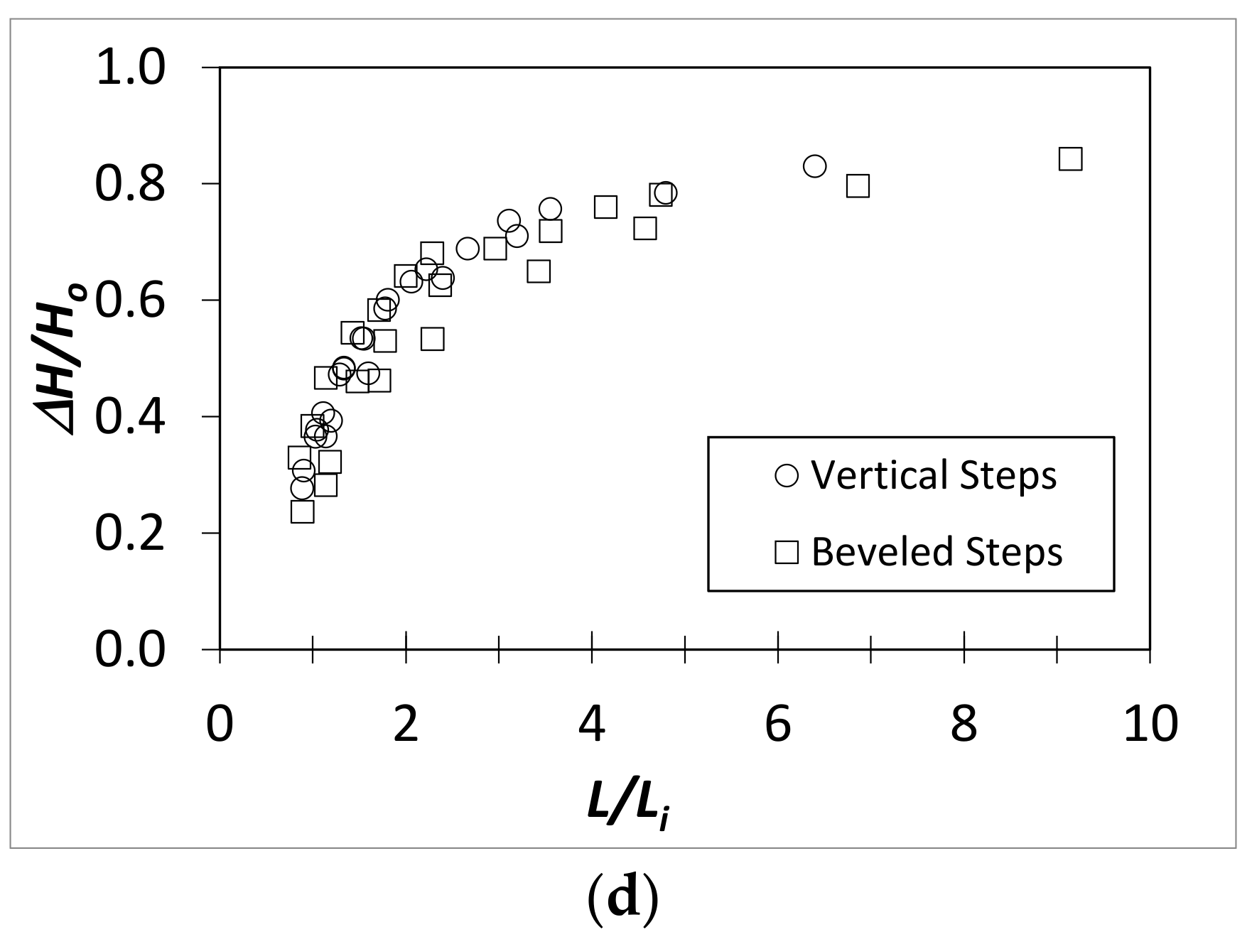
4. Results
5. Discussion and Conclusions
Author Contributions
Funding
Data Availability Statement
Acknowledgments
Conflicts of Interest
Abbreviations
| Notation | |
| A | area; |
| Cf | correction factor to the free-surface inception point for beveled face steps; |
| Cmean | mean air concentration; |
| dc | critical flow depth; |
| F* | Froude number defined in terms of roughness height: q/[g(sinθ)ks3]0.5; |
| g | gravitational constant; |
| h | step height; |
| h/dc | step height to critical flow depth ratio; |
| H | specific energy (e.g., ); |
| Hcrest | total drop height from the weir crest to the measurement location step surface; |
| Ho | total energy at the crest relative to the measurement location step surface (e.g., Ho = Hcrest + 1.5dc); |
| ks | the surface roughness = hcos(θ) for vertical face steps and = [(z − 1)/z]hcos(θ) for beveled face steps; |
| L | length from the downstream edge of the broad-crested weir to the point of interest; |
| L/Li | normalized length; |
| Li | characteristic length from the downstream edge of the broad-crested weir to the surface inception point; |
| q | unit discharge; |
| R | Reynolds number = q/vk; |
| vk | kinematic viscosity; |
| V | mean velocity; |
| v | velocity for an incremental area in the velocity profile; |
| y | flow depth, normal coordinate from pseudobottom; |
| ycw | equivalent clear water flow depth; |
| y90 | characteristic flow depth where the air concentration is 90%; |
| z | 1/tan(θ) for 45° beveled face steps; |
| α | energy coefficient, ; |
| ΔA | incremental area; |
| ΔH | total energy loss, ΔH = Ho − H; |
| ΔH/Ho | relative energy loss, (e.g., ΔH/Ho = 1 − (H/Ho)); |
| θ | chute slope; |
| Acronyms | |
| H | horizontal; |
| NRCS | Natural Resources Conservation Service; |
| RCC | roller compacted concrete; |
| USDA | United States Department of Agriculture; |
| V | vertical. |
References
- Chanson, H. Hydraulics of skimming flows over stepped channels and spillways. IAHR J. Hydraul. Res. 1994, 32, 445–460. [Google Scholar] [CrossRef] [Green Version]
- Chanson, H. The Hydraulics of Stepped Chutes and Spillways; A. A. Balkema Publishers: Steenwijk, The Netherlands, 2002. [Google Scholar]
- Boes, R.M.; Hager, W.H. Two-phase flow characteristics of stepped spillways. J. Hydraul. Eng. 2003, 129, 661–670. [Google Scholar] [CrossRef]
- Gonzalez, C. An Experimental Study of Free-Surface Aeration on Embankment Stepped Chutes. Ph.D. Thesis, University of Queensland, Brisbane, Australia, 2005. [Google Scholar]
- Meireles, I.; Matos, J. Skimming flow in the nonaerated region of stepped spillways over embankment dams. J. Hydraul. Eng. 2009, 135, 685–689. [Google Scholar] [CrossRef]
- Hunt, S.L.; Kadavy, K.C. Inception point for embankment dam stepped spillways. J. Hydraul. Eng. 2013, 139, 60–64. [Google Scholar] [CrossRef]
- Hunt, S.L.; Kadavy, K.C. Estimated splash and training wall height requirements for stepped chutes applied to embankment dams. J. Hydraul. Eng. 2017, 143, 06017018. [Google Scholar] [CrossRef]
- Hunt, S.L.; Kadavy, K.C. Inception point for stepped chute designs with multiple sections of different step heights. J. Hydraul. Eng. 2021, 147, 06021001. [Google Scholar] [CrossRef]
- Cheng, X.; Gulliver, J.S.; Zhu, D. Application of displacement height and surface roughness length to determination boundary layer development length over stepped spillway. Water 2014, 6, 3888–3912. [Google Scholar] [CrossRef] [Green Version]
- Hunt, S.L.; Kadavy, K.C.; Hanson, G.J. Simplistic design methods for moderate-sloped stepped chutes. J. Hydraul. Eng. 2014, 140, 04014062. [Google Scholar] [CrossRef]
- Zhang, G.; Chanson, H. Hydraulics of the developing flow region of stepped spillways. I: Physical modeling and boundary layer development. J. Hydraul. Eng. 2016, 142, 04016016. [Google Scholar] [CrossRef] [Green Version]
- Relvas, A.T.; Pinheiro, A.N. Inception point and air concentration in flows on stepped chutes lined with wedge-shaped concrete blocks. J. Hydraul. Eng. 2008, 134, 1042–1051. [Google Scholar] [CrossRef]
- Bung, D.B.; Schlenkhoff, A. Self-aerated skimming flow on embankment stepped spillways—The effect of additional micro-roughness on energy dissipation and oxygen transfer. In Proceedings of the 1st IAHR European Congress, Edinburgh, Scotland, 4–6 May 2010; p. 6. [Google Scholar]
- Felder, S.; Chanson, H. Air-water flows and free-surface profiles on a non-uniform stepped chute. J. Hydraul. Res. IAHR 2014, 52, 253–263. [Google Scholar] [CrossRef] [Green Version]
- Felder, S.; Chanson, H. Effects of step pool porosity upon flow aeration and energy dissipation on pooled stepped spillways. J. Hydraul. Eng. 2014, 140, 04014002. [Google Scholar] [CrossRef] [Green Version]
- Felder, S.; Chanson, H. Simple design criterion for residual energy on embankment dam stepped spillways. J. Hydraul. Eng. 2016, 142, 04015062. [Google Scholar] [CrossRef] [Green Version]
- Stephenson, D. Stepped energy dissipators. In Proceedings of the International Symposium on Hydraulics for High Dams, IAHR, Beijing, China, 15–18 November 1988; pp. 1228–1235. [Google Scholar]
- André, S. High Velocity Aerated Flow on Stepped Chutes with Macro-Roughness Elements. Ph.D. Thesis, Communication LCH20, École Polytechnique Fédérale de Lausanne (EPFL), Lausanne, Switzerland, 2004. [Google Scholar]
- André, S.; Matos, J.; Boillat, J.L.; Schleiss, A.J. Energy dissipation and hydrodynamic forces of aerated flow over macro-roughness linings for overtopped embankment dams. In Proceedings of the International Conference on Hydraulics of Dams and River Structures, Tehran, Iran, 26–28 April 2004; Yazdandoost, F., Attari, J., Eds.; Taylor and Francis: London, UK, 2004; pp. 189–196. [Google Scholar]
- Gonzalez, C.A.; Chanson, H. Hydraulic design of stepped spillways and downstream energy dissipators for embankment dams. Dam Eng. 2007, 17, 223–243. [Google Scholar]
- Gonzalez, C.A.; Takahashi, M.; Chanson, H. An experimental study of effects of step roughness in skimming flows on stepped chutes. J. Hydraul. Res. 2008, 46, 24–35. [Google Scholar] [CrossRef] [Green Version]
- Zare, H.K.; Doering, J.C. Inception point of air entrainment and training wall characteristics of baffles and sills on stepped spillways. J. Hydraul. Eng. 2012, 138, 1119–1124. [Google Scholar] [CrossRef]
- Zhang, G.; Chanson, H. Effects of step and cavity shapes and aeration and energy dissipation performances of stepped chutes. J. Hydraul. Eng. 2018, 144, 04018060. [Google Scholar] [CrossRef] [Green Version]
- Daneshfaraz, R.; Aminvash, E.; Bagherzadeh, M.; Ghaderi Am Kriqi, A.; Najibi, A.; Ricardo, A.M. Laboratory investigation of hydraulic parameters on inclined drop equipped with fishway elements. Symmetry 2021, 13, 1643. [Google Scholar] [CrossRef]
- Daneshfaraz, R.; Aminvash, E.; Ghaderi, A.; Kuriqi, A.; Abraham, J. Three-dimensional investigation of hydraulic properties of vertical drop in the presence of step and grid dissipators. Symmetry 2021, 13, 895. [Google Scholar] [CrossRef]
- Meireles, I.; Renna, F.; Matos, J.; Bombardelli, F.A. Skimming, nonaerated flow on stepped spillways over roller compacted concrete dams. J. Hydraul. Eng. 2012, 138, 870–877. [Google Scholar] [CrossRef]
- Chow, V.T. Open-Channel Hydraulics; McGraw-Hill, Book Company, Inc.: Boston, MA, USA, 1959. [Google Scholar]
- Hunt, S.L.; Kadavy, K.C. Lesson learned in stepped chute instrumentation. Appl. Eng. Agric. 2021, 37, 513–521. [Google Scholar] [CrossRef]
- Lane, E. Entrainment of air in swiftly flowing water. Civil Eng. 1939, 9, 88–91. [Google Scholar]
- Halbronn, G. Etude de la mise en régime des écoulements sur les ouvrages à forte pente. Houille Blanche 1952, 38, 347–371. [Google Scholar] [CrossRef] [Green Version]
- Bauer, W.J. Turbulent boundary layer on steep slopes. Trans. Am. Soc. Civil Eng. 1954, 119, 1212–1233. [Google Scholar] [CrossRef]
- Wood, I.R.; Ackers, P.; Loveless, J. General method for critical point on spillways. J. Hydraul. Eng. 1983, 109, 308–312. [Google Scholar] [CrossRef]
- Pfister, M.; Hager, W.H. Self-entrainment of air on stepped spillways. Int. J. Multiph. Flow 2011, 37, 99–107. [Google Scholar] [CrossRef]
- Takahashi, M.; Ohtsu, I. Aerated flow characteristics of skimming flow over stepped chutes. J. Hydr. Res. 2012, 50, 51–60. [Google Scholar] [CrossRef]


| q (m2/s) | dc (m) | h/dc | R | Flow Description |
|---|---|---|---|---|
| 0.16 | 0.14 | 1.13 | 1.39 × 10⁵ | nappe/transition |
| 0.34 | 0.23 | 0.68 | 2.99 × 10⁵ | skimming |
| 0.48 | 0.29 | 0.53 | 4.26 × 10⁵ | skimming |
| 0.63 | 0.34 | 0.44 | 5.63 × 10⁵ | skimming |
| 0.80 | 0.40 | 0.38 | 7.10 × 10⁵ | skimming |
| 0.95 | 0.45 | 0.34 | 8.45 × 10⁵ | skimming |
| 1.24 | 0.54 | 0.28 | 1.11 × 10⁶ | skimming |
| 1.58 | 0.63 | 0.24 | 1.41 × 10⁶ | skimming |
| 1.84 | 0.70 | 0.22 | 1.64 × 10⁶ | skimming |
| Beveled-Face Steps | Vertical-Face Steps [6] | |||||||
|---|---|---|---|---|---|---|---|---|
| q (m2/s) | Inception Point (Step Number) | Li (m) | ks (m) | F* | Li/ks | ks (m) | F* | Li/ks |
| 0.16 | 4 | 0.96 | 0.096 | 3 | 10 | 0.14 | 1.6 | 6.7 |
| 0.34 | 7 | 1.7 | 0.096 | 6.4 | 18 | 0.14 | 3.5 | 17 |
| 0.48 | 10 | 2.4 | 0.096 | 9 | 25 | 0.14 | 4.9 | 23 |
| 0.63 | 12 | 2.9 | 0.096 | 12 | 30 | 0.14 | 6.4 | 30 |
| 0.8 | 19 | 4.6 | 0.096 | 15 | 48 | 0.14 | 8.2 | 37 |
| 0.95 | 22 | 5.3 | 0.096 | 18 | 55 | 0.14 | 9.8 | 43 |
| 1.24 | 27 | 6.5 | 0.096 | 24 | 68 | 0.14 | 13 | 52 |
| 1.58 | 33 | 8 | 0.096 | 30 | 83 | 0.14 | 16 | 62 |
| 1.84 | 36 | 8.7 | 0.096 | 35 | 90 | 0.14 | 19 | 70 |
Publisher’s Note: MDPI stays neutral with regard to jurisdictional claims in published maps and institutional affiliations. |
© 2022 by the authors. Licensee MDPI, Basel, Switzerland. This article is an open access article distributed under the terms and conditions of the Creative Commons Attribution (CC BY) license (https://creativecommons.org/licenses/by/4.0/).
Share and Cite
Hunt, S.L.; Kadavy, K.C.; Wahl, T.L.; Moses, D.W. Physical Modeling of Beveled-Face Stepped Chute. Water 2022, 14, 365. https://doi.org/10.3390/w14030365
Hunt SL, Kadavy KC, Wahl TL, Moses DW. Physical Modeling of Beveled-Face Stepped Chute. Water. 2022; 14(3):365. https://doi.org/10.3390/w14030365
Chicago/Turabian StyleHunt, Sherry L., Kem C. Kadavy, Tony L. Wahl, and Dana W. Moses. 2022. "Physical Modeling of Beveled-Face Stepped Chute" Water 14, no. 3: 365. https://doi.org/10.3390/w14030365
APA StyleHunt, S. L., Kadavy, K. C., Wahl, T. L., & Moses, D. W. (2022). Physical Modeling of Beveled-Face Stepped Chute. Water, 14(3), 365. https://doi.org/10.3390/w14030365