Article

Predicting Ground Surface Settlements Induced by Deep Excavation under Embankment Surcharge Load in Flood Detention Zone

1
College of Civil Engineering, Hefei University of Technology, Hefei 230009, China
2
Power China Zhongnan Engineering Corporation Limited, Changsha 410014, China
3
Anhui Rd & Bridge Grp Co., Ltd., Hefei 210029, China
4
School of Energy and Safety Engineering, Hunan University of Science and Technology, Xiangtan 411201, China
5
School of Resources and Safety Engineering, Central South University, Changsha 410083, China
*
Author to whom correspondence should be addressed.
Water 2022, 14(23), 3868; https://doi.org/10.3390/w14233868
Submission received: 30 October 2022 / Revised: 21 November 2022 / Accepted: 24 November 2022 / Published: 27 November 2022
(This article belongs to the Special Issue Risk Management Technologies for Deep Excavations in Water-Rich Areas)

Abstract

:
In this paper, a simplified prediction formula of ground settlement induced by deep foundation pit excavation is proposed, especially suitable for ground overloading near a foundation pit, such as embankment surcharge load, which is carefully considered via the means of load equivalence. The ground settlement induced by foundation pit excavation and embankment surcharge load is determined by the modified skewness prediction formula and the simplified Boussinesq solution, respectively, and it is assumed that no coupling effect exists between the two settlement sources. In addition, this paper improves the determination of the maximum settlement location by combining calculus and curve fitting, replacing the existing prediction formula which relies heavily on engineering experience to determine the maximum settlement point. The predicted value obtained using this method comes close to the measured value, and the deviation of the maximum surface settlement value is controlled within about 5% in the three cases introduced, of which the accuracy is higher than the existing prediction formula.

1. Introduction

Deep foundation excavations are frequently constructed in urban areas, especially for areas such as subway stations, high-rise buildings and bridge pile foundations. The stability of foundation excavation itself and potential damage to surrounding structures are primary concerns in engineering construction [1,2]. As depicted in Figure 1, it has been indicated that excavation would result in adjacent ground differential settlement and even come into fissures, especially under the condition of existing surcharge load [3]. As for the ground surface settlement behind the wall caused by foundation pit excavation, many scholars [4,5,6] have conducted in-depth studies and proposed some empirical and semi-empirical methods based on field measurements, which are of great significance for the safe construction of foundation pit engineering. However, most of the previous studies on the ground settlement induced by excavation focus only on the impacts of the retaining wall horizontal displacement, whereas the effects of surcharge load have not been fully investigated. Therefore, further investigations with respect to this issue are necessary for safety assessment of the ground deformation.
For the construction of bridge pile foundations in river floodplain areas, the overloading of the embankment will aggravate the surface settlement around the foundation pit and the embankment pavement itself. The effects of surcharge load on the ground settlement caused by foundation excavation cannot be ignored, which pose an extra risk to the ground surface stability, in spite of relevant investigations into the surcharge load in regard to excavation being rarely covered. Previous research devoted to the effects of excavation on adjacent ground settlement is limited in the literature. The existing relevant investigations were performed adopting methods of theoretical analysis [7,8], field observation [9,10,11], centrifugal modeling experiments [12,13,14] and numerical simulation [15,16].
Usually, in previous studies, field observation is combined with theoretical analysis to determine the value range of some parameters in the derived formula. Peck [4] firstly proposed the principle of the stratum loss method in 1969, and systematically expounded the adjacent surface settlement caused by foundation pit excavation. This study assumed that the soil loss induced by the horizontal displacement of the foundation pit retaining wall is consistent with the total ground deformation outside the pit. Ou and Hsieh [17] found that the settlement influence zone is related to the depth and width of the foundation pit excavation, and proposed a simple prediction method for the ground surface settlement influence zone. Hu et al. [18] proposed a semi-theoretical and semi-empirical prediction method for the ground surface settlement of deep foundation pit excavation in the clay layer. In addition, other scholars have also carried out some theoretical investigations into the surface settlement caused by deep foundation excavation. These efforts provide new insights into the ground surface settlement prediction, which is beneficial to accurately evaluate the impact of foundation pit construction on the surrounding surface. However, the variation law of ground surface settlement with overloading on one side of foundation pit has not been systematically considered in previous studies, and some parameters in the existing prediction methods are mainly determined by engineering experience.
Numerical simulation provides a convenient method to perform comprehensive analysis of ground settlement rules related to geological and construction parameters. Based on field monitoring and finite difference analysis, Guo et al. [19] investigated the stress and deformation characteristics of a foundation pit under asymmetric surcharge loading, and concluded that asymmetric surcharge loading had adverse effects on the deformation of the supporting structure and the stability of the foundation pit. Rashidi and Shahir [20] carried out finite element analysis on the performance of an the anchor pile wall under additional load, indicating that the bending moment of pile body increased along with the increase in overload. Xu et al. [21] established a numerical model of a foundation pit under local load by PLAXIS, and studied the influence of the local load value and location on the deformation of the retaining structure. Moreover, some studies [22,23,24] focused on the dewatering effects during excavation construction, and proposed some rules of ground settlement with regard to dewatering settings. Nevertheless, difficulties in controlling the stress state and determining the required parameters may exist, hindering the application of numerical modeling in the prediction of the ground surface settlement under excavation.
In summary, the value determination of some parameters in the current theoretical empirical formula comes from past engineering experience, which is greatly affected by regional factors, and the accuracy cannot be guaranteed. It is necessary to revise some key parameters in the classical formula. As a matter of fact, the existence of an embankment would cause the foundation pit to bear asymmetric surcharge load. Therefore, under the disturbance of the embankment overload, significant differences exist in the settlement of the ground around the foundation pit, the lateral movement of the retaining structure, and the uplift on both sides of the foundation pit bottom, which would seriously threaten the stability of the foundation pit during operation. In view of this detrimental engineering condition, a simplified prediction formula for the ground surface settlement considering the effect of the nearby embankment surcharge load is proposed.
In this paper, three-dimensional foundation pit excavation deformation has been simplified to a two-dimensional plane strain problem. It is assumed that the ground loss induced by foundation pit excavation and the surface settlement caused by embankment surcharge load are two irrelevant factors, which can be considered separately. Accordingly, the influence of the retaining wall structure displacement and embankment load can be obtained by fitting the modified skewness distribution curve and Boussinesq solution, respectively. By superimposing the surface settlement curves under the above two influencing factors, the surrounding surface settlement caused by foundation pit excavation considering the effects of embankment load can be finally acquired. In addition, three typical case histories in Hangzhou [25], Shanghai [26] and Anqing, China are introduced to validate the rationality of the proposed method. According to the verification results, the proposed prediction formula for ground surface settlement under embankment surcharge load can provide guidance for the construction safety of riverside excavation.
In addition, the outline of this paper is as follows. Firstly, Section 1 (Introduction) generalizes the research progress about the topic, and poses what inadequacy exists in current investigations. Section 2 presents several typical surface settlement modes induced by excavation, which is the basis of the simplified approach in this paper. Then, Section 3 and Section 4 describe the simplified method and verify the accuracy via three cases, respectively. Finally, Section 5 (Conclusions) summarizes the method proposed.

2. Typical Surface Settlement Modes Induced by Excavation

The excavation of foundation pit will induce ground settlement to varying degrees. As a matter of fact, the ground settlement mode is directly related to the lateral displacement pattern of the retaining wall. Qian and Gu [27,28] simplified the foundation pit deformation into a plane strain problem, and solved the equilibrium equation of ground settlement under foundation pit excavation by a variable separating solution.
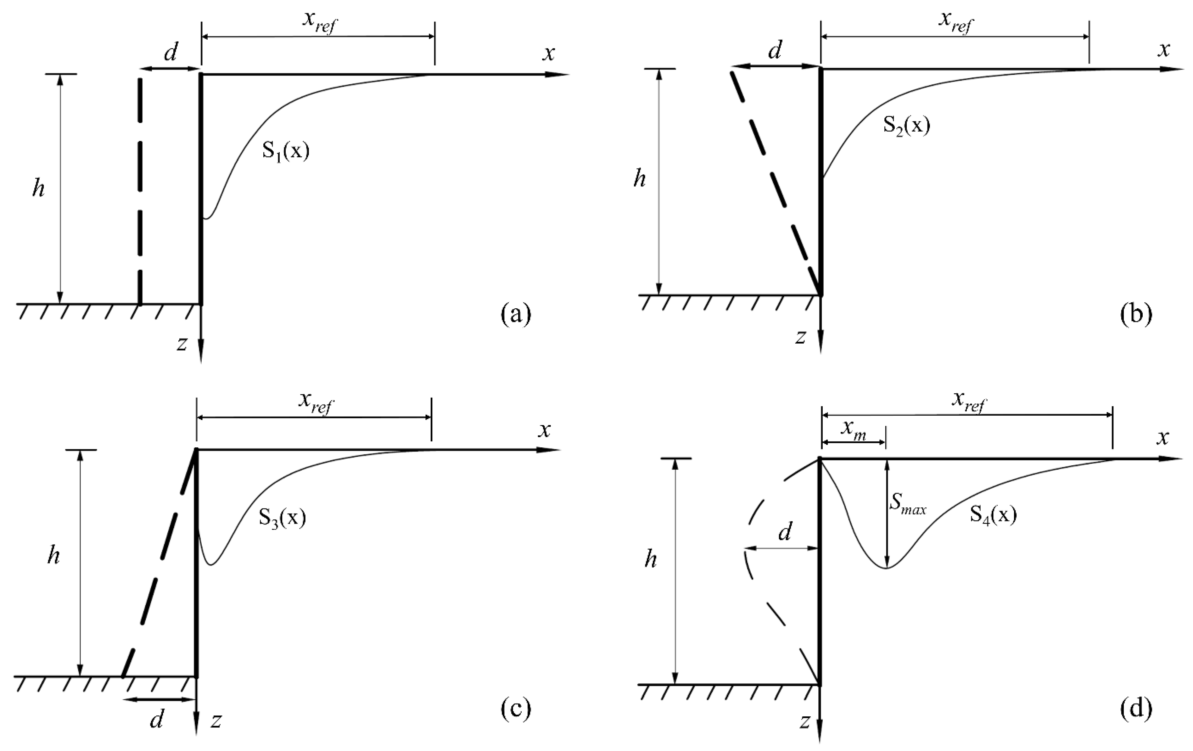
As depicted in Figure 2, the deformation patterns of the retaining wall can be summarized into four typical modes: translation mode, rotation mode around the foot of the wall, rotation mode around the top of the wall, and flexible parabola deformation mode, resulting in different surface settlement patterns, respectively. It should be pointed out that the horizontal deformation of the foundation pit retaining wall is considered as a known displacement boundary, and there is no surcharge load on the surface behind the wall. In addition, it is assumed that the wall back is vertical, the ground behind the wall is horizontal, and the soil behind the wall is homogeneous and isotropic.
The surface settlement formulas under four typical foundation pit deformation conditions are presented below, corresponding to the four equations in Equation (1), respectively. In terms of the equation form involving complex integral transformation, the solution process of the explicit solution is quite complicated to directly obtain the distribution law of the surface settlement curve. In general, assuming that there is a linear relationship between the surface settlement range (i.e., xref) and the foundation pit depth (i.e., h), the surface settlement curves under the maximum horizontal displacement (i.e., d) of different retaining walls are drawn by numerical integration, and the transverse distribution value of the surface settlement would be ultimately obtained by normalization processing.
S 1 ( x ) = 2 h d π 2 + ξ 2 h 2 ( ξ 2 + h 2 ) 2 ln | ξ x ξ x r e f | d ξ S 2 ( x ) = 2 d π 2 + ( h ξ 2 + h 2 + 1 2 h ln ξ 2 ξ 2 + h 2 ) ln | ξ x ξ x r e f | d ξ S 3 ( x ) = 2 d π 2 h + ( 1 4 ln ξ 4 ( ξ 2 + h 2 ) 2 + 2 h 4 ( ξ 2 + h 2 ) 2 ) ln | ξ x ξ x r e f | d ξ S 4 ( x ) = 8 d π 2 h 2 + ( h 2 ln ( ξ 2 ξ 2 + h 2 ) + 3 h + h ξ 2 ξ 2 + h 2 4 ξ arctan ( h ξ ) ) ln | ξ x ξ x r e f | d ξ }
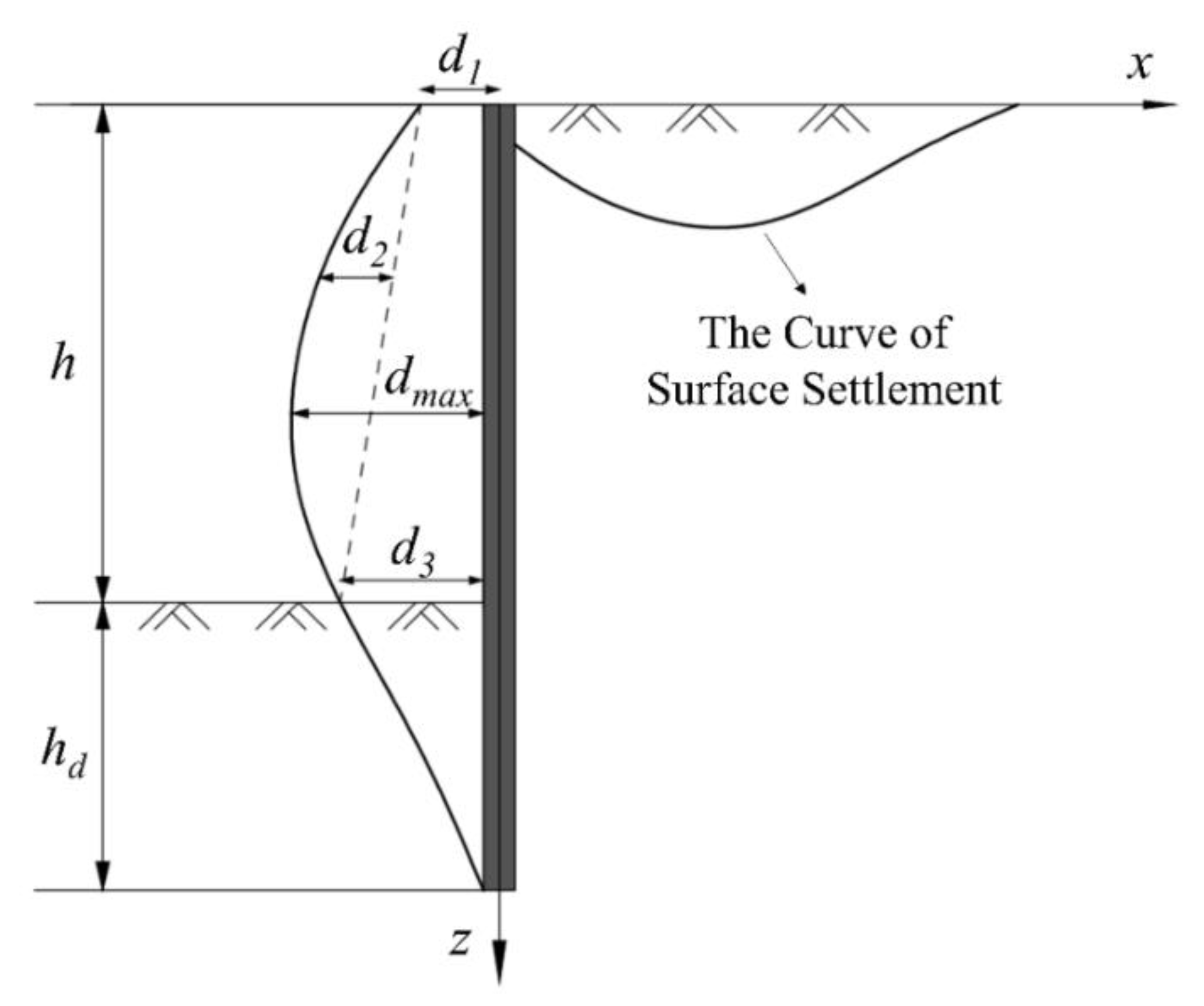
In practical engineering, the deformation of a foundation pit retaining wall is much more complicated than that of the typical four modes. However, as depicted in Figure 3, the horizontal deformation of a general retaining wall can be generally viewed as a superimposition of the above four deformation modes. From the perspective of theoretical calculation, the curve of surface settlement behind the retaining wall can be obtained by fitting several basic settlement curves.
It is observed that in this solving method, there exists much inconvenience in calculation, such as difficulties in accurately analyzing the retaining-wall horizontal deformation curve, cumbersome calculation steps, wide margin of error, etc. However, it can be inspired to regard the retaining-wall lateral deformation as an arbitrary continuous curve, without considering the deformation mode of the foundation pit. The influence of retaining-wall deformation on the surface settlement would be explored from the perspective of differentiation, and specific solutions are elaborated in the next section.

3. Derivation of the Simplified Solution Method

3.1. Solution Thought

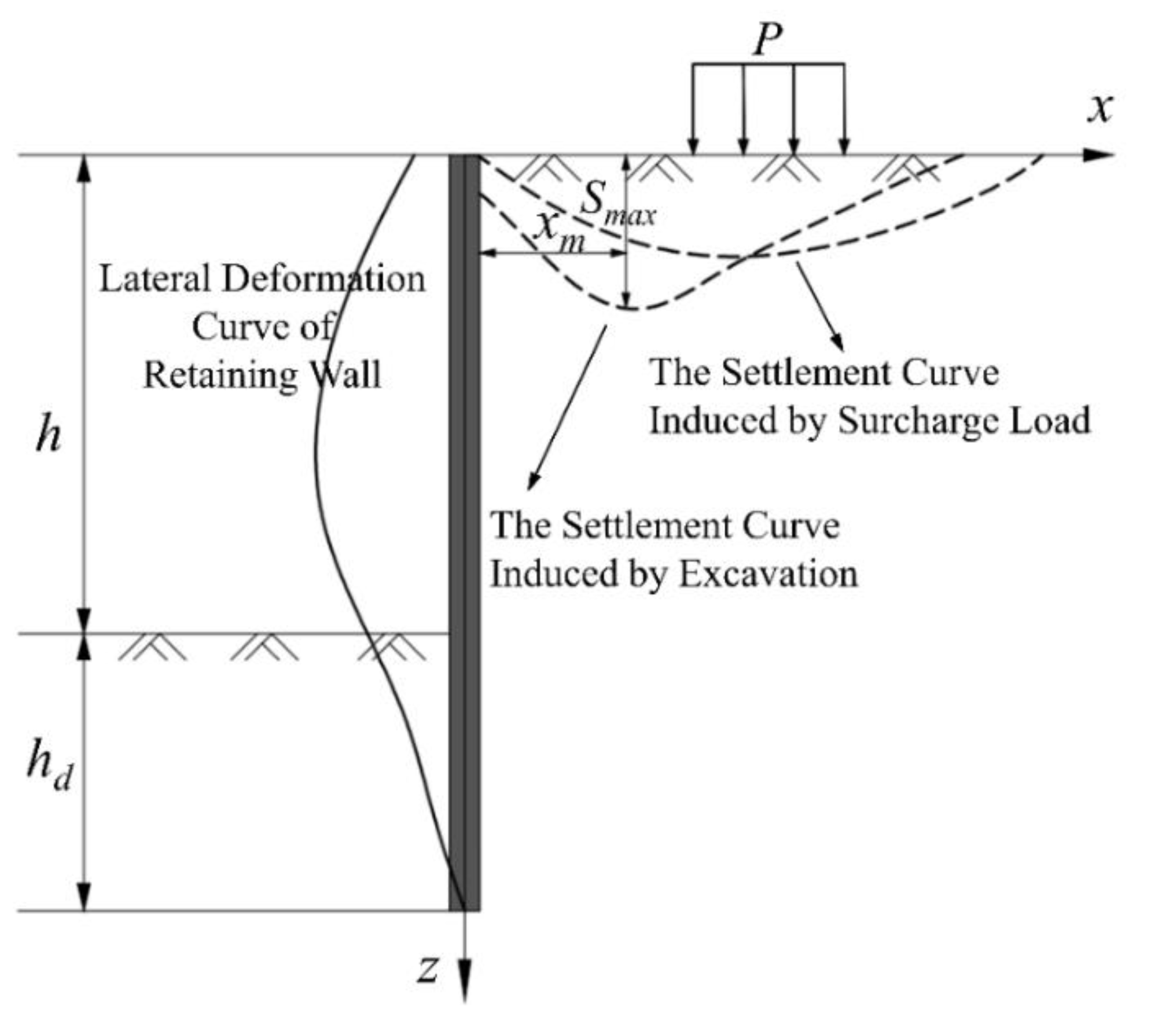
Under the condition of embankment load, the excavation of a foundation pit has more obvious influence on the surrounding surface settlement. In this paper, the influence of foundation pit excavation and bank overloading on the surface settlement is investigated, respectively. As shown in Figure 4, it is assumed that excavation and surface load do not interfere with each other, and there is no coupling effect during the surface settlement.
As a result, the ground surface settlement induced by a deep braced excavation adjacent to a river embankment consists of two parts (Figure 4). The first part is caused by the excavation of the foundation pit itself, and the second part is induced by the embankment surcharge load. In order to estimate and predict the surface settlement around the foundation pit near the embankment, this paper calculates the settlement of the two parts according to the ground loss method and the Boussinesq solution, respectively. The equation for ground settlement can be expressed as
S ( x ) = S Ι ( x ) + S Ι Ι ( x )
where S(x) is the total formula of the ground settlement; SI(x) and SII(x) represent the settlement induced by adjacent excavation and embankment surcharge load, respectively.
According to Nie et al. [26], based on the concept of the formation loss method and a large number of field measurement data, the distribution rule of the surface displacement field around the soft soil deep foundation pit has been deeply investigated, and the surface settlement curve with skewed distribution is proposed as
S I ( x ) = A v 2 π ϖ x exp ( ( ln x 2 x m ) 2 / ( 2 ϖ 2 ) )
where x is expressed as the distance between the calculation point and the edge of the foundation pit; xm represents the distance between maximum settlement point and the edge of foundation pit; and Av is the envelope area of surface settlement curve behind the wall and ω is empirical coefficient (i.e., 0.6–0.7 for a soft soil foundation pit).

3.2. The Influence of Foundation Pit Excavation

In Equation (3), Av and xm are important parameters directly related to the surface settlement curve. However, in many studies and engineering applications in the past, the selection of these two parameters was mostly determined by engineering experience, which may bring out major errors, even resulting in wrong results. Therefore, the determination of Av and xm should be carefully considered, and a simplified method will be performed in the following sections.

3.2.1. Calculation of xm

The ground settlement behind the retaining wall stems from the horizontal movement of the retaining wall in the foundation pit. If the retaining wall is assumed to have rigid translation, the basic analytical solution of the ground settlement induced by the retaining wall under the rigid translation displacement mode can be obtained. Although the possibility of rigid translation of the retaining wall in actual engineering is quite small, the surface subsidence degradation under the complex deformation mode can still be obtained based on the rigid translation mode of retaining wall [29]. Under the boundary condition of the retaining wall rigid translational displacement mode, the first formula in Equation (1) is solved by integration, and the explicit formula can be expressed as
w = 2 d h 2 π ( 1 x 2 + h 2 1 x r e f 2 + h 2 )
where w represents the ground settlement; x is the distance from the foundation pit; and h is the excavation depth.
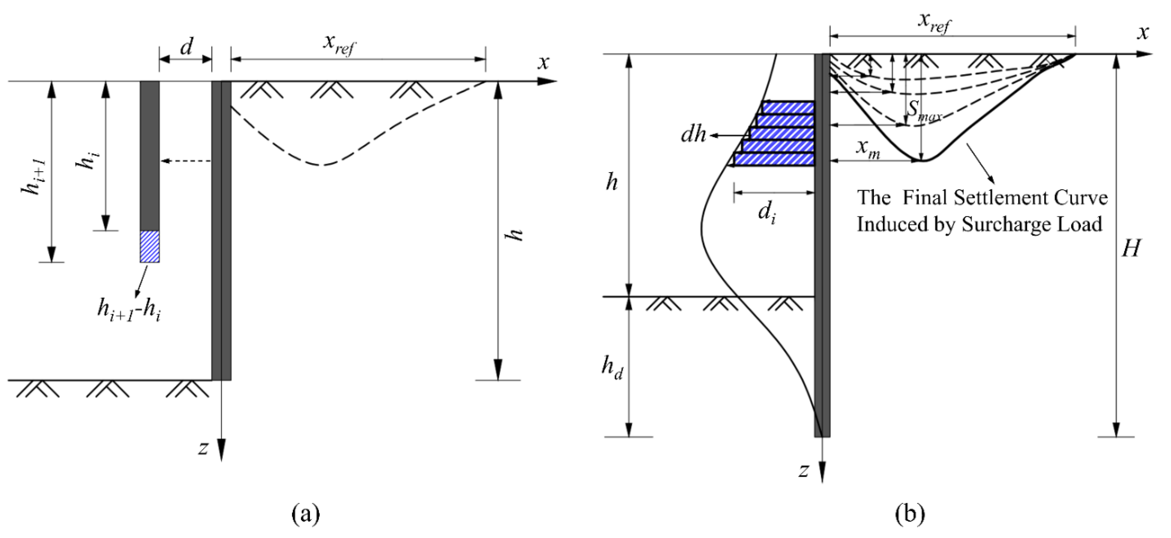
Through the application of the calculus method [30], the horizontal displacement curve of any retaining wall deformation form is divided into an infinite number of micro-segments, and the deformation of each micro-segment is regarded as the rigid translation mode of the retaining wall. According to the surface settlement solution under the retaining wall translational deformation mode, as expressed in Equation (4), the surface settlement caused by each micro-section can be, respectively, calculated. As presented in Figure 5, the surface settlement caused by horizontal deformation of the whole retaining wall would be finally obtained via summation calculation.
The retaining wall can be evenly divided into n segments along the depth direction, and it is assumed that the translation and displacement mode approximately occurred in each small section. For the segment i, the surface settlement value induced under the depth of hi and hi+1 is calculated by Equations (5) and (6), respectively. The relevant equation could be expressed as
w i = 2 d i h i 2 π ( 1 x 2 + h i 2 1 x r e f _ i 2 + h i 2 )
w i + 1 = 2 d i + 1 h i + 1 2 π ( 1 x 2 + h i + 1 2 1 x r e f _ i + 1 2 + h i + 1 2 )
where wi and wi+1 represent the ground settlement induced by segment i and segment i+1, respectively; di and di+1 represent the retaining wall horizontal deformation of segment i and segment i+1, respectively; xref_i and xref_i+1 represent the ground settlement range induced by segment i and segment i+1, respectively.
Based on the superposition principle, making a subtraction between Equations (5) and (6), and the surface settlement ∆wi caused by the translation of any retaining wall segment in the foundation pit is obtained, which can be simplified as
Δ w i = w i + 1 w i = 2 π [ d i + 1 h i + 1 2 ( x r e f _ i + 1 2 x 2 ) ( x 2 + h i + 1 2 ) ( x r e f _ i + 1 2 + h i + 1 2 ) d i h i 2 ( x r e f _ i 2 x 2 ) ( x 2 + h i 2 ) ( x r e f _ i 2 + h i 2 ) ]
Previous studies have indicated that there is a linear relationship between the influence range of surface settlement and the depth of foundation pit excavation. Therefore, for the retaining wall segment in different depths, the influence range of surface settlement caused by their translation can be set as m times of the corresponding depth (i.e., xref_i = mhi, xref_i+1 = mhi+1). Through the substitution of xref_i and xref_i+1 into Equation (7), the final form of ∆wi can be simplified as
Δ w i = 2 π ( m 2 + 1 ) [ d i + 1 ( m 2 h i + 1 2 x 2 ) x 2 + h i + 1 2 d i ( m 2 h i 2 x 2 ) x 2 + h i 2 ]
Ultimately, the surface settlement value Δwi caused by the translation of each micro-section of the retaining wall can be superimposed and summed. As presented in Equation (9), the adjacent surface settlement formula under the horizontal deformation mode of any maintenance structure can be obtained.
w = i = 1 n ( w i + 1 w i ) = i = 1 n Δ w i
Accordingly, xm, the maximum position of surface settlement, can be obtained by w in Equation (9), which is easily realized by programming.

3.2.2. Calculation of Ah

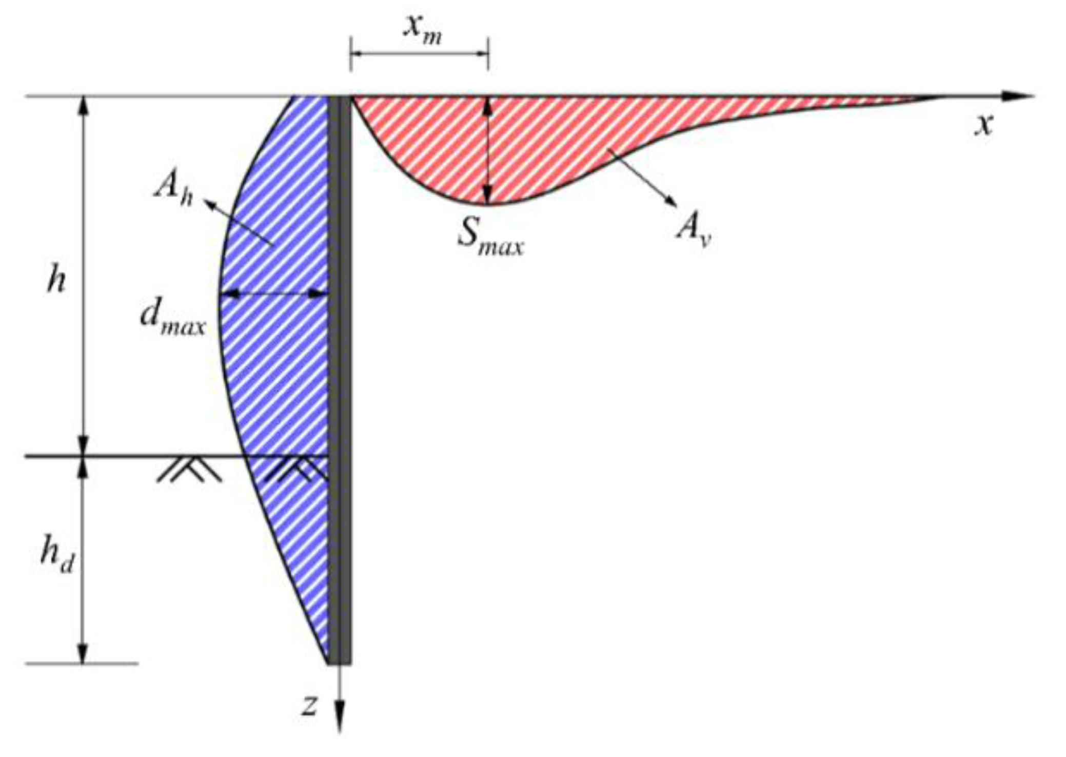
According to a large number of experiments and engineering test data, there is a proportional relationship between the envelope area of the surface settlement curve behind the wall (i.e., Av) and the envelope area of the displacement curve of excavation retaining wall (i.e., Ah) in the soft soil area, which can be expressed as
A v = β A h
where β represents the proportionality coefficient. According to the statistical analysis results and site engineering experience, when the wall penetration ratio hd/h1 (h1 is the final excavation depth, and hd represents the wall embedment depth below the excavation bottom) is less than 0.5, β can be taken as 1.0–1.2; otherwise, it may be within the range of 0.8 to 1.0.
In order to illustrate the expression of Equation (10) more vividly, Figure 6 describes the linear proportionality relation by different colors. The blue diagonal and the red diagonal represent Av and Ah, respectively.
Generally, the horizontal deformation of the supporting structure can be calculated by the elastic fulcrum method or obtained by actual measurement. Before calculating the envelope area of the displacement curve of the supporting structure (i.e., Ah), the displacement data of the calculated or measured points should be processed firstly to make it fit into a continuous smooth curve. In general, any function in a certain section can be approximated by polynomials. Therefore, assuming that the displacement point coordinates of the retaining wall calculated or measured along the depth direction of the foundation pit are (h, d), then the horizontal displacement fitting curve can be expressed as
d ( h ) = i = 0 n a i h i
where n is the order of the polynomial and ai represents the coefficient of the independent variable in the polynomial.
According to Nie and Hu’s research [26,29], the lateral displacement value of supporting structure can be approximated by a quadratic parabolic function. Taking the first three terms of Equation (11), d(h) can be expressed as
d ( h ) = a 0 + a 1 h + a 2 h 2
Based on the least square method, the equation set can be obtained as
a 0 n + a 1 i = 1 n h i + a 2 i = 1 n h i 2 = i = 1 n d i a 0 i = 1 n h i + a 1 i = 1 n h i 2 + a 2 i = 1 n h i 3 = i = 1 n h i d i a 0 i = 1 n h i 2 + a 1 i = 1 n h i 3 + a 2 i = 1 n h i 4 = i = 1 n h i 2 d i }
where hi and di represent the depth of the retaining wall and the corresponding horizontal displacement values acquired by calculating or measuring, respectively.
Substituting the known hi and di into Equation (13), the values of the coefficients a0, a1 and a2 would be obtained. According to the vertex coordinates (0, a0) and extreme points (hm, dm) of the supporting structure, a1 and a2 can be finally derived as
a 1 = 2 ( a 0 d m ) h m a 2 = a 0 d m h m 2 }
By integral calculation of Equation (12), the area enclosed by the horizontal displacement curve of the supporting structure can be expressed as
A h = 0 H ( a 0 + a 1 h + a 2 h 2 ) d h = a 0 H + 1 2 a 1 H 2 + 1 3 a 2 H 3
where H is the entire height of the retaining wall.
Substituting Equations (10) and (15) into Equation (3) yields
S I ( x ) = β A h 2 π ϖ x exp ( ( ln x 2 x m ) 2 / ( 2 ϖ 2 ) )

3.3. The Influence of Embankment Surcharge Load

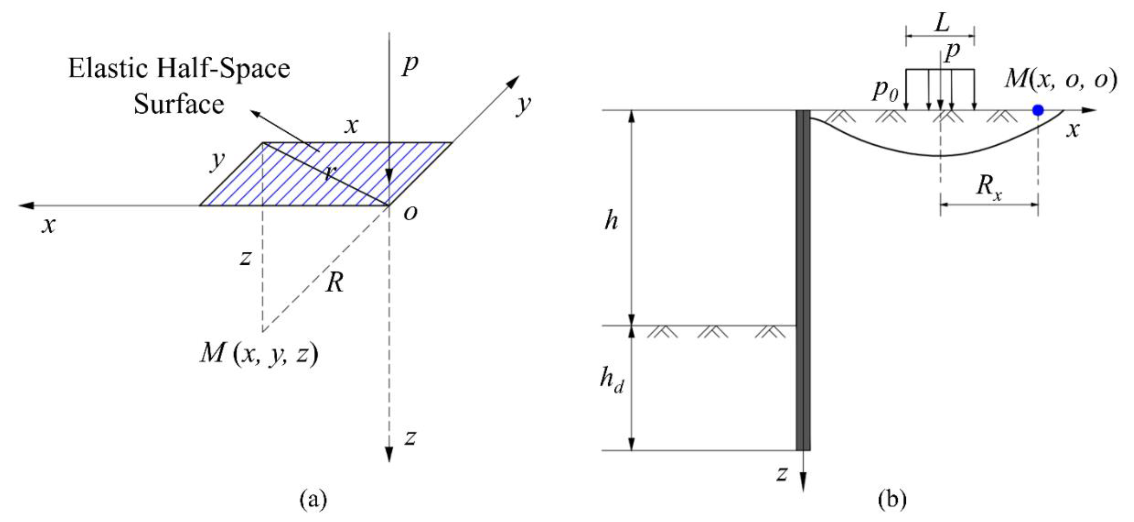
For the influence of the embankment load, the uniformly distributed load is simplified as a vertical concentrated force. Therefore, the embankment pavement settlement curve under the condition of foundation pit excavation can be obtained by the Boussinesq solution in semi-infinite space.
As depicted in Figure 7a, for an any point M (x, y, z) in the elastic half space, Boussinesq has derived the calculation formulas induced by the vertical concentrated load P acted on the surface. According to Boussinesq solution, vertical deformation (i.e., u(z)) can be expressed in the form of
u ( z ) = p ( 1 + μ ) 2 π E [ z 2 R 3 + 2 ( 1 μ ) 1 R ]
where R is the distance from target calculation point to load point; μ is Poisson’s ratio; and E is the elasticity modulus.
When taking the embankment surcharge load into consideration, as depicted in Figure 7b, the embankment surcharge load is simplified as the vertical concentrated load perpendicular to the embankment surface, and the settlement at any point behind the wall can be figured out via Boussinesq solution.
For the condition of surface settlement, the value of z is 0. Similarly, R can be simplified as the horizontal distance between the target surface point and the equivalent concentrated force operation point, which is expressed with Rx. By assigning z to 0 in Equation (17), the expression for u (z) can be simplified to
u ( z ) = p ( 1 μ 2 ) π E R x
In this paper, a three-dimensional foundation pit is analyzed as a plane strain problem. Accordingly, the embankment load is considered approximately as a uniform load with width L on the section. Therefore, the concentrated force P can be replaced by p0L through integration, and u(z) can be finally derived as
u ( z ) = p 0 L ( 1 μ 2 ) π E R x
The settlement value of any point on the surface induced by the embankment load can be obtained by Equation (19), and the settlement value of other points can also be obtained by this method. Therefore, the settlement values at different locations on the surface are selected at equal intervals, and the complete settlement curve caused by the embankment surcharge load can be obtained through curve fitting (i.e., SII (x)).

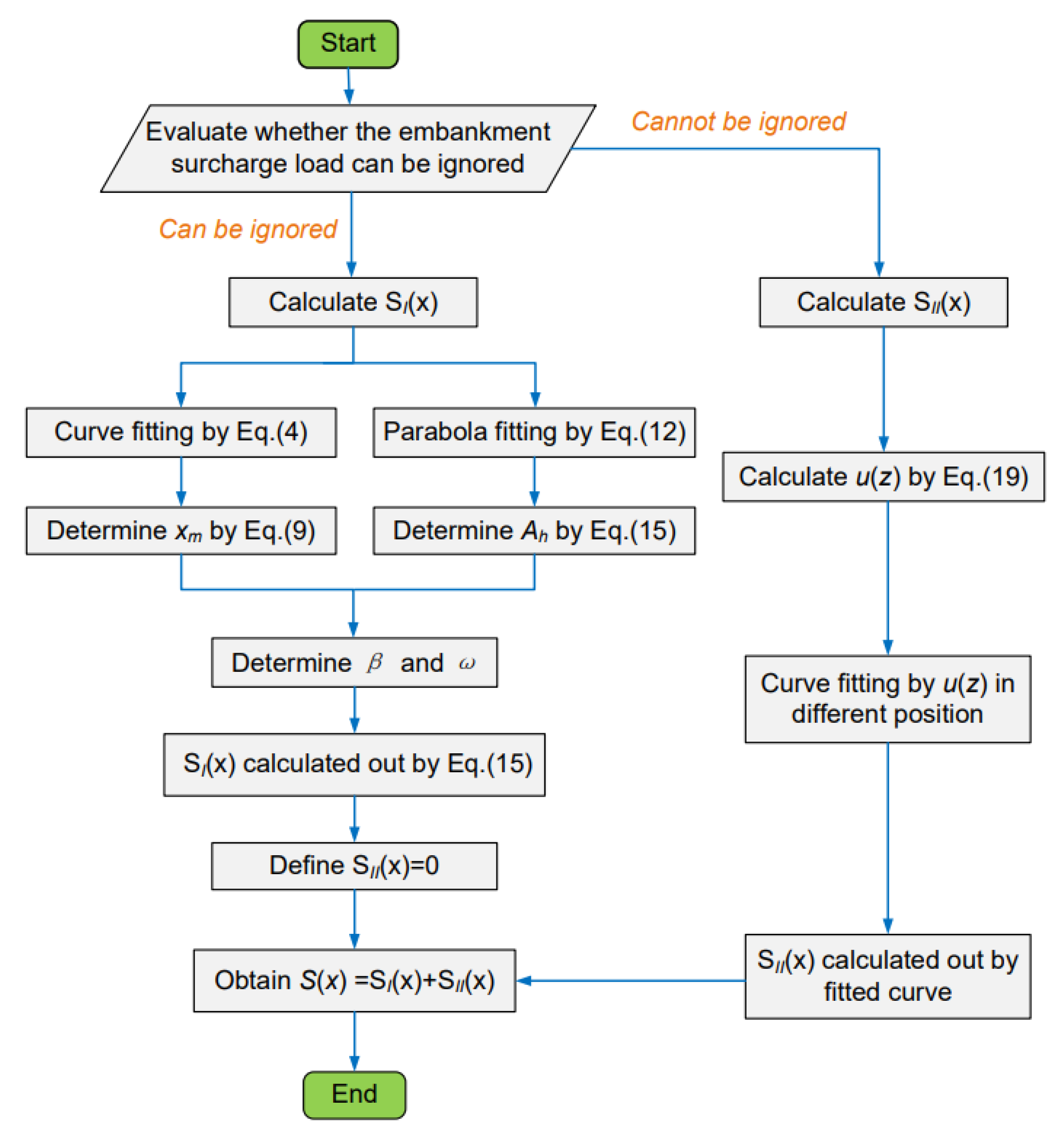
3.4. Optimized Solution Procedure

To clearly demonstrate the whole derivation process of the proposed analytical method, a flow chart is helpful, which is presented in Figure 8.

4. Validation of the Simplified Analytical Method through Case Histories

In order to verify the applicability and accuracy of the simplified prediction formula in this paper, some specific engineering cases should be combined to meticulously analyze and illustrate. Case 1 and Case 2 are real projects involved in relevant sources from the literature [25,26]. The observation deformation data of the foundation pit supporting structure and the surface settlement caused by it were well recorded, which could well compare the advantages and disadvantages of the proposed method with the previous methods. Case 3 is an engineering project that the authors participated in personally. It mainly considers the influence of foundation pit excavation on surface deformation under the presence of embankment load, which is deserves special attention.

4.1. Case History 1

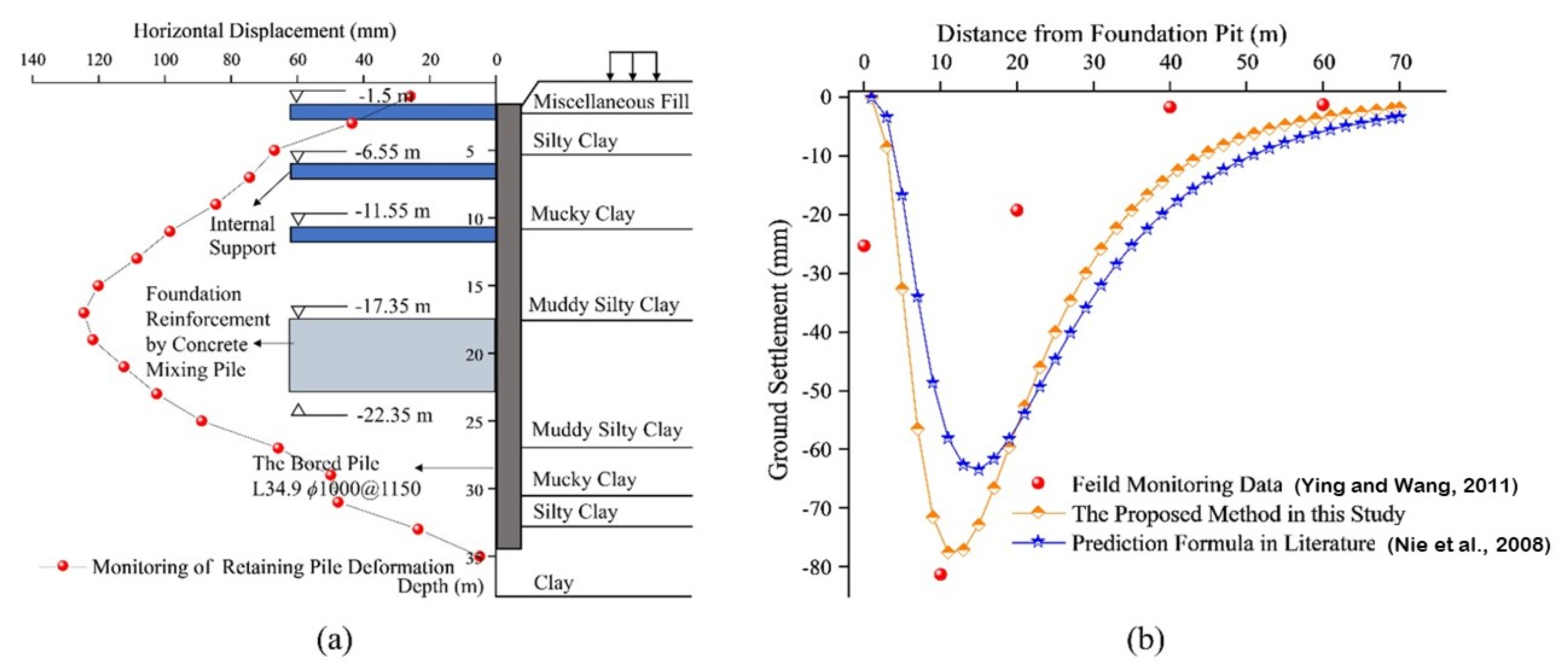
The underground part of a commercial and residential building in Hangzhou is a three-floor basement [25]. The project site is the alluvial plain landform of Qiantang River, with relatively flat terrain. The area affected by the excavation depth is dominated by saturated soft soil such as deep muddy clay, and the groundwater level is stable at about 1.5 m below the surface. The depth of this deep excavation pit varied between 14.85 and 17.35 m, and the bored pile walls with the size of 1.0 m × 38.0 m × 0.15 m (diameter × length × spacing) were installed to brace this deep excavation. Three levels of reinforced concrete struts were encountered for the most part of the excavation, while four levels of them were applied for local part where the excavation depth reached 17.35 m. In the foundation pit, triaxial cement mixing piles were used to strengthen the soil in the passive area. The width of the reinforcement strip varied from 7.2 m to 13.7 m according to the importance of the surrounding environment.
To validate the simplified analytical method proposed in this paper, the middle part of the west side of the foundation pit (i.e., CX2 section) was selected for research. For this part, the depth of the excavation was h = 17.35 m, and the reinforcement depth of mixing pile was 5 m. It should be noted that a six-story pile foundation building was located 20 m to the west of the retaining wall. As clearly presented in Figure 9a, the observed pile top displacement (i.e., d1) at the CX2 section equals 25.9 mm, and the observed excavation basal displacement (i.e., d3) equals 124.5 mm. In this project, the displacement at the bottom of pit is the maximum displacement of retaining pile. It is a common way to predict the ground settlement around the foundation pit based on the calculated or measured displacement data of the retaining wall. The observed surface settlement data, the prediction formula in the literature [26], and proposed method in this paper are compared, and the surface settlement curves are, respectively, depicted in Figure 9b. According to the correlation between the influence degree and the influence scope of the foundation pit excavation, five observation points were set, respectively, located at 0 m, 5 m, 10 m, 20 m and 40 m from the edge of the foundation pit.
Table 1 presents parameter values and corresponding ground settlement results for several methods. In the approach proposed in this paper, Equation (9) can be applied for fitting, which yields the maximum settlement location xm = 11 m. By utilizing numerical integration method, the envelope area of the retaining structure lateral deformation curve can be obtained: Ah = 2314.5 m·mm, where β = 0.9, and ω = 0.65 according to experience. In the prediction formula [26], xm is defined as a parameter linearly related to the foundation pit depth based on engineering experience and geology conditions, and xm is set as 12.1 m in Case History 1, which equals to the excavation depth of 0.7 times. In addition, other parameters are consistent with the formula in this paper. The surface settlement curve can be obtained by substituting all parameters into Equations (15) and (16). As presented in Figure 9b, the method proposed in this paper performs well in approaching the observed results. Compared with the original settlement prediction formula, the simplified method used in this study is more accurate in fitting with the field monitoring values, especially the maximum settlement value, demonstrating the effectiveness of the proposed analytical method in this paper.

4.2. Case History 2

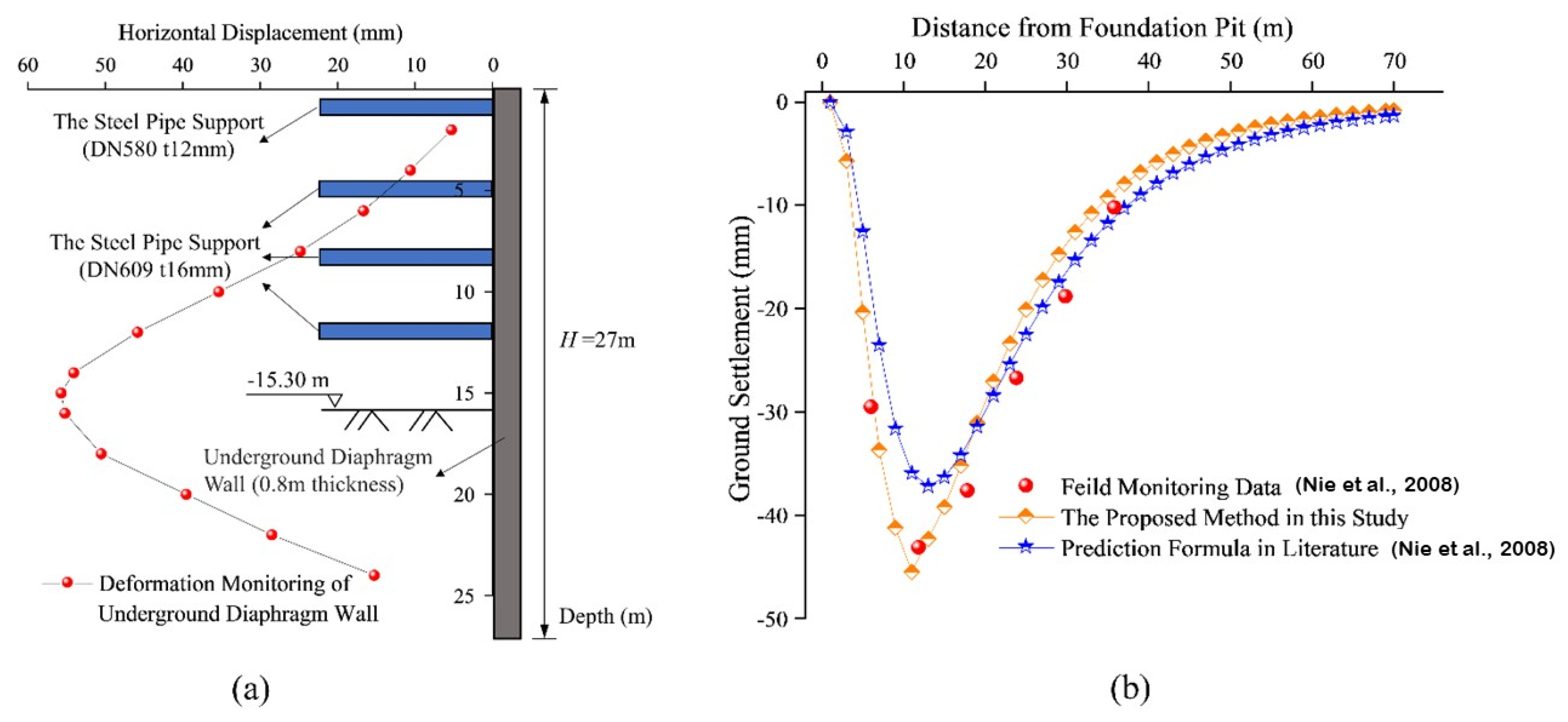
This case history is the Shanghai Metro Line M8 Yanji Middle Road Station, located in the Yangpu District, Shanghai, China [26]. In this project, the diaphragm wall with 0.8 m in thickness, 27 m in length, and 0.76 m in penetration ratio, was constructed to serve as not only the bracing structure, but also the main structure side wall used during the in-service phase. The depth of the excavation in the standard segment adjacent to the monitoring point C28-1 was 15.3 m (i.e., h) and four levels of steel pipe struts were constructed along the depth direction. The observed horizontal wall displacement at the wall top was d1 = 0.14 mm. The maximum horizontal wall displacement occurred approximately at the excavation bottom, with a magnitude of d2 = 55.71 mm. As depicted in Figure 10a, the displacement at the top of the wall was quite small, and the maximum horizontal displacement was located at the bottom of the foundation pit.
Table 2 presents some key parameter settings and ground settlement results from field monitoring [26], prediction formula in the literature [26], and proposed method in this study. It is noted that the values of Ah and Av are relatively close in the observed data, which is quite different from the conventional prediction formula. This may be caused by the vehicle dynamic load and material surcharge in the site. Due to the lack of available reference data, other parameters are obtained according to the literature [26]: Ah = 1083.8 m·mm, β = 0.9, and w = 0.65. Moreover, the prediction formula proposed in this paper also draws on some parameters in the literature above, such as β and w, which improve the accuracy of surface subsidence results.
A multiple comparison of the ground surface settlements for this case history has been performed using two different analytical methods, and relevant data are depicted in Figure 10b. It can be indicated that, in Case History 2, the calculated results of the prediction formula proposed in this paper are in good agreement with the measured data, and the fitting result is more accurate than the method in the literature. Specifically, the observed Av was 876.3 m·mm, while the method in the reference [26] predicted a value of 759.9 m·mm, with an error of 15.4%. This also causes the Vm of this method to differ significantly from the actual observed value, at 13.7%. In the method presented in this paper, Av and Vm have relatively small deviations from the field-measured values, which are 5.0% and 5.6%, respectively. Further investigation indicates that xm, a parameter closely related to surface settlement, was determined by engineering experience in the literature [26], whereas it was obtained by integral fitting in this paper. It is obvious that the prediction formula for the surface displacement field with skewed distribution behind the wall proposed in literature [26] is relatively simple. Up till now, most values of some parameters in the formula are obtained by engineering experience, which would increase the uncertainty of the prediction formula. In the proposed analytical method, the values of xm and Ah are optimized to make the values of parameters more reasonable and the prediction results of surface settlement more accurate.

4.3. Case History 3

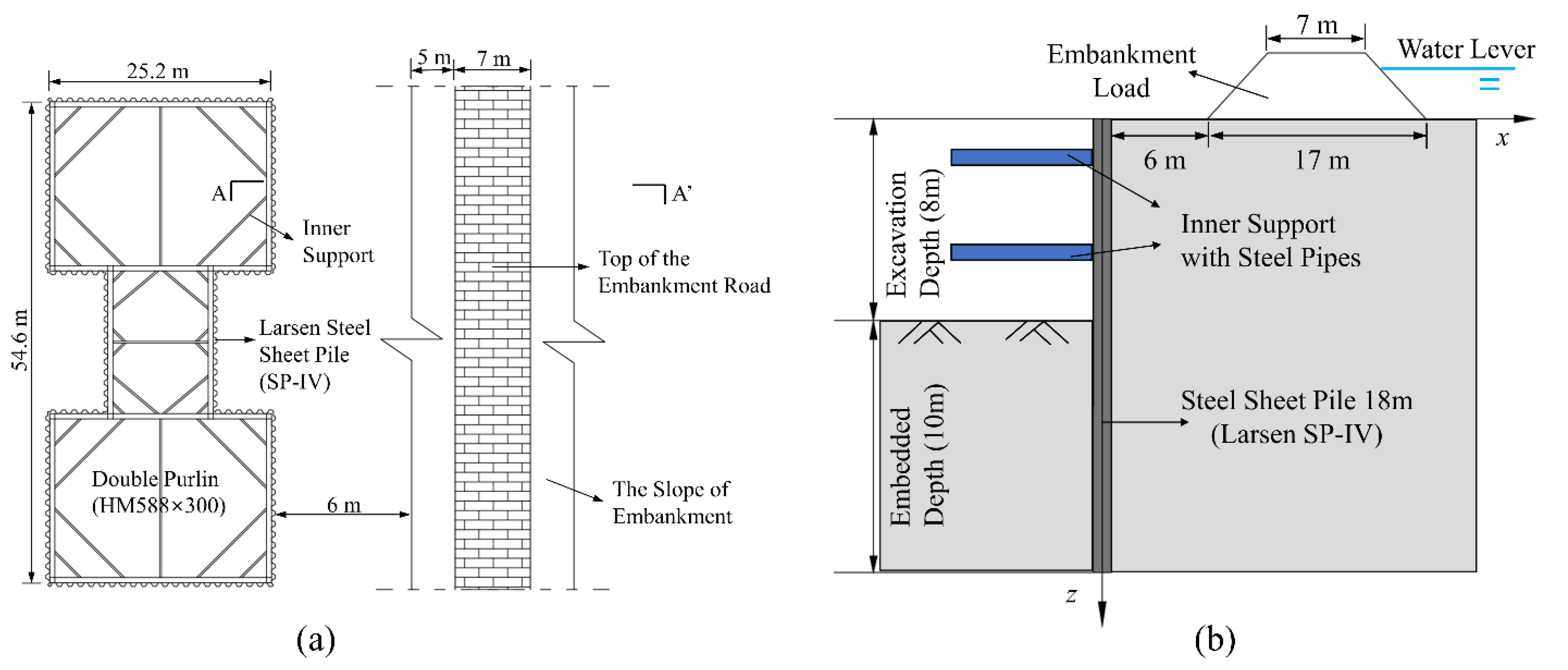
This case is based on a deep foundation pit project for the construction of bridge pile foundations, located in Anqing, Anhui Province, China. The length of the main structural part of Yangwanhe Bridge is 685 m, of which the 14 # main pier is located outside the Tongma Causeway of Yangwan River on the land. The cushion cap foundation pit is supported by cofferdam method, and the single row Larsen steel sheet pile (SP-IV. PU600 × 210) was selected as the maintenance structure. The steel sheet pile foundation pit is symmetrical dumbbell type, with length of 54.6 m, width of 25.2 m and height of 18 m. It is internally supported by two enclosing purlins, and the excavation depth is 8 m. Figure 11a describes the position relationship between the steel cofferdam and the embankment on the plane, and the horizontal distance between them is 6 m.
A typical steel cofferdam profile (A-A′) in Figure 11a is selected and depicted in Figure 11b. In view of the distance between the foundation pit and the bank embankment is only 6 m, the settlement deformation of the bank embankment pavement deserves attention. The profile of the bank embankment is a symmetrical trapezoid, with a pavement width of 7 m, a height of 5 m and a slope of 45°. Yangwan River is on the other side of the embankment, and the water level is relatively stable throughout the year. According to the engineering geological survey report, the stratum around the foundation pit is mainly cohesive soil.
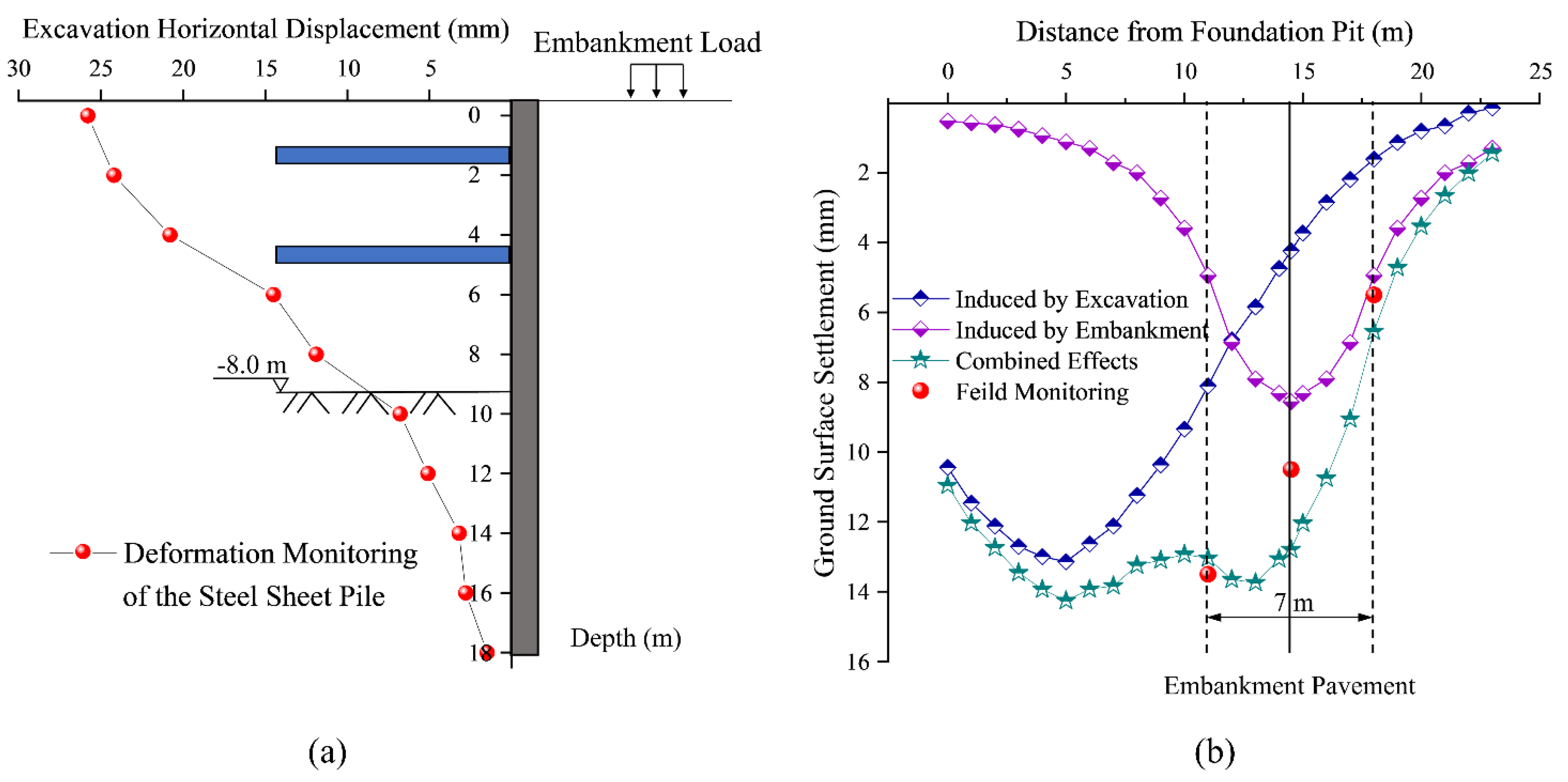
As depicted in Figure 12a, during the construction process, the maximum lateral deformation of steel sheet pile cofferdam, with the value of 25.8 mm, is at the top of pile, and the maximum deformation value at the bottom of foundation pit is 9.3 mm, both of which are within a reasonable deformation range. The area of the envelope formed by the sheet pile lateral movement (i.e., Ah) is 216.3 m·mm, and the empirical coefficient of the settlement envelope (i.e., β) is determined with 0.9 based on previous engineering experience. Therefore, the area of the surface settlement envelope curve (i.e., Av) outside the foundation pit is 194.7 m·mm. The value of xm can be obtained by superposition fitting of the micro-segment settlement curve calculated by Equation (8). In case history 3, the maximum settlement point calculated is 4.9 m away from the foundation pit. In addition, ω refers to the value of 0.65 in the reference [26]. By taking the above parameters into Equation (15) for calculation, the influence of foundation pit excavation on the surface settlement can be obtained. Furthermore, the influence of bank overloading can be easily obtained by the Boussinesq solution. Considering that the deformation of embankment pavement is the focus of attention, settlement observation points were set in the middle and both sides of the road.
Figure 12b presents the characteristic curve of surface settlement under the combined action of bank overload and foundation pit excavation. The predicted maximum settlement value of the embankment pavement coincides with the measured value very well, which strongly proves the effectiveness of this proposed method in predicting and evaluating the ground settlement induced by foundation pit excavation under the condition of existing embankment surcharge load.

5. Conclusions

In the method proposed in this paper, the ground settlement induced by foundation pit excavation and embankment surcharge load is determined using the modified skewness prediction formula and the simplified Boussinesq solution, respectively, and it is assumed that no coupling effect exists between the two settlement sources. Compared with the observed values, the error of the maximum settlement point and the corresponding maximum settlement value calculated by the method in this paper is almost controlled within 5%, of which the accuracy is much higher than the existing prediction formula.
  • The ground overloading such as embankment overload has a certain influence on the surface settlement during the foundation pit excavation, which should be paid more attention to in the project. In this paper, the Boussinesq solution is applied to simplify the embankment load into the vertical concentrated force, and the ground settlement curve is easily calculated and fitted, which can well take into account the impact of ground overload.
  • As for the surrounding surface settlement caused by foundation pit excavation, the value of xm is generally determined by engineering experience in the previous partial settlement prediction formula, which is an important factor leading to a large deviation between the measured value and the theoretical prediction value. This paper improves the determination of xm by the method of combining calculus with curve fitting, and the predicted value obtained by this method comes close to the measured one. Accordingly, in the three cases, the deviation between the calculated value of vm and the actual observation value is 4.6%, 5.5% and 3.4%, respectively.
  • Based on the classic prediction formula of surface subsidence skewness distribution, the simplified method in this paper draws on some empirical parameters, such as β and ω, which are derived from many engineering practices and have proved reliability among projects. However, the value range of these parameters is quite wide, and bring out many difficulties to determine the most reasonable parameter value in settlement prediction. As a result, it is necessary to make a more detailed division for the value range of empirical parameters in subsequent studies.
In conclusion, this simplified calculation method can significantly bring down the reliability and uncertainty of ground settlement prediction around the foundation pit. It is worth noting that although the accuracy of this method is demonstrated through the existing deformation data of the foundation pit retaining wall structure in the cases, the lateral displacement of the retaining wall can also be preliminarily determined via numerical simulation or theoretical formula calculation in engineering applications, and the ground settlement outside the foundation pit can be further derived.

Author Contributions

Conceptualization, Y.W. and S.C.; methodology J.O.; software, J.L.; validation, P.G.; investigation, Y.Z. and H.L. All authors have read and agreed to the published version of the manuscript.

Funding

This research work was funded by the National Natural Science Foundation of China (42077249, 51774107), the Opening Project of State Key Laboratory of Explosion Science and Technology, Beijing Institute of Technology (KFJJ21-03Z).

Institutional Review Board Statement

Not applicable.

Informed Consent Statement

Not applicable.

Data Availability Statement

The data support the findings of this study are not publicly available due to privacy.

Conflicts of Interest

The authors declare no conflict of interest.

References

  1. Jiang, H.; Zhu, J.C.; Zhang, X.Y.; Zhang, J.X.; Li, H.L.; Meng, L.F. Wear Mechanism and Life Prediction of the Ripper in a 9-m-diameter Shield Machine Tunneling Project of the Beijing New Airport Line in a Sand-pebble Stratum. Deep Undergr. Sci. Eng. 2022, 1, 65–76. [Google Scholar] [CrossRef]
  2. Guo, P.P.; Gong, X.N.; Wang, Y.X.; Lin, H.; Zhao, Y.L. Minimum Cover Depth Estimation for Underwater Shield Tunnels. Tunn. Undergr. Space Technol. 2021, 115, 104027. [Google Scholar] [CrossRef]
  3. Ong, D.E.L.; Jong, S.C.; Cheng, W.C. Ground and Groundwater Responses Due to Shaft Excavation in Organic Soils. J. Geotech. Geoenviron. 2022, 148, 05022003. [Google Scholar] [CrossRef]
  4. Peck, R.B. Deep Excavations and Tunneling in Soft Ground. In Proceedings of the 7th International Conference on Soil Mechanics and Foundation Engineering (Mexico), Mexico City, Mexico, 29 August 1969; pp. 225–290. [Google Scholar]
  5. Hsieh, P.G.; Ou, C.Y. Shape of Ground Surface Settlement Profiles Caused by Excavation. Can. Geotech. J. 1998, 35, 1004–1017. [Google Scholar] [CrossRef]
  6. Wang, J.H.; Xu, Z.H.; Wang, W.D. Wall and Ground Movements Due to Deep Excavations in Shanghai Soft Soils. J. Geotech. Geoenviron. Eng. 2010, 136, 985–994. [Google Scholar] [CrossRef]
  7. Qian, J.G.; Tong, Y.M.; Mu, L.L.; Lu, Q.; Zhao, H.Q. A Displacement Controlled Method for Evaluating Ground Settlement Induced by Excavation in Clay. Geomech. Eng. 2020, 20, 275–285. [Google Scholar] [CrossRef]
  8. Ou, C.Y.; Teng, F.C.; Li, C.W. A Simplified Estimation of Excavation-Induced Ground Movements for Adjacent Building Damage Potential Assessment. Tunn. Undergr. Space Technol. 2020, 106, 103561. [Google Scholar] [CrossRef]
  9. Benson Hsiung, B.C. Observations of the Ground and Structural Behaviours Induced by a Deep Excavation in Loose Sands. Acta Geotech. 2020, 15, 1577–1593. [Google Scholar] [CrossRef]
  10. Li, M.G.; Demeijer, O.; Chen, J.J. Effectiveness of Servo Struts in Controlling Excavation-Induced Wall Deflection and Ground Settlement. Acta Geotech. 2020, 15, 2575–2590. [Google Scholar] [CrossRef]
  11. Ni, X.D.; Lu, J.F.; Wang, Y.; Shi, J.W.; Chen, W.C.; Tang, L.X. Field Investigation of the Influence of Basement Excavation and Dewatering on Ground and Structure Responses. Tunn. Undergr. Space Technol. 2021, 117, 104121. [Google Scholar] [CrossRef]
  12. Mohammad Shoari Shoar, S.; Heshmati, A.A.; Salehzadeh, H. Prefailure Deformation of Nailed Deep Excavations under Surcharge by Centrifuge Model Test. Adv. Civ. Eng. 2021, 2021, 5569797. [Google Scholar] [CrossRef]
  13. Zeng, C.F.; Song, W.W.; Xue, X.L.; Li, M.K.; Bai, N.; Mei, G.X. Construction Dewatering in a Metro Station Incorporating Buttress Retaining Wall to Limit Ground Settlement: Insights from Experimental Modelling. Tunn. Undergr. Space Technol. 2021, 116, 104124. [Google Scholar] [CrossRef]
  14. Xiang, P.F.; Wei, G.; Zhang, S.M.; Cui, Y.L.; Guo, H.F. Model Test on the Influence of Surcharge, Unloading and Excavation of Soft Clay Soils on Shield Tunnels. Symmetry 2021, 13, 2020. [Google Scholar] [CrossRef]
  15. Pal, A.; Roser, J.; Vulic, M. Surface Subsidence Prognosis above an Underground Longwall Excavation and Based on 3D Point Cloud Analysis. Minerals 2020, 10, 82. [Google Scholar] [CrossRef] [Green Version]
  16. Ying, H.W.; Cheng, K.; Liu, S.J.; Xu, R.Q.; Lin, C.G.; Zhu, C.W.; Gan, X.L. An Efficient Method for Evaluating the Ground Surface Settlement of Hangzhou Metro Deep Basement Considering the Excavation Process. Acta Geotech. 2022, 17, 5759–5771. [Google Scholar] [CrossRef]
  17. Ou, C.Y.; Hsieh, P.G. A Simplified Method for Predicting Ground Settlement Profiles Induced by Excavation in Soft Clay. Comput. Geotech. 2011, 38, 987–997. [Google Scholar] [CrossRef]
  18. Hu, Z.F.; Chen, J.; Deng, Y.L.; Li, J.B. A Simplified Method for Predicting Ground Surface Settlement Induced by Deep Excavation of Clay Stratum. J. Yangtze River Sci. Res. Instig. 2019, 36, 60–67+72. [Google Scholar]
  19. Guo, P.P.; Gong, X.N.; Wang, Y.X. Displacement and Force Analyses of Braced Structure of Deep Excavation Considering Unsymmetrical Surcharge Effect. Comput. Geotech. 2019, 113, 103102. [Google Scholar] [CrossRef]
  20. Rashidi, F.; Shahir, H. Numerical Investigation of Anchored Soldier Pile Wall Performance in the Presence of Surcharge. Int. J. Geotech. Eng. 2019, 13, 162–171. [Google Scholar] [CrossRef]
  21. Xu, C.J.; Yin, M.; Lin, G. Characters Analysis of the Retaining Structure of the Foundation Pit under Local Load. Appl. Mech. Mat. 2014, 477–478, 448–452. [Google Scholar] [CrossRef]
  22. Li, X.; Zhou, T.G.; Wang, Y.X.; Han, J.L.; Wang, Y.Q.; Tong, F.; Li, D.L.; Wen, J.M. Response Analysis of Deep Foundation Excavation and Dewatering on Surface Settlements. Adv. Civ. Eng. 2020, 2020, 8855839. [Google Scholar] [CrossRef]
  23. Zhang, X.; Wang, L.H.; Wang, H.L.; Feng, C.L.; Shi, H.J.; Wu, S.Z. Investigating Impacts of Deep Foundation Pit Dewatering on Land Subsidence Based on CFD-DEM Method. Eur. J. Environ. Civ. Eng. 2022, 26, 6424–6443. [Google Scholar] [CrossRef]
  24. Zheng, G.; Li, Q.H.; Cheng, X.S.; Ha, D.; Shi, J.C.; Shi, X.R.; Lei, Y.W. Diaphragm Wall Deformation and Ground Settlement Caused by Dewatering before Excavation in Strata with Leaky Aquifers. Geotechnique 2022. [Google Scholar] [CrossRef]
  25. Ying, H.W.; Yang, Y.W. Characteristics of A Large and Deep Soft Clay Excavation in Hangzhou. Chin. J. Geotech. Eng. 2011, 33, 1838–1846. [Google Scholar]
  26. Nie, Z.Q.; Zhang, S.G.; Meng, S.P. Surface Settlement of Deep Foundation Pits by Excavation. Chin. J. Geotech. Eng. 2008, 30, 1218–1223. [Google Scholar]
  27. Qian, J.G.; Wang, W.Q. Analytical Solutions to Ground Settlement Induced by Movement of Rigid Retaining Wall. Chin. J. Rock Mech. Eng. 2013, 32, 2698–2703. [Google Scholar]
  28. Gu, J.B.; Qian, J.G. Analytical Theory of Ground Settlement Induced by Movement of Flexible Retaining Wall. Chin. Rock Soil Mech. 2015, 36, 465–470. [Google Scholar] [CrossRef]
  29. Hu, Z.F.; Chen, J.; Deng, Y.F.; Li, J.B.; Zhou, X.T. Explicit Analytical Solution of Surface Settlement Induced by Horizontal Displacement of Retaining Wall. Rock Soil Mech. 2018, 39, 4165–4175. [Google Scholar] [CrossRef]
  30. Shen, L.Y.; Qian, J.G.; Zhang, R.Z. Simplified Analytical Solution of Ground Settlement Induced by Horizontal Displacement of Retaining Wall. Rock Soil Mech. 2016, 37, 2293–2298. [Google Scholar] [CrossRef]
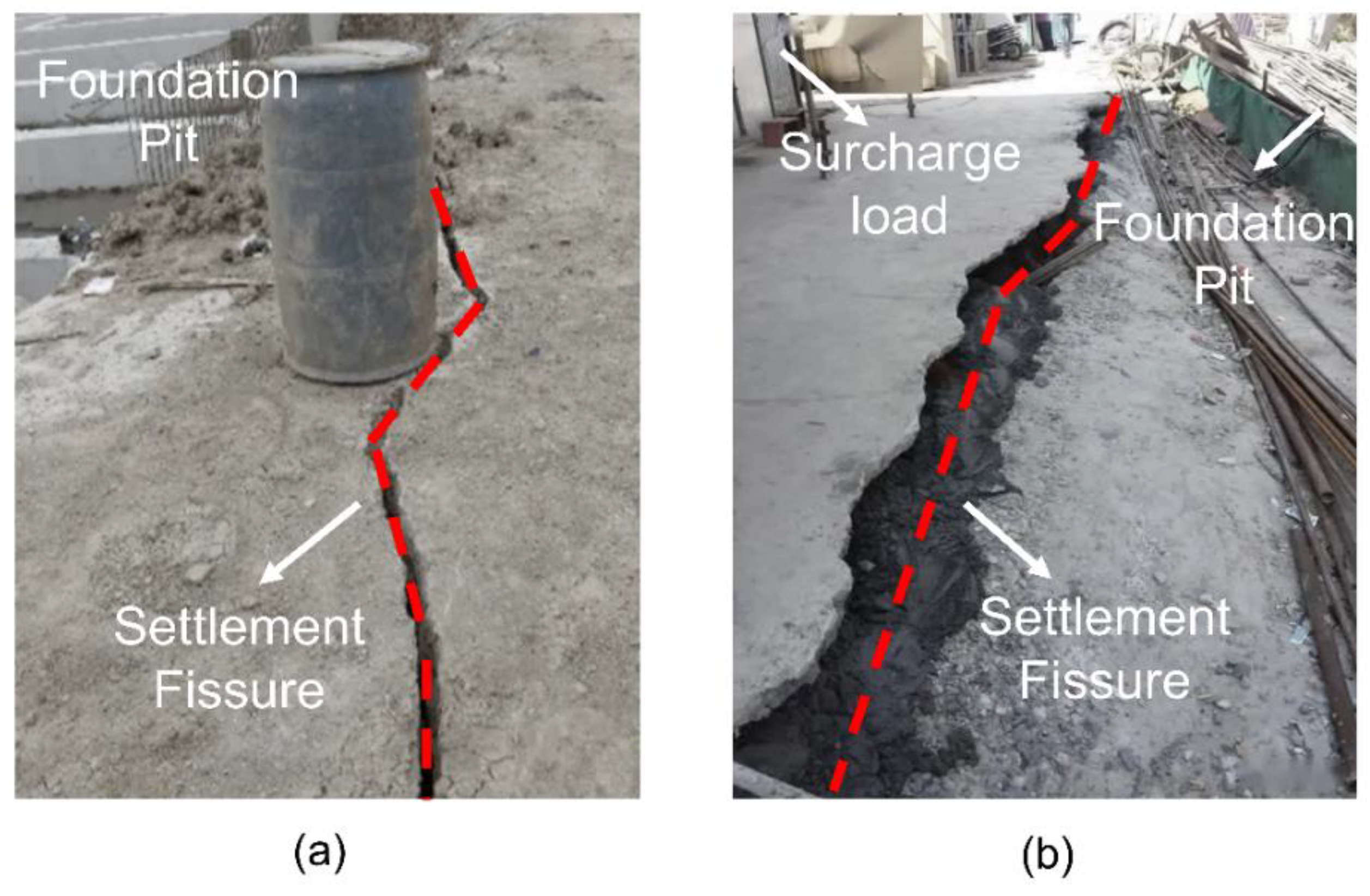
Figure 1. Settlement fissure induced by deep excavation: (a) condition without surcharge load; (b) condition under surcharge load.
Water 14 03868 g001
Figure 2. Typical surface settlement modes under different types of retaining-wall deformation: (a) translation mode; (b) rotation around the wall base mode; (c) rotation around the wall top mode; (d) flexible parabola deformation mode.
Water 14 03868 g002
Figure 3. Ground settlement induced by superimposed displacement of retaining wall.
Water 14 03868 g003
Figure 4. Surface settlement under the combined action of excavation and embankment load.
Water 14 03868 g004
Figure 5. Infinitesimal calculus diagram of surface settlement induced by the retaining wall horizontal deformation: (a) equivalent calculation of surface settlement induced by arbitrary micro-section translation of retaining wall; (b) equivalent calculation of surface settlement induced by displacement of arbitrary retaining wall.
Water 14 03868 g005
Figure 6. Schematic diagram of the proportional relationship between Av and Ah.
Water 14 03868 g006
Figure 7. Diagram of surface settlement induced by the retaining wall horizontal deformation: (a) Boussinesq solution diagram; (b) simplification of embankment surcharge load.
Water 14 03868 g007
Figure 8. Flow chart of the proposed method.
Water 14 03868 g008
Figure 9. Validation based on the Case History 1 [25]: (a) field monitoring of the retaining pile deformation; (b) distribution of ground surface settlement under different methods [26].
Water 14 03868 g009
Figure 10. Validation based on the Case History 2 [26]: (a) field monitoring of the retaining wall deformation; (b) distribution of ground surface settlement under different methods.
Water 14 03868 g010
Figure 11. Relative spatial position of the foundation pit and the embankment in the case History 3: (a) relative plan layout of the steel cofferdam and the embankment; (b) A-A′ cross-section profile.
Water 14 03868 g011
Figure 12. Validation based on the Case History 3: (a) field monitoring of the steel sheet pile deformation; (b) distribution of ground surface settlement under different methods.
Water 14 03868 g012
Table 1. Parameter values and results comparison of several methods in Case History 1 [25].
MethodsKey Parameter ValuesGround Settlement
AhβAvωxmvm
Field monitoring [25]2295.8 m·mm10.3 m81.3 mm
Prediction formula
in literature [26]
2256.9 m·mm0.92031.2 m·mm0.6512.1 m63.4 mm
Proposed method
in this study
2314.5 m·mm0.92083.0 m·mm0.6511.2 m77.5 mm
Ah = envelope area of support structure displacement curve; Av = envelope area of ground settlement curve; β = proportionality coefficient related to insertion ratio (i.e., Av/Ah); ω = empirical coefficients related to soil quality; xm = location of the maximum settlement point on the ground; vm = maximum surface settlement.
Table 2. Parameter values and results comparison of several methods in Case History 2 [26].
MethodsKey Parameter ValuesGround Settlement
AhβAvωxmvm
Field monitoring [26]892.1 m·mm876.3 m·mm11.7 m43.1 mm
Prediction formula
in literature [26]
1083.8 m·mm0.9759.9 m·mm0.6513.2 m37.2 mm
Proposed method
in this study
925.0 m·mm0.9832.5 m·mm0.6510.9 m45.5 mm
Ah = envelope area of support structure displacement curve; Av = envelope area of ground settlement curve; β = proportionality coefficient related to insertion ratio (i.e., Av/Ah); ω = empirical coefficients related to soil quality; xm = location of the maximum settlement point on the ground; vm = maximum surface settlement.
Publisher’s Note: MDPI stays neutral with regard to jurisdictional claims in published maps and institutional affiliations.