Article

Stability of Braced Excavation Underneath Crossing Underground Large Pressurized Pipelines

1
Anhui Traffic Construction Co., Ltd., Hefei 230041, China
2
College of Civil Engineering, Hefei University of Technology, Hefei 230009, China
3
Hefei Rail Transit Group Co., Ltd., Hefei 230001, China
4
Hefei Urban Construction Investment Holding Co., Ltd., Hefei 230092, China
5
School of Energy and Safety Engineering, Hunan University of Science and Technology, Xiangtan 411201, China
6
School of Resources and Safety Engineering, Central South University, Changsha 410083, China
*
Authors to whom correspondence should be addressed.
Water 2022, 14(23), 3867; https://doi.org/10.3390/w14233867
Submission received: 30 October 2022 / Revised: 21 November 2022 / Accepted: 23 November 2022 / Published: 27 November 2022
(This article belongs to the Special Issue Risk Management Technologies for Deep Excavations in Water-Rich Areas)

Abstract

:
The practice of deep-braced excavation in congested urban environments involves frequently buried pipelines, which can exert a significant effect on the performance of the excavation. The objective of this paper is to investigate the performance of a 12.5-m-deep-braced excavation spanned by two shallowly buried large-diameter pressurized pipelines. A suspension structure is installed within the excavation to protect the in situ pipelines during the construction. The excavation performance is investigated by performing a three-dimensional finite element analysis. The finite element method is verified based on the observations at the site. The results indicate that, as expected, the excavation support structures displace together with varying degrees of deformation toward the excavated area. The strut shear forces are found to be distributed axially in linear manners, while the strut bending moments are in symmetric manners. The benefit of using the proposed pipeline suspension structure is demonstrated. By using this structure, pipeline deformation can be well controlled, and the structural integrity and safety of the pipelines can be ensured. This benefit depends on the convenient operation in that the elevation of the cork base of the pipeline suspension structure is stably lowered during the construction process.

1. Introduction

Deep-braced excavation is an important part of human civil engineering activities, playing an irreplaceable role in promoting the development and progress of human society. In recent years, with the continuous acceleration of urbanization and the rapid development of underground space development and utilization, deep-braced excavations for constructing high-rise buildings [1,2], metro stations [3,4,5,6], underground shopping centers [7], railway stations [8], three-dimensional underground garages [9], underground passages [10], bridge foundations [11], underground substations, and other infrastructures are booming. In order to meet the needs of large-scale engineering construction, the excavation depth, excavation scale (area, length), and other aspects of deep-braced excavation projects constantly refresh records.
At present, although the theory and technology in deep-braced excavations have made great progress [12,13], the collapse of deep-braced excavation and the instability and destruction of adjacent existing structures caused by various reasons are still common [14,15,16] and even serious casualties and economic property losses can happen. This is partially because the complicated performance of deep-braced excavation, which depends on countless factors and thus varies from case to case, has not been well understood by designers, engineers, and researchers [17,18,19]. In general, the performance of deep-braced excavation involves the behavior of the excavation support system, ground movements induced by excavation, and response of preexisting structures or facilities affected by the excavation.
The performance of deep-braced excavation has been extensively investigated by many investigators during the past several decades. The methods commonly used for investigating the performance of deep-braced excavation include mainly field monitoring data analysis [20,21,22], numerical simulations [23,24,25], an analytical method [26,27,28], and empirical or semiempirical methods [29,30,31]. It has been found based on these methods mentioned above that the performance of deep-braced excavation is affected by many factors, including excavation dimensions (e.g., depth, width, and shape), excavation support system, geological and hydrological conditions, and relative positions between excavation and preexisting structures or facilities (e.g., high-rise buildings, railways, metro tunnels, piles, and buried pipelines).
In the engineering practice of deep-braced excavations involving buried pipelines, the relative position between excavation and buried pipelines falls into two categories: one is the spanning case in which the excavation is spanned by the pipelines, and the other is the non-spanning case in which the pipelines are outside the excavation. Among them, the latter case is not rare in practical engineering, and relevant investigations into that case have been carried out. By performing finite element analysis, Hu et al. [32] investigated the influence of excavation-induced soil disturbance on pipeline displacement and proposed a practical measure for protecting the pipeline. Based on field monitoring data, Jiang et al. [33] numerically analyzed the response of buried gas pipelines to blasting excavation. Zhang et al. [34] proposed a stress-controlled method for estimating the deformation and bending moment of pipelines induced by deep excavation. In addition, measured results from typical case histories have also been reported to investigate the behavior of deep-braced excavation with buried pipelines located nearby and the response of the buried pipelines [35,36,37,38]. However, to the best of the authors’ knowledge, the spanning case has not been reported in the literature. Moreover, the performance of deep-braced excavation spanned by buried pipelines still remains unclear due to a lack of relevant investigation.
This paper reports a deep-braced excavation case history in which the excavation is spanned by two shallowly buried large-diameter pressurized pipelines. The performance of this deep-braced excavation is investigated by adopting the finite element method verified based on the part of the observations at the site. Meanwhile, the effectiveness of the pipeline supporting structure for protecting the pipeline during excavation is discussed.

2. Project Overview

2.1. The Excavation Project

The Excavation Project is located at the intersection of YF Road and CS Road in Suzhou city, China. The Project serves as an independent deep-braced excavation engineering for the WY Tunnel, which is an open trench expressway tunnel with a length of 3450 m. This deep excavation is 38 m in length, 30.8 m in width, and 12.5 m in depth and is spanned by two shallowly buried large-diameter pressurized pipelines, i.e., DN1800 and DN1400. The angle of intersection between the pipelines and the excavation is approximately 80°. The DN1800 is the only sewage pipeline, while the DN1400 serves as one of the important clean water pipelines in the XC District. These two pipelines cannot be removed from the site due to their importance in ensuring the normal life of the residents as well as the limitation of the construction period for this project, and they need to be protected in situ during the construction of the YRNE Project. Table 1 summarizes some of the characteristics of the two pipelines. The positions of the two pipelines relative to the structure of the WY Tunnel are schematically presented in Figure 1. Figure 2 presents a photograph of the two pipelines in the YR Project.

2.2. Excavation Support System

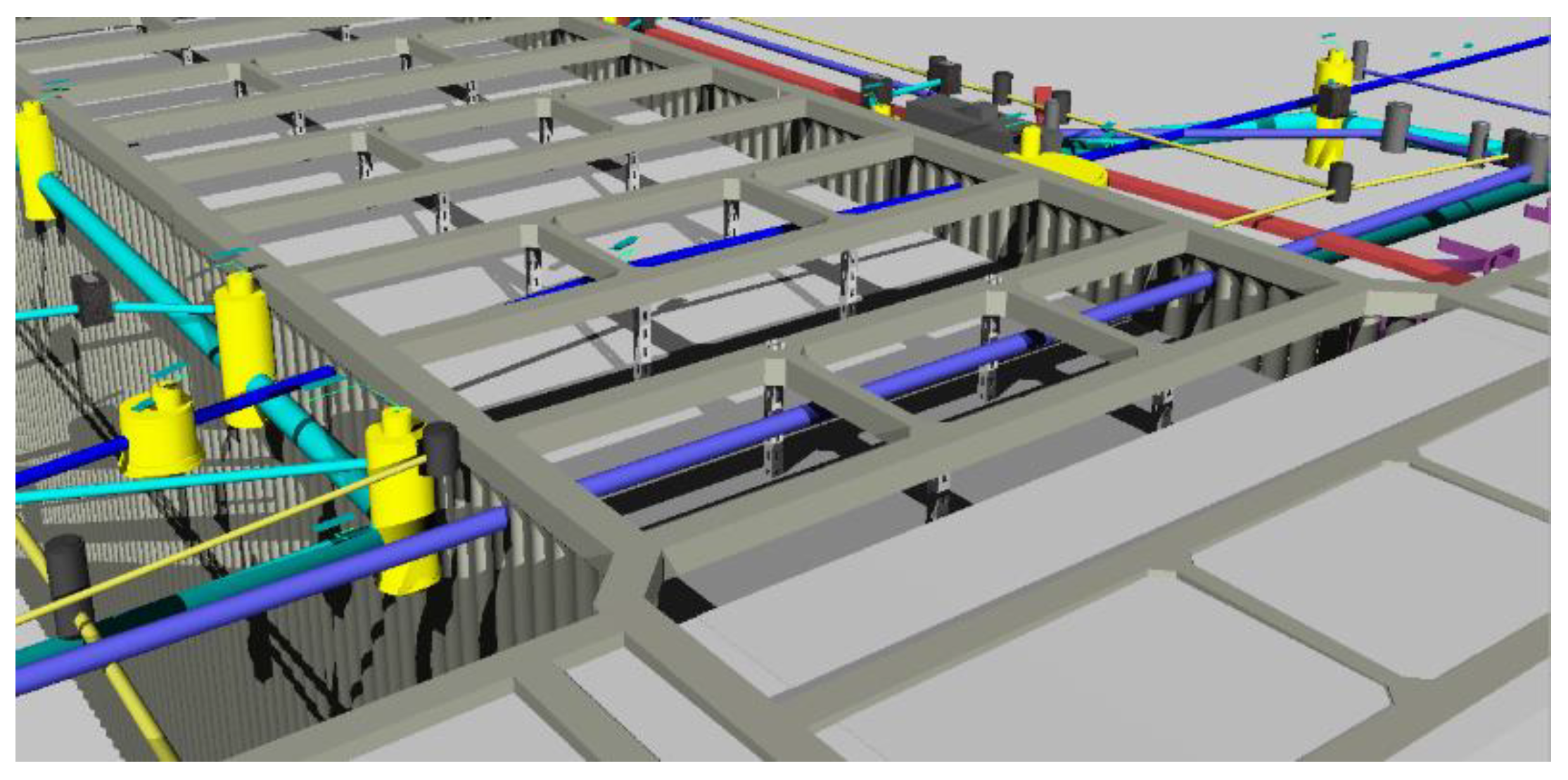
The deep excavation is supported by diaphragm walls of 0.6 m in thickness on its general segments of the perimeter, while on the specific segments of the perimeter with the interruption of the buried pipelines, the deep excavation is supported by the Metro Jet System (MJS) retaining wall. The MJS retaining wall extends to a distance of 8.5 m away from the excavation side. The net distance between the MJS retaining wall is no less than 0.5 m, and the net distance between the diaphragm wall and the pipelines is no less than 0.8 m. In addition, the excavation support system also includes concrete struts, steel struts, cast-in-situ bored (CISB) piles, lattice columns, and high-pressure jet grouting (HPJR) piles. A schematic diagram showing the excavation support system is presented in Figure 3.

2.3. Pipeline Suspension Structure

During the construction of the deep excavation, the pipelines are protected in situ by using the suspension method. The pipeline suspension structure takes advantage of the excavation support system. Three of the concrete struts are used as the bearing system of the pipeline suspension structure, and the pipelines are suspended from the selected concrete struts by using the finely rolled rebars, as depicted in Figure 4. In order to achieve sufficient flexural rigidity of the three concrete struts being parts of the pipeline suspension structure, twelve lattice columns are installed below them. The longitudinal distance between two adjacent lattice columns is 6 m. The 32a U-bar and steel plate are combined to serve as the cork base of the pipeline suspension structure. The cork base is connected to the concrete struts through the fine-rolled rebars. A schematic diagram of the pipeline suspension structure is shown in Figure 4. Compared to the traditional ones, this pipeline suspension structure has the following advantages: (1) it reduces the construction cost by taking advantage of the excavation support system, and (2) the deformation of the protected pipeline can be dynamically adjusted during the excavation by controlling the length of the fine rolled rebar.

2.4. Geological and Hydrologic Conditions

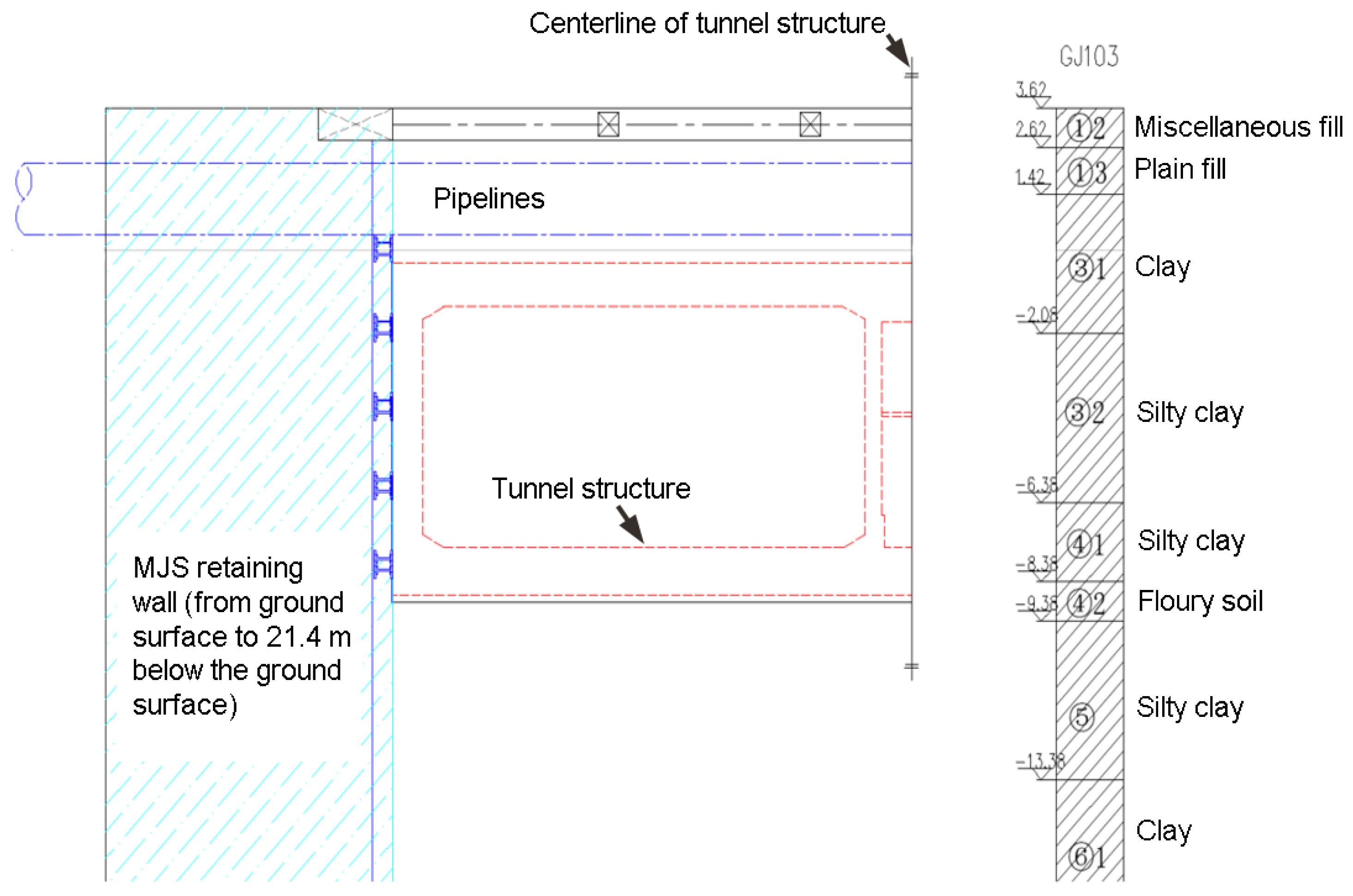
The soil layers involved in the YRNE Project, from the ground surface to the bottom of the MJS retaining wall, are, respectively, miscellaneous fill, plain fill, clay, silty clay, floury soil, silty clay, and clay, as schematically shown in Figure 5. The excavation bottom is mainly located within the floury soil layer. By performing in situ and laboratory tests, the basic properties of the soil are obtained. Table 2 summarizes the thickness and the basic properties of these soil layers. Note that the soil layer number has been depicted in Figure 5. The groundwater that has an effect on this project primarily includes phreatic aquifer, feeble confined water, and confined water. The groundwater table is about 5.0 m below the ground surface. The bottom of the deep excavation is mainly located within the feeble confined water layer.

3. Numerical Modelling

3.1. Finite Element Analysis Software

The commercial software for finite element analysis (FEA), Midas GTS NX, is adopted in this study. It is characterized by real 3D geometry modeling, a powerful mesh generator, a fast analysis solver, and outstanding post-processing. This FEA software has been widely used for advanced geotechnical analysis in terms of geomaterial deformation and stability, groundwater flow, dynamic vibrations, and soil-structure interactions in 2D and 3D.

3.2. Meshing and Boundary Conditions

The meshing of the finite element analysis model established in this study is presented in Figure 6. Considering the three-dimensional size of the deep-braced excavation, the dimension of the overall model is selected as 200 m × 150 m × 40 m, which has eliminated the boundary effect. To simulate the deep-braced excavation in a reasonable way, the boundary conditions of the finite element analysis model are set as free at the top surface, rolled on the four vertical sides, and fixed at the bottom surface.

3.3. Parameters Used for Finite Element Analysis

The Mohr–Coulomb (MC) model is used for simulating the constitutive behavior of the soil in the YRNE Project. The MC model is the most widely used constitutive model in geotechnical simulations, thanks to the simplicity and the easy availability of the model parameter. The yield criterion of the MC model can be written as
σ 1 σ 3 2 = σ 1 + σ 3 2 sin φ + c cos φ
where σ1 and σ3 are the major and the minor principal stresses, respectively; c is the cohesion; and φ is the angle of internal friction.
The soil parameters required for the MC model are summarized in Table 2. As for the excavation support system and the pipeline suspension structure, the linear elastic model is used to simulate their behavior, considering that the stress–strain relations of these structural components are always within the elastic domain during the construction of the deep-braced excavation. Table 3 summarizes the parameters required for the simulations of the excavation support system and the pipeline suspension structure.

3.4. Excavation Sequence Simulation

According to the actual excavation sequence, the construction process of the deep-braced excavation can be simulated in the following ten Excavation Steps:
Excavation Step 1: Reproduce the ground state of stress, and eliminate the ground displacement;
Excavation Step 2: Activate the excavation support structures, including the diaphragm wall, MJS retaining wall, and CISB piles;
Excavation Step 3: Excavate to the bottom of the concrete struts, and activate the ring beam and the concrete struts;
Excavation Step 4: Excavate to the elevation of 0.5 m below the pipelines, and activate the pipeline suspension structure;
Excavation Step 5: Excavate to the elevation of 0.5 m below the first-level steel struts, and activate the first-level steel struts;
Excavation Step 6: Excavate to the elevation of 0.5 m below the second-level steel struts, and activate the second-level steel struts;
Excavation Step 7: Excavate to the elevation of 0.5 m below the third-level steel struts, and activate the third-level steel struts;
Excavation Step 8: Excavate to the bottom of the excavation, and activate the cushion and the tunnel floor;
Excavation Step 9: Activate the side walls, middle walls, and roof of the tunnel structure; and
Excavation Step 10: Deactivate the pipeline suspension structure and the lattice columns, and backfill the soil.

4. Validation of Finite Element Method

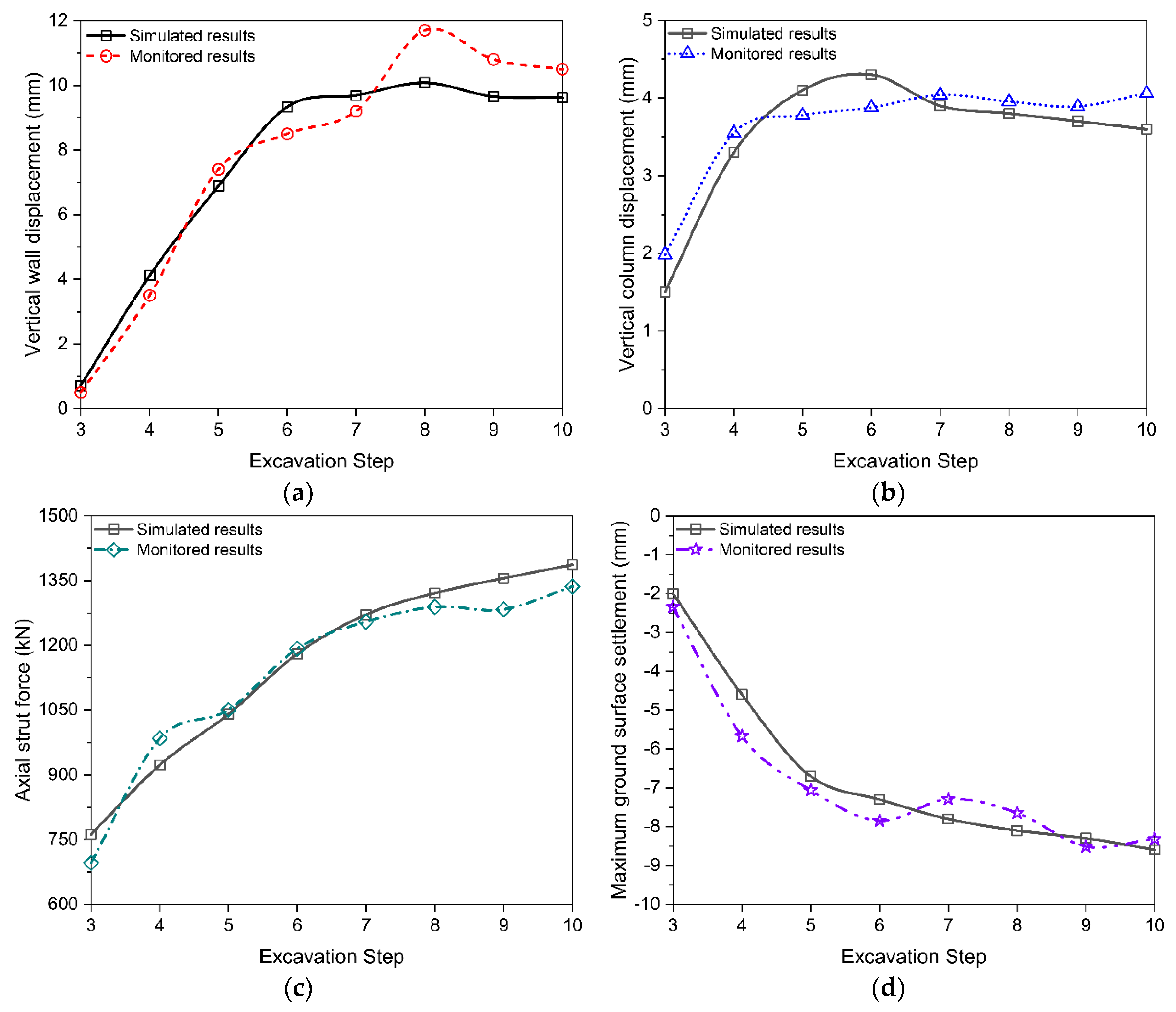
The monitoring data for the performance of the deep-braced excavation observed at the site can be used to validate the finite element method adopted in this study. During the construction process, the monitored items include the ground surface settlements, pipeline displacements, displacements at the diaphragm wall top, lattice column displacements, groundwater level, and axial forces in concrete and steel struts. A plan view showing the arrangement of these monitored items is presented in Figure 7, where DB59-1–DB59-5 and DB60-1–DB60-5 denote ten monitoring points for ground surface settlements, JS1-1–JS1-15 denote fifteen monitoring points for DN1800 pipeline displacements, JS2-1–JS2-15 denote fifteen monitoring points for DN1400 pipeline displacements, P117 and P118 denote two monitoring points for displacements at diaphragm wall top, LZ58 denotes one monitoring points for lattice column displacements, W57 and W58 denote two monitoring points for groundwater level, ZL29 denotes one monitoring point for axial forces in concrete strut, and GL29 denotes one monitoring points for axial forces in steel strut. The devices used for monitoring these items and their versions are summarized in Table 4.
In order to validate the finite element method adopted in this study, a comparison is made between the simulated results by the finite element method and the monitored results in the field in terms of displacements at diaphragm wall top, lattice column displacements, axial forces in struts, and ground surface settlements, as shown in Figure 8. The comparison indicates that the simulated results by the finite element method agree well with the monitored results, demonstrating the validity of the finite element method adopted in this study. Moreover, the slight difference between the simulated and the monitored results are caused by various factors, such as the simplification of the excavation support system, the inability of the MC model to describe the true behavior of the soil, and the complex geological conditions that cannot be reproduced in the finite element analysis.

5. Results and Discussion

The simulated results describing the performance of the deep-braced excavation by the validated finite element method are presented in this section. In detail, this section analyzes the deformation characteristics of the diaphragm wall and the MJS retaining wall, the distribution of the internal forces in the concrete struts and steel struts, and the vertical displacements of the pipelines. In addition, a brief discussion of the supporting effect of the pipeline suspension structure is also presented.

5.1. Deformation Characteristics of Diaphragm Wall and MJS Retaining Wall

Figure 9 presents the displacement contours of the diaphragm wall and MJS retaining wall at four different Excavation Steps (i.e., Excavation Steps 3, 5, 6, and 8). A description of these Excavation Steps has been given in Section 3.4. It can be seen from Figure 8 that both the diaphragm wall and the MJS retaining wall tend to move towards the excavation with advancing excavation. The deformation of the diaphragm wall and the MJS retaining wall increases with increasing the excavation depth. When the final excavation depth (i.e., 12.5 m) is reached at Excavation Step 8, the maximum deformation of the diaphragm wall, 14 mm, is achieved.

5.2. Distribution of Internal Forces in Concrete Strut

Figure 10 presents the contours of the internal forces in the concrete strut at Excavation Step 8. The internal forces include axial force (Figure 10a), shear force in the Y direction (Figure 10b), shear force in the Z direction (Figure 10c), the bending moment in the Y direction (Figure 10d), and bending moment in the Z direction (Figure 10e). The results indicate that the maximum magnitudes of the axial force, shear force in the Y direction, the bending moment in the Y direction, shear force in the Z direction, and bending moment in the Z direction in the concrete strut are, respectively, 269 kN, 397 kN, 79 kN·m, 24.5 kN, and 896 kN·m. Moreover, the distribution of the shear forces in the Y and Z directions along the axis of the concrete strut is in a linear manner, while the distribution of the bending moments in the Y and Z directions is in a symmetric manner.

5.3. Distribution of Internal Forces in Steel Strut

Figure 11 presents the contours of the axial force, shear force in the Y direction, shear force in the Z direction, the bending moment in the Y direction, and bending moment in the Z direction in the steel strut at Excavation Step 8. It can be indicated that the maximum axial force in the steel strut is 237 kN. The shear force in the Y direction is of linear distribution along the axis of the steel strut. The maximum shear force in the Y direction is located at the third steel strut, with its magnitude being 149 kN. However, compared to the magnitude of the maximum shear force in the Y direction, the maximum shear force in the Z direction is negligible, with its magnitude being merely 8.11 kN. The distribution of the bending moments in both Y and Z directions is almost symmetric with regard to the middle of the steel strut. The maximum magnitudes of the bending moments in Y and Z directions are, respectively, 23 and 315 kN·m, which are both reached at the third steel strut.

5.4. Vertical Displacements of Pipelines

Figure 12 presents the contours of the vertical displacements of pipelines at five different Excavation Steps (i.e., Excavation Steps 4, 5, 6, 7, and 8). It can be seen that at Excavation Steps 4 and 5, settlements of the pipelines occur for the entire length of the two pipelines, with the maximum settlement being 3 mm. This is attributed to the fact that the pipeline suspension structure has not taken much effect during the early phase after installation. At the following Excavation Steps, a heave of the pipelines occurs. The heave of the pipelines is primarily caused by the basal heave of the excavation after soil removal. Due to the occurrence of the basal heave, the lattice columns move upward, which raises the concrete struts. The rise of the concrete struts is eventually transferred to the pipelines by virtue of the pipeline suspension structure. With an increase in the excavation depth, the heave of the pipelines increases due to an increase in the basal heave of the excavation. The maximum heave of the pipelines, 13 mm, is achieved when the final excavation depth (i.e., 12.5 m) is reached. In addition, the maximum heave of pipeline DN1400 is 1 mm greater than that of pipeline DN1800, which may be attributed to the lighter weight of pipeline DN1400.

5.5. Discussion of Supporting Effect of Pipeline Suspension Structure (PSS)

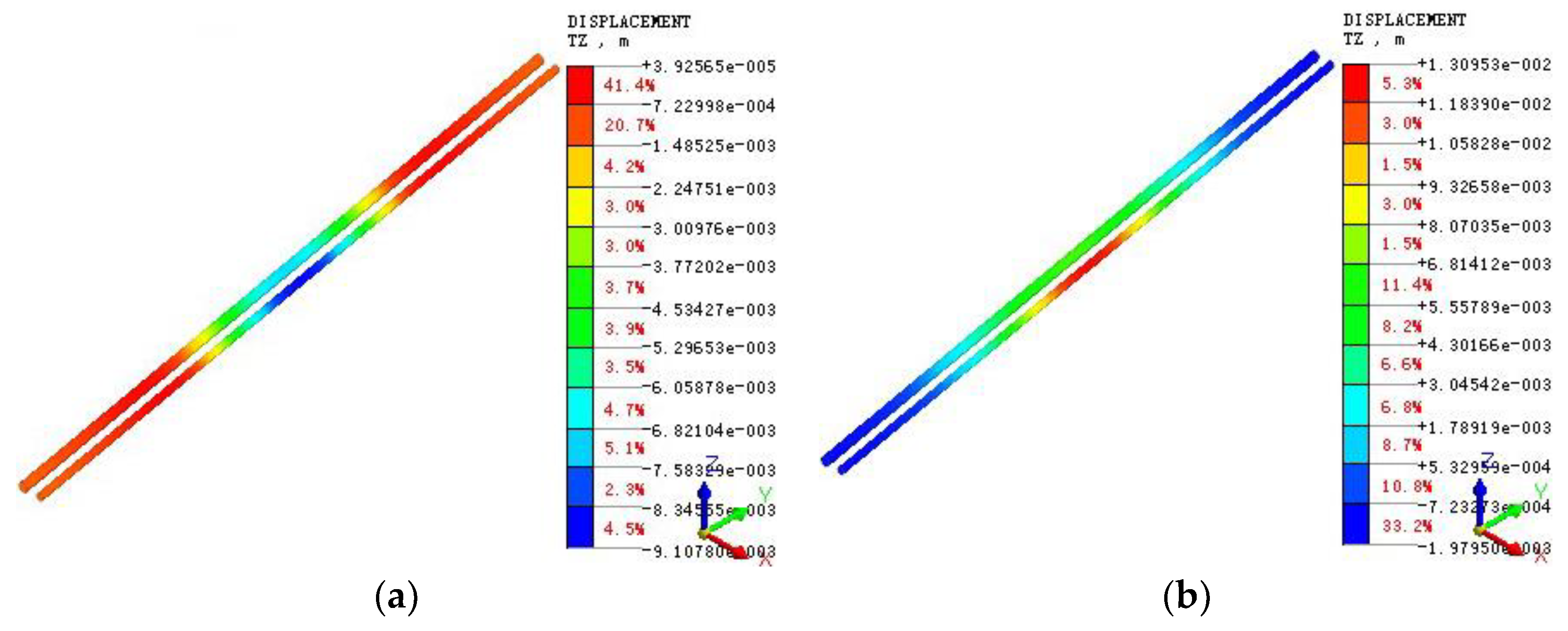
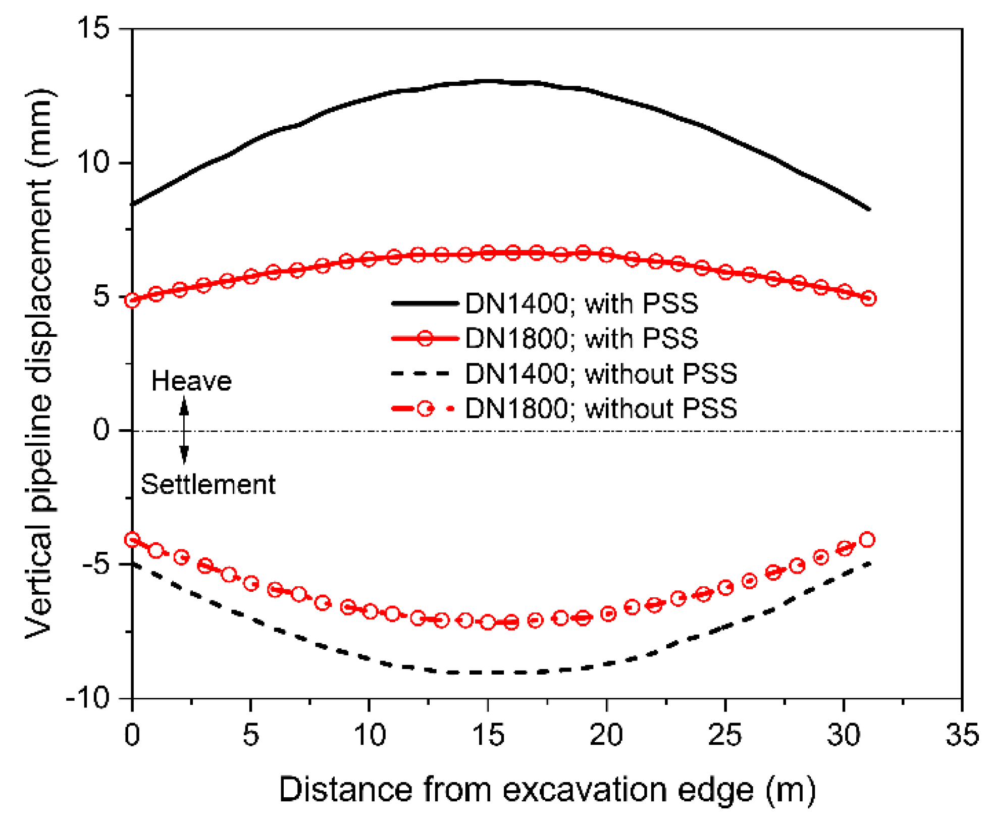
The effectiveness of the supporting system is discussed by comparing the results of two cases: one is the above-mentioned YRNE Project, where PSS is installed, and the other is the same project but without PSS. By performing finite element analysis using the material parameters, constitutive models, and excavation simulation sequence for the case with PSS, the results for the case without PSS are also obtained. Figure 13 compares the contours of the vertical displacements of pipelines at Excavation Step 8 between the cases with and without installing the pipeline suspension structure. The distributions of the vertical displacements of the pipelines along the distance from the excavation edge are compared in Figure 14 for the two cases described above.
From the results presented in Figure 13 and Figure 14, it can be inferred that settlements of pipelines will occur for the case without installing PSS due to the action of gravity. The pipeline settlements peak in the middle of the excavation. Under the condition of no suspension support, both of the two pipelines exhibit a tendency for settlement. The maximum settlement of pipeline DN1400 is 9 mm, which is slightly greater than that of pipeline DN1800 (i.e., 6 mm). Under the condition where the PSS is installed, both of the two pipelines tend to be uplifted during the following Excavation Steps. The maximum heave of the pipeline occurs at pipeline DN1400 with a magnitude of 13 mm, which is slightly greater than that occurred at pipeline DN1800. During the construction process, the heave of the pipelines for the case with installing PSS can be eliminated by lowering the elevation of the cork base of the pipeline suspension structure. This operation should be slow and of uniform velocity, with the help of a chain hoist. Therefore, because of the existence of the pipeline suspension structure, the initial deformation pattern and stress state of the pipelines before the commencement of the construction can be maintained after the completion of the construction. However, in the case without PSS, the pipelines will always be in a curved state of deformation pattern during the operation life cycle of the WY Tunnel, which will jeopardize the structural integrity and the durability of the pipelines.

6. Conclusions

An unusual deep-braced excavation case history in Suzhou, China, is reported. This excavation is spanned by two shallowly buried large-diameter pressurized pipelines. As the pipelines need to be protected in situ during the construction of the excavation, a pipeline suspension structure is installed in addition to the excavation support system. Three-dimensional finite element analysis is performed to capture the performance of this deep-braced excavation at different stages. Based on the part of the field monitoring data, the validity of the finite element method adopted has been demonstrated. The conclusions drawn from this study can be summarized as follows.
(1)
Both the diaphragm wall and the MJS retaining wall have a tendency to deform towards the excavation with proceeding the Excavation Step. The deformation of these walls constantly increases with an increase in the excavation depth.
(2)
When the final excavation depth is reached, the distribution of the shear forces in the Y and Z directions along the axis of the concrete strut is in a linear manner, while the distribution of the bending moments in the Y and Z directions is in a symmetric manner.
(3)
At the final excavation depth, the shear force in the Y direction is of linear distribution along the axis of the steel strut, and the distribution of the bending moments in both Y and Z directions is almost symmetric with regard to the middle of the steel strut. The magnitude of the maximum shear force in the Z direction is negligible compared to the magnitude of the maximum shear force in the Y direction.
(4)
With an increase in the excavation depth, the heave of the pipelines increases due to an increase in the basal heave of the excavation. The maximum heave of pipeline DN1400 is 1 mm greater than that of pipeline DN1800, which may be attributed to the lighter weight of pipeline DN1400.
(5)
The installation of the pipeline suspension structure is beneficial for the structural integrity and the safety of the pipelines during both the construction phase and the operational phase of the tunnel. This benefit is obtained by implementing conveniently the operation that the elevation of the pipeline suspension structure cork base is stably lowered during the construction period.

Author Contributions

Conceptualization, P.G. and Y.W.; methodology, P.G.; software, P.G. and N.G.; validation, H.L., F.L. (Fangang Li), and P.G.; investigation, F.L. (Fangang Li), F.L. (Feng Lin) and L.M.; supervision, Y.W.; project administration, Y.Z.; funding acquisition, Y.W. All authors have read and agreed to the published version of the manuscript.

Funding

This research work was funded by the National Natural Science Foundation of China (42077249, 51774107).

Data Availability Statement

The data presented in this study are available on request from the corresponding author P.G.

Acknowledgments

The authors thank the anonymous reviewers for their constructive comments.

Conflicts of Interest

The authors declare no conflict of interest.

References

  1. Tan, Y.; Lu, Y.; Wang, D. Deep excavation of the Gate of the Orient in Suzhou stiff clay: Composite earth retaining systems and dewatering plans. J. Geotech. Geoenviron. Eng. 2018, 144, 05017009. [Google Scholar] [CrossRef]
  2. Oztoprak, S.; Cinicioglu, S.F.; Oztorun, N.K.; Alhan, C. Impact of neighbouring deep excavation on high-rise sun plaza building and its surrounding. Eng. Fail. Anal. 2020, 111, 104495. [Google Scholar] [CrossRef]
  3. Tan, Y.; Wei, B.; Zhou, X.; Diao, Y. Lessons learned from construction of Shanghai metro stations: Importance of quick excavation, prompt propping, timely casting, and segmented construction. J. Perform. Constr. Facil. 2015, 29, 04014096. [Google Scholar] [CrossRef]
  4. Li, D.; Yan, C. Building deformation prediction based on ground surface settlements of metro-station deep excavation. Adv. Civ. Eng. 2018, 2018, 6050353. [Google Scholar] [CrossRef]
  5. Liu, B.; Xu, W.; Zhang, D.; Zhang, Q. Deformation behaviors and control indexes of metro-station deep excavations based on case histories. Tunn. Undergr. Space Technol. 2022, 122, 104400. [Google Scholar] [CrossRef]
  6. Shi, H.; Jia, Z.; Wang, T.; Cheng, Z.; Zhang, D.; Bai, M.; Yu, K. Deformation characteristics and optimization design for large-scale deep and circular foundation pit partitioned excavation in a complex environment. Buildings 2022, 12, 1292. [Google Scholar] [CrossRef]
  7. Hou, Y.M.; Wang, J.H.; Zhang, L.L. Finite-element modeling of a complex deep excavation in Shanghai. Acta Geotech. 2009, 4, 7–16. [Google Scholar] [CrossRef]
  8. Li, M.-G.; Chen, J.-J.; Xu, A.-J.; Xia, X.-H.; Wang, J.-H. Case study of innovative top-down construction method with channel-type excavation. J. Constr. Eng. Manag. 2014, 140, 05014003. [Google Scholar] [CrossRef]
  9. Whittle, A.J.; Hashash, Y.M.A.; Whitman, R.V. Analysis of deep excavation in Boston. J. Geotech. Eng. 1993, 119, 69–90. [Google Scholar] [CrossRef]
  10. Huang, X.; Schweiger, H.F.; Huang, H. Influence of deep excavations on nearby existing tunnels. Int. J. Geomech. 2013, 13, 170–180. [Google Scholar] [CrossRef]
  11. Wang, J.; Xiang, H.; Yan, J. Numerical simulation of steel sheet pile support structures in foundation pit excavation. Int. J. Geomech. 2019, 19, 05019002. [Google Scholar] [CrossRef]
  12. Issa, U.; Saeed, F.; Miky, Y.; Alqurashi, M.; Osman, E. Hybrid AHP-fuzzy TOPSIS approach for selecting deep excavation support system. Buildings 2022, 12, 295. [Google Scholar] [CrossRef]
  13. Hong, L.; Chen, L.; Wang, X. Reliability analysis of serviceability limit state for braced excavation considering multiple failure modes in spatially variable soil. Buildings 2022, 12, 722. [Google Scholar] [CrossRef]
  14. Gong, X.-n.; Zhang, X.-c. Excavation collapse of Hangzhou subway station in soft clay and numerical investigation based on orthogonal experiment method. J. Zhejiang Univ.-SCI A 2012, 13, 760–767. [Google Scholar] [CrossRef]
  15. He, L.; Liu, Y.; Bi, S.; Wang, L.; Broggi, M.; Beer, M. Estimation of failure probability in braced excavation using Bayesian networks with integrated model updating. Undergr. Space 2020, 5, 315–323. [Google Scholar] [CrossRef]
  16. Do, T.-N.; Ou, C.-Y.; Chen, R.-P. A study of failure mechanisms of deep excavations in soft clay using the finite element method. Comput. Geotech. 2016, 73, 153–163. [Google Scholar] [CrossRef]
  17. Chen, R.P.; Li, Z.C.; Chen, Y.M.; Ou, C.Y.; Hu, Q.; Rao, M. Failure investigation at a collapsed deep excavation in very sensitive organic soft clay. J. Perform. Constr. Facil. 2015, 29, 04014078. [Google Scholar] [CrossRef]
  18. Tan, Y.; Lu, Y. Forensic diagnosis of a leaking accident during excavation. J. Perform. Constr. Facil. 2017, 31, 04017061. [Google Scholar] [CrossRef]
  19. Hu, Q.; Xu, X.B.; Huang, T.M.; Lu, S.Q. Collapse of a deep excavation and its reconstruction in soft soil of Nanjing, China. Proc. Inst. Civ. Eng.-Forensic Eng. 2021, 174, 1–7. [Google Scholar] [CrossRef]
  20. Liu, G.B.; Ng, C.W.W.; Wang, Z.W. Observed performance of a deep multistrutted excavation in Shanghai soft clays. J. Geotech. Geoenviron. Eng. 2005, 131, 1004–1013. [Google Scholar] [CrossRef]
  21. Masini, L.; Gaudio, D.; Rampello, S.; Romani, E. Observed performance of a deep excavation in the historical center of Rome. J. Geotech. Geoenviron. Eng. 2021, 147, 05020015. [Google Scholar] [CrossRef]
  22. Cheng, K.; Xu, R.; Ying, H.; Gan, X.; Zhang, L.; Liu, S. Observed performance of a 30.2 m deep-large basement excavation in Hangzhou soft clay. Tunn. Undergr. Space Technol. 2021, 111, 103872. [Google Scholar] [CrossRef]
  23. Zhang, R.; Wu, C.; Goh, A.T.C.; Böhlke, T.; Zhang, W. Estimation of diaphragm wall deflections for deep braced excavation in anisotropic clays using ensemble learning. Geosci. Front. 2021, 12, 365–373. [Google Scholar] [CrossRef]
  24. Guo, P.; Lei, G.; Luo, L.; Gong, X.; Wang, Y.; Li, B.; Hu, X.; Hu, H. Soil creep effect on time-dependent deformation of deep braced excavation. Adv. Mater. Sci. Eng. 2022, 2022, 5655592. [Google Scholar] [CrossRef]
  25. Guo, P.; Gong, X.; Wang, Y. Displacement and force analyses of braced structure of deep excavation considering unsymmetrical surcharge effect. Comput. Geotech. 2019, 113, 103102. [Google Scholar] [CrossRef]
  26. Chen, H.; Li, J.; Yang, C.; Feng, C. A theoretical study on ground surface settlement induced by a braced deep excavation. Eur. J. Environ. Civ. Eng. 2022, 26, 1897–1916. [Google Scholar] [CrossRef]
  27. Liu, J.; Shi, C.; Lei, M.; Cao, C.; Lin, Y. Improved analytical method for evaluating the responses of a shield tunnel to adjacent excavations and its application. Tunn. Undergr. Space Technol. 2020, 98, 103339. [Google Scholar] [CrossRef]
  28. Guo, P.; Liu, F.; Lei, G.; Li, X.; Zhu, C.; Wang, Y.; Lu, M.; Cheng, K.; Gong, X. Predicting response of constructed tunnel to adjacent excavation with dewatering. Geofluids 2021, 2021, 5548817. [Google Scholar] [CrossRef]
  29. Zhang, D.-M.; Xie, X.-C.; Li, Z.-L.; Zhang, J. Simplified analysis method for predicting the influence of deep excavation on existing tunnels. Comput. Geotech. 2020, 121, 103477. [Google Scholar] [CrossRef]
  30. Kung, G.T.C.; Juang, C.H.; Hsiao, E.C.L.; Hashash, Y.M.A. Simplified model for wall deflection and ground-surface settlement caused by braced excavation in clays. J. Geotech. Geoenviron. Eng. 2007, 133, 731–747. [Google Scholar] [CrossRef]
  31. Ou, C.-Y.; Hsieh, P.-G. A simplified method for predicting ground settlement profiles induced by excavation in soft clay. Comput. Geotech. 2011, 38, 987–997. [Google Scholar] [CrossRef]
  32. Hu, B.; Li, X.; Huang, D. Safety risk analysis and protective control of existing pipelines affected by deep pit excavation in metro construction. Model. Simul. Eng. 2019, 2019, 3643808. [Google Scholar] [CrossRef] [Green Version]
  33. Jiang, N.; Zhu, B.; He, X.; Zhou, C.; Luo, X.; Wu, T. Safety assessment of buried pressurized gas pipelines subject to blasting vibrations induced by metro foundation pit excavation. Tunn. Undergr. Space Technol. 2020, 102, 103448. [Google Scholar] [CrossRef]
  34. Zhang, Z.; Zhang, M.; Zhao, Q. A simplified analysis for deformation behavior of buried pipelines considering disturbance effects of underground excavation in soft clays. Arab. J. Geosci. 2015, 8, 7771–7785. [Google Scholar] [CrossRef]
  35. Kog, Y.C. Buried pipeline response to braced excavation movements. J. Perform. Constr. Facil. 2010, 24, 235–241. [Google Scholar] [CrossRef]
  36. Linehan, P.W.; Longinow, A.; Dowding, C.H. Pipe response to pile driving and adjacent excavation. J. Geotech. Eng. 1992, 118, 300–316. [Google Scholar] [CrossRef]
  37. Tan, Y.; Lu, Y. Responses of shallowly buried pipelines to adjacent deep excavations in Shanghai soft ground. J. Pipeline Syst. Eng. Pract. 2018, 9, 05018002. [Google Scholar] [CrossRef]
  38. Chen, H.; Li, J.; Li, L. Performance of a zoned excavation by bottom-up technique in Shanghai soft soils. J. Geotech. Geoenviron. Eng. 2018, 144, 05018003. [Google Scholar] [CrossRef]
Figure 1. Schematic diagram of the relative position between pipelines and tunnel: (a) Transverse section; (b) Longitudinal section.
Water 14 03867 g001
Figure 2. A photograph of the pipelines in the YRNE Project.
Water 14 03867 g002
Figure 3. Schematic diagram of the excavation support system.
Water 14 03867 g003
Figure 4. Schematic diagram of the pipeline suspension structure: (a) Transverse section; (b) Longitudinal section.
Water 14 03867 g004
Figure 5. Profile of the soil layers at the site.
Water 14 03867 g005
Figure 6. Meshing of the finite element analysis model: (a) Overall model; (b) Diaphragm walls; (c) Lattice columns; (d) Concrete struts; (e) Steel struts; (f) Pipeline suspension structure.
Water 14 03867 g006
Figure 7. Plan view showing arrangement of the monitored items: (a) Pipeline displacements; (b) Ground surface settlements, displacements at diaphragm wall top, lattice column displacements, groundwater level, and axial forces in concrete and steel struts.
Water 14 03867 g007
Figure 8. Comparison of simulated results by the finite element method and monitored results in terms of (a) Vertical wall displacement at P117; (b) Vertical column displacement at LZ58; (c) Axial strut force at ZL29; (d) Maximum ground surface settlement along DB59-1–DB59-5.
Water 14 03867 g008
Figure 9. Displacement contours of diaphragm wall and MJS retaining wall at: (a) Excavation Step 3; (b) Excavation Step 5; (c) Excavation Step 6; (d) Excavation Step 8.
Water 14 03867 g009
Figure 10. Contours of internal forces in concrete strut at Excavation Step 8: (a) Axial force; (b) Shear force in Y direction; (c) Shear force in Z direction; (d) Bending moment in Y direction; (e) Bending moment in Z direction.
Water 14 03867 g010aWater 14 03867 g010b
Figure 11. Contours of internal forces in steel strut at Excavation Step 8: (a) Axial force; (b) Shear force in Y direction; (c) Shear force in Z direction; (d) Bending moment in Y direction; (e) Bending moment in Z direction.
Water 14 03867 g011aWater 14 03867 g011b
Figure 12. Contours of vertical displacements of pipelines at (a) Excavation Step 4; (b) Excavation Step 5; (c) Excavation Step 6; (d) Excavation Step 7; (e) Excavation Step 8.
Water 14 03867 g012
Figure 13. Contours of vertical displacements of pipelines at Excavation Step 8: (a) without installing pipeline suspension structure; (b) with installing pipeline suspension structure.
Water 14 03867 g013
Figure 14. Comparison of vertical displacements of pipelines between cases with and without installing pipeline suspension structure (PSS).
Water 14 03867 g014
Table 1. Summary of some of the typical characteristics of the pipelines in the YRNE Project.
PipelineMaterialCover Depth
(m)
Diameter
(m)
Wall Thickness
(mm)
Internal Pressure
(MPa)
DN1800steel1.45–1.551.8160.3
DN1400steel1.60–1.741.4140.2
Table 2. Summary of the thickness and properties of the soil layers.
Soil Layer
Number
Thickness
(m)
Unit Weight
(kN/m3)
Elasticity Modulus
(MPa)
Poisson’s Ratio
(-)
Friction Angle
(°)
Cohesion
(kPa)
①2118.53.50.23125
①31.21940.21012
③13.519.3250.316.033.1
③24.318.6200.3317.019.8
④1218.8220.3619.219.6
④2118.4300.2517.717.2
418.5200.3315.939.4
⑥19.519.8200.318.517.6
Table 3. Parameters required for the simulation of the excavation support system and the pipeline suspension structure.
StructureUnit Weight
(kN/m3)
Elastic Modulus
(MPa)
Poisson’s Ratio
(-)
Remark
Diaphragm wall253 × 1040.2Thickness = 0.6 m; Depth = 25 m
MJS wall201 × 1040.2From ground surface to −21.4 m
CISB pile203 × 1040.2Diameter = 0.8 m; Length = 30 or 38 m
Ring beam253 × 1040.2Sectional dimension = 1 m × 0.8 m
Concrete strut253 × 1040.2Sectional dimension = 0.8 m × 0.8 m
Steel strut78.52 × 1050.25Diameter = 609 mm; Wall thick. = 16 mm
Lattice column78.52 × 1050.25Longitudinal interval = 6 m
Cork base78.52 × 1050.25Using 32a U-bar
Fine rolled rebar78.52 × 1050.25Diameter = 25 mm
Table 4. Summary of the monitoring devices used in this deep-braced excavation and their versions.
Monitored ItemDevice UsedVersion
Horizontal disp. at diaphragm wall topTotal station instrumentTCRA1201
Vertical disp. at diaphragm wall topTotal station instrumentTCRA1201
Pipeline displacementsTotal station instrumentTCRA1201
Ground surface settlementsSingle-point settling meterYH02-A20
Axial forces in strutsVibrating string-type steel bar meterGJJ10
Groundwater levelPneumatic water level gaugeYH04-A06
Publisher’s Note: MDPI stays neutral with regard to jurisdictional claims in published maps and institutional affiliations.