Abstract
As the process before the transporting of the capsule in a hydraulic capsule pipeline system, the capsule’s threshold of motion process is often tested in the horizontal straight pipe. However, the result of the physical test in this work shows that the wheeled capsule more easily start-moves in a horizontal bent pipe. Thus, the numerical simulation and the theory analysis were used to study the wheeled capsule’s threshold of motion process in the bent pipe. The simulation results demonstrate that the velocity magnitude of the water flow was asymmetric between the inner part and the outer part of the section closing on the wheeled capsule. This was unlike the water flow of the section in the straight pipe. From this result, a new mechanical model was proposed that divides the wheeled capsule into two parts. The two parts of the mechanical model correspond to the two parts of the section. Then, the deduction has shown that the bolsters of the inner part of the wheeled capsule in the bent pipe endured lower maximum static friction than those in the straight pipe. The whole wheeled capsule was more unstable in the bent pipe than in the straight pipe because of the additional drag force induced by the centrifugal effect of the bent pipe’s water flow.
1. Introduction
Pipeline transportation is one of the most useful transportation methods and is of vital strategic importance. Additionally, the suspension of the “Nord Stream” pipeline gave us a warning about transportation problems under the shortage of fossil fuels [1]. There is a true need for transportation without the use of fossil fuels. Hydraulic capsule pipeline transportation (HCP) is such a transportation method [2]. Its energy sources can be the potential energy of water in lakes or reservoirs, the kinetic energy of rivers, and other green energy sources [3].
The HCP’s mechanics [4] determine the water flow in the pipeline and the environment of the pressured pipe flow field. The pipe flow pushes the capsule moving in the pipeline, and the capsule can load the materials. The materials are moved by water flow by the means of the capsule, and this is the transportation process of a HCP. We can find three processes of transportation in HCPs. The first is the threshold of motion process; next is the transporting process; and the last is the arriving process. In actual studies, the threshold of motion and the transporting processes are the most important [5], so they mainly focus on these two processes.
About the transporting process: Ulusarslan and Teke et al. [6,7] studied the energy loss of spherical capsules moving in the horizontal bent pipeline, and gave a relation formula for energy loss and distance between capsules while the capsules moved. Asim et al. [8,9] calculated the pressure loss’s semiempirical formula for cylindrical and spherical capsules of various sizes in a horizontal bent pipeline. Li et al. [10,11] researched cylindrical capsules of different sizes with unique loadings, under different flows, by means of physical experimentation, and deduced a mathematical model of a cylindrical capsule moving in a straight pipe. They also deduced the energy consumption of the cylindrical capsule’s transportation. Zhang et al. [12] studied the energy consumption of a cylindrical capsule as well. From the studies mentioned above, the conclusion is that: spherical capsules and cylindrical capsules have been well studied by physical experimentation and numerical simulation, and theoretical analysis has involved energy consumption formulas or models.
The threshold of motion process has not been well studied. Liu et al. [13] tested a cylindrical capsule’s threshold of motion process and measured the drag and lift. They found that the drag was far greater than the lift of the capsule. Lin et al. [14] considered that the capsule’s threshold of motion can be divided into four stages. Sun et al. [15] tested a cylindrical capsule’s threshold of motion and found that the threshold of motion of capsules related to the flow, the size, and the loading. These are the representative studies so far, and we should emphasize that these studies have all focused on a capsule’s threshold of motion in a straight pipe. A wheeled cylindrical capsule’s threshold of motion has not been studied. We would like to explain how this is significant.
The capsules were all studied by pressured pipe flow, and there has been a problem with water flow bypassing the capsule. For example, when a wheeled capsule moves in a pipe, there are three flow fields divided by the capsule. The upstream field of the capsule is behind the capsule, and the downstream field of the capsule is in front of the capsule. There is also a gap flow field between the capsule wall and the pipe wall. According to published studies, the water flow in the gap field can influence the capsule through friction drag. Yang et al. [16] studied the friction drag through the usage of strain gauges. The dynamic pressure difference between the front and back surfaces of the capsule would act as an effective force of pressure drag. Jia et al. [17] and Zhang et al. [18] studied the pressure drag of moving wheeled capsules. Zhao et al. [19] used the proper orthogonal decomposition method to analyze the fluid stresses and flow-induced vibration characteristics of the flow field of a wheeled capsule, and they claimed that the forces on the capsule are decided by the flow characteristics. In fact, the threshold of motion of the capsule is initiated by the pipe flow making the drag a little larger than the maximum static friction of the capsule. From the above studies, we can deduce that the flow field has significance to the moving and threshold of motion processes of the capsule.
In the opinion of the authors, the threshold of motion of the capsule should be analyzed in a bent pipe instead of a straight pipe. In short, the pipe flow is more rapid in a bent pipe than it in a straight pipe with the same inlet flow quantity [20]. According to the drag relation FD ∝ V2, the higher velocity would provide a larger drag force to make the capsule more easily start moving. To testify to the opinion mentioned above, this research is divided into the following sections. The second section presents the physical experiment’s arrangement. The third section presents the numerical simulation setup. The fourth section presents the flow characteristics and the mechanical analysis of the capsule’s threshold of motion. Last, we present the conclusions.
2. Physical Experiment
2.1. Wheeled Capsule
The physical model of a wheeled capsule and its schematic diagram are shown in Figure 1. The core of wheeled capsule pipeline transportation is the wheeled capsule. The wheeled capsule is the container of the loadings (raw material or others), and also the transportation device. The wheeled capsule consisted of a cylindrical container, covers, and bolsters. The cylindrical container was made of polymethyl methacrylate; the covers were deployed on the two sides of the container for waterproofing. The bolsters were forged by the cylindrical bars and link-planes. One group of three bolsters was deployed parallel to the cover plane, and the angle between any two bolsters was 120°. Each wheeled capsule had two groups of bolsters.
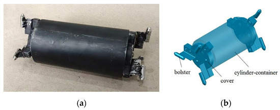
Figure 1.
Schematic diagram of the physical model of wheeled capsule: (a) physical diagram; (b) schematic diagram.
The bolsters made the cylindrical container concentrically move in the pipelines. The wheeled capsule had no energy source itself; its motion was caused by the water flow. The water flowed in the pipelines and made a pressure flow field; the pressurized pipe flow pushed the capsule. The mechanical energy of the water flow was converted into the kinetic energy of the wheeled capsule. This is the mechanism of HCP transportation.
The sizes of the wheeled capsule and the pipelines were designed by Gravity Similarity [10]. The pipeline’s diameter was 100 mm. The cylindrical container’s diameter was 60, 70, or 80 mm, its length was 100 or 150 mm. The bolster’s diameter was 8 mm. Additionally, a wheeled capsule of D = 70 mm and L = 150 mm was used for lower energy consumption; its designed loading was 1.5 kg.
2.2. The Experiment System
The experimental system had three parts: the flow control devices, the experimental pipelines, and the measuring device. The flow control devices included the tank, the centrifugal pump, and the flowmeter. The experimental pipelines were a horizontal straight pipeline and a horizontal bent pipeline; the inner diameter of each pipeline was 0.1 m, and the wall thickness of each pipeline was 5 mm. The measuring device was a particle image velocimeter (PIV) consisting of an image collection unit, a laser unit, a solving unit, and a coordinate unit. The image collection unit was two high-speed cameras with an angle in a vertical plane; the cameras focused on the same measuring section, and the laser unit lit the section by the light reflection of particles in the flow. The solving unit was used for processing the images, and the coordinate unit could regulate the location of the measurement section. A rectangular tank was also deployed for reducing the reflection impact of the pipeline on the laser. The schematic of the experimental system is shown in Figure 2.
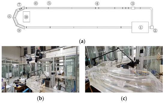
Figure 2.
Experiment system: (a) schematic diagram, ①-tank, ②-centrifugal pump, ③-flowmeter, ④-launch device, ⑤-flange, ⑥-straight pipeline, ⑦-wheeled capsule, ⑧-bend pipeline, ⑨-rectangular tank, ⑩-PIV; (b) PIV measuring; (c) bend pipe.
At the beginning of the physical experiment, we put the wheeled capsule into the launch device. Then, we turned on the centrifugal pump and regulated the valve, and the wheeled capsule started to move following the water flow in the pipelines. Additionally, when the wheeled capsule arrived at the location of measurement, we turned off the pump, and the wheeled capsule would stop there. Next, we turned on the PIV system and centrifugal pump and regulated the flow slowly, and the highspeed camera captured the threshold of motion of the capsule. Then, we noted the flowmeter’s number. At last, we used the PIV system to measure the flow field and process the data of the flow field.
The settings of the PIV system are shown in Table 1. Additionally, the processing of the PIV data was the same as that of Zhao et al. [19].

Table 1.
Experimental settings for PIV measurements.
2.3. Analysis Condition Deployment
The wheeled capsule’s size was D = 70 mm, L = 150 mm, and the loading was 1.5 kg. We used four conditions to study the threshold of motion of the wheeled capsules. The locations of the wheeled capsule were defined by the axis in Figure 3. The centroid of the wheeled capsule had angle locations of θ = 22.5°, θ = 67.5°, θ = 112.5°, and θ = 157.5°. The parameters of threshold of motion were given as Reynolds numbers. The threshold of motion Reynolds numbers of the four conditions in the bent pipe are shown in Table 2, and the threshold of motion Reynolds numbers of the same capsules in the straight pipe are also shown for comparison.
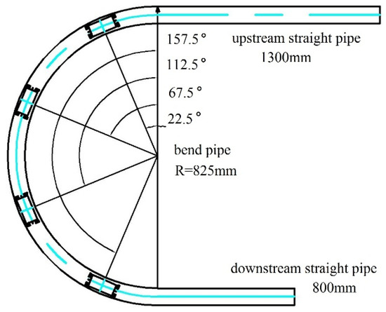
Figure 3.
Schematic diagram of starting the wheeled capsule at different positions of the bend pipe.
Table 2.
Threshold of motion Reynolds numbers for different conditions.
The upstream flow is behind the capsule, the downstream flow is in front of the capsule, and the gap flow is in the zone between the capsule wall and the pipe’s inner wall. For each condition, three analysis sections were used. The upstream section represented the upstream flow, the downstream section represented the downstream flow, and the gap section represented the gap flow. These analysis sections’ locations are shown in Figure 4.
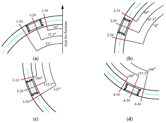
Figure 4.
Analysis section layout: (a) location θ = 22.5° (first condition); (b) location θ = 67.5° (second condition); (c) location θ = 112.5° (third condition); (d) location θ = 157.5° (fourth condition). The symbols # are the marks of sections; the red lines are the locations of sections; the blue lines are the axis of the pipeline.
3. Numerical Simulation
3.1. Simulation Domain Deployment and Mesh
The experimental data were used for the validation of numerical simulation results. The simulation domain was bounded by synthetic considerations of physical experimentation, precision of simulation, and simulation time. The simulation domain consisted of the upstream straight pipe (1.3 m in axial length), the U-type bent pipe (radius was 0.825 m and axial length was 2.6 m), and the downstream straight pipe (0.8 m in axial length). The inlet of the simulation domain was set up with pipe flow velocity distribution measured in the physical experiments, and the boundary condition was the incompressible velocity at the inlet. The outlet of the simulation domain was set up with pipe flow pressure measured by the physical experiments, the boundary condition was the pressure at the outlet. The wall of the horizontal bent pipe and the wall of the wheeled capsule both had a no-slip boundary condition. The mesh of the simulation domain could be divided into two parts. One was the structured mesh (hexahedron) away from the wheeled capsule; the other was the unstructured mesh (pyramid) for the zone near the wheeled capsule. All the mesh grids were designed by ANSYS ICEM. Figure 5 shows some of the mesh conditions.
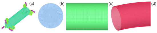
Figure 5.
Grid diagram of each part: (a) mesh of the wheeled capsule; (b) mesh of the interface between the straight and the bend pipes; (c) structured mesh of the straight pipe; (d) unstructured mesh of the bend pipe.
3.2. Turbulence Model
In the simulation studies of wheeled capsule pipeline transportation and the studies of the bent-pipe simulation, the Reynolds number of the pipe flow can be calculated by Re = ρ × V × D/μ, ρ is the density of the fluid, V is the section-averaged velocity, D is the diameter of the pipe, and μ is the dynamic viscosity. The Reynolds numbers were all more than 50,000 during the wheeled capsules’ movement initiation—notably bigger than the Laminar flow’s Reynolds number, 2320, for the pipe flow. The pipe’s flow pattern during the four conditions was fully turbulent flow. The simulation was processed with the RNG k-ε model to calculate the rotation effects of flow induced by the bend’s boundary. The fluid motion control equations were the Reynolds-averaged equation and the constant equation in the condition of an incompressible fluid.
where, ρ is the density of fluid; ui, uj are the averaged velocity components, i, j = 1, 2, 3; xi, xj are the coordinate components; μ is the dynamic viscosity; p is the pressure; ρuiuj is the Reynolds stress; u’i, u’j are the fluctuating velocity components; S is the source item.
The turbulence kinetic energy k and the turbulence dissipation rate ε are calculated by the following equations:
where v is the velocity magnitude of the pipe’s flow; I is the turbulence intensity—I = 0.16 Re−0.125; Cμ is the constant number of the model—Cμ = 0.09; l is the reference length of turbulence.
3.3. Verification of Simulation Result
The numerical simulations were processed by ANSYS FLUENT. The verification of simulation results was performed via independent verification of the mesh. The verification sections were the sections θ = 22.5°, θ = 67.5°, θ = 112.5°, and θ = 157.5°; the results are shown in Figure 6. The simulation results had a relative error of less than 3.5% with regard to the physical results when the averaged scale of the mesh was 1 mm, and the precision met the research target (relative error 3.5% < 5%). Thus, the simulations used an averaged scale of mesh of 1 mm to calculate all the conditions.
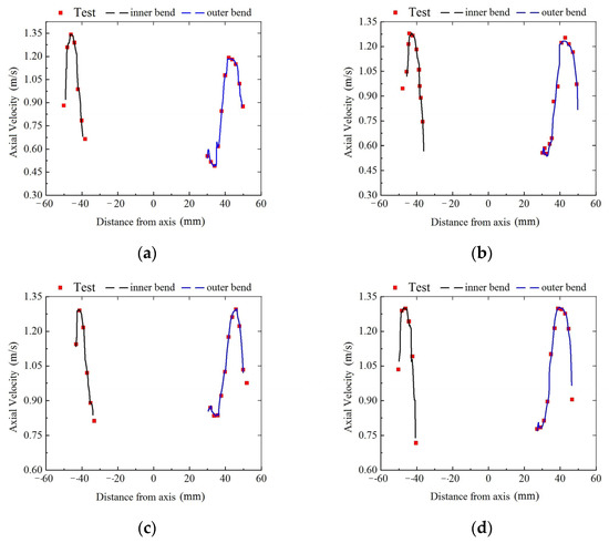
Figure 6.
Comparison of simulation results and test results of the axial velocity of gap flow: (a) first condition θ = 22.5°; (b) second condition θ = 67.5°; (c) third condition θ = 112.5°; (d) fourth condition θ = 157.5°.
4. Result and Discussion
4.1. Total Flow Distribution during Capsule Threshold of Motion
The total flow distributions of the pipelines in the horizontal plane of the pipelines’ axis are shown in Figure 7. The total flow demonstrates two patterns in Figure 7a. In the first, the flow vectors are all parallel with the axes of the pipelines. In the second, the flow illustrates a tendency of larger velocity at the outer bend zone than it at the inner bend zone. This tendency started in the bend of the pipeline and was maintained throughout the downstream straight pipe. The flow patterns in Figure 7a were caused by the bend boundary limitation of the pipe. It changed the flow direction and transmitted the influence downstream.
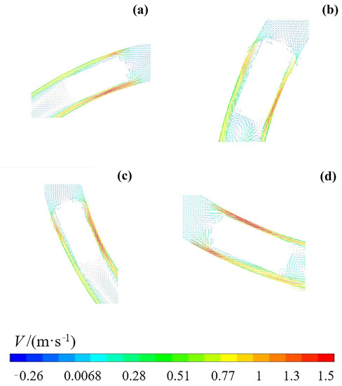
Figure 7.
The vector diagram of the water flow velocity in the XOZ plane (the horizontal plane where the pipe axis is located), the centroid of the wheeled capsule had angle locations of θ: (a) First condition θ = 22.5°; (b) Second condition θ = 67.5°; (c) Third condition θ = 112.5°; (d) Fourth condition θ = 157.5°.
As shown in Figure 7a–d, the four conditions are the positions of capsules and the total flow distributions of the pipelines were changed severely by the wheeled capsule. The changes had two influences. The first was that the velocity gradient of the gap flow between the capsule and pipe was larger than it of the pipe flow. The second was that the flow formed two backwash zones downstream of the capsule. Additionally, the two backwash zones were not symmetrical regarding the axes of the capsule, and the backwash zone was larger in the outer bend zone than in the inner bend zone, also leading to the radial velocity flowing from the outer bend to the inner bend zone.
4.2. Different Flow Distributions of the Four Threshold of Motion Conditions
4.2.1. The Axial Velocity Distribution
The axial velocity distributions of different conditions are shown in Figure 8. Upstream of the wheeled capsule, the axial velocities all followed the distribution of higher velocity in the outer bend zone and lower velocity in the inner bend zone, except the first condition (nearly symmetrical regarding the axis of the pipe). Additionally, the axial velocity got larger in the outer bend zone in all the conditions, because the flow traveled further in the bent pipeline. The effect of this limitation of the bent pipeline was critical. However, for the first condition, the flow passed only a little further in the bent pipeline, so the influence of the bent pipeline was not obvious. In the gap zone between the capsule and the pipe, the axial velocity was minor near the capsule but larger near the pipe. Additionally, the axial velocity in the outer bend zone was different from that in the inner bend zone. The flow section was small in the inner bend zone, but the velocity’s magnitude was larger, whereas the flow section was larger in the outer bend zone, but the velocity’s magnitude was smaller. There was a difference between the velocity’s magnitude in these two flow sections; the difference became larger from the first condition to the fourth condition. Downstream of the wheeled capsule, the axial velocity was minor near the axis, even negative, and the velocity was larger near the pipe. This was because of the existence of backwash zones. The backwash zones transport the flow from the pipe wall to the axis of the pipe. Additionally, there was no obvious difference between the conditions. This meant that the blockage effect of the capsule weakened the asymmetry of the bent pipeline.
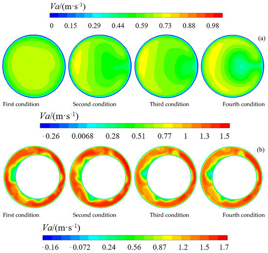
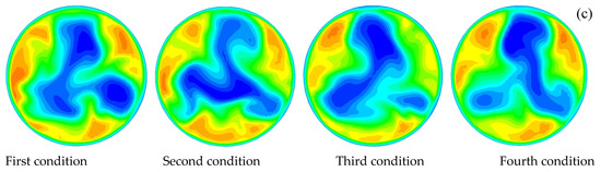
Figure 8.
The axial flow velocity distribution cloud map of the characteristic section when the pipeline truck starts at different positions of the pipe bend (the conditions meaning the centroid of the wheeled capsule had angle locations of θ): (a) upstream of the wheeled capsule; (b) gap zone between the capsule and the pipe; (c) downstream of the wheeled capsule.
4.2.2. The Radial Velocity Distribution
In the radial velocity distributions of the four conditions in Figure 9, the radial transmission of the flow is demonstrated. In summary, the radial velocity was larger upstream of the capsule than downstream. With the capsule in the same location, the radial velocity was larger in the whole bent pipe, both upstream and downstream. Upstream of the capsule, the velocity magnitude was larger in the outer bend zone than in the inner bend zone. In the gap zone between the capsule and the pipe, the radial velocity of the inner bend zone was larger than that of the outer bend zone. However, downstream of the capsule, the radial velocity showed no difference between the inner bend zone and the outer bend zone. The blockage effect of the capsule made the radial flow more even downstream of the capsule.
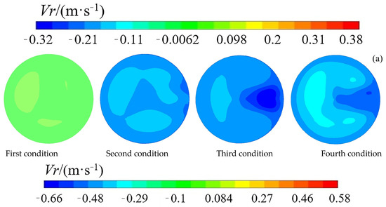
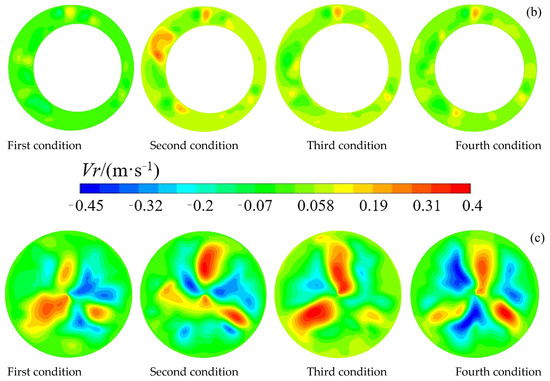
Figure 9.
The radial flow velocity distribution cloud map of the characteristic section when the pipeline truck starts at different positions of the pipe bend (the conditions meaning the centroid of the wheeled capsule had angle locations of θ): (a) upstream of the wheeled capsule; (b) gap zone between the capsule and the pipe; (c) downstream of the wheeled capsule.
4.2.3. The Circular Velocity Distribution
The circular velocity distribution of the four conditions in Figure 10 can provide some information about the transmission style of the sections. Upstream of the capsule, the circular velocity was negative near the pipe wall in the upper parts of the sections, and the circular flow direction pointed upstream via a right-handed helix. The circular velocity was positive near the pipe wall in the lower parts of the sections. This meant the flow direction pointed downstream via a right-handed helix. Additionally, in the middle parts of the sections, both the upper-half and the lower-half flow direction are pointed upstream via a right-handed helix. For the gap zone, the sections had narrow circular flow, and the velocity was lower (close to zero) than in other locations. The flow of the gap zone was stable and less circular. Downstream of the capsule, because of the effect of the flow in the bend, the circular velocity was larger than in other locations. The circular velocity distribution in the third condition was the most uneven, followed by the fourth condition and the second condition. The first condition had the most even distribution. The distribution of circular velocity was caused by the centrifugal transmission of the pipe flow. The flow had a tendency to travel from the inner bend to the outer bend. The outer-bend flow was pressed by the inner-bend flow.
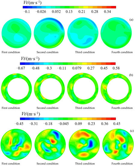
Figure 10.
The circumferential flow velocity distribution cloud map of the characteristic section when the pipeline truck starts at different positions of the pipe bend (the conditions meaning the centroid of the wheeled capsule had angle locations of θ): (a) upstream of the wheeled capsule; (b) gap zone between the capsule and the pipe; (c) downstream of the wheeled capsule.
4.3. Theory Analysis
The wheeled capsule itself in mechanical models is often considered as a whole part, a rigid body [5,10,17]. The friction forces of the four bolsters can be handled as one friction force acting on the centroid of the wheeled capsule. However, this consideration of the friction forces is only suitable for symmetry boundaries, as in the horizontal straight pipe; see Figure 11a. For the horizontal bent pipe, we can distinguish the inner boundary and the outer boundary, so the boundary conditions of the bent pipe are asymmetric; the combined friction force mentioned above is not suitable for a wheeled capsule in a bent pipe.
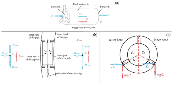
Figure 11.
The mechanics schematic of wheeled capsule: (a) schematic of the wheeled capsule in straight pipe; (b) schematic of the wheeled capsule in bend pipe; (c) asymmetry force condition of wheeled capsule in bend pipe. The red vectors are the equivalent forces of surface stress; the blue vectors are the concentrate forces.
From the results shown in Section 4.2, it is obvious that the upstream flow demonstrates the tendency that the velocity in the outer bend is not equal to the velocity in the inner bend. This means that the forces induced by the bent pipe’s water flow acting on the wheeled capsule are not even between the inner bend and the outer bend; the water flow’s asymmetry close to the wheeled capsule is the consequential factor.
The boundary condition’s asymmetry and the water flow’s asymmetry in the horizontal plane of a bent pipe make the previous mechanical models of a wheeled capsule in a straight pipe not suitable for the wheeled capsule’s threshold of motion problem in a horizontal bent pipe.
A new mechanical model of a wheeled capsule in a horizontal bent pipe is proposed, as shown in Figure 11b. We can consider that the wheeled capsule is divided into two parts; the two parts have equal mass and symmetrical shapes. There are two centroid points for the two parts: point C1 is the centroid of the outer part, and point C2 is the centroid of the inner part. The external forces acting on the wheeled capsule are the pressure drag force DP, the friction drag force DF, and the additional pressure drag force DA. The friction drag force is the friction force of the water flow acting on the flank of the cylindrical container. The pressure drag force is the pressure difference between the backward surface and the forward surface; its direction is perpendicular to the surface. An additional pressure drag force emerges with the centrifugal effect of the water flow acting on the wheeled capsule in the bent pipe; its direction is radial from the inner bend to the outer bend. At the same time, the friction drag force is always parallel with the wall causing it, so there is no additional friction drag force [16]. The drag forces are fluid dynamical forces and are only related to the shape of the wheeled capsule, so they can be divided into two parts acting on the two centroids individually.
As it is shown in Figure 11c, because the additional pressure drag force is always perpendicular to the acting surface, the external forces make the forces of the two parts of the capsule not symmetrical, the bolsters of the outer part have more pressure than those of the inner part on the pipe wall.
Then the balance condition of the inner part and the outer part of the wheeled capsule can be described as:
The balance of the whole wheeled capsule can be interrupted by the instability of each part. As the formula demonstrates, the maximum static friction of the inner part is lower than it of the outer part, so the interruption of the balance of the wheeled capsule begins from the inner part. Furthermore, the threshold of motion of the wheeled capsule in the straight pipe is the special condition of it in the bend pipe (DA = 0). Therefore, the drag forces have such an order that the drag force of the inner part’s instability of the bend pipe is minor then the drag force of the outer part’s instability, and the instability of the straight pipe is between them for the same wheeled capsule:
To conclude, this mechanical model can explain the results of the physical experiment: the wheeled capsule is easier to get moving in a bent pipe than in a straight pipe. All of the above deductions form the mechanical model for wheeled-capsule threshold of motion in a horizontal bent pipe.
5. Conclusions
(a) Regarding the energy consumption of the wheeled capsules’ threshold of motion, the wheeled capsule was easier to threshold of motion in the bent pipe than it in the straight pipe. The wheeled capsule’s threshold of motion had lower energy consumption in the bent pipe, for the water flow had lower energy at smaller Reynolds numbers. Regarding the velocity field of the flow, the velocity of the water flow was different in the inner part and the outer part of the section close to the wheeled capsule. This was unlike the water flow of the section in the straight pipe.
(b) A new view was proposed to explain the easier threshold of motion of the capsule in the bent pipe by dividing the wheeled capsule into two parts. The external forces were described as the pressure drag force, the friction drag force, and the additional pressure drag force. The deductions showed that the bolsters of the inner part of the wheeled capsule in the bent pipe endured less maximum static friction than in the straight pipe. The whole wheeled capsule was more unstable in the bent pipe than in the straight pipe because of the additional drag force induced by the centrifugal effect of the bent pipe’s water flow.
Author Contributions
Data curation, Y.L. and Y.Z.; Funding acquisition, X.S.; Investigation, Y.L., Y.Z., Y.Y. and Y.T.; Writing—original draft, Y.L.; Writing—review and editing, X.S. All authors have read and agreed to the published version of the manuscript.
Funding
The research was funded by the National Natural Science Foundation of China (51179116).
Institutional Review Board Statement
Not applicable.
Informed Consent Statement
Not applicable.
Data Availability Statement
This research was supported by the Collaborative Innovation Center of New Technology of Water-Saving and Secure and Efficient Operation of Long-Distance Water Transfer Project at the Taiyuan University of Technology.
Acknowledgments
The research was supported by the Collaborative Innovation Center of New Technology of Water-Saving and Secure and Efficient Operation of Long-Distance Water Transfer Project at Taiyuan University of Technology.
Conflicts of Interest
The authors declare no conflict of interest. The funders had no role in the design of the study; in the collection, analyses, or interpretation of data; in the writing of the manuscript; or in the decision to publish the results.
References
- Minh, A.; Samudrala, S.; Bhattacharya, S. Valorisation of glycerol through catalytic hydrogenolysis routes for sustainable production of value-added C3 chemicals: Current and future trends. Sustain. Energ. Fules 2022, 6, 596–639. [Google Scholar] [CrossRef]
- Paul, A.; Bhattacharyya, S. Analysis and Design for Hydraulic Pipeline Carrying Capsule Train. J. Pipeline Syst. Eng. 2021, 2, 04021003. [Google Scholar] [CrossRef]
- Li, Y.; Sun, X.; Zhang, X. Study of the energy consumption of the piped vehicle hydraulic transportation. Adv. Mech. Eng. 2019, 11, 168781401988554. [Google Scholar] [CrossRef]
- Li, Y.; Gao, Y.; Sun, X.; Zhang, X. Study on Flow Velocity during Wheeled Capsule Hydraulic Transportation in a Horizontal Pipe. Water 2020, 12, 1181. [Google Scholar] [CrossRef]
- Jia, X.; Sun, X.; Song, J. Effect of Concentric Annular Gap Flow on Wall Shear Stress of Stationary Cylinder Pipe Vehicle under Different Reynolds Numbers. Math. Probl. Eng. 2020, 2020, 1253652. [Google Scholar] [CrossRef]
- Ulusarslan, D. Experimental investigation of the effect of diameter ratio on velocity ratio and pressure gradient for the spherical capsule train flow. Eur. J. Mech. B-Fluid 2013, 37, 42–47. [Google Scholar] [CrossRef]
- Teke, I.; Ulusarslan, D. Mathematical expression of pressure gradient in the flow of spherical capsules less dense than water. Int. J. Multiph. Flow 2007, 33, 658–674. [Google Scholar] [CrossRef]
- Asim, T.; Mishra, R. Computational fluid dynamics based optimal design of hydraulic capsule pipelines transporting cylindrical capsules. Power Technol. 2016, 295, 180–201. [Google Scholar] [CrossRef]
- Asim, T.; Mishra, R. Optimal design of hydraulic capsule pipelines transporting spherical capsules. Can. J. Chem. Eng. 2016, 94, 966–979. [Google Scholar] [CrossRef]
- Li, Y.; Sun, X. Mathematical Model of the Piped Vehicle Motion in Piped Hydraulic Transportation of Tube-Contained Raw Material. Math. Probl. Eng. 2019, 2019, 3930691. [Google Scholar] [CrossRef]
- Li, Y.; Sun, X.; Zhang, X. Experimental study of the wheeled capsule motion inside hydraulic pipeline. Adv. Mech. Eng. 2019, 11, 168781401984406. [Google Scholar] [CrossRef]
- Zhang, X.; Sun, X.; Li, Y.; Xi, X.; Guo, F.; Zheng, L. Numerical investigation of the concentric annulus flow around a cylindrical body with contrasted effecting factors. J. Hydrodyn. 2015, 27, 2273–2285. [Google Scholar] [CrossRef]
- Liu, H.; Graze, H.R. Lift and Drag on Stationary Capsule in Pipeline. J. Hydraul. Eng. 1983, 109, 28–47. [Google Scholar] [CrossRef]
- Yu, L. Incipient Motion of Static Material-logs in Slurry Pipeline. Mech. Eng. 2002, 24, 20–23. (In Chinese) [Google Scholar]
- Sun, X.; Li, Y.; Yan, Q. Experimental study on starting conditions of the hydraulic transportation on the piped carriage. In Proceedings of the 20th National Conference on Hydrodynamics, Beijing, China, 23–25 August 2007. [Google Scholar]
- Yang, X.; Ma, J.; Li, Y.; Sun, X.; Jia, X.; Li, Y. Wall Stresses in Cylinder of Stationary Piped Carriage Using COMSOL Multiphysics. Water 2019, 11, 1910. [Google Scholar] [CrossRef]
- Jia, X.; Sun, X.; Li, Y. Numerical Simulation of the Flow Field Characteristics of Stationary Two-Pipe Vehicles under Different Spacings. Water 2020, 12, 2158. [Google Scholar] [CrossRef]
- Zhang, C.; Sun, X.; Li, Y.; Zhang, X.; Zhang, X.; Yang, X.; Li, F. Effects of Guide Vane Placement Angle on Hydraulic Characteristics of Flow Field and Optimal Design of Hydraulic Capsule Pipelines. Water 2018, 10, 1378. [Google Scholar] [CrossRef]
- Zhao, Y.; Li, Y.; Song, X. PIV Measurement and Proper Orthogonal Decomposition Analysis of Annular Gap Flow of a Hydraulic Machine. Machines 2022, 10, 645. [Google Scholar] [CrossRef]
- Sigalotti, L.D.G.; Alvarado-Rodríguez, C.E.; Klapp, J.; Cela, J.M. Smoothed Particle Hydrodynamics Simulations of Water Flow in a 90° Pipe Bend. Water 2021, 13, 1081. [Google Scholar] [CrossRef]


Publisher’s Note: MDPI stays neutral with regard to jurisdictional claims in published maps and institutional affiliations. |
© 2022 by the authors. Licensee MDPI, Basel, Switzerland. This article is an open access article distributed under the terms and conditions of the Creative Commons Attribution (CC BY) license (https://creativecommons.org/licenses/by/4.0/).