Article

Model Experiment Exploration of the Kinetic Dissipation Effect on the Slit Dam with Baffles Tilted in the Downstream Direction

1
School of Civil Engineering and Transportation, South China University of Technology, Guangzhou 510640, China
2
State Key Laboratory of Subtropical Building Science, South China University of Technology, Guangzhou 510640, China
*
Authors to whom correspondence should be addressed.
Water 2022, 14(18), 2772; https://doi.org/10.3390/w14182772
Submission received: 13 July 2022 / Revised: 15 August 2022 / Accepted: 2 September 2022 / Published: 6 September 2022
(This article belongs to the Section Hydraulics and Hydrodynamics)

Abstract

:
Slit dams can eliminate the risk of particle overload accumulation, which can be safer in controlling debris flow compared with a completely closed dam. In attempting to better use the energy dissipation effect of particle collision and reduce the impact of the dam body, referring to the traditional slit dam, this paper proposed one with tilted baffles in the downstream direction. Discrete element simulation and several flume model experiments were carried out herein to verify the advantages and explore the applicable conditions of this tilted baffle slit dam, in which the particle trapping efficiency and the change law of impact force of the tilted baffles under the conditions of different inclined angles, opening sizes, and particle sizes were studied. The results show that: 1. when the inclination angle is 30° ≤ θ ≤ 45°, the tilted baffles can dissipate more particle kinetic energy than the transverse baffles; 2. the maximum impact force and trapping efficiency of the tilted baffles decrease with the increase in the width diameter ratio b/d, with the opening width b of the slit to the particle diameter d; 3. with the given particle size of 6 mm ≤ d ≤ 14 mm, the range that the tilted baffles can effectively intercept the particles flowing down is 0 ≤ b/d ≤ 4, and it reaches the ideal interception state near 1 ≤ b/d ≤ 2, where, relatively, the impact force is weak, and the interception efficiency is high.

1. Introduction

Debris particles in mountain debris flow often contain huge kinetic energy, causing great harm to the safety of buildings, roads, people, and property in mountainous areas [1,2]. To prevent and control this natural disaster, a variety of measures have been practiced, such as rigid barriers [3,4,5,6,7,8], flexible barriers [9,10,11,12,13], and barrier arrays [14,15,16]. Among them, rigid barriers (including check dams and slit dams) are widely used. To guide these practical projects, many scholars have conducted in-depth research on the interaction between particles and rigid barriers [17,18,19,20,21,22,23,24,25,26].
The rigid barrier mainly intercepts the dry particle flow by blocking the flow with its body. Therefore, the impact force of particles on the rigid barrier is the most direct index to evaluate the interaction between the particle and the barrier. Jiang YJ has done a series of research work on this, such as the empirical analysis of the impact force of dry particles during the particle flow avalanche of indoor model experiments [27,28,29]; the subsequent work involved the influence of particle size on the impact force studied using the DEM method [30], and the semi-empirical calculation formula proposed for the impact force of dry particle flow [31]. Compared with the completely closed check dam, the slit dam allows the accumulated particles to move downstream, eliminating the risk of particle overload damaging the dam, which can reduce the preventive maintenance cost of the structure and help to regulate the flow [32], making the management of dry particle flow more flexible and convenient. Therefore, it has received a lot of attention in research. Choi [33] and Goodwin [34] used glass ball particles as materials to study the impact force and trapping efficiency of particles under different conditions through flume experiments. It was found that the arching characteristics of particles played an important role in the process of the particle blockage of granular slit dams, which was also confirmed by the simulation study by Marcelli [35] on the interception efficiency of particles by slit dams. At the same time, some scholars [36,37,38,39] found that the collision and friction among particles and between particles and baffles can effectively dissipate the impact energy of dry particle flow, which can reduce the impact force of particles on the retaining structure and control disaster losses.
The above-mentioned studies on slit dams mostly adopt the transverse baffle structure. In contrast, to increase the collision effect between particles and baffles, a tilted baffle structure with different plane layouts is proposed in this paper. Through two-dimensional DEM simulation, the differences in particle impact velocity, system kinetic energy, the number of contacts between particles, and the maximum impact force in baffle structures with different inclined angles θ are compared. It is found that with θ between 30° and 45°, the baffle bears less particle impact force and has better particle kinetic energy dissipation performance. In addition, according to the simulation results, the flume model experiment with tilted baffles set in the downstream direction was carried out, in which the impact force and particle trapping efficiency of the dry particle flow with different particle sizes on the 45° inclined baffle under various opening widths were measured. In addition, the interception performance of the inclined baffle was evaluated through the trapping impact force (a combined factor to evaluate both the impact force and the interception efficiency). This study can deepen the understanding of the interaction between dry particle flow and baffle structure and provide new insights for mitigating debris flow disasters.

2. Materials and Methods

The discrete element method can accurately monitor the energy, velocity, and other key variables of moving particles and can play an important role in the analysis of the interaction between particles and baffles. Therefore, it is widely used in studying the impact process of dry particles [39,40,41]. Herein, the discrete element method was adopted to study the particle impact on baffle structures with different inclined angles, in which the particle velocity, system kinetic energy, contact number between particles, and the maximum impact force were obtained. According to the simulation results, the optimal inclined angle was selected to design the flume experiments. Subsequently, in the experiment, the particle impact force and interception efficiency of the inclined baffle structures with various opening widths and particle sizes were studied.

2.1. DEM Method

The DEM method adopted here is mainly used to qualitatively demonstrate the kinetic energy dissipation effect of the tilted baffle structure on the particle flow system. To better understand the energy dissipation caused by this tilted baffle structure, the disturbance of the bottom plate of the flume should be excluded. Therefore, a two-dimension model was conducted for studying the influence of different baffle angles on the particle system. With the guidance of the simulation results, an optimal lined angle of the baffle was then selected for the flume model experiment.

2.1.1. Numerical Simulation Model

To compare the effects of baffle structures with different inclined angles on dissipating particle kinetic energy during the particle flow impact, as shown in Figure 1a, baffle structure models with inclined angles of 0°, 15°, 30°, and 45° were established. The flume, with a width of w = 250 mm, was tightly stacked with 2200 spherical particles (diameter d = 10 mm) on the top, and the height of the transverse partition below the particles from the bottom of the flume was h = 1400 mm. When the transverse clapboard disappeared, the particles moved downward under the action of gravity and impacted the bottom of the flume.

2.1.2. Parameters and Process of DEM

To make the simulation results more credible, some parameters used in the simulation were selected referring to similar research [42], while the rest of the parameters were obtained through measurement, as shown in Table 1. When the DEM method was used for simulation, as shown in Figure 1a, firstly, the particles were closely stacked and held by a transverse baffle at a height of 1400 mm from the flume bottom, and then the transverse baffle was removed to let the particles fall naturally under the action of gravity until the particles were stably stacked at the bottom of the flume. During the dropping and the impact of the particles, the particle velocity, the kinetic energy of the particle system, the number of contacts between the particles, and the maximum impact force of the particles on the baffle were recorded.

2.2. Flume Experiment

To explore the interaction between inclined baffle structure and dry particle flow, the impact force and trapping efficiency of particle flow with different particle sizes on a 45° inclined baffle structure were studied using flume experiments under the conditions of various slit widths and openings.

2.2.1. Experimental Device

The experiment was carried out in the flume device as indicated in Figure 1b. The flume was made of PVC material with side walls of height h = 200 mm, the width w = 250 mm, and a total length of L = 2100 mm, and erected at an angle of 20° with the ground. As indicated in Figure 1b,c, a door plate was placed 300 mm from the flume top for storing spherical glass particles. The door plate could be bolted by the side wall and pulled out to release the stored glass spherical particles. As shown in Figure 1d, the inclined baffle was installed on the side wall 400 mm away from the bottom of the flume through hinges. According to the reference [8], the maximum impact force in the traditional slit dam occurred at both sides of the slit opening. Therefore, a pressure sensor was set at the end of the baffle along the normal direction of the baffle, with a range of 0~10 N and a measurement accuracy of 0.01 N so that the normal impact force on the baffle could be measured during the movement of particles. According to the simulation results, the included angle between the inclined baffle and the side wall was fixed at θ = 45°, and the slit width b was controlled within the range of 0~40 mm by changing the baffle lengths.

2.2.2. Experiment Particles

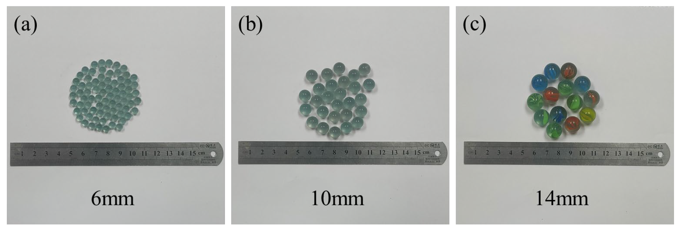
Glass balls have clear characteristic grain diameter and good uniformity. To study the influence of different particle sizes on the impact behavior, as in Figure 2, glass ball particles with diameters d = 6 mm, 10 mm, and 14 mm were used in this experiment. The properties of the glass balls are shown in Table 2.

2.2.3. Experimental Steps

In this study, a series of flume experiments were carried out on inclined baffle structures with different opening slit widths using particles with the same mass and different particle sizes. The detailed experiment conditions are given in Table 3. As in Figure 1c, for each parallel experiment, particles with a mass of mtotal = 1.5 kg were first naturally stacked on top of the flume and then released under gravity until the particles were completely stationary; the normal force on the inclined baffle during each parallel experiment was recorded using the pressure sensor with 0.2 s time interval. After each release, the particle mass trapped by the inclined baffle was recorded as mtrap. Each experiment combination was measured at least 3 times until the deviation of the recorded impact force was less than 10%.

3. Results

3.1. DEM Simulation Results

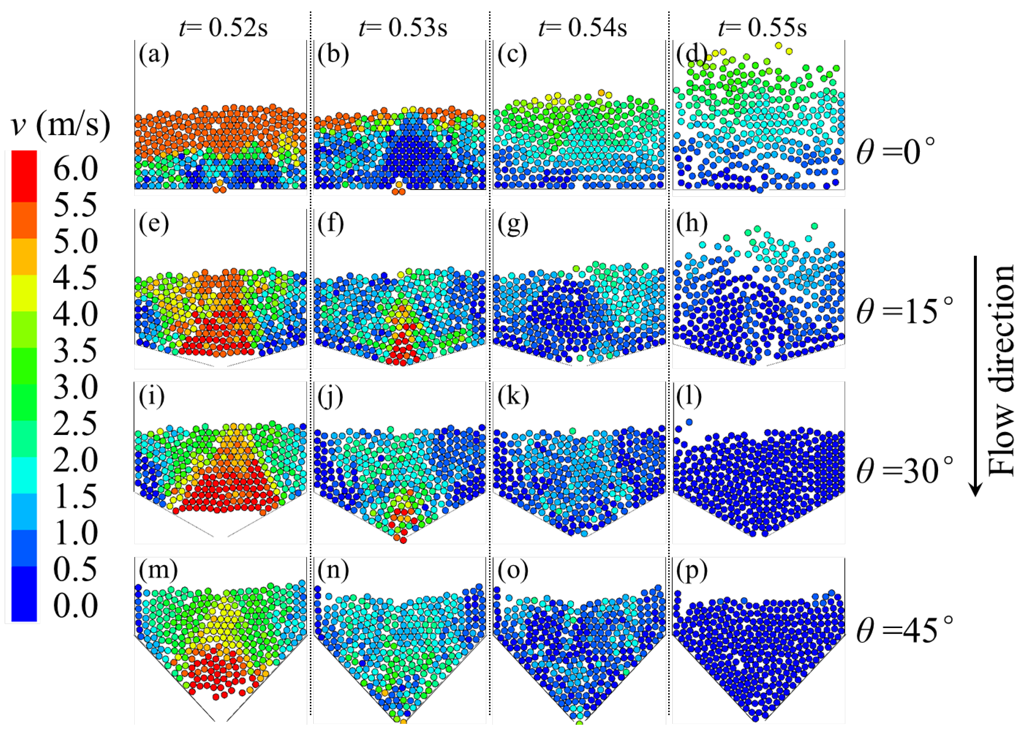
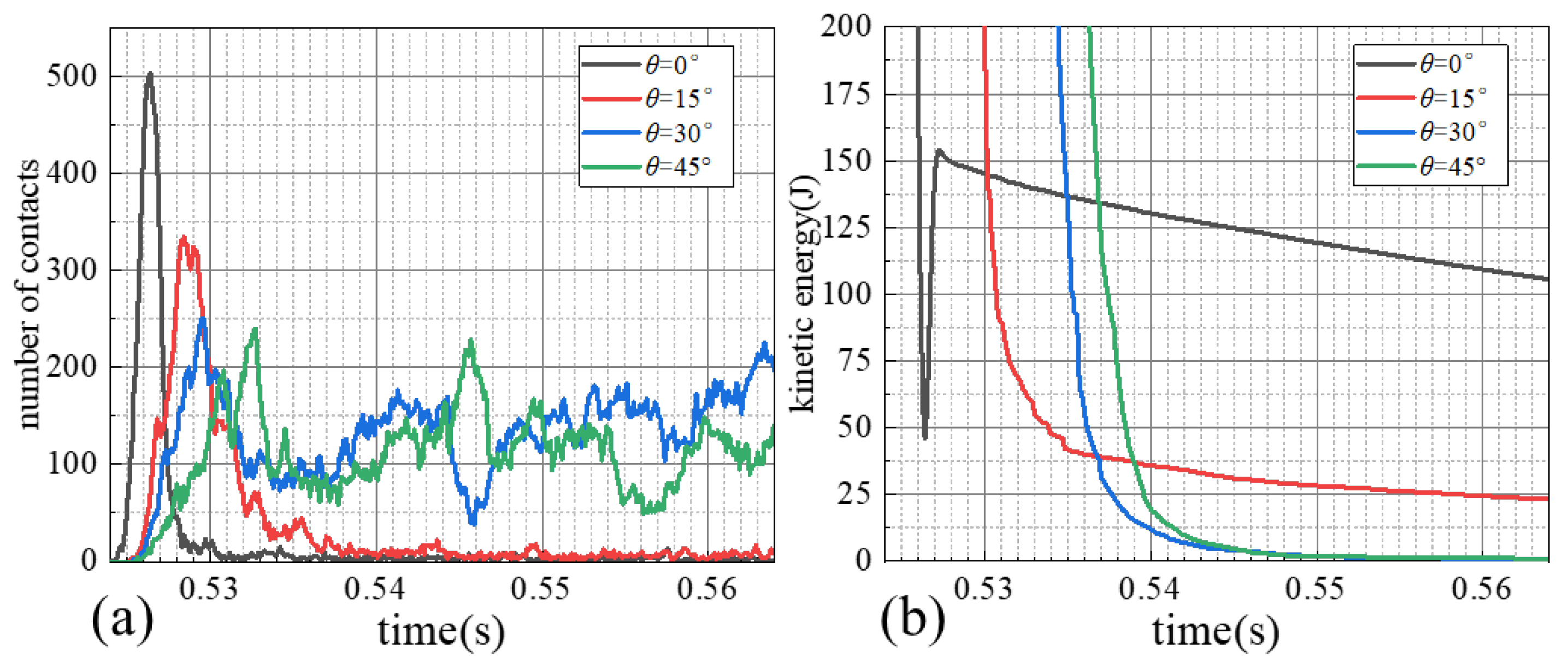
The velocity changes of particles impacting the baffle structure with different inclined angles θ obtained from the DEM simulation are shown in Figure 3. At time t = 0.52 s, the particles began to contact the baffle; the particle velocity changed, but the particle velocity distributions within the baffles with different inclination angles were different. In the baffle structure with inclination angle θ = 0°, the maximum velocity of the particles first appeared in the upper part of the particle group and then decayed downward layer by layer, with the velocity decay direction perpendicular to the baffles. While in the other baffle structures where θ was not 0°, the maximum velocity of the particles was concentrated in the middle part of the particle group and gradually converged downward with the increase of θ; the velocity decay direction was parallel to the baffle structure. At t = 0.53 s, as the particles continued to move downward, the overall velocity of the particles in all baffles significantly decreased. Combining Figure 4a,b, it can be found that in the time period of t = 0.525 s~0.535 s, the number of contacts between particles in all baffle systems greatly increased, and the kinetic energy of the system rapidly decayed.
From t = 0.54 s, the difference in the energy dissipation of the four baffle structures on particles was gradually becoming more obvious; the contact number of particles in the θ = 0° and θ = 15° baffles rapidly decreased to nearly zero, while the contact number in the θ = 30° and θ = 45° baffles remained at the original level. Meanwhile, the kinetic energy of the system was opposite to the changing trend of contact numbers; the kinetic energy of the system slowly decreased in the θ = 0° and θ = 15° baffles, while it rapidly decreased to zero in the θ = 30° and θ = 45° baffles. Corresponding to t = 0.54 s in Figure 3, at this time, the particles have completed the impact collision on the baffle structure. In the baffle structure θ = 0° and θ = 15°, the particles located at the upper part of the particles rebounded and moved upward and diffused, so the collisions between particles were reduced and the kinetic energy dissipation was slow. However, in the baffle structures θ = 30° and θ = 45°, the particles located at the upper part of the particle group did not rebound and diffuse upward; the particles made full contact and collided with each other, so the overall kinetic energy dissipation of particles was more significant. Therefore, when t = 0.55 s, the particles in the baffle structures with θ = 30° and θ = 45° were almost stationary, while some particles in the baffle structures with θ = 0° and θ = 15° were still in diffusion motion.
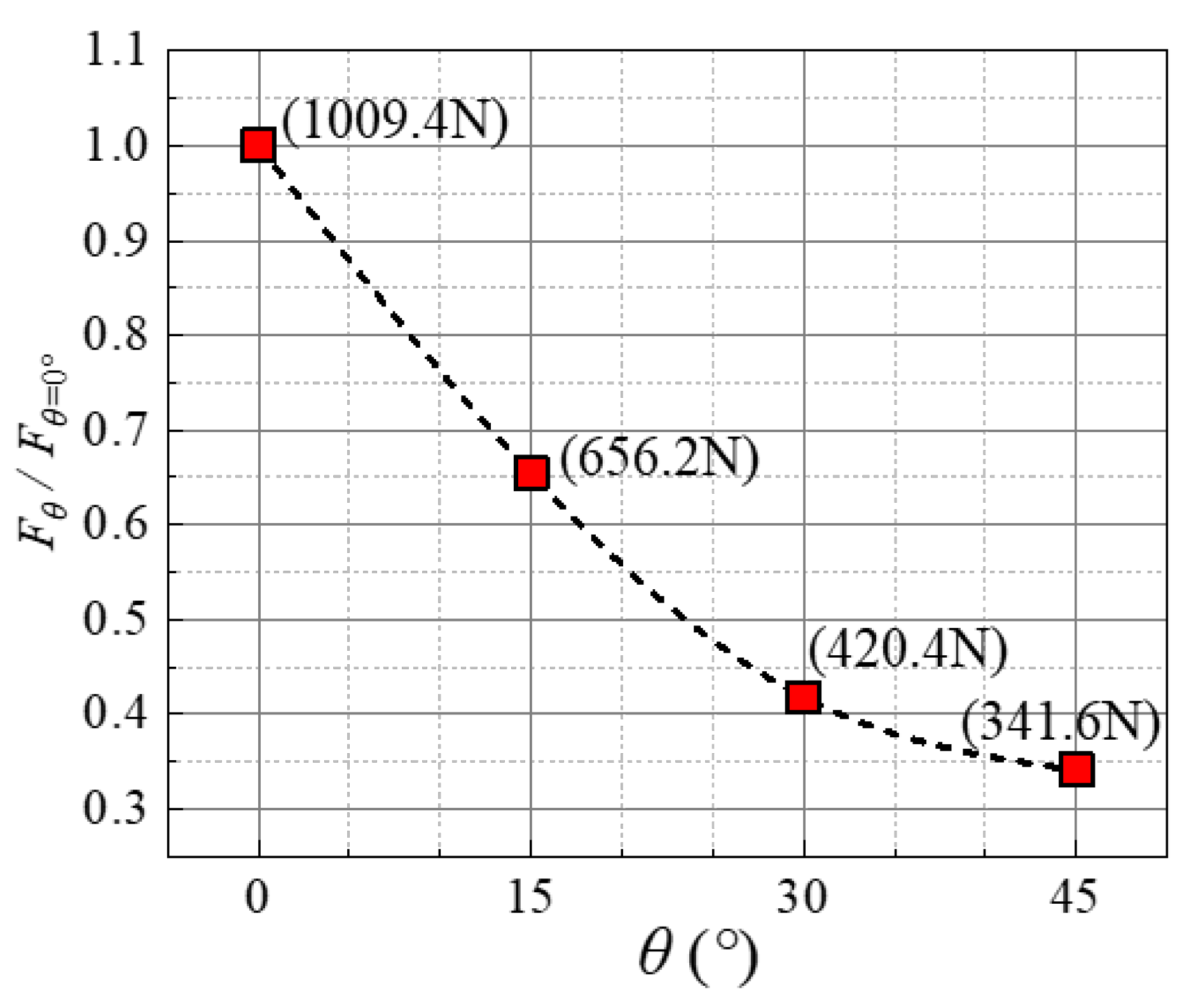
Figure 5 depicts the normalized results of the maximum impact force on baffles with different inclined angles during the particle impact; the ordinate Fθ=0° in the figure is the maximum impact force on baffles with θ = 0°. With the increase of θ, the maximum impact force on the baffle gradually decreased. When θ ≥ 30°, the maximum impact force on the baffle could be kept at a low level. Based on Figure 3, it can be found that with the same opening width, increasing θ can delay the impact of particles on the baffle and increase the collisions and frictions among particles at the same time, which may be a factor to reduce the maximum impact force of particles on the baffle. Therefore, considering the kinetic energy dissipation performance of the particle system and the maximum impact force on baffles, a θ = 45° baffle structure was selected for the flume experiment.

3.2. Experimental Results of the Particle Impact Force

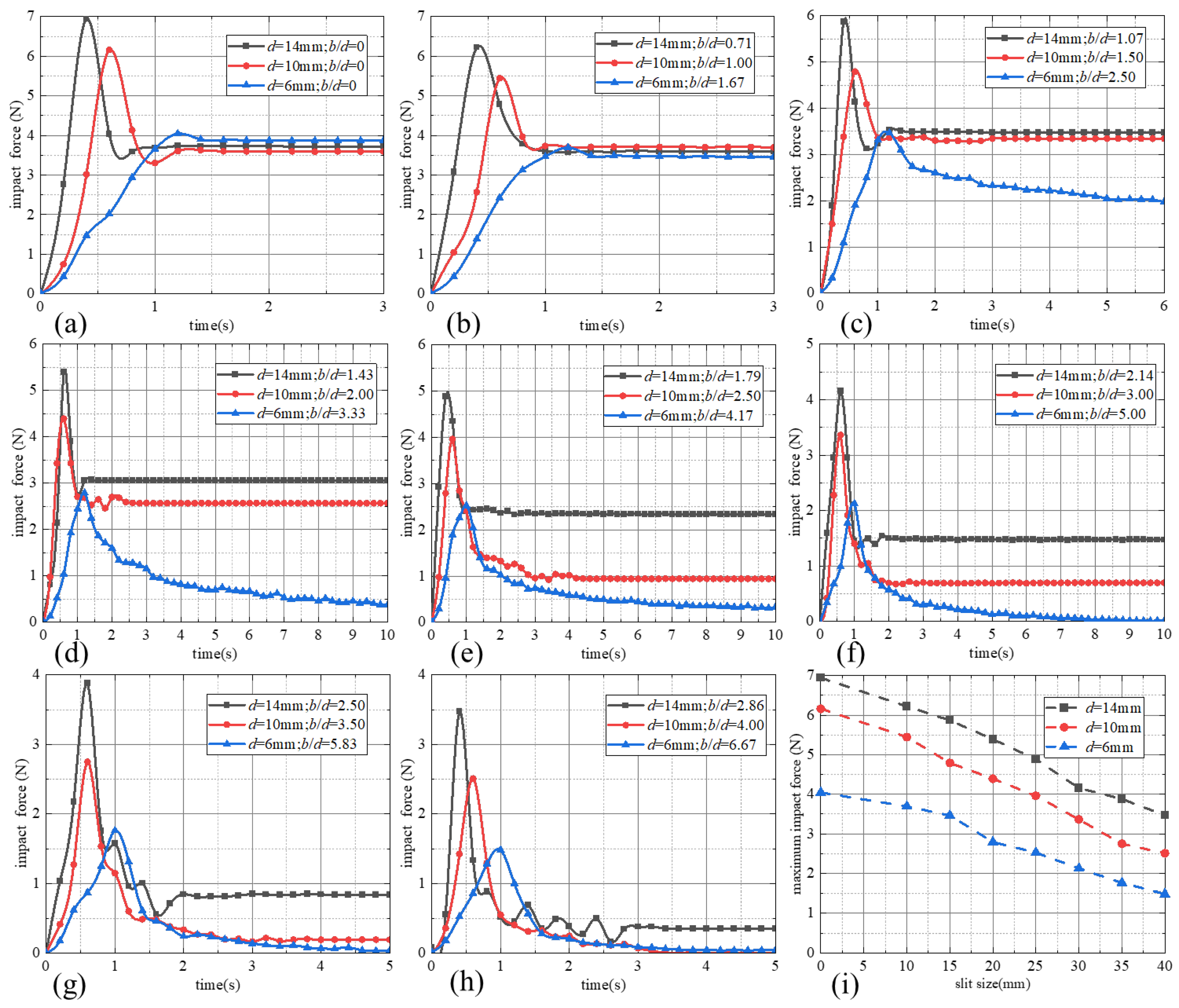
Figure 6a–h contains the experimentally measured impact force-time curve of the θ = 45° inclined baffle structure with different slit opening widths after the initial contact of the particles and the baffle structure. All impact force curves share similar change laws; that is, the peak impact force is quickly reached at first, and then it decreases until it reaches a stable value or zero. As in Figure 6i, under the same slit opening width, the larger the particle size is, the larger the impact force peak is; with the increase of the slit opening width, the peak value of the impact force on the baffle structure of each size of particle gradually decreases according to an approximately linear change. Under the condition of different opening widths, the impact force time history curve of the same kind of particles after the peak value of impact force is also different. As an example, take the d = 10 mm particles when the ratio of the slit opening width to the particle size b/d ≤ 2 (as in Figure 6a–d), the impact force (4.5~6 N) rapidly decreases to the stable value (2.5~3.5 N) within about 0.4~0.6 s after the peak appears, and the decay rate is about 4~5 N/s. However, when b/d ≥ 2, the particle impact force slowly decreases, lasting about 3~4 s after the peak value (2.5~4 N) until it reaches a stable value (0~1 N), and the decay rate is about 0.83~1 N/s, as in Figure 6e–h. While the impact time history curves of the other two sized particles also have the same change patterns, the change regularity can be explained by the different arching stability [36,37] caused by the different width diameter ratios b/d.

3.3. Experimental Results of the Trapping Efficiency

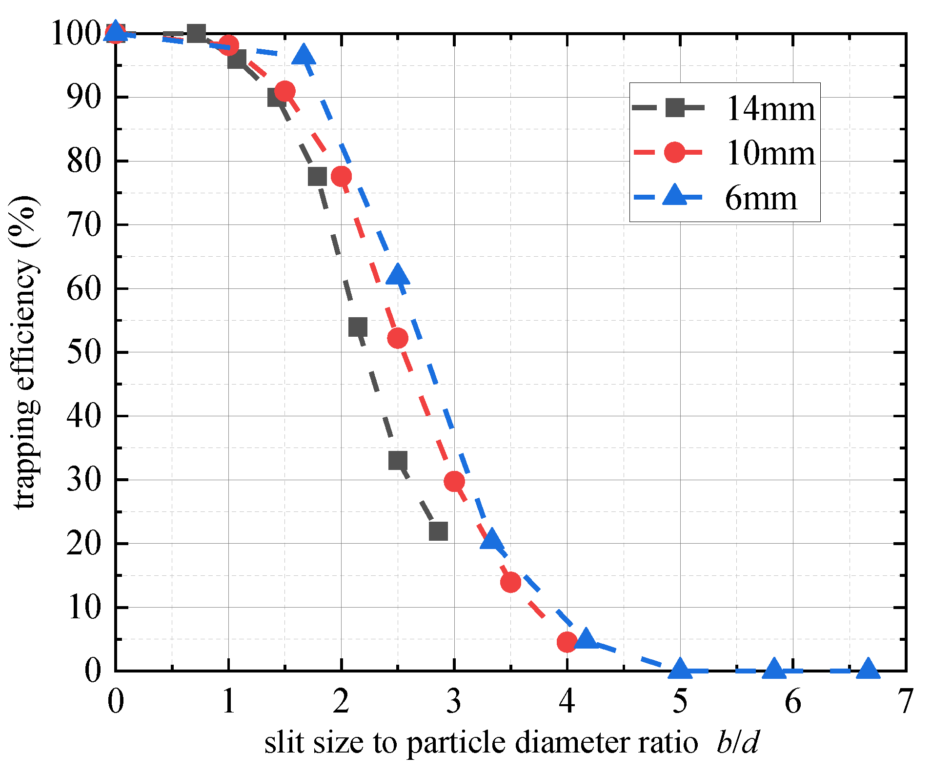
Figure 7 depicts the trapping efficiency of the θ = 45° baffle structure with different slit opening widths for different size particles, where the trapping efficiency E is expressed by Equation (1):
E =   m trap   m total
Herein, mtrap and mtotal are, respectively, the mass of particles intercepted by the baffle structure and the total mass of particles, where mtrap takes the average value of multiple stable results.
It can be seen from the figure that the trapping efficiency curve of the inclined baffle structure for the three particle sizes has the same change pattern; that is, as the ratio b/d of the slit opening width to the particle size increases, E gradually decreases according to the nonlinear change. Taking d = 10 mm particles as an example, when b/d increases from 0 to 2, E decreases from 100% to 80%; when b/d increases from 2 to 4, E decreases from 80% to 5%. It can be seen from the d = 6 mm result that when b/d ≥ 5, E = 0, i.e., the interception fails, and the number of trapped particles is zero. Under the same relative opening width b/d, the trapping efficiency E of small size particles is slightly larger than that of larger size particles because the smaller particles have less kinetic energy in the flow direction and thus are more likely to form an arching structure of particles. In combination with the change in the impact force (when stable) in Figure 6 and the trapping efficiency E in Figure 7, it can be found that during the impaction, when the ratio b/d ≤ 2, the particles are compressed and compacted by the gravity of the upper particles, which makes it easier to form a stable arch structure over the slit [33], resulting in the stopping of the particle flow and a fully blocked state in the baffle structure. When the ratio b/d ≥ 2, with the increase of the slit width, the arch structure formed by particles at the slit opening becomes unstable and tends to be damaged under the impact of external particles, resulting in a semi-blocked or non-blocked state in the baffle structure.

4. Discussion

4.1. Influence of Baffle Inclination Angle θ on Particle Kinetic Energy Dissipation (DEM Simulation)

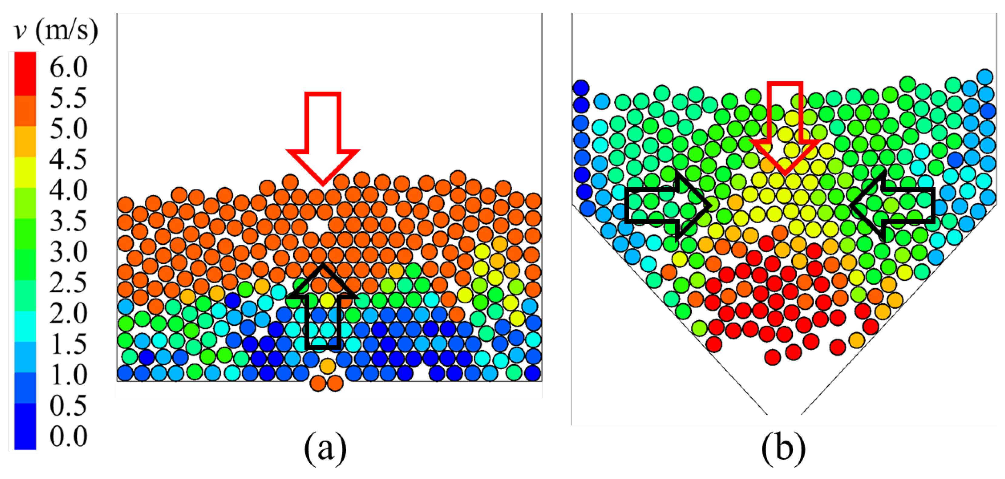
As can be seen from reference [27], when other conditions are the same, impact velocity determines the impact force of particles on the baffle structure so enhancing the kinetic energy dissipation of particles is the key to weakening the impact effect. The DEM simulation results of Figure 3 and Figure 4b indicate that under the same particle properties and baffle projected area, the baffle structure has a better particle kinetic energy dissipation effect when θ ≠ 0°, and the kinetic energy dissipation efficiency will be higher for larger angle (θ ≥ 30°) baffles than the smaller angle (15°) one. This may be due to the different rebounding forms of the particles. As in Figure 8, the red arrows represent some of the particles that did not collide with the baffle structure, and the black arrows represent the particles that collided with and bounced back from the baffle structure. When θ = 0°, after the particles in the lower part of the particle swarm collide with the baffle, they only collide with the upper part of the particle swarm in the direction of motion to dissipate the kinetic energy of the particle system. However, when θ ≥ 0°, the particles on both sides of the particle swarm first collide with the baffle and bounce to the middle and then collide with the particles in the middle of the particle swarm in three directions to dissipate the kinetic energy. According to the law of conservation of momentum, in the baffle with θ = 0°, there is a big difference in the velocities of the two parts of the colliding particles, and the particle momentum cannot be canceled. Therefore, after the collision, the upper particles rebound and diffuse, while, in the baffle with θ > 0°, particles bouncing towards the middle after the collision have almost the same velocity. After the collision, the momentum of particles offsets, and then the particles accumulate in the baffle structure. This concludes that the inclined baffle structure has more advantages in consuming particle kinetic energy than the transverse baffle structure. However, when the baffle angle is small, the main particle collisions still occur in the flow direction other than in the transverse direction; momentum is easier to occur in the flow direction as well, which is why the decrease in the kinetic energies of the particle swarm with a smaller baffle angle was less than that with a larger baffle angle. Therefore, increasing the baffle angle increases the number of collisions between particles. In addition, by increasing the number of collisions between particles, a stronger kinetic energy dissipation effect can be achieved. Herein, it was found that θ = 45° is a relatively suitable angle to reduce the impact of particles.

4.2. Influence of the Particle Arch Effect on Trapping Efficiency (Experimental Analysis)

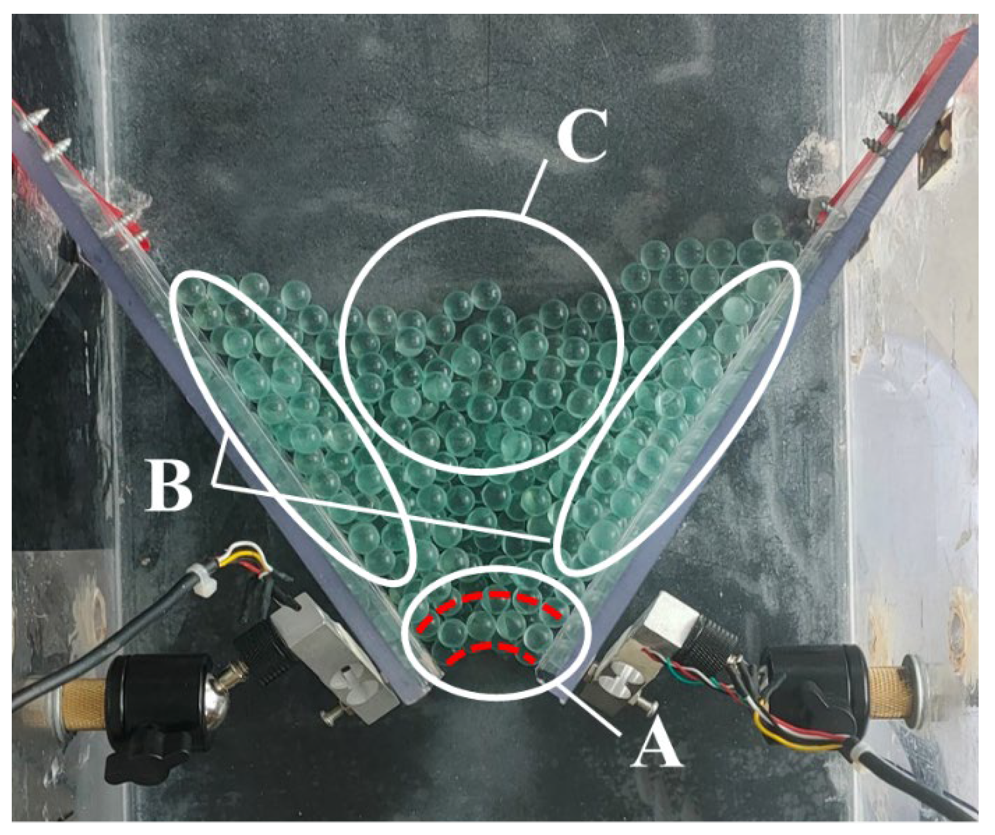
Firstly, according to the experimental results, the particles are directed by the baffle during the dropping. In the transverse baffle structure (θ = 0°), the flowing down direction of particles does not change; a considerable amount of particles may accumulate in the corners on both sides of the baffles, forming a “dead zone”. In the tilted baffle structure, the tilted baffles guide the particles to fall along the inclined baffle direction, eliminating the “possibility of dead zone formation”. This also makes the arching effect and blocking [43,44] over the baffle slit the only way to trap particles. As in Figure 9, when the particles arrive at the baffle structure, the particles in area B move towards the opening under the guidance of the inclined baffle and gradually squeeze and compact due to the impaction of area C, providing good arch foot conditions for arch forming in area A. In addition, the particles in area C constantly impact area A, which may damage the formed stress arch structure. This means that the particle impact in area C not only is conducive to the formation of the arch foot but also hinders the stability of the arch span. Therefore, it can be deduced that there should be a ratio b/d (width diameter ratio) range between the baffle opening width b and the particle diameter d so that the impact of the particles is generally conducive to the formation of the stress arch effect, i.e., make full use of the stress arch effect to capture and intercept the particle flow. It can be found from Figure 6 and Figure 7 that when the b/d ≤ 2, the time difference between the peak value of particle impact force and the stable value is about 0.2~0.4 s, with the decay rate of the impact force generally greater than 4 N/s, and the trapping efficiency E of the baffle to particles remains above 80%. This indicates that the front particles quickly form a stable arch structure after reaching area A, which cannot be damaged even under the impact of subsequent particles, thus preventing particles from flowing out of the baffle opening. When 2 ≤ b/d ≤ 4, the time between the peak value of particle impact force and the stable value is maintained for more than a few seconds, with the decay rate of the impact force generally less than 1 N/s. At this time, the trapping efficiency E of the baffle to particles drops to 5%, which indicates that the strength of the arch structure formed by the particles in area A is reduced, which is continuously destroyed and reformed under the impact of subsequent particles. When the pressure of the residual particles in the baffle is no longer enough to destroy the arch structure, the particles stop flowing. When 4 ≤ b/d, the trapping efficiency E of the baffle to particles drops to zero, indicating that under this opening condition, particles cannot form an arch structure in area A, and eventually, particles completely flow out of the inclined baffle structure; the inclined baffle fails to intercept particles. That said, the width diameter ratio range of the inclined baffle structure to intercept the particle flow is 0 ≤ b/d ≤ 4.

4.3. Trapping Impact Force under Different Relative Opening Widths (Experimental Analysis)

According to the experimental results, it can be found that apart from the trapping efficiency of retaining dams, the impact effect of particles on the safety of retaining dams is also an important consideration when evaluating the performance of normal retaining dams. It can be predicted from the law of conservation of energy that the impact of particles on a completely sealed dam is stronger than that on an open dam under the same conditions. (The release of some particles at the opening reduces the impact.) Therefore, there is likely to be a most appropriate ratio within the effective interception range of the inclined baffle structure 0 ≤ b/d ≤ 4, which can ensure a relatively high trapping efficiency and a weak impact effect, i.e., the ideal interception state. Therefore, this paper proposes an index that can measure both the interception efficiency and dam safety at the same time, with the trapping impact force Ftrap. The specific expression can be given as in Equation (2):
F trap   =   F max E   =   F max   ·   m total m trap
Herein, Fmax is the maximum impact force measured by the sensor during the impact process; E is the trapping efficiency calculated by Equation (1). The trapping impact force Ftrap is a combined factor to evaluate both the impact force and the interception efficiency, which can reflect the change in the interception state. The calculation results of the trapping impact force of each group of experiments are given in Figure 10.
It can be seen from Figure 10 that with the width diameter ratio increasing from 0, the trapping impact force Ftrap of the three sized particles experience a process of first decreasing and then increasing; that is, the change in peak impact force Fmax is not linearly related to particle trapping efficiency E. There is an extreme value of b/d, which makes the inclined baffle rest in the ideal interception state. In Figure 10, the minimum value of the trapping impact force curve of 6 mm particles appears at about b/d = 1.0, while the minimum value of the trapping impact force curve of 10 mm and 14 mm particles appears at about 1 < b/d < 2. When b/d > 2, the decline rate of the trapping efficiency of the baffle to particles is much faster than the decline rate of the maximum impact force until the trapping efficiency is reduced to zero. This shows that when the particle size is in the range of 6~14 mm, the optimal width diameter ratio of the inclined baffle in the ideal interception state is 1 ≤ b/d ≤ 2.

5. Conclusions

Based on the existing research on slit dams, in this paper, a downstream tilted baffle structure was proposed to innovate the traditional slit dam (with transversely set slabs). To verify its advantage over the transverse slab slit dam and explore its applicable conditions, firstly, the discrete element method was used to simulate the impact process of spherical particles on the baffle structure with different inclined angles. Successively, a series of spherical particle flume experiments with tilted baffles were designed and carried out to study the variation laws of particle interception efficiency and the impact force on the baffles under different slit widths and particle sizes. The main conclusions of this paper are as follows:
  • The DEM simulation results indicate that the change of the inclination angle θ of the tilted baffles affects the number of particle collisions, thereby affecting the ability of the baffle structure to dissipate the kinetic energy of particles; when the inclination angle is 30° ≤ θ ≤ 45°, the baffle structure bears less impact force and has better particle kinetic energy dissipation performance.
  • The flume experiment results indicate that the particle size d and the baffle opening width b have an influence on the impact force and trapping efficiency of the inclined baffle structure; with the increase of the width diameter ratio b/d, the peak impact force of the inclined baffle structure decreases nearly linearly, while the trapping efficiency decreases nonlinearly; and the tilted baffles can successfully intercept the flowing down particles when the width diameter ratio range is 0 ≤ b/d ≤ 4.
  • In this paper, the ratio of the maximum impact force to the trapping efficiency (trapping impact force) is proposed to evaluate the interception effect of the tilted baffles. By analyzing this index, it has been found that when the particle size is in the range of 6~14 mm, a suitable width diameter ratio lies in 1 ≤ b/d ≤ 2, which can ensure an ideal interception state for the tilted baffles with relatively weaker impact force and higher trapping efficiency.
As a pilot experiment, this paper considered the impact and accumulation effects of standard spherical particles with the same particle size during the flowing down process. Although the experiment materials deviate from the actual debris flow, it can provide inspiration and reference for preventing and blocking the actual debris flow. As a next step, the application performance of the tilted slit dam in practical engineering will be studied using materials from the real debris flow.

Author Contributions

Conceptualization, Y.F.; methodology, H.L. and X.L.; software, H.L.; validation, H.L.; formal analysis, H.L. and X.L.; investigation, H.L.; resources, Y.F.; data curation, H.L. and L.G.; writing—original draft preparation, H.L.; writing—review and editing, L.G.; visualization, H.L.; supervision, L.G.; funding acquisition, Y.F. All authors have read and agreed to the published version of the manuscript.

Funding

This research was funded by the National Key Scientific Instruments and Equipment Development Projects of China, grant number 41827807.

Institutional Review Board Statement

Not applicable.

Informed Consent Statement

Not applicable.

Data Availability Statement

Data are contained within the article.

Acknowledgments

The authors also extend special thanks to the anonymous reviewers for their valuable comments and recommendations for publishing this paper.

Conflicts of Interest

The authors declare no conflict of interest.

References

  1. Hungr, O.; Leroueil, S.; Picarelli, L. The Varnes classification of landslide types, an update. Landslides 2014, 11, 167–194. [Google Scholar] [CrossRef]
  2. Chen, X.; Cui, P.; You, Y.; Chen, J.; Li, D. Engineering measures for debris flow hazard mitigation in the Wenchuan earthquake area. Eng. Geol. 2015, 194, 73–85. [Google Scholar] [CrossRef]
  3. Pudasaini, S.P.; Hutter, K.; Hsiau, S.S.; Tai, S.C.; Wang, Y.; Katzenbach, R. Rapid flow of dry granular materials down inclined chutes impinging on rigid walls. Phys. Fluids 2007, 19, 053302. [Google Scholar] [CrossRef]
  4. Chen, H.X.; Li, J.; Feng, S.J.; Gao, H.Y.; Zhang, D.M. Simulation of interactions between debris flow and check dams on three-dimensional terrain. Eng. Geol. 2019, 251, 48–62. [Google Scholar] [CrossRef]
  5. Dai, Z.L.; Huang, Y.; Cheng, H.L.; Xu, Q. SPH model for fluid–structure interaction and its application to debris flow impact estimation. Landslides 2017, 14, 917–928. [Google Scholar] [CrossRef]
  6. Shen, W.; Zhao, T.; Zhao, J.; Dai, F.; Zhou, G.G.D. Quantifying the impact of dry debris flow against a rigid barrier by DEM analyses. Eng. Geol. 2018, 241, 86–96. [Google Scholar] [CrossRef]
  7. Canelli, L.; Ferrero, A.M.; Migliazza, M.; Segalini, A. Debris flow risk mitigation by the means of rigid and flexible barriers—Experimental tests and impact analysis. Nat. Hazards Earth Syst. Sci. 2012, 12, 1693–1699. [Google Scholar] [CrossRef]
  8. Leonardi, A.; Goodwin, G.R.; Pirulli, M. The force exerted by granular flows on slit dams. Acta Geotech. 2019, 14, 1949–1963. [Google Scholar] [CrossRef]
  9. Tan, D.Y.; Feng, W.Q.; Yin, J.H.; Zhu, Z.H.; Qin, J.Q. Numerical study of retention efficiency of a flexible barrier in mitigating granular flow comparing with large-scale physical modeling test data. Acta Geotech. 2021, 16, 433–448. [Google Scholar] [CrossRef]
  10. Castanon-Jano, L.; Blanco-Fernandez, E.; Castro-Fresno, D.; Ballester-Munoz, F. Energy dissipating devices in falling rock protection barriers. Rock Mech. Rock Eng. 2017, 50, 603–619. [Google Scholar] [CrossRef] [Green Version]
  11. Volkwein, A.; Schellenberg, K.; Labiouse, V.; Agliardi, F.; Berger, F.; Bourrier, F.; Dorren LK, A.; Gerber, W.; Jaboyedoff, M. Rockfall characterisation and structural protection—A review. Nat. Hazards Earth Syst. Sci. 2011, 11, 2617–2651. [Google Scholar] [CrossRef]
  12. Suwa, H.; Okano, K.; Kanno, T. Behavior of debris flows monitored on test slopes of Kamikamihorizawa Creek, Mount Yakedake, Japan. Int. J. Eros. Control. Eng. 2009, 2, 33–45. [Google Scholar] [CrossRef]
  13. Brighenti, R.; Segalini, A.; Ferrero, A.M. Debris flow hazard mitigation: A simplified analytical model for the design of flexible barriers. Comput. Geotech. 2013, 54, 1–15. [Google Scholar] [CrossRef]
  14. Wang, D.P.; Li, Q.Z.; Bi, Y.Z.; He, S.M. Effects of new baffles system under the impact of rock avalanches. Eng. Geol. 2020, 264, 105261. [Google Scholar] [CrossRef]
  15. Bi, Y.Z.; Du, Y.J.; He, S.M.; Sun, X.P.; Wang, D.P.; Li, X.P.; Liang, H.; Wu, Y. Numerical analysis of effect of baffle configuration on impact force exerted from rock avalanches. Landslides 2018, 15, 1029–1043. [Google Scholar] [CrossRef]
  16. Lei, M.; Yang, P.; Wang, Y.K. Numerical analyses of the influence of baffles on the dynamics of debris flow in a gully. Arab. J. Geosci. 2020, 13, 1052. [Google Scholar] [CrossRef]
  17. Ng, C.W.; Liu, H.; Choi, C.E.; Kwan, J.S.; Pun, W.K. Impact dynamics of boulder-enriched debris flow on a rigid barrier. J. Geotech. Geoenviron. Eng. 2021, 147, 04021004. [Google Scholar] [CrossRef]
  18. Ng CW, W.; Choi, C.E.; Liu LH, D.; Wang, Y.; Song, D.; Yang, N. Influence of particle size on the mechanism of dry granular run-up on a rigid barrier. Géotech. Lett. 2017, 7, 79–89. [Google Scholar]
  19. Zhang, B.; Huang, Y.; Lu, P.; Li, C. Numerical Investigation of Multiple-Impact Behavior of Granular Flow on a Rigid Barrier. Water 2020, 12, 3228. [Google Scholar] [CrossRef]
  20. Redaelli, I.; di Prisco CCalvetti, F. Dry granular masses impacting on rigid obstacles: Numerical analysis and theoretical modelling. Acta Geotech. 2021, 16, 3923–3946. [Google Scholar] [CrossRef]
  21. Ahmadipur, A.; Qiu, T. Impact force to a rigid obstruction from a granular mass sliding down a smooth incline. Acta Geotech. 2018, 13, 1433–1450. [Google Scholar] [CrossRef]
  22. Bernard, M.; Boreggio, M.; Degetto, M.; Gregoretti, C. Model-based approach for design and performance evaluation of works controlling stony debris flow with an application to a case study at Rovina di Cancia (Venetian Dolomites, Northeast Italy). Sci. Total Environ. 2019, 688, 1373–1388. [Google Scholar] [CrossRef] [PubMed]
  23. Rossi, G.; Armanini, A. Impact force of a surge of water and sediments mixtures against slit check dams. Sci. Total Environ. 2019, 683, 351–359. [Google Scholar] [CrossRef] [PubMed]
  24. Sanvitale, N.; Bowman, E.; Cabrera, M.A. Experimental investigation on the impact dynamics of saturated granular flows on rigid barriers. Environ. Eng. Geosci. 2021, 27, 127–138. [Google Scholar] [CrossRef]
  25. Song, E.; Sangjum, I. Influence of debris flow impact on structural stability of check dams. Front. Earth Sci. 2022, 10, 887102. [Google Scholar] [CrossRef]
  26. Piton, G.; Godwin, S.R.; Mark, E.; Strout, A. Debris flows, boulders and constrictions: A simple framework modeling jamming and its consequences on outflow. J. Geophys. Res. Earth Surf. 2022, 127, e2021JF006447. [Google Scholar] [CrossRef]
  27. Jiang, Y.J.; Towhata, I. Experimental Study of Dry Granular Flow and Impact Behavior against a Rigid Retaining Wall. Rock Mech. Rock Eng. 2013, 46, 713–729. [Google Scholar] [CrossRef]
  28. Jiang, Y.J.; Zhao, Y.; Towhata, I.; Liu, D.X. Influence of particle characteristics on impact event of dry granular flow. Powder Technol. 2015, 270, 53–67. [Google Scholar] [CrossRef]
  29. Jiang, Y.J.; Zhao, Y. Experimental investigation of dry granular flow impact via both normal and tangential force measurements. Géotech. Lett. 2015, 5, 33–38. [Google Scholar] [CrossRef]
  30. Jiang, Y.J.; Fan, X.Y.; Li, T.H.; Xiao, S.Y. Influence of particle-size segregation on the impact of dry granular flow. Powder Technol. 2018, 340, 39–51. [Google Scholar] [CrossRef]
  31. Jiang, Y.J.; Fan, X.Y.; Su, L.J.; Xiao, S.-Y.; Sui, J.; Zhang, R.-X.; Song, Y.; Shen, Z.-W. Experimental validation of a new semi-empirical impact force model of the dry granular flow impact against a rigid barrier. Landslides 2021, 18, 1387–1402. [Google Scholar] [CrossRef]
  32. Sun, H.; You, Y.; Liu, J.; Zhang, G.; Feng, T.; Wang, D. Experimental study on discharge process regulation to debris flow with open-type check dams. Landslides 2021, 18, 967–978. [Google Scholar] [CrossRef]
  33. Choi, C.E.; Goodwin, G.R.; Ng CW, W.; Cheung DK, H.; Kwan, J.S.; Pun, W.K. Coarse granular flow interaction with slit structures. Géotech. Lett. 2016, 6, 267–274. [Google Scholar] [CrossRef]
  34. Goodwin, G.R.; Choi, C.E. Slit structures: Fundamental mechanisms of mechanical trapping of granular flows. Comput. Geotech. 2020, 119, 103376. [Google Scholar] [CrossRef]
  35. Marchelli, M.; Leonardi, A.; Pirulli, M.; Scavia, C. On the efficiency of slit-check dams in retaining granular flows. Géotechnique 2020, 70, 226–237. [Google Scholar] [CrossRef]
  36. Zhang, B.; Huang, Y.; Liu, J. Micro-mechanism and efficiency of baffle structure in deceleration of granular flows. Acta Geotech. 2021, 16, 3667–3688. [Google Scholar] [CrossRef]
  37. Huang, Y.; Zhang, B.; Zhu, C. Computational assessment of baffle performance against rapid granular flows. Landslides 2021, 18, 485–501. [Google Scholar] [CrossRef]
  38. Sun, H.; You, Y.; Liu, J.F. Experimental study on characteristics of trapping and regulating sediment with an open-type check dam in debris flow hazard mitigation. J. Mt. Sci. 2018, 15, 2001–2012. [Google Scholar] [CrossRef]
  39. Ishikawa, N.; Shima, J.; Matsubara, T.; Tatesawa, H.; Horiguchi, T.; Mizuyama, T. Trapping mechanism of debris flow by steel open dams. In Proceedings of the INTERPRAEVENT, 2014 International Symposium, Nara, Japan, 25–28 November 2014. [Google Scholar]
  40. Law, R.P.H.; Choi, C.E.; Ng, C.W.W. Discrete-element investigation of influence of granular debris flow baffles on rigid barrier impact. Can. Geotech. J. 2016, 53, 179–185. [Google Scholar] [CrossRef]
  41. Gong, S.; Zhao, T.; Zhao, J.; Dai, F.; Zhou, G.G.D. Discrete element analysis of dry granular flow impact on slit dams. Landslides 2021, 18, 1143–1152. [Google Scholar] [CrossRef]
  42. Cui, Y.; Choi, C.E.; Liu, L.H.D.; Ng, C.W.W. Effects of particle size of mono-disperse granular flows impacting a rigid barrier. Nat. Hazards 2018, 91, 1179–1201. [Google Scholar] [CrossRef]
  43. Fang, Y.; Guo, L.; Hou, M. Arching effect analysis of granular media based on force chain visualization. Powder Technol. 2020, 363, 621–628. [Google Scholar] [CrossRef]
  44. Fang, Y.; Li, X.; Guo, L.; Gu, R.; Luo, W. The experiment and analysis of the repose angle and the stress arch-caused stress dip of the sandpile. Granul. Matter 2022, 24, 7. [Google Scholar] [CrossRef]
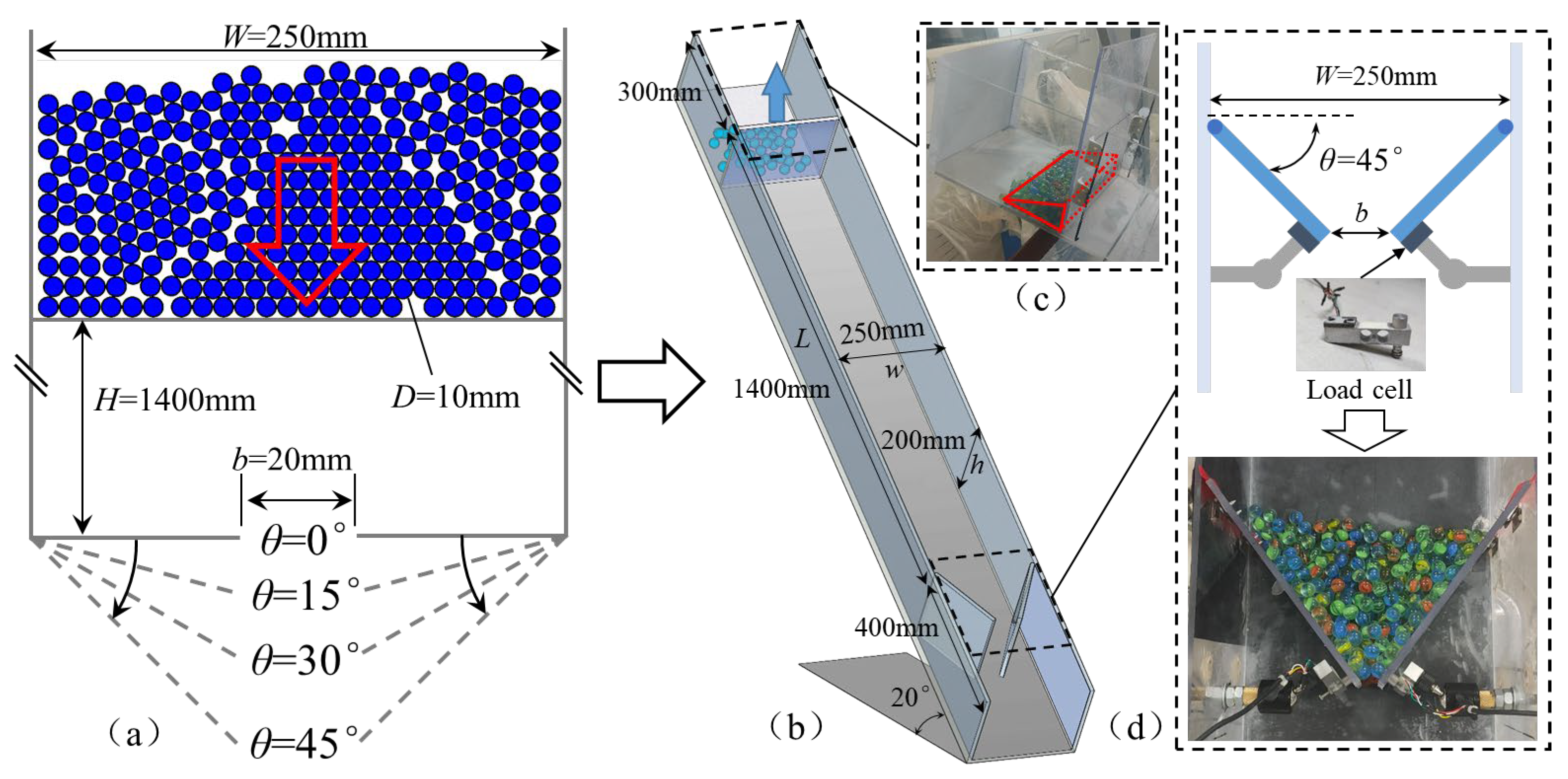
Figure 1. (a) schematic diagram of DEM method simulating flume model; (b) schematic diagram of flume experimental device; (c) particle hopper; (d) baffle impact force measuring sensor.
Water 14 02772 g001
Figure 2. Schematic diagram of granular material: (a) d = 6 mm; (b) d = 10 mm; (c) d = 14 mm.
Water 14 02772 g002
Figure 3. Schematic diagram of the velocity variation of the particle impacting the baffle structure with different inclination angles obtained from the DEM simulation. t is the time that the particles begin to move and fall.
Water 14 02772 g003
Figure 4. DEM simulation statistical results of the particle system under different baffle angle conditions. (a) changes in particle contact number; (b) changes in kinetic energy of the system.
Water 14 02772 g004
Figure 5. Maximum impact force under different baffle angle conditions, normalized with the maximum impact force of the baffle with θ = 0°.
Water 14 02772 g005
Figure 6. Variation of particle impact force with time in the flume experiment when θ = 45°. (a) b = 0 mm; (b) b = 10 mm; (c) b = 15 mm; (d) b = 20 mm; (e) b = 25 mm; (f) b = 30 mm; (g) b = 35 mm; (h) b = 40 mm; (i) summary of maximum impact forces for different slit widths. All impact force time history curves were recorded from the moment the particles first contacted the baffle structure.
Water 14 02772 g006
Figure 7. Particle trapping efficiency of inclined baffle structure with θ = 45° under different slit widths.
Water 14 02772 g007
Figure 8. Schematic diagram of particle rebound form in baffle structure with different inclination angles (a) θ = 0°; (b) θ = 45°. The red arrow represents the part of particles that do not collide with the baffle structure, and the black arrow represents the part of particles that collide and bounce with the baffle structure.
Water 14 02772 g008
Figure 9. Schematic diagram of particles jamming in the inclined baffle structure, in which the white circle is the divided particles that have different effects on jamming, and the red dotted line is the arch structure formed by the particles at the opening. (A) is the arch forming area; (B) is the extrusion area; (C) is the impact area.
Water 14 02772 g009
Figure 10. Trapping impact force of particles on inclined baffle structure under different relative opening widths.
Water 14 02772 g010
Table 1. DEM input parameters.
ParametersValues
Wall normal stiffness (N/m)1 × 108 [42]
Wall normal-to-shear stiffness ratio (dimensionless)1 [42]
Particle normal stiffness (N/m)1 × 108 [42]
Particle normal-to-shear stiffness ratio (dimensionless)1 [42]
Ball radius (mm)5
Ball density (kg/m3)2550
Inter-ball friction coefficient (dimensionless)0.36 [42]
Interface-ball friction coefficient (dimensionless)0.4 [42]
Gravitational acceleration (m/s2)9.81 [42]
Coefficient of restitution (dimensionless)0.78 [42]
Table 2. Properties of granular materials.
ParametersValues
Diameter(mm)61014
Density (kg/m3)255025502550
Initial bulk density (kg/m3)154914871380
Young’s modulus (GPa)606060
Poisson ratio0.250.250.25
Dynamic friction angle (°)17.216.614.7
Static friction angle (°)283034
Table 3. Flume experiment conditions.
Experiment IDSlit Size, b (mm)Particle Diameter, d (mm)Slit Size to Particle Size Ratio, b/d
B0-D6060.00
B0-D100100.00
B0-D140140.00
B10-D61061.67
B10-D1010101.00
B10-D1410140.71
B15-D61562.50
B15-D1015101.50
B15-D1415141.07
B20-D62063.33
B20-D1020102.00
B20-D1420141.43
B25-D62564.17
B25-D1025102.50
B25-D1425141.79
B30-D63065.00
B30-D1030103.00
B30-D1430142.14
B35-D63565.83
B35-D1035103.50
B35-D1435142.50
B40-D64066.67
B40-D1040104.00
B40-D1440142.86
Publisher’s Note: MDPI stays neutral with regard to jurisdictional claims in published maps and institutional affiliations.