Article

Concerning Dynamic Effects in Pipe Systems with Two-Phase Flows: Pressure Surges, Cavitation, and Ventilation

1
Department of Civil Engineering, Architecture and Georesources, CERIS, Instituto Superior Técnico, University of Lisbon, 1049-001 Lisbon, Portugal
2
Department of Hydraulic and Environmental Engineering, Universitat Politècnica de València, 46022 Valencia, Spain
3
School of Civil Engineering, Architecture and Urban Design, State University of Campinas, Campinas 13083-889, Brazil
4
Facultad de Ingeniería, Universidad Tecnológica de Bolívar, Cartagena 131001, Colombia
5
School of Civil Engineering, University of Leeds, Leeds LS2 9JT, UK
6
College of Water Conservancy and Hydropower Engineering, Hohai University, 1 Xikang Rd., Nanjing 210098, China
7
Department of Civil and Mineral Engineering, University of Toronto, Toronto, ON M5S 1A4, Canada
*
Author to whom correspondence should be addressed.
Water 2022, 14(15), 2376; https://doi.org/10.3390/w14152376
Submission received: 7 July 2022 / Revised: 26 July 2022 / Accepted: 28 July 2022 / Published: 31 July 2022
(This article belongs to the Special Issue Hydraulic Transients in Water Distribution Systems)

Abstract

:
The risks associated with unsteady two-phase flows in pressurized pipe systems must be considered both in system design and operation. To this end, this paper summarizes experimental tests and numerical analyses that highlight key aspects of unsteady two-phase flows in water pipelines. The essential dynamics of air–water interactions in unvented lines are first considered, followed by a summary of how system dynamics change when air venting is provided. System behaviour during unsteady two-phase flows is shown to be counter-intuitive, surprising, and complex. The role of air valves as protection devices is considered as is the reasonableness of the usual assumptions regarding air valve behaviour. The paper then numerically clarifies the relevance of cavitation and air valve performance to both the predicted air exchanges through any installed air valves and their role in modifying system behaviour during unsteady flows.
Key Contribution: Air–water mixtures in water pipelines create a range of complex and sometimes pathological system responses, but such challenges can be at least partly overcome through understanding, careful design and operation, and judicious component selection.

1. Introduction

Although air is normally an unwanted guest in pressurized piping systems, many situations are conducive to introducing air, to air pocket formation, and to air entrapment in pipe systems. Common air-inducing events include filling and emptying operations, air intake by air valves, service interruptions, pressure decreases at suction pipes, valves or other pipeline singularities, pipe bursts, intrusion through small cracks in regions with negative pressures [1]. Unmanaged entrapped air in pressurized water pipelines often leads to operational problems: additional head-losses, reduced pump or turbine efficiency, noisy flow, corrosion of metallic pipes, measurement errors, unwanted vibrations, and intensified transient events [2,3]. Importantly, air pockets, even when designed to mitigate transients, have the potential of exacerbating hydraulic transients in pressurized pipelines [4].
Transient flows are a particularly notable concern. Such events are a common occurrence in pumping and gravity water pipelines, hydraulic circuits of hydropower plants, irrigation systems, refrigeration circuits, and lines for the conveyance of fuel or chemical products [5]. Exceedingly high pressures can cause the rupture of pipes or appurtenances, while sub-atmospheric pressures can lead to the collapse of thin-walled pipes, inflow of pollutants in potable water systems, release of previously dissolved air, and formation of vapour cavities [6,7]. Air pockets influence the dynamics of unsteady pipe flows in several circumstances of pipeline operation: filling, draining, water hammer events, and pipe bursts [8,9,10,11]. The transient behaviour of a system containing air is often complex because of air–water interactions and the marked difference between the properties of air and water [12,13]. To explore the relevance of entrapped air during unsteady pipe flows in hydraulic systems, experimental tests have been conducted in a variety of locations, including at the hydraulics laboratory of the Instituto Superior Técnico, University of Lisbon. More specifically, filling and draining tests have been conducted for confined or vented lines and have been conclusively shown to constitute a real threat to safe and reliable operation. Elucidative results from such experimental tests are presented and interpreted in this paper.
An important strategy for air management in pressurized pipelines is to employ air valves as protection devices, components designed to allow for the necessary air exchanges during operations such as filling, draining, and water hammer events [2]. The main types of air valves are air-release valves (ARVs) that expel accumulated air during normal line operation; air/vacuum valves (AVVs) that permit air exchanges during line filling, draining, and water hammer events; combination air valves (CAVs) that perform the roles of ARVs and AVVs; and vacuum breakers (VBs) that admit air in large quantities with very small sub-atmospheric pressures and thus avoid more severe pressures. These VBs are particularly useful as protection devices in large-diameter thin-walled lines [11]. If well-chosen and well-maintained, air valves can considerably improve the overall hydraulic performance of a pressurized pipeline system. Improper air valve selection, incorrect operational procedures, or poor device response because of a lack of periodical maintenance may lead to serious operational issues [11,14]. Thus, special attention must be put into air valve selection and sizing. In general, air should be freely admitted by the air valve in the hypothesis of sub-atmospheric pressure inside the line. However, the air present in pipes must be expelled with care, perhaps with enough “delicacy” to avoid excessively high-pressure spikes upon air valve closure [15].
As essential information in the selection and sizing of air valves comes their characteristic curves. Most manufacturers provide curves that indicate the relation between differential pressure through the device and air flow rate [16]. Such curves, however, might not always be representative of actual air valve behaviour [17]. In the Polytechnic University of Valencia, static air flow tests were performed for many air valve models to determine their characteristic curves. When comparing the experimental results with the data provided by manufacturers, important discrepancies were found [18]. The curves provided by manufacturers, however, are often used by designers to select and size air valves. In the case of using an unrepresentative characteristic curve, the resulting design may result in potentially dangerous sizing errors. Unfortunately, given the multitude of design conceptions and sizes of air valves available on the market, only anecdotal generalizations regarding air valve behaviour are available [10]. Furthermore, undertaking well-controlled characterization tests is often unfeasible in practical situations [19,20].
The current paper describes and explores key aspects of air–water interactions in pressurized hydraulic circuits, namely the filling of confined lines, filling of ventilated lines, pipeline draining with air valve protection, pipeline draining without air valve protection (in this case, with the possibility of backflow air intrusion), air valve behaviour as a function of differential pressure across the device and common issues related to air valve characterization, challenges associated with the application of air valves (with a discussion of commonly used practice recommendations), macro-cavitation due to down-surge events, and air exchanges through air valves during unsteady flows.

2. Two-Phase Flows in Pressurized Systems

Air in pressurized systems can be dissolved or present as either bubbles or pockets. At summits within pipeline profiles, if the water discharge is insufficient to carry entrapped air downstream and the air is not vented, buoyancy causes air to accumulate, potentially forming large air pockets [1,21]. The water phase generally dominates in pressurized water pipelines, i.e., the superficial velocity of water far exceeds the superficial velocity of air, even if air pockets are entrapped in the system [22]. The drag force that acts on a given air pocket is downstream, while the buoyant force pushes the air pocket upstream in downward pipe segments and downstream in upward-sloping segments [23]. Because of this, air pockets have a general tendency to accumulate at high points and to break apart at low elevation bends and elbows [24]. Thus, it is natural to install air valves near the upstream ends of steep downward pipe segments to avoid air accumulation [25]. Several researchers have studied the necessary conditions for air removal by hydraulic means in downward pipe segments, but critical velocity relations are still elusive [21,22,23,26].
The admission of air into a hydraulic system is not always necessarily problematic and may actually act as a mechanism for system protection against severe water hammer events, particularly down-surges [27]. On the one hand, dissolved air decreases the bulk modulus of the flowing fluid, thus reducing the celerity of the propagation of pressure waves [5]. Entrapped air pockets, by contrast, can exacerbate pressure oscillations during unsteady pipe flows. In the pipeline filling tests conducted by Martins (2013) [4], maximum transient pressures were consistently larger when the experimental apparatus contained some air than when it only contained water. Importantly, entrapped air greatly increases the complexity of transient flows in piping systems [8]. During the pressurization of a line with a large entrapped air pocket, significant movement of the liquid masses is expected, an outcome directly associated with the high compressibility of the air phase. The fluid dynamics in both phases (air pocket and liquid column), in response to an introduced excitation (pressurization differential), are responsible for intense vorticity in the first cycles of the transient oscillations. The formation and movement of vortices constitute a key mechanism of energy dissipation, decisively contributing to the marked damping of the pressure fluctuations of transients with trapped air [12].

2.1. Pipeline Filling Operations

2.1.1. Confined System

Pipeline filling tests were conducted by Martins (2013) [4] at the Instituto Superior Técnico, University of Lisbon, Portugal, to investigate the transient behaviour of systems containing entrapped air. This dedicated section describes and interprets experimental results from these tests that give insight into the relevance of air pocket and system characteristics to system transient behaviour during pipeline filling. Indeed, experimental and numerical studies found in the literature evince the importance of air pocket and system characteristics on the transient behaviour of rapid filling pipelines [8,12,28,29]. The system in Figure 1a comprises an upstream pressurized tank (providing an initial absolute pressure p R 0 * to the system), control valve V1, downstream vertical segment (connected by a horizontal pipe segment to the control valve V1), and downstream air pocket at the vertical segment (with initial air length L a 0 and initial absolute pressure p a 0 * ). The test pipeline is 3.35 m long, with an internal diameter of 53.6 mm, constructed of PVC DN63/PN16 pipes. The line is filled by the opening of valve V1 (opening time of 0.23 s) for a given condition of p R 0 * , L a 0 , and p a 0 * . Parameters of interest include the piezometric head h * (which varies through time) and the maximum piezometric head h max * associated with each test condition. The tested conditions included seven values of p R 0 * (ranging from 1.5 to 4.5 bar), seven values of L a 0 (ranging from zero to 1.0 m), and five values of p a 0 * (ranging from 1.0 to 3.0 bar).
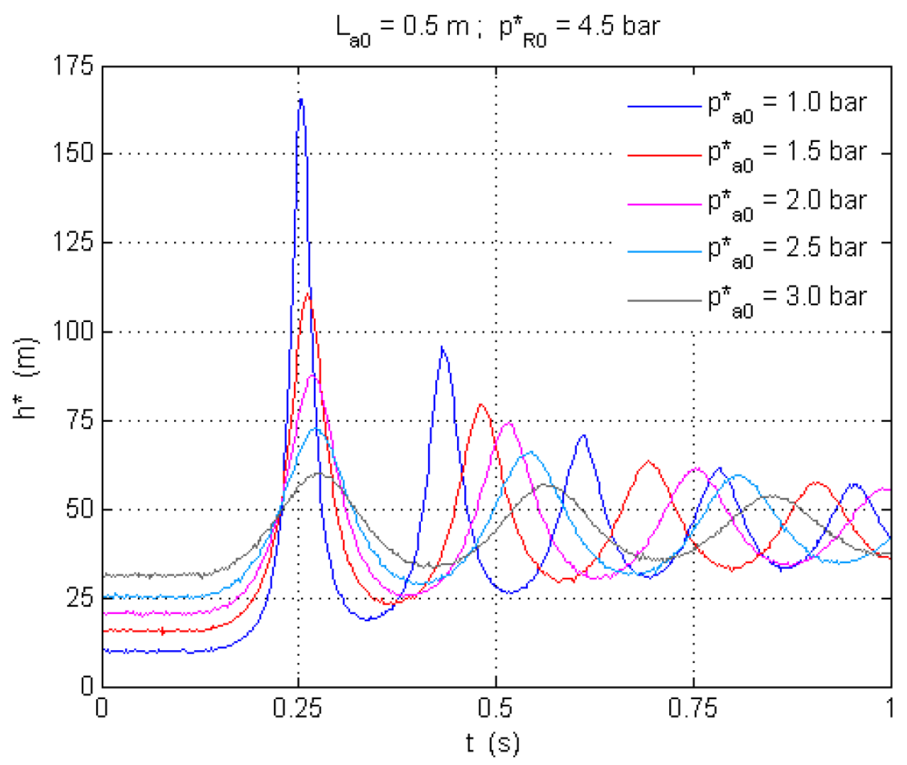
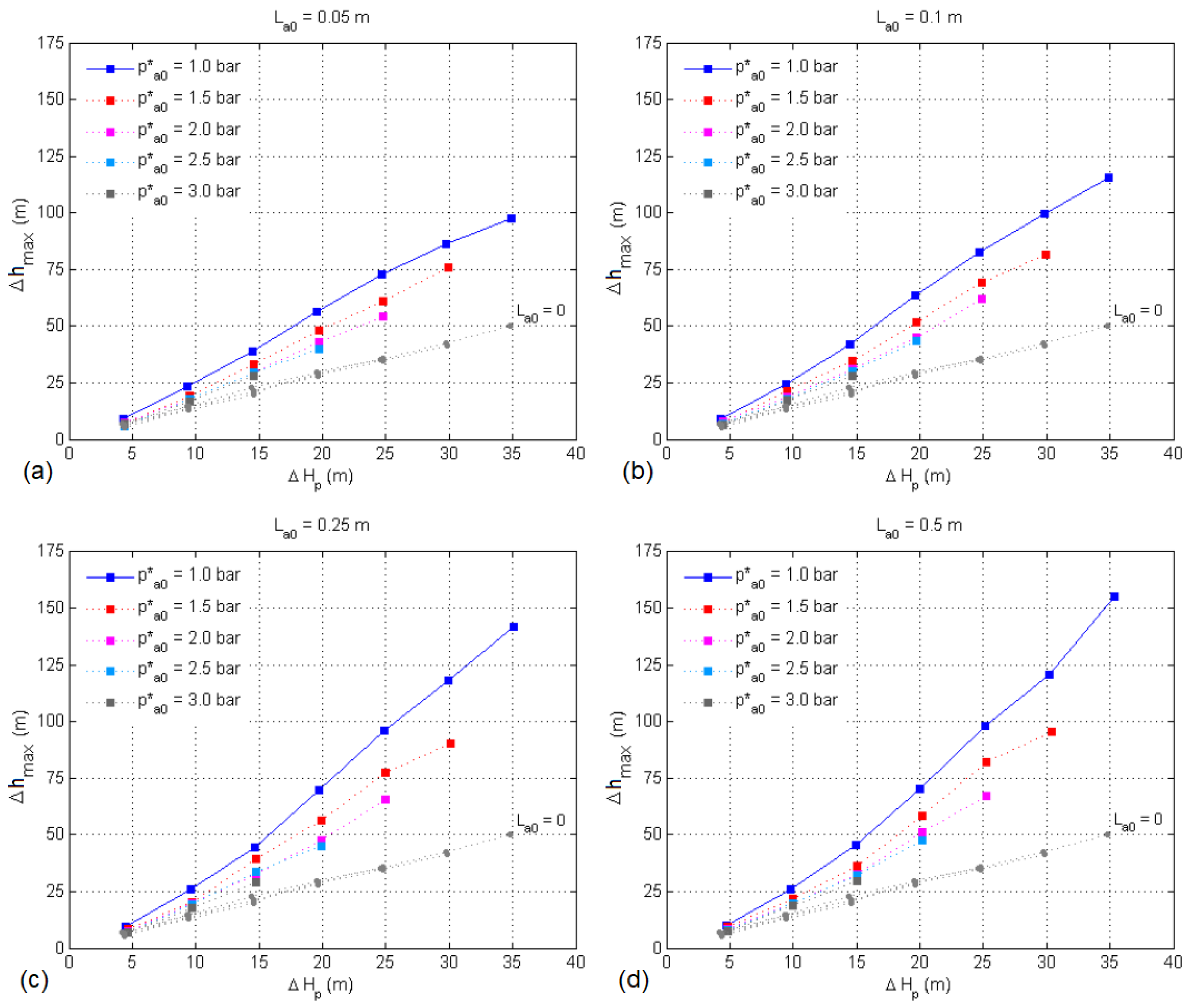
Figure 1b compares the results of tests with p R 0 * = 4.5 bar and p a 0 * = 1.0 bar and several air pocket size conditions, i.e., L a 0 = 0 (without entrapped air) or L a 0 > 0 ( L a 0 = 0.10 m, L a 0 = 0.50 m, and L a 0 = 1.0 m). The same figure shows that the transient pressure oscillations for the case without entrapped air ( L a 0 = 0 ) are milder than the oscillations for the cases with entrapped air. From Figure 1c, it can be inferred that there is an intermediary value of L a 0 for which the amplitude of the first pressure peak, represented by h max * , is the largest, especially for the cases with higher values of inlet pressure. The situations depicted in Figure 1 consider p a 0 * = 1.0 bar. In practice, however, air pocket pressure is often not atmospheric and can considerably affect the amplitude and frequency of transient oscillations. Importantly, in Figure 2, it is observed that even a mild increase in the initial air pocket pressure, from 1.0 to 1.5 bar, for example, is sufficient for a meaningful reduction of h max * . Additionally, increments in initial air pocket pressure increase the period of oscillation of pressure waves. Figure 3 shows the influence of air pocket size and pre-pressurization level on the system’s reaction to pressurization—with such reaction represented by Δ h max = h max * h a 0 * . For all air pocket sizes, if the air pocket is slightly pre-pressurized, the system reaction is significantly attenuated in comparison to the case with atmospheric pressure, particularly in the domain of the most aggressive spikes or the largest Δ H p values. For Δ H p 30 m, the reduction of Δ h max due to a slight increase in initial air pocket pressure reached 12% for L a 0 = 0.05 m and 21% for L a 0 = 0.50 m. The relative attenuation of system response, reflected in the values of Δ h max , was observed to progressively decrease with additional increments of 0.5 bar in the pre-pressurization level.
Figure 4 shows the behaviour of the air–water interface during filling tests using the testing apparatus depicted in Figure 1a. Each image is numbered to represent a specific transient phase: (1) the initial stage before the upstream valve is opened; (2) the intermediary stage during the first air pocket compression; (3) when the air pocket compression reaches its maximum, i.e., the air pocket reaches its minimum size; (4) the intermediary stage during the first air pocket expansion; (5) the air pocket reaches its maximum decompression; (6) the intermediary stage during the second air pocket compression; and (7) the air pocket reaches its second-smallest size. For the case depicted in Figure 4a, upon the start of the expansion process (phase 4 onwards), an intense air–water mixture takes place. Because of this, the air–water interface does not remain mostly perpendicular to the longitudinal direction of the pipe. In Figure 4b, from phase 4 onwards, the air–water interface clearly loses any well-defined structure. The mixing of air and water in Figure 4a looks more intense than that in Figure 4b—the key difference between these two cases is that p R 0 * is larger for the case in Figure 4a. The air–water interfaces in both cases depicted in Figure 4 can be classified as badly behaved. For some conditions, however, the air–water interface can remain relatively stable during the transient phenomenon.
The following conditions resulted in relatively well-behaved air–water interfaces: L a 0 = 0.10 m, p a 0 * = 1.0 bar, p R 0 * = 2.0 bar; L a 0 = 0.10 m, p a 0 * = 1.0 bar, p R 0 * = 3.0 bar; L a 0 = 0.25 m, p a 0 * = 3.0 bar, p R 0 * = 4.0 bar; and L a 0 = 0.50 m, p a 0 * = 3.0 bar, p R 0 * = 4.0 bar. In contrast, the following conditions—in addition to the ones in Figure 4—resulted in badly behaved air–water interfaces: L a 0 = 0.10 m, p a 0 * = 1.0 bar, p R 0 * = 4.0 bar; L a 0 = 0.25 m, p a 0 * = 1.0 bar, p R 0 * = 2.0 bar; and L a 0 = 0.25 m, p a 0 * = 1.0 bar, p R 0 * = 4.0 bar. In general, air–water mixing and air–water interface instability are facilitated for larger air pockets, more intense differential pressures, and smaller initial air pocket pressures.
Figure 4b shows CFD results together with pictures of the filling phenomenon—such a CFD approach considers a VOF formulation. For the filling tests, the CFD modelling was undertaken with the use of ANSYS Fluent. A triangular unstructured mesh was used. The κ ϵ model was considered for turbulence modelling. Despite the substantial complexity of the air–water interface evolution in the case depicted in Figure 4b, there is reasonable agreement between the numerical results and the experimental data. For reference, for L a 0 = 0.10 m, p a 0 * = 1.0 bar, and p R 0 * = 4.0 bar, the error between the measured and simulated maximum transient pressure values is less than 1%. In contrast, for L a 0 = 0.50 m, p a 0 * = 1.0 bar, and p R 0 * = 4.0 bar, such error is of about 19%. The results presented in Figure 4 show that, even for vertical pipe segments and depending on the conditions prior to line filling, the disruption of the air–water interface and intense air–water mixture may take place.

2.1.2. Ventilated System

This section describes and interprets experimental results obtained by Martins (2013) [4] that give insight into the relevance of the air pocket size, system characteristics, and orifice size to system behaviour during pipeline filling. Indeed, experimental and numerical studies found in the literature reveal the importance of orifice size on the transient behaviour of rapid filling pipelines [15,30,31,32,33,34,35,36]. The vented filling tests used the test pipeline depicted in Figure 1a but with a downstream orifice or air valve and p a 0 * always equal to 1.0 bar. The following orifice sizes were tested: 1.0, 1.95, 2.95, 3.90, and 4.88 mm (and also a 2.55 mm orifice air valve). The tested conditions included five values of p R 0 * (ranging from 2.0 to 4.0 bar) and seven values of L a 0 (ranging from 0 to 1.0 m).
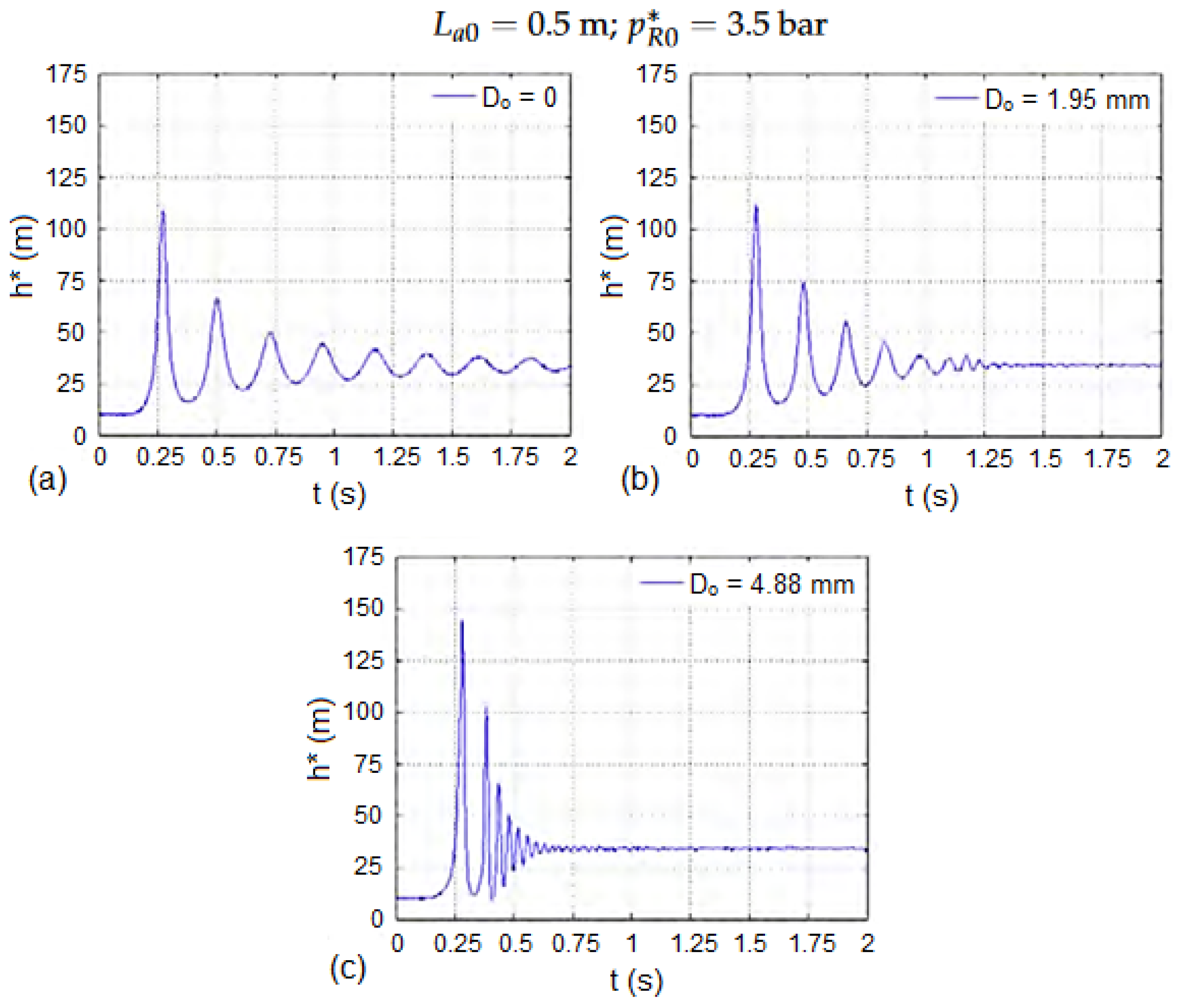
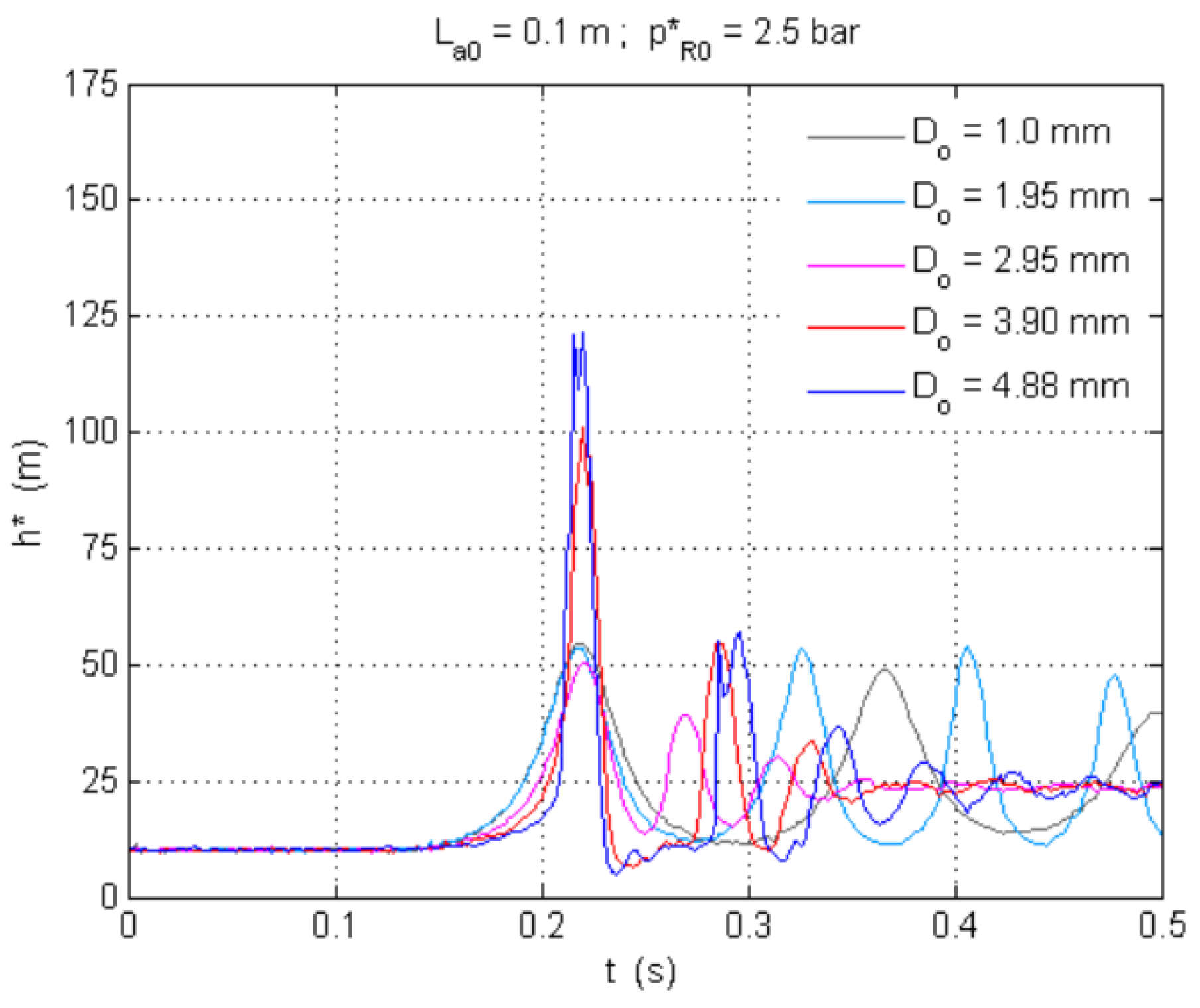
Figure 5 shows the orifice size-dependent response to pressurization for the test pipeline with L a 0 = 0.50 m and p R 0 * = 3.5 bar. If entrapped air is absent, like in the right portions of the pressure oscillations in the graphs in Figure 5b,c, the oscillations have a high frequency (characteristic of airless transients). There is a reciprocal relation between the duration of the transient phenomenon and orifice size. In the test with D o = 1.95 mm (Figure 5b), the cushioning effect prevailed during a relevant period of the pressurization process because of the relatively reduced orifice flow capacity. Later, after the complete removal of the air, the pressure oscillation had a lower amplitude with the characteristic frequency of airless transients. As the size of the downstream orifice increases, so does the amplitude of pressure oscillations—as clearly observed between the case with D o = 0 in Figure 5a (lower amplitude) and the case with a relatively large orifice in Figure 5c (higher amplitude). The duration of the pressure oscillations influenced by the air cushion effect decreases with orifice size. Figure 6 also explores the influence of D o on the system transient response to pressurization—in this case, however, all orifice sizes are considered, L a 0 = 0.10 m, and p R 0 * = 2.5 bar. Such influence depends on L a 0 and is decisive for small L a 0 values. For L a 0 0.25 m, extreme transient pressures were greatly amplified for the largest orifices ( D o = 3.90 mm and D o = 4.88 mm). This amplification, associated with the impact of the water front with the orifice, loses relevance for larger sizes of initial entrapped air.
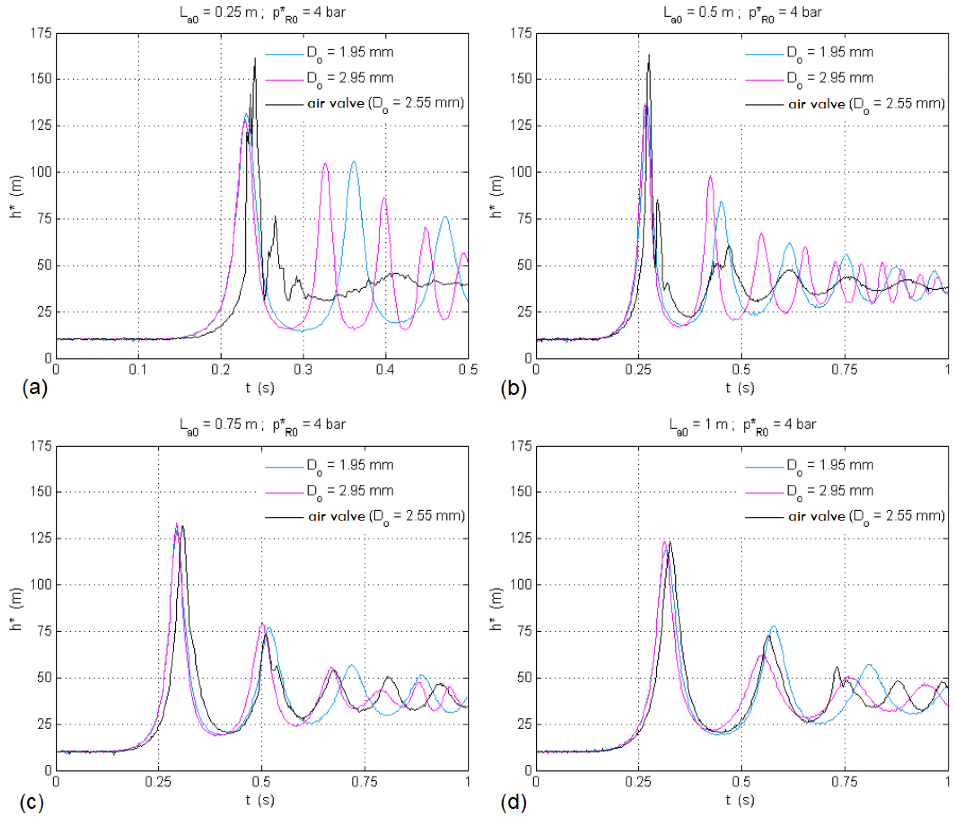
Figure 7 shows the influence of air pocket length and orifice size (1.95 or 2.95 mm orifice or 2.55 mm air valve) on the system response to pressurization. For relatively small air pockets, L a 0 equals to 0.25 or 0.50 m (Figure 7a,b), the maximum pressure for the case with the 2.55 mm air valve is larger than for the cases with 1.95 and 2.95 mm orifices. A key distinction between the cases with orifices and the case with an air valve is that for the latter, expulsion stops when the water reaches the air valve’s float, while for the former, water is expelled through the orifice as it is choked by water. In addition, the air flow through an air valve is more complicated from a fluid dynamics point of view than the air flow through an orifice—the interior of an air valve generally includes tortuous surfaces. In Figure 7, for the cases in which L a 0 is equal to 0.25 or 0.50 m, the pressure oscillations for the case with an air valve are less smooth than for the cases with orifices. In general, large L a 0 values have a positive effect on transient events—as L a 0 increases, h max * tends to decrease. Additionally, as L a 0 increases, so does the oscillation period of pressure waves. For relatively large air pockets, L a 0 equals to 0.75 or 1.0 m (Figure 7c,d), the relevance of orifice size to the magnitude of the maximum transient pressure is much reduced.

2.2. Pipeline Draining Operations

2.2.1. Progression of Hydraulic and Thermodynamic Variables

Emptying processes are characterized by the expansion of entrapped air pockets as water columns exit hydraulic installations. Unsteady pipeline flows from draining operations must be considered in pipeline design and operational planning. Indeed, for thin-walled large-diameter pipelines, sub-atmospheric pressures might lead to pipeline collapse, particularly for unburied lines [37]. Thus, any emptying operation must be done slowly—according to the M51 manual by AWWA, draining velocities should not surpass 0.3 to 0.6 m/s [11]. Emptying processes can be better understood through the polytropic model for air pocket evolution. According to the polytropic model, a positive variation in air pocket volume produces a negative variation in air pocket pressure. This effect typically occurs right after the beginning of the draining transient event, when air valves are still not fully operational. To recover atmospheric conditions at air pockets during draining, air valves should be designed to have sufficient admission capacity to keep up with the progression of water removal. At the end of a draining transient event in a vented system, the air phase reaches atmospheric conditions [9]. In emptying processes, the larger the air valve, the milder the values of down-surges. Air valves are important for the protection of water installations against pipeline collapse. In the current literature, there is no evidence of additional transient flow effects from oversized air valves during emptying procedures.
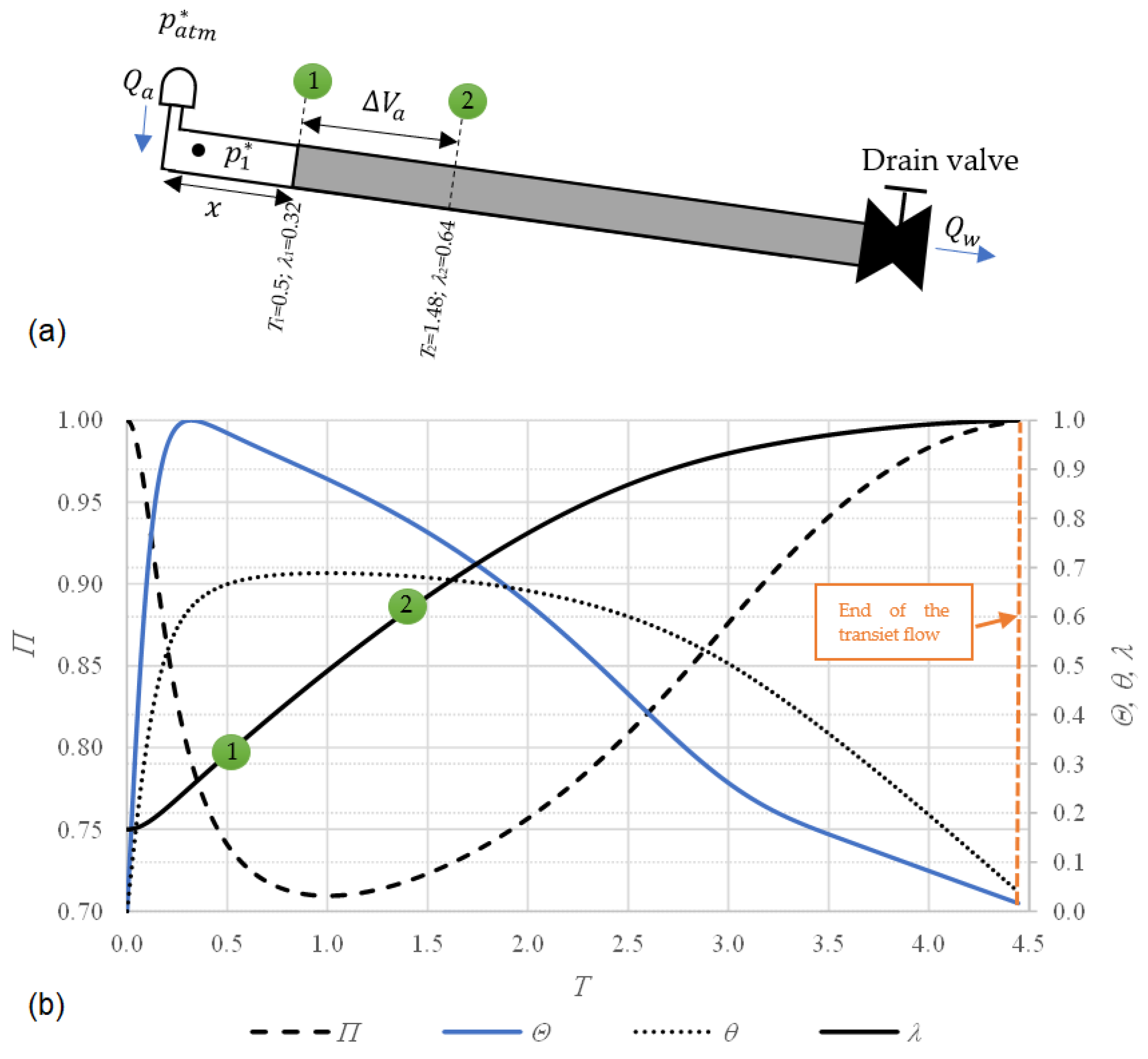
To gauge the order of magnitude of hydraulic and thermodynamic variables during draining (mainly air pocket pressure, water discharge, air flow, and air pocket size), the unsteady pipeline flow during a typical emptying operation of a test pipeline was numerically simulated. A 600 m-long pipeline with an internal diameter (D) of 400 mm was considered. The pipeline had a longitudinal slope of 0.04 rad, an air valve with an outlet internal diameter ( D av ) of 50 mm, an admission coefficient of 0.65, a drain valve with a flow factor ( K v ) of 2150 m 3 /h/bar 0.5 , a constant friction factor (f) of 0.018, a polytropic coefficient (k) of 1.2, an initial air pocket size ( x 0 ) of 100 m, and an initial air pocket pressure ( p 1 , 0 * ) of 101,325 Pa. Figure 8a shows the schematics of the test pipeline. At the beginning of the transient flow, the system is at rest ( v 0 = 0 ). The following dimensionless parameters were used for the interpretation of the transient phenomenon: dimensionless air pocket pressure Π = p 1 * / p atm * (where p 1 * is air pocket pressure, and p atm * is atmospheric pressure), dimensionless water flow Θ = Q w / Q w , max (where Q w is the water flow, and Q w , max is the maximum water flow during the transient event), dimensionless air flow θ = Q a / Q w , max (where Q a is air flow), dimensionless air pocket size λ = x / L T (where x is the length of the air pocket, and L T is the total length of the pipe), and dimensionless time T = t / t p * (where t is time, and t p * is the peak time when the maximum water flow is reached).
Figure 8a shows how the air volume changes from points 1 to 2, where for a value of T 1 = 0.5 , the dimensionless air pocket size is λ 1 = 0.32 , while for T 2 = 1.48 , the air pocket size is twice as large ( λ 2 = 0.64 ). In fact, the air pocket is continuously expanding throughout the draining process. Figure 8b details the evolution of hydraulic and thermodynamic variables during the emptying operation. The air pocket pressure pattern is characterized by a decreasing trend, from Π = 1.0 (at T = 0 ) to Π = 0.71 (at T = 1.02 ), and an increasing trend, from Π = 0.71 to 1.0 (at the end of the transient flow when the atmospheric condition is reached). Regarding the water flow pattern, a maximum value is found at T = 0.31 . After that, the drained water discharge ( Q w ) reduces over time until the end of the phenomenon. To reduce the intensity of the pressure drop, air valves should admit air with a sufficiently fast rate ( Q a ). In this sense, considering dimensionless times from 0 to 1.93, the water flow oscillations provide higher values compared to the air flow pulses. After a dimensionless time of 1.93, this tendency changes, showing that the injected air volume is greater than the drained water volume. For draining operations, engineers and designers should always evaluate the risk of pipeline collapse based on pipe catalogues. The pipe’s stiffness class should be selected considering aspects such as cover depth, native soil, backfill type, and the minimum value of the air pocket pressure oscillation pattern [37].

2.2.2. Backflow Air Intrusion

Air valves often play a crucial role in pipeline draining operations. Some other aspects that are also influential are draining valve manoeuvre, backflow air intrusion, pipe diameter, pipeline profile, and air pocket size and location. This section in particular discusses the importance of backflow air intrusion during pipeline draining. Backflow air intrusion occurs at the downstream end of a hydraulic system, i.e., at the pipeline location where water leaves the line. The magnitude of backflow air intrusion is influenced by factors such as pipeline layout and end throttling condition. The main characteristic that causes the inception of backflow air intrusion during pipeline draining is the development of a sub-atmospheric pressure condition inside the trapped air pocket associated with the water column being drained from the line [38]. The dimension of the trapped air pocket directly affects the magnitude of sub-atmospheric pressures. The standing position of the air pocket also has an influence on the phenomenon. The specific operation of the draining valve is also significant, which must be considered carefully in terms of the valve opening time and degree.
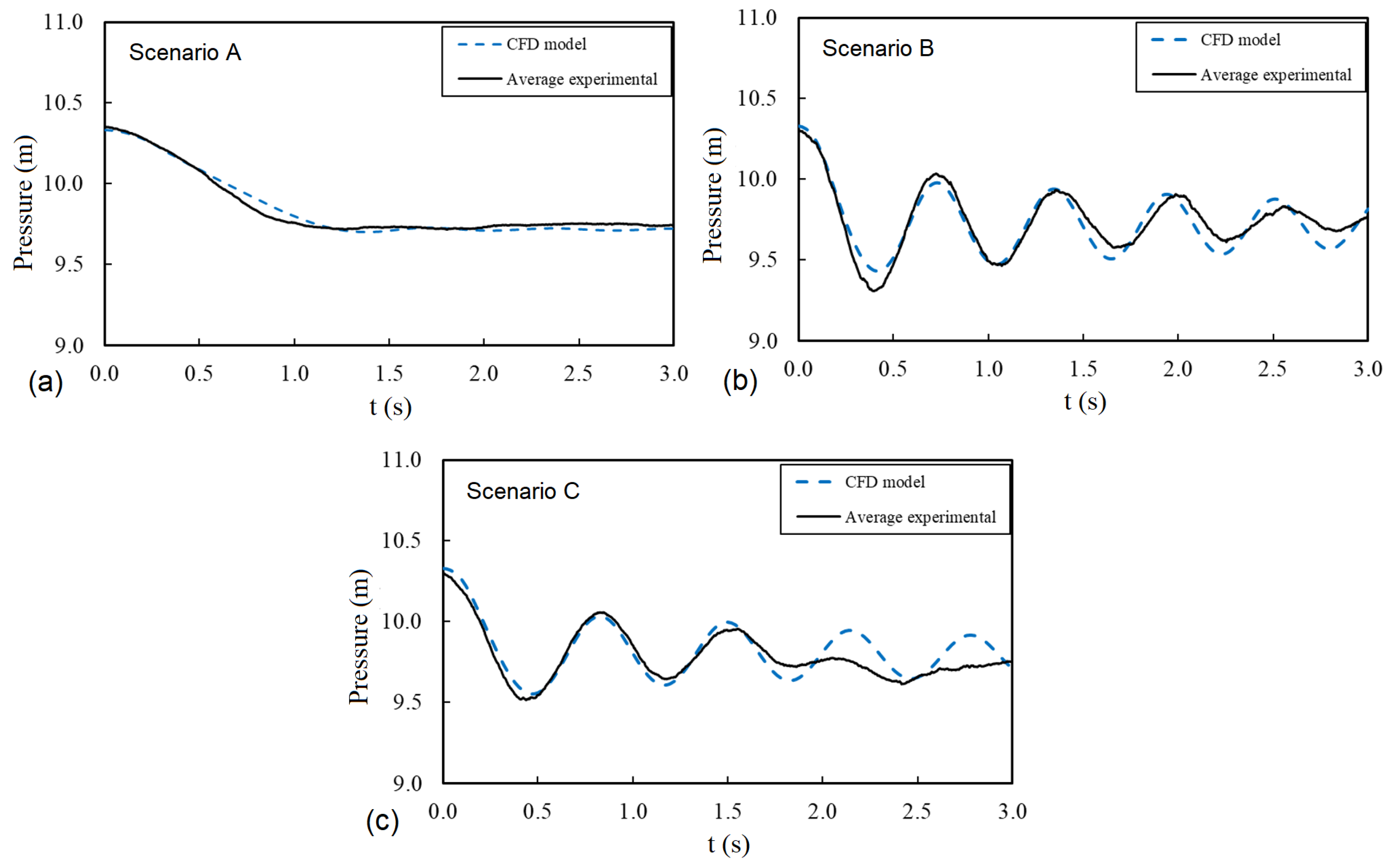
Figure 9 presents the schematics of an undulating pipeline without air valve protection. In this system, water can be drained through both ends of the line simultaneously. Additionally, the draining control valves may be opened either partially or totally. Three scenarios are discussed here: Scenario A with an equally distributed air pocket and partial opening of the valve; Scenario B with an equally distributed air pocket and total opening of the valve; and Scenario C with an unequally distributed air pocket and total opening of the valve. The equal or unequal distribution of the air pocket refers to the air pocket length in each individual pipe segment. To clarify what exactly happens during line draining, experimental tests and CFD simulations were carried out. For drainage without air valve protection, the CFD modelling was carried out with the use of ANSYS Fluent. A triangular unstructured mesh was used. For turbulence modelling, the κ ϵ turbulent model was considered. Additional information such as the valve manoeuvre was introduced into the simulation using relevant user-defined functions (UDF).
The pressure oscillation pattern is different for each scenario, as shown in Figure 10. As soon as the draining starts, the trapped air pocket begins to expand while its pressure decreases. The pressure graphs in Figure 10 clearly show that a pressure drop occurs soon after the start of the draining process. The comparison between Scenario A (Figure 10a) and Scenario B (Figure 10b) shows that the total opening of the control valve in Scenario B would cause a considerable and abrupt pressure drop, while the partial opening of the control valve in Scenario A would cause a milder drop. Furthermore, unequal air pocket distribution results in air pocket oscillation during the draining process, which increases the interaction between the air and water phases. Such an oscillation is also responsible for higher energy dissipation due to friction. As a result, pressure damping occurs faster for Scenario C (Figure 10c) than for Scenario B (Figure 10b).
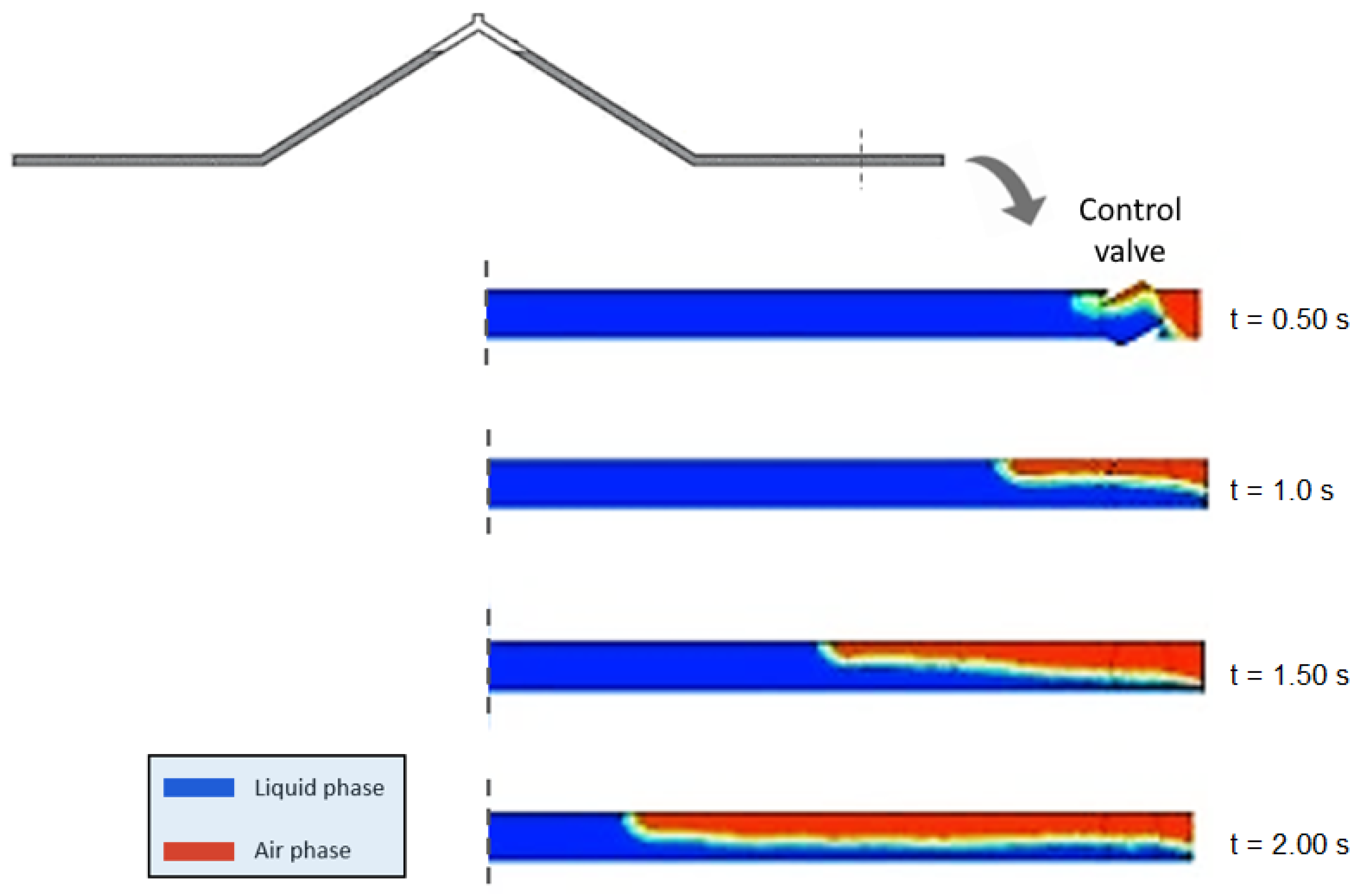
As noticed, backflow air intrusion is mainly triggered by the establishment of a sub-atmospheric pressure condition inside the trapped air pocket. In that sense, no air pocket intrusion has occurred in Scenario A, while air pocket intrusion has been quite considerable in the other two scenarios. Figure 11 shows that the backflow air intrusion starts around 0.5 s after the initiation of the emptying process in Scenario B. The backflow air intrusion is considerable in Scenario C as well. More air is admitted in Scenario C than in Scenario B because of the back and forth movement of the air–liquid interfaces in Scenario C (with an unequally distributed air pocket). A typical flow pattern forms during the draining operation as a result of the backflow air intrusion: a mixed two-phase flow comprises three distinct zones, namely a backflow air phase zone at the top, a mix eddy zone at the middle, and a liquid phase outflow at the bottom—such flow pattern can be observed in Figure 11 and Figure 12. As the draining process progresses, air continues to enter the pipeline at its downstream end until the water column is completely drained. The key parameter for design is the intensity of the pressure drop associated with a given draining operation. Previous studies [27,38] show that the worst sub-atmospheric pressure drop that occurs during a gravity-induced draining operation is a function of air pocket size and control valve manoeuvre. For instance, a small air pocket can lead to a dramatic pressure drop when a full opening of the control valve is performed rapidly. The magnitude of the sub-atmospheric pressure drop influences the backflow air intrusion process. The first pressure peak of the oscillation pattern is affected by the backflow air intrusion and the oscillation of the trapped air pocket.

3. Air Valves for Air Management in Pressurized Lines

3.1. Intake and Expulsion of Air

The flow of any gas or vapour through an orifice is practically adiabatic since the time required for each fluid element to pass through the nozzle is too short to allow for significant heat transfers; in addition, if the flow is assumed to be (essentially) frictionless, then the expansion that the fluid undergoes can be classified as isentropic. Starting from this hypothesis, it is possible to analytically determine the characteristic equations that model the operation of an air valve, both in the intake and expulsion regimens [39]. For air intake, if the absolute pressure inside the pipe satisfies 0.528 p atm * < p t * < p atm * (with p atm * as the absolute atmospheric pressure and p t * as the absolute air pressure inside the pipe), then the flow is subsonic, and the flow rate (both volumetric and mass rates) increases as the pressure inside the pipe decreases. For p t * 0.528 p atm * , however, a sonic condition is reached and the flow is choked, so that both volumetric and mass flow rates remain constant despite further decreases in internal pressure. Taking as the standard value for atmospheric pressure p atm * = 1.013 bar and considering Δ p = p atm * p t * for admission, the following limits are found: Δ p < 0.48 bar for the subsonic inflow and Δ p 0.48 bar for the sonic inflow. For air expulsion, while p atm * < p t * < 1.893 p atm * , the flow is subsonic, and volumetric and massic flow rates increase as the pressure inside the pipe increases. However, when p t * 1.893 p atm * , the flow becomes sonic, i.e., the volumetric flow remains constant (as long as the air temperature inside the pipe remains constant, which is usually adopted as a hypothesis), while the mass flow increases with increments of p t * (the air density inside the pipe increases with p t * increments). Considering again p atm * = 1.013 bar, but Δ p = p t * p atm * for expulsion, the boundary between subsonic and sonic flows is defined by Δ p < 0.90 bar for the subsonic outflow and Δ p 0.90 bar for the sonic outflow. More specifically, the following expressions (isentropic air flow equations) model the mass flow through an air valve [40]:
d m d t = C adm A adm 0.686 R T atm p atm * = constant for p t * 0.528 p atm *
d m d t = C adm A adm 7 p atm * ρ atm p t * p atm * 1.4286 p t * p atm * 1.714 for 0.528 p atm * < p t * < p atm *
d m d t = C exp A exp p t * 7 R T t p atm * p t * 1.4286 p atm * p t * 1.714 for p atm * < p t * < 1.893 p atm *
d m d t = C exp A exp 0.686 R T t p t * for p t * 1.893 p atm *
where d m / d t is the air mass flow rate, A adm and A exp are respectively the inflow and outflow air exchange areas, and C adm and C exp are respectively the inflow and outflow discharge coefficients (such coefficients are always less than the unit).
As an alternative to Equations (1)–(4), the incompressible model, in principle, can be used for relatively reduced differential pressures across the air valve [14,41]. The incompressible model conforms relatively well with experimental characterization data of air valves and is given by the following expressions [14]:
Q std = K for Δ p = p atm * p t * 0.48 bar
Q std = c adm p atm * Δ p for Δ p = p atm * p t * < 0.48 bar
Q std = c exp p t * Δ p for Δ p = p t * p atm * < 0.90 bar
Q std = K p t * for Δ p = p t * p atm * 0.90 bar
where Q std is the air flow at standard conditions, K and K are respectively coefficients associated with the sonic inflow and outflow, and c adm and c exp are respectively coefficients associated with the subsonic inflow and outflow.

3.2. Characteristic Curves of Air Valves

Characteristic curves of air valves are graphical representations of air valve behaviour usually provided by manufacturers in their catalogues. Each air valve model and size has an associated characteristic curve for admission and another for expulsion. Such curves show the relationship between air flow rate and differential pressure across the device. The characteristic curves of a given air valve model and size should ideally be obtained by testing the device in all operating regions (sonic and subsonic inflow, subsonic and sonic outflow). Mathematical models of air valve behaviour (mathematical representations of characteristic curves, such as Equations (1)–(4) or Equations (5)–(8)) can be fitted to characterization data. Unfortunately, product catalogues usually do not report in sufficient detail the experimental conditions employed in characterization tests, which undermines to at least some extent the reproducibility and reliability of the test results.
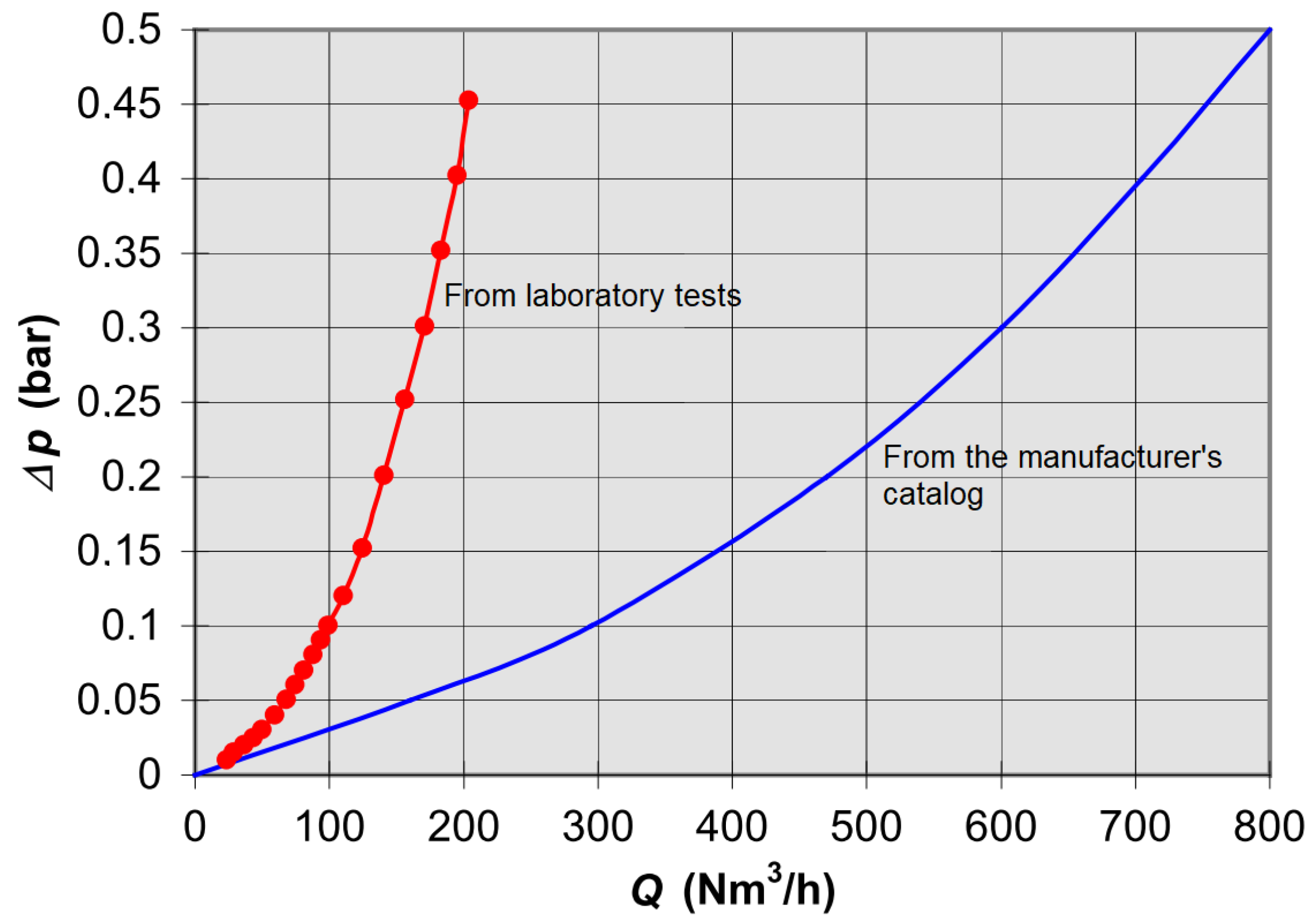
In fact, characterization data from tests carried out by third party laboratories show important discrepancies in relation to the data provided by manufacturers [14,17]. At the Polytechnic University of Valencia, for example, characterization tests were carried out in 1998 for many air valves, with results similar to those of other laboratories but with important discrepancies in relation to catalogue data [18]. Figure 13 shows two different curves related to the same air valve with a nominal diameter of 2 inches (50 mm). The curve obtained through static measurements at the Polytechnic University of Valencia differs notably from the manufacturer’s curve. The air valve capacity according to the manufacturer is almost four times larger than the measured capacity. This could introduce issues during pipeline filling operations. For pipeline draining, for example, a discrepancy of such a magnitude would result in pressure drops in the field much more intense than the ones obtained through numerical simulations using the inaccurate air valve curve.
In addition, manufacturers rarely give the air flow conditions that are conducive to air valve premature closure during outflow (“dynamic closure”). Such a phenomenon is common for air/vacuum valves. In fact, some air valve models can close prematurely for quite reduced values of differential pressure [17,20]. The speed of air circulation during expulsion can create a “sustaining effect” on the float of an air valve. As air moves through the valve during expulsion, a region of increased pressure is formed under the float, while a region of decreased pressure is located between the float and the outlet orifice [20]. A sufficiently fast stream of air moving through the air valve may cause the lifting force acting on the float to overcome its weight, resulting in the premature closing of the valve, leaving a potentially dangerous air pocket inside the pipeline.

3.3. The Use of the M51 Manual for Air Valve Application

The M51 manual by the American Water Works Association (AWWA) is an important reference for practitioners in relation to air valves in pressurized piping systems [2]. The first version of the manual was released in 2001, and in 2016, the second and currently latest version was released. The M51 manual seeks to give a “basic understanding” of air valve application for the protection of piping systems. M51 chapters overview the following aspects of air valve application: air pocket formation and accumulation, types of air valves and associated optional devices, air valve positioning along pipelines, air valve selection and sizing, the role of air valves during unsteady flows, and air valve installation and maintenance [11,42]. Considerable updates and improvements were made in the latest version of the manual. The current manual acknowledges the relevance of pipeline flow velocity for the hydraulic removal of air from downward segments with the presentation of an inclination and pipe diameter versus critical velocity table (“scouring velocity”). The manual increased the number and range of air valve design conceptions presented with several examples of air valves to be used in wastewater applications. The current manual also includes several design conceptions of optional devices for air valve functioning under water hammer events, such as throttling and slow closing devices. The previously assumed 0.7 discharge coefficient in the sizing tables was changed to 0.6. The manual indicates more details for the sizing of air valves with the inclusion of the situation of a pipeline partial rupture. The manual now also gives various detailed examples of vaults for air valves for above- or below-ground applications [43]. As a companion reference document to the M51 manual comes the ANSI/AWWA C512 standard regarding the minimum requirements for air valves in water and wastewater applications. Several versions of this standard have been released, namely in 1992, 1999, 2004, 2008, and 2015 [44,45,46,47,48]. Throughout the years, the C512 standard increased in length and became more comprehensive. The C512-07 version of the standard includes in its foreword the role of air valves as protection devices against water column separation. Furthermore, such instalment of the standard includes specifications regarding the minimum requirements for throttling or slow closing devices. The current version of the C512 standard includes in its title the reference to wastewater applications for air valves [43].
M51 recommends that air valves be installed at all high points. M51 also recommends that air valves be periodically spaced about every 600 m—of course, more details in this regard should be consulted in the manual itself. The air valve recommendations given by the manual in relation to air valve positioning, however, could lead to an abundance of installed devices [49]. However, the maintenance of hard-to-access air valves is often neglected in practice [2]. Leaky air valves due to a lack of periodical maintenance become paths to water leakage or the entrance of contaminants [50]. The sizing criteria given by the manual are separated into sections, namely the sizing of air-release valves and the sizing of air valves for filling, draining, gravity flow, and pipe rupture. The manual also recommends the use of numerical simulations to evaluate the behaviour of air valves during transient events. Thus, air valves are required to satisfy a varied set of loading conditions. The suggested assumptions for the sizing of air-release valves according to M51 can potentially result in oversized valves [49,51,52]. In the sizing process, the necessary orifice for air inflow due to a line rupture (usually a large orifice) is often in conflict with the ideal orifice size for filling, draining, or air expulsion during transient events (usually a small orifice) [43]. Ramezani and Daviau (2021) [53], for example, explore, with a practical example, the importance of using air valves with anti-slam systems for line protection in the context of pump trip scenarios. However, reduced outflow orifices, adequate for air valve functioning in the context of water hammer events, such as pump trips, for example, might be insufficiently sized for line filling scenarios.
M51 recommends that the filling process must be carried out with special care to avoid undesirably intense pressure surges, i.e., with slow valve manoeuvres that result in a gentle expulsion of the entrapped air. A differential pressure of 2 psi (13.8 kPa) is recommended during this process for regular air valves. The water filling discharge must match the outflow of air, maintaining a water filling velocity under 0.3 m/s [11]. In fact, extreme pressures are not only dependent on the filling velocity and air valve size but also on a variety of system conditions, such as the presence of other protection devices, pipe material, wall thickness, altimetric profile disposition, and pipeline length [10,54]. According to Coronado et al. (2018) [55], the main factors that influence the intensity of up-surges during line filling are pipe slope, air valve size, internal diameter, and friction factor. Operational procedures to achieve a reduced filling velocity might be difficult to achieve in practice given the unsteady nature of filling operations in undulating pipelines [56]. During line emptying, the drained water must be continually replaced by incoming air to avoid excessive drops in pressure. For draining, the manual recommends water discharge velocities of no more than 0.3 to 0.6 m/s and a differential pressure of 5 psi (34.5 kPa)—or a differential pressure in accordance with the pipeline resistance to vacuum conditions. If a system does not have air valves or if its air valves are undersized, then pressure drops can be large, and the installation may actually be incompletely drained. According to Coronado et al. (2018) [55], the main factors that influence the intensity of down-surges during line draining are air valve size, air pocket size, pipe slope, and internal pipe diameter. Aguirre et al. (2022) [57] studied the relevance of air valves during uncontrolled filling processes and concluded that pipeline filing must be done according to manuals or internal practices to avoid excessively intense secondary pressures originating from an air valve closure.
Ramezani (2015) [58] completed a parametric study to evaluate the relative importance of key air valve and pipeline parameters on the magnitude of secondary pressures in pipelines subject to under-pressure events. The study showed that the air valve inflow capacity and initial water discharge are the most influential parameters in relation to extreme negative transient pressures, while the air valve outflow capacity and initial water discharge are the most influential parameters in relation to extreme positive transient pressures [58]. Ramezani and Karney (2017) [54] developed semi-analytical equations to model the pressure surges from a down-surge event in a pipeline with a distinct high point with an air valve (a situation analogous to a pump trip scenario). In the study developed by Ramezani and Karney (2017) [54], however, the air valve is assumed to admit and expel air freely; thus, the influence of the air valve itself could not be assessed. Nevertheless, these researchers found that the downstream branch of the pipeline (after the air valve at the high point) was a determining factor in the formation of the transient air pocket and the intensity of secondary pressure waves. Higher elevations of the high point are conducive to longer transient processes and larger volumes of admitted air. It was found that the maximum pressure spike upon the air valve closure increases as the elevation of the high point increases. The research conducted by Tasca et al. (2021) [10] shows that air valve capacity indeed has an influence on the magnitude of secondary pressure waves and the associated maximum transient pressures in the system during pump trip scenarios. According to Tasca et al. (2021) [10], considering incorrect values of discharge coefficients in numerical simulations can lead to errors in the numerical results.
In summary, the M51 manual offers insightful and useful information regarding the application of air valves. It is advisable, however, that practitioners consider a broader variety of reference materials when dealing with air issues in pressurized piping systems. As pointed out by Tasca et al. (2022) [43], there is still a disconnect between the M51 manual and the most up-to-date scientific developments in the fields of two-phase flows and air valve application and modelling. This is evinced, for example, by the fact that a substantial part of the documents cited as references by the manual is from before 1990 [11].

4. Macro-Cavitation and Air Exchanges through Air Valves during Unsteady Flows

Excessively intense transient pressures can cause the rupture of hydraulic systems, while excessively low pressures can lead to pipe collapse, entry of air or pollutants, release of dissolved air, or the formation of vapour cavities. Common sources of severe hydraulic transients include pump trips, load rejection in hydropower plants, sudden valve operations, and a failure of control devices or a line burst, not to mention line filling and draining. Limiting extreme transient pressures is necessary to avoid system failure, to improve operational efficiency, and to avoid system fatigue [5]. In this section, two important aspects of two-phase flows in pressurized pipeline systems, macro-cavitation and air exchanges through air valves, are explored with numerical analyses of practical examples.
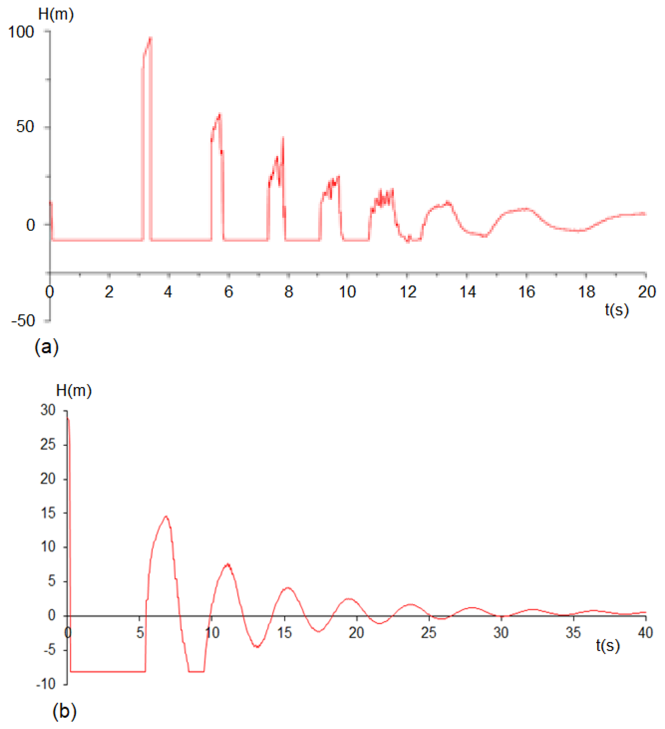
Tractive stresses may arise in the water phase contained in a piping system if pressure levels drop to a certain threshold, namely the vapour pressure of water, which is often (in cold water supply lines) rather close to absolute zero pressure. Such a threshold might be reached, for example, due to pressure down-surges from pump trips or valve manoeuvres. Vacuum conditions in piping systems can lead to water column separation, air release, and vapour formation at the upper part of conduits or at high points. In the event of water column separation, vapour is released from the water phase to occupy the cavity between such columns and to avoid pressure levels from going below the threshold limit (assuming adequate nucleation sites are available, which is usually the case). However, once pressure levels are reestablished, the previously separated water columns rejoin, and the vaporous cavity can rapidly disappear. Such cavity collapse results in a possibly dangerous pressure spike [40]. It should be noted that air exchange is asymmetrical, with its release from the solution much faster than its subsequent dissolution. Because of this, the pressure rise due to a cavity collapse is partially dampened by the cushioning effects of undissolved free gas [59,60]. Cavities formed from water column separation in the context of macro-cavitation are generally assumed to be localized. In terms of modelling, it is usual (and a conservative analysis) to neglect the effect of air release upon cavity formation, and the possibility of a cavity is admitted in all calculation sections. In this way, macro-cavitation can be characterized by the existence of a volume of vapour that will be obtained through the continuity equation. Importantly, the system response to macro-cavitation is dependent on pipe material [61,62]. Figure 14 highlights the difference in the system transient behaviour between two pipes: a metal pipeline and plastic pipeline. The piezometric variation in Figure 14 is characterized by a minimum pressure, corresponding to the vapour pressure of the liquid, with a negative relative pressure (near the vacuum) and constant value, followed by extreme spikes, which might induce the rupture of the piping system if too intense. Note in Figure 14 how the pressure spikes in the metallic pipe (Figure 14a) are much more intense than those in the plastic pipe (Figure 14b). Additionally, the pressure oscillations in the case with the plastic pipeline are smoother and with a longer period than in the case with the metallic pipeline. The characteristics of pressure oscillations during down-surge events are also dependent on the pipeline profile, horizontal and vertical position of the air valve, air valve size, and water discharge during steady flow conditions [10,54].
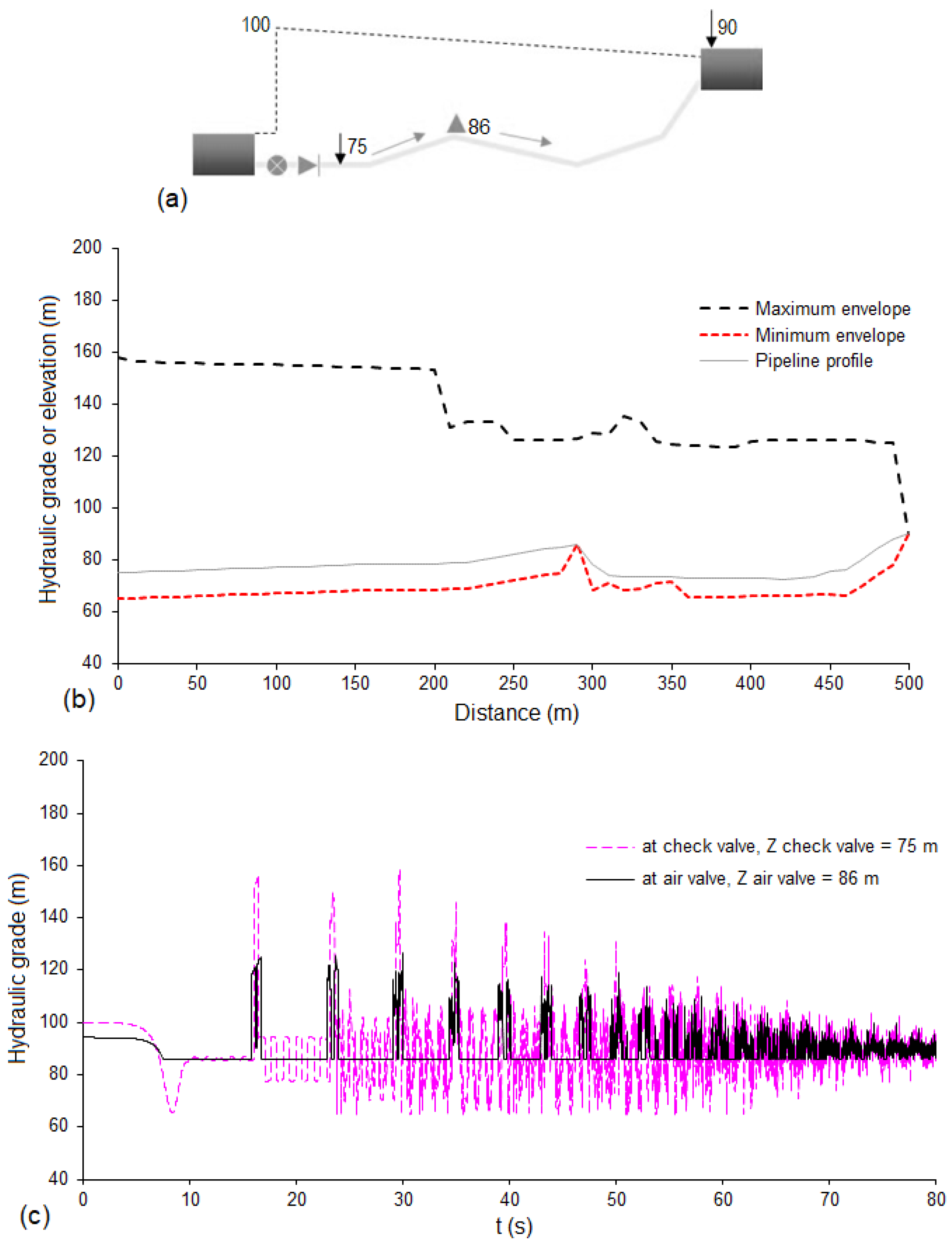
Knowledge relating to the pipeline profile is fundamental to the analysis of hydraulic transients. High points, in particular, can be critical sections for the occurrence of macro-cavitation and, therefore, preferential locations for the installation of air valves, which allow for the entry of atmospheric air, thus preventing the fluid pressure from reaching the vaporization threshold, which would result in the formation of vapour bubbles or even water column separation. Sometimes, however, the exact altimetric disposition of a pipeline is not entirely known, a situation that can arise in several ways: construction that does not exactly follow design specifications, a lack of records of the pipeline “as built”, and construction specifications that give to contractors some margin of “interpretation”, such as simply setting a minimum coverage for the pipeline in relation to the terrain grade [25]. Nevertheless, in a pumping system such as the one depicted in Figure 15a, an air valve installed at the high point of the profile limits the minimum piezometric head at the air valve location, simultaneously limiting the maximum overpressure in the neighbourhood of the air valve [10]. The graphs in Figure 15b,c show numerical analysis regarding a pump trip scenario for the water rising line depicted in Figure 15a. The following assumptions are considered in the numerical simulations: a pipeline length of 500 m, pipe diameter of 0.1 m, distance of 290 m between the air valve and the upstream reservoir, celerity of propagation of pressure waves of 1000 m/s, closure of the upstream check valve in 10 s, and initial water discharge of 0.01 m 3 /s. As evinced by the minimum head envelope in Figure 15b, which shows that the whole pipeline experienced negative pressures during the transient event, small differences between upstream and downstream reservoirs are problematic in relation to the occurrence of cavitation. As presented in Figure 15c, at the check valve, right downstream of the pump, the maximum hydraulic grade increased by about 60% in relation to the steady flow situation due to the pump trip scenario. At the air valve, however, the extreme hydraulic grade surge due to the pump trip only surpassed the steady flow value by about 30%.

5. Discussion

Two-phase flows complicate the response of hydraulic systems during water hammer events. In particular, unmanaged entrapped air can substantially increase the likelihood of misbehaviours or even induce serious accidents. The overview presented in this paper, supported by results from experimental tests and numerical analyses, focuses on the dynamic characteristics of two-phase flows in hydraulic systems containing air. It was found that the dynamic response of a system containing air to a pressurization event is sensitive to pressurization load, trapped air volume, orifice diameter (in the case of a vented system), and initial air pocket pressure. Initial air pocket pressure was found to be a crucial determinant of the dynamic interaction between fluids: even a reduced initial “pre-pressurization” level in the system may constitute a relevant preventive measure for the mitigation of air-related deleterious dynamic effects. The current study also shows that air pocket size and location have a significant influence on the system transient response during a pressurization scenario. Moreover, in a filling operation, the diameter of the downstream orifice for air release significantly affects the magnitude of the local impact speed of the water front upon air release completion.
Air valves are a key means to limiting and controlling the presence of air and misbehaviours associated with entrapped air in pipeline systems. Air valves are installed in pipelines to prevent excessive overpressures by expelling air (during filling processes or hydraulic transients) and to prevent major down-surges by sufficiently admitting air (during emptying processes or hydraulic transients). Such devices, when well-designed and maintained, can help to reduce extreme transient pressures. If poorly sized, however, such devices can be linked to the formation of extreme transient pressures possibly higher than those attained in the absence of air venting. In summary, improperly selected or maintained air valves can lead to undesirable or even catastrophic system behaviour. Properly sizing air valves, however, does not come without its challenges: characteristic curves provided by manufacturers, essential information for the assessment air valve capacity, are often not representative of actual air valve behaviour. In fact, real characteristic curves of air valves, as obtained in laboratory tests, often do not coincide with the curves provided by the manufacturers. Therefore, it is advisable to take precautions when using air valve capacity information found in product catalogues. In some instances, real air valve capacity can be notably lower than what is indicated in manufacturer catalogues. Considering an overestimated air valve capacity during design could lead to potentially serious issues in the context of draining operations. Neglecting the occurrence of air valve dynamic closure in the context of air expulsion could also lead to issues. Ideally, characteristic curves should be obtained through controlled experimental tests. However, this is often not feasible in practice. Thus, some sort of safety factor should be considered in design if actual air valve behaviour is uncertain.

6. Conclusions

Control of air, and air–water interactions, is of crucial importance for the effective management of pressurized pipeline systems. The presence of uncontrolled air movement, or unmanaged trapped air, in pressurized hydraulic systems can lead to inefficiency and, more importantly, to potentially dangerous misbehaviours. The central conclusions that can be derived from the current investigation are listed in the following:
  • Pipeline profile—characteristics of high points and inclination of pipes—is highly influential on the proclivity of a system towards air-related issues. It should be emphasized that small elevation differences between upstream and downstream reservoirs result in pressure control issues with a high probability for the occurrence of cavitation during unsteady flow scenarios.
  • In the presence of air, the amplitudes of transient pressure oscillations were shown to be consistently higher than those registered with the complete filling of the conduit with water, with a degree of amplification that was found to be a function of the initial conditions of the entrapped air (volume and pressure) and the hydraulic load in the pressurization source.
  • Higher loads in the pressurization source caused oscillations of greater amplitude and frequency. The initial air pressure also considerably affects the magnitude and frequency of oscillations. As initial air pressure increases, so does the attenuation of transient pressure oscillations.
  • The level of amplification, defined in relation to the reference response of the system when only containing water, proved to be greatest under the highest pressurization loads, also being determined by initial air volume and pressure. The amplifications of the tests with trapped air initially at atmospheric pressure varied between about 30% and 200%. Under a higher initial air pressure, the amplification of the pressure fluctuations is considerably reduced.
  • The behaviour of the air–water interface is strongly affected by the initial characteristics of the air pocket and also by the initial load differential in the system, presenting a strong disturbance for large initial volumes of trapped air.
  • The presence of any type of orifice in hydraulic systems makes them susceptible to significant transient oscillations, especially in the presence of small volumes of entrapped air and for large orifice dimensions.
  • The selection of an air valve orifice for expulsion must consider different sizing aspects. If the air valve is too small, then it is not able to expel the required amount of air, and significant overpressures could be generated. If the air valve has been oversized and is too large, the expelled flow rates are very intense and can generate large overpressures upon air valve closure, even higher than if such a valve was not installed.
  • Another important issue in the selection of air valves is the “dynamic closure” that occurs when the float closes prematurely, that is, before the arrival of the water column. When an air valve closes without having completely expelled all the entrapped air, the water column compresses the remaining residual air, producing significant overpressures. Most air/vacuum valves suffer from this issue. However, manufacturers usually do not provide useful information about the dynamic closure of air valves.
  • During the emptying process, air valves are selected to protect the installation against possible sub-atmospheric pressures. In this case, the larger the air valve, the greater the intake capacity and the smaller the down-surge produced. However, these same valves will be present for other conditions that might be in conflict with the draining requirements.
In summary, the selection of air valves requires the adherence to several precautions: be careful not to oversize valves, accept characteristic curves found in catalogues only with a degree of suspicion, be aware of the issue of “dynamic closure” during air expulsion, be alert that internal valve construction can complicate any simplistic selection according to the nominal diameter only, and be alert that all mechanical devices, especially air valves, require periodical maintenance.

Author Contributions

Conceptualization, H.M.R. and V.S.F.-M.; methodology, H.M.R., V.S.F.-M., O.E.C.-H. and M.B.; validation, H.M.R., V.S.F.-M., O.E.C.-H. and M.B.; formal analysis, H.M.R., V.S.F.-M., O.E.C.-H. and M.B.; investigation, H.M.R., V.S.F.-M., E.T., O.E.C.-H. and M.B.; resources, H.M.R. and V.S.F.-M.; data curation, H.M.R., V.S.F.-M., E.T., O.E.C.-H. and M.B.; writing—original draft preparation, H.M.R., V.S.F.-M. and E.T.; writing—review and editing, H.M.R., V.S.F.-M., E.T., O.E.C.-H., M.B., L.Z. and B.K.; supervision, H.M.R., V.S.F.-M. and B.K. All authors have read and agreed to the published version of the manuscript.

Funding

This work was supported by Fundação para a Ciência e a Tecnologia [grant number SFRH/BD/39502/2007]. This study was financed in part by the Coordenação de Aperfeiçoamento de Pessoal de Nível Superior—Brasil (CAPES)—Finance Code 001.

Acknowledgments

The authors acknowledge the support from the Civil Engineering Research and Innovation for Sustainability (CERIS), Instituto Superior Técnico (IST), University of Lisbon (Portugal).

Conflicts of Interest

The authors declare no conflict of interest.

References

  1. Lauchlan, C.S.; Escarameia, M.; May, R.W.P.; Burrows, R.; Gahan, C. Air in Pipelines: A Literature Review; HR Wallingford: Oxfordshire, UK, 2005. [Google Scholar]
  2. Ramezani, L.; Karney, B.; Malekpour, A. The challenge of air valves: A selective critical literature review. J. Water Resour. Plann. Manag. 2015, 141, 04015017. [Google Scholar] [CrossRef]
  3. Ramezani, L.; Karney, B.; Malekpour, A. Encouraging effective air management in water pipelines: A critical review. J. Water Resour. Plann. Manag. 2016, 142, 04016055. [Google Scholar] [CrossRef] [Green Version]
  4. Martins, S.C. Dinâmica da Pressurização de Sistemas Hidráulicos Com ar Aprisionado. Ph.D. Thesis, Instituto Superior Técnico, Universidade Técnica de Lisboa, Lisbon, Portugal, 2013. [Google Scholar]
  5. Tullis, J.P. Hydraulics of Pipelines: Pumps, Valves, Cavitation, Transients; John Wiley & Sons: New York, NY, USA, 1989. [Google Scholar]
  6. Boulos, P.; Karney, B.; Wood, D.; Lingireddy, S. Hydraulic transient guidelines for protecting water distribution systems. J. Am. Water Work. Assoc. 2005, 97, 111–124. [Google Scholar] [CrossRef]
  7. Pothof, I.; Karney, B. Guidelines for transient analysis in water transmission and distribution systems. In Water Supply System Analysis–Selected Topics; Ostfeld, A., Ed.; InTech: Rijeka, Croatia, 2012; pp. 1–21. [Google Scholar]
  8. Zhou, L.; Liu, D.; Karney, B. Investigation of hydraulic transients of two entrapped air pockets in a water pipeline. J. Hydraul. Eng. 2013, 139, 949–959. [Google Scholar] [CrossRef]
  9. Coronado-Hernández, O.E.; Fuertes-Miquel, V.S.; Besharat, M.; Ramos, H.M. Experimental and numerical analysis of a water emptying pipeline using different air valves. Water 2017, 9, 98. [Google Scholar] [CrossRef]
  10. Tasca, E.S.A.; Karney, B.; Luvizotto, E., Jr. Performance similarity between different-sized air exchange valves. J. Hydraul. Eng. 2021, 147, 04021036. [Google Scholar] [CrossRef]
  11. American Water Works Association (AWWA). Manual of Water Supply Practices M51–Air Valves: Air-Release, Air/Vacuum and Combination, 2nd ed.; AWWA: Denver, CO, USA, 2016. [Google Scholar]
  12. Zhou, L.; Wang, H.; Karney, B.; Liu, D.; Wang, P.; Guo, S. Dynamic behavior of entrapped air pocket in a water filling pipeline. J. Hydraul. Eng. 2018, 144, 04018045. [Google Scholar] [CrossRef]
  13. Malekpour, A.; Karney, B.; Nault, J. Physical understanding of sudden pressurization of pipe systems with entrapped air: Energy auditing approach. J. Hydraul. Eng. 2016, 142, 04015044. [Google Scholar] [CrossRef] [Green Version]
  14. Fuertes-Miquel, V.S.; Iglesias-Rey, P.L.; Izquierdo-Sebastián, J.; López-Patiño, G. Algunos problemas generados por ventosas mal seleccionadas a causa de una caracterización hidráulica errónea. In Proceedings of the XXII Congreso Latinoamericano de Hidráulica, Ciudad Guayana, Venezuela, 12–13 October 2006. [Google Scholar]
  15. Lingireddy, S.; Wood, D.J.; Zloczower, N. Pressure surges in pipeline systems resulting from air releases. J. Am. Water Work. Assoc. 2004, 96, 88–94. [Google Scholar] [CrossRef]
  16. Tasca, E.S.A.; Dalfré Filho, J.G.; Luvizotto, E., Jr.; Aquino, G.A. The problem of air valves inaccurate air mass flow versus differential pressure curves. In Proceedings of the 1st International WDSA/CCWI Joint Conference, Kingston, ON, Canada, 23–25 July 2018. [Google Scholar]
  17. Iglesias-Rey, P.L.; Fuertes-Miquel, V.S.; García-Mares, F.J.; Martínez-Solano, J.J. Comparative study of intake and exhaust air flows of different commercial air valves. Procedia Eng. 2014, 89, 1412–1419. [Google Scholar] [CrossRef] [Green Version]
  18. Fuertes-Miquel, V.S. Hydraulic Transients with Entrapped Air Pockets. Ph.D. Thesis, Department of Hydraulic Engineering, Polytechnic University of Valencia, Valencia, Spain, 2001. [Google Scholar]
  19. Iglesias-Rey, P.L.; García-Mares, F.J.; Fuertes-Miquel, V.S.; Martínez-Solano, F.J. Air valves characterization using hydrodynamic similarity. In Proceedings of the World Environmental and Water Resources Congress 2017, Sacramento, CA, USA, 21–25 May 2017. [Google Scholar]
  20. García-Todolí, S.; Iglesias-Rey, P.L.; Mora-Meliá, D.; Martínez-Solano, F.J.; Fuertes-Miquel, V.S. Computational determination of air valves capacity using CFD techniques. Water 2018, 10, 1433. [Google Scholar] [CrossRef] [Green Version]
  21. Escarameia, M. Investigating hydraulic removal of air from water pipelines. Water Manag. 2007, 160, 25–34. [Google Scholar] [CrossRef]
  22. Pothof, I.; Clemens, F. Experimental study of air-water flow in downward sloping pipes. Int. J. Multiph. Flow 2011, 37, 278–292. [Google Scholar] [CrossRef]
  23. Pothof, I.; Clemens, F. On elongated air pockets in downward sloping pipes. J. Hydraul. Res. 2010, 48, 499–503. [Google Scholar] [CrossRef]
  24. Zheng, G.; Brill, J.P.; Taitel, Y. Slug flow behavior in a hilly terrain pipeline. Int. J. Multiph. Flow 1994, 20, 63–79. [Google Scholar] [CrossRef]
  25. Edmunds, R.C. Air binding in pipes. J. Am. Water Work. Assoc. 1979, 71, 272–277. [Google Scholar] [CrossRef]
  26. Pozos, O.; Gonzalez, C.A.; Giesecke, J.; Marx, W.; Rodal, E.A. Air entrapped in gravity pipeline systems. J. Hydraul. Res. 2010, 48, 338–347. [Google Scholar] [CrossRef]
  27. Besharat, M.; Coronado-Hernández, O.E.; Fuertes-Miquel, V.S.; Viseu, M.T.; Ramos, H.M. Computational fluid dynamics for sub-atmospheric pressure analysis in pipe drainage. J. Hydraul. Res. 2020, 58, 553–565. [Google Scholar] [CrossRef]
  28. Zhou, L.; Liu, D.; Karney, B.; Zhang, Q. Influence of entrapped air pockets on hydraulic transients in water pipelines. J. Hydraul. Eng. 2011, 137, 1686–1692. [Google Scholar] [CrossRef] [Green Version]
  29. Zhou, L.; Liu, D.; Karney, B.; Wang, P. Phenomenon of white mist in pipelines rapidly filling with water with entrapped air pockets. J. Hydraul. Eng. 2013, 139, 1041–1051. [Google Scholar] [CrossRef]
  30. Martin, C.S.; Lee, N.H. Rapid expulsion of entrapped air through an orifice. In Proceedings of the 8th International Conference on Pressure Surges, The Hague, Netherlands, 12–14 April 2000. [Google Scholar]
  31. Zhou, F.; Hicks, F.E.; Steffler, P.M. Transient flow in a rapidly filling horizontal pipe containing trapped air. J. Hydraul. Eng. 2002, 128, 625–634. [Google Scholar] [CrossRef]
  32. Zhou, F.; Hicks, F.E.; Steffler, P.M. Observations of air-water interaction in a rapidly filling horizontal pipe. J. Hydraul. Eng. 2002, 128, 635–639. [Google Scholar] [CrossRef]
  33. Zhou, F.; Hicks, F.E.; Steffler, P.M. Analysis of effects of air pocket on hydraulic failure of urban drainage infrastructure. Can. J. Civ. Eng. 2004, 31, 86–94. [Google Scholar] [CrossRef]
  34. De Martino, G.; Fontana, N.; Giugni, M. Transient flow caused by air expulsion through an orifice. J. Hydraul. Eng. 2008, 134, 1395–1399. [Google Scholar] [CrossRef] [Green Version]
  35. Zhou, L.; Pan, T.; Wang, H.; Liu, D.; Wang, P. Rapid air expulsion through an orifice in a vertical water pipe. J. Hydraul. Res. 2019, 57, 307–317. [Google Scholar] [CrossRef]
  36. Zhou, L.; Cao, Y.; Karney, B.; Bergant, A.; Tijsseling, A.; Liu, D.; Wang, P. Expulsion of entrapped air in a rapidly filling horizontal pipe. J. Hydraul. Eng. 2020, 146, 04020047. [Google Scholar] [CrossRef]
  37. Coronado-Hernández, O.E.; Fuertes-Miquel, V.S.; Angulo-Hernández, F.N. Emptying operation of water supply networks. Water 2018, 10, 22. [Google Scholar] [CrossRef] [Green Version]
  38. Besharat, M.; Coronado-Hernández, O.E.; Fuertes-Miquel, V.S.; Viseu, M.T.; Ramos, H.M. Backflow air and pressure analysis in emptying a pipeline containing an entrapped air pocket. Urban Water J. 2018, 15, 769–779. [Google Scholar] [CrossRef]
  39. Fuertes-Miquel, V.S.; López-Jiménez, P.A.; Martínez-Solano, F.J.; López-Patiño, G. Numerical modelling of pipeline with air pockets and air valves. Can. J. Civ. Eng. 2016, 43, 1052–1061. [Google Scholar] [CrossRef] [Green Version]
  40. Wylie, E.B.; Streeter, V.L. Fluid Transients; FEB Press: Ann Arbor, MI, USA, 1983. [Google Scholar]
  41. White, F.M. Fluid Mechanics; McGraw-Hill: New York, NY, USA, 2011. [Google Scholar]
  42. American Water Works Association (AWWA). Manual of Water Supply Practices M51–Air-Release, Air/Vacuum, and Combination Air Valves, 1st ed.; AWWA: Denver, CO, USA, 2001. [Google Scholar]
  43. Tasca, E.S.A.; Karney, B.; Besharat, M.; Ramos, H.M.; Zhou, L. Insights and challenges associated with air in pressurized water conveyance systems. In Proceedings of the World Environmental and Water Resources Congress 2022, Atlanta, GA, USA, 5–8 June 2022. [Google Scholar]
  44. ANSI/AWWA. C512-92–Air-Release, Air/Vacuum, and Combination Air Valves for Waterworks Service; AWWA: Denver, CO, USA, 1992. [Google Scholar]
  45. ANSI/AWWA. C512-99–Air-Release, Air/Vacuum, and Combination Air Valves for Waterworks Service; AWWA: Denver, CO, USA, 1999. [Google Scholar]
  46. ANSI/AWWA. C512-04–Air-Release, Air/Vacuum, and Combination Air Valves for Waterworks Service; AWWA: Denver, CO, USA, 2004. [Google Scholar]
  47. ANSI/AWWA. C512-07–Air-Release, Air/Vacuum, and Combination Air Valves for Waterworks Service; AWWA: Denver, CO, USA, 2008. [Google Scholar]
  48. ANSI/AWWA. C512-15–Air-Release, Air/Vacuum, and Combination Air Valves for Water and Wastewater Service; AWWA: Denver, CO, USA, 2015. [Google Scholar]
  49. McPherson, D.L. Air valve sizing and location: A prospective. In Proceedings of the Pipelines 2009: Infrastructure’s hidden assets, San Diego, CA, USA, 15–19 August 2009. [Google Scholar]
  50. Besner, M.C.; Ebacher, G.; Jung, B.S.; Karney, B.; Lavoie, J.; Payment, P.; Prévost, M. Negative pressures in full-scale distribution system: Field investigation, modelling, estimation of intrusion volumes and risk for public health. Drink. Water Eng. Sci. 2010, 3, 101–106. [Google Scholar] [CrossRef] [Green Version]
  51. McPherson, D.L.; Haeckler, C. Untangling the mysteries of air valves. In Proceedings of the Pipelines 2012: Innovations in Design, Constructing, Operations, and Maintenance, Doing More with Less, Miami Beach, FL, USA, 19–22 August 2012. [Google Scholar]
  52. Beieler, R. What every conveyance designer should know about air valves and air valve assemblies. In Proceedings of the Pipelines 2016: Out of Sight, Out of Mind, Not Out of Risk, Kansas City, MO, USA, 17–20 July 2016. [Google Scholar]
  53. Ramezani, L.; Daviau, J. The challenge of air valve selection in pumping systems. In Proceedings of the Pipelines 2021, Online, 3–6 August 2021. [Google Scholar]
  54. Ramezani, L.; Karney, B. Water column separation and cavity collapse for pipelines protected with air vacuum valves: Understanding the essential wave processes. J. Hydraul. Eng. 2017, 143, 04016083. [Google Scholar] [CrossRef] [Green Version]
  55. Coronado-Hernández, O.E.; Fuertes-Miquel, V.S.; Besharat, M.; Ramos, H.M. A parametric sensitivity analysis of numerically modelled piston-type filling and emptying of an inclined pipeline with an air valve. In Proceedings of the 13th International Conference on Pressure Surges, Bordeaux, France, 14–16 November 2018. [Google Scholar]
  56. Fuertes-Miquel, V.S.; Coronado-Hernández, O.E.; Mora-Meliá, D.; Iglesias-Rey, P.L. Hydraulic modeling during filling and emptying processes in pressurized pipelines: A literature review. Urban Water J. 2019, 16, 299–311. [Google Scholar] [CrossRef]
  57. Aguirre-Mendoza, A.M.; Paternina-Verona, D.A.; Oyuela, S.; Coronado-Hernández, O.E.; Besharat, M.; Fuertes-Miquel, V.S.; Iglesias-Rey, P.L.; Ramos, H.M. Effects of orifice sizes for uncontrolled filling processes in water pipelines. Water 2022, 14, 888. [Google Scholar] [CrossRef]
  58. Ramezani, L. An Exploration of Transient Protection of Pressurized Pipelines Using Air Valves. Ph.D. Thesis, University of Toronto, Toronto, ON, Canada, 2015. [Google Scholar]
  59. Borga, A.; Ramos, H.M.; Covas, D.; Dudlik, A.; Neuhaus, T. Dynamic effects of transient flows with cavitation in pipe systems. In Proceedings of the 9th International Conference on Pressure Surges, Chester, UK, 24–26 March 2004. [Google Scholar]
  60. Ramos, H.M.; Borga, A.; Bergant, A.; Covas, D.; Almeida, A.B. Analysis of surge effects in pipe systems by air release/venting. Port. J. Water Resour. 2005, 26, 45–55. [Google Scholar]
  61. Ramos, H.M.; Covas, D.; Borga, A.; Loureiro, D. Surge damping analysis in pipe systems: Modelling and experiments. J. Hydraul. Res. 2004, 42, 413–425. [Google Scholar] [CrossRef]
  62. Ramos, H.M.; Borga, A. Surge effects in pressure systems for different pipe materials. In Advances in Water Resources and Hydraulic Engineering; Springer: Berlin/Heidelberg, Germany, 2009; pp. 2152–2156. [Google Scholar]
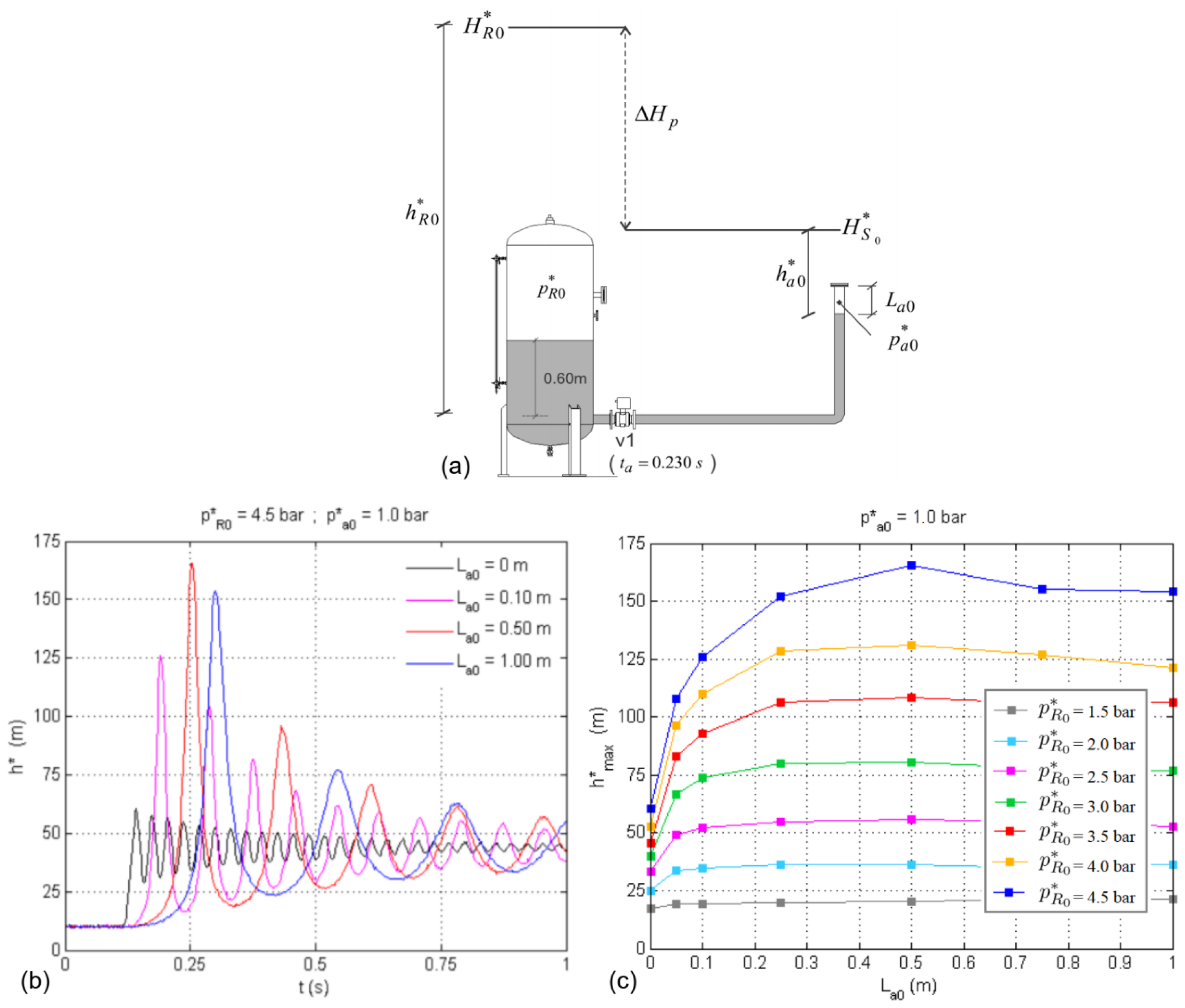
Figure 1. Pipeline filling tests for system with confined entrapped air pocket: (a) experimental apparatus; (b) piezometric head variation; (c) maximum piezometric head.
Water 14 02376 g001
Figure 2. Influence of initial air pocket pressure on the amplitude and frequency of pressure oscillations during pipeline filling.
Water 14 02376 g002
Figure 3. Maximum piezometric head differential versus initial load differential for different air pocket sizes and initial air pocket pressures for system subject to pipeline filling: (a) L a 0 = 0.05 m; (b) L a 0 = 0.10 m; (c) L a 0 = 0.25 m; (d) L a 0 = 0.50 m.
Water 14 02376 g003
Figure 4. Behaviour of air–water interface in vertical pipe segment during pipeline filling: (a) interface showing intense air–water mixture; (b) comparison between numerical and experimental results.
Water 14 02376 g004
Figure 5. Influence of orifice diameter on system transient behaviour during pipeline filling—the pressure oscillation pattern for the unvented line is compared to two oscillation patterns related to vented lines: (a) D o = 0 ; (b) D o = 1.95 mm; (c) D o = 4.88 mm.
Water 14 02376 g005
Figure 6. Influence of orifice diameter on the transient behaviour of vented system subject to pipeline filling—five orifice sizes are considered.
Water 14 02376 g006
Figure 7. Influence of air pocket length and orifice size on transient pressure oscillations during pipeline filling: (a) L a 0 = 0.25 m; (b) L a 0 = 0.50 m; (c) L a 0 = 0.75 m; (d) L a 0 = 1.0 m.
Water 14 02376 g007
Figure 8. Representation of an emptying process: (a) schematics of air pocket expansion; (b) evolution of hydraulic and thermodynamic variables.
Water 14 02376 g008
Figure 9. Undulating hydraulic system with trapped air pocket: two end points for draining, and no air valve.
Water 14 02376 g009
Figure 10. Pressure oscillation patterns for different draining scenarios: (a) with an equally distributed air pocket and partial opening of the valve; (b) with an equally distributed air pocket and total opening of the valve; (c) with an unequally distributed air pocket and total opening of the valve.
Water 14 02376 g010
Figure 11. Inception and progression of backflow air intrusion in Scenario B.
Water 14 02376 g011
Figure 12. CFD simulation results of the mixed two-phase flow during pipeline draining.
Water 14 02376 g012
Figure 13. Comparison between the characteristic curve given by a manufacturer and the results of a laboratory test—air valve with nominal diameter of 2 inches in the expulsion phase.
Water 14 02376 g013
Figure 14. Cavitation occurrence and associated pressure oscillations in water pipelines: (a) in a metallic line; (b) in a plastic line.
Water 14 02376 g014
Figure 15. Pump trip scenario for water pipeline: (a) general characteristics of the line; (b) hydraulic grade envelopes (maximum and minimum); (c) hydraulic grade variation at the check valve (next to the pumping system) and at the air valve.
Water 14 02376 g015
Publisher’s Note: MDPI stays neutral with regard to jurisdictional claims in published maps and institutional affiliations.