Abstract
To investigate the interaction and erosion mechanisms between an ultrahigh-pressure water jet and the surface of Grade A marine steel, this study used the ANSYS FLUENT software to simulate the hydrodynamic characteristics of an ultrahigh-pressure water jet. To erode the Grade A marine steel, a water jet with ultrahigh-pressure (200 MPa, 40 L/min) was used. An ASMC2-4 resistance strain gauge collected the dynamic strain signal at the back of the sample during jet impingement, and the simulation results were compared to experimental results. A scanning electron microscope (SEM), X-ray diffractometer (XRD), energy dispersive spectrometer (EDS), and other equipment were used to observe and analyze the phase before impact and the material surface morphology and element distribution after impact. The results reveal that as the wall shear stress increased with the target distance, the energy loss of the jet could be reduced by changing the jet incidence angle, and the peak value of the wall shear stress increased. Under the pressure of 200 MPa, the average microstrain at the back side of the impact center area of the Grade A marine steel was 180 × 10−6, and the microstrain amplitude was 35 × 10−6–50 × 10−6. The impact force of the water jet on the Grade A marine steel produced alternating stress with cyclic fluctuation. The experimental results are consistent with the simulation results. Under the alternating jet stress action, fatigue failure and cavitation failure occurred on the sample surface, which was characterized by a spalling pit, layer erosion, and cavitation hole morphology. The surface stripping model of the Grade A marine steel under an ultrahigh-pressure water jet was established, and the interaction mechanism and erosion mechanism between the ultrahigh-pressure water jet and the surface of the Grade A marine steel were elucidated.
1. Introduction
With the vigorous promotion of green industrial development and environmental protection, high-pressure water jet technology, which uses the high-pressure impact of water to achieve material cutting and surface cleaning and polishing, is becoming popular as a new and innovative green process. In developed countries, the utilization rate of high-pressure water jet cleaning technology accounts for 80% of the cleaning market and even 90% in the United States. In the 1980s, this technology was introduced in China and developed rapidly in the 1990s. Presently, the utilization rate of high-pressure water jet cleaning accounts for approximately 20% of the entire cleaning industry in China, and approximately 10% is applied to ship derusting. Because this technology has the advantages of high efficiency, wide applicability, cleanness, and being environmentally benign, it has been widely used in many fields such as rock breaking, mining, ship cleaning and derusting, material cutting, and so on [,,,,,,,]. Moreover, great progress has been made in flow field simulation [,,,,,,]. Quaisie et al. [] demonstrated through experiments that when the jet pressure is below 20 MPa, the surface forming depth and surface roughness of the water jet erosion materials increase with the pressure. Ribu et al. [] systematically investigated the erosion rate by considering water jet parameters such as the impact angle, water jet velocity, distance, and erosion flow and concluded that the impact angle has the greatest impact on the coating erosion rate and that the influencing factors include the water jet velocity, distance, and erosion flow. Zhao et al. [] investigated the erosion failure mechanism of different impact angles through an experiment on the abrasive jet erosion of 316 stainless steel and considered that the small-angle erosion was mainly plowing, while the large-angle erosion was a mostly positive collision. Dong et al. [] conducted tests and concluded that the fatigue life and stress amplitude of the material samples significantly improved after water jet shot peening. Li [] pretreated 42CrMo steel with high-pressure water jet shot peening technology such that the surface and subsurface cracks accounted for the main part of the fatigue failure process, which is more conducive to improving the contact fatigue performance of 42CrMo steel. High-pressure water jet technology follows the development model of green manufacturing and automation and is the most prominent new-generation green ship repair technology. Therefore, high-pressure water jet rust removal has become a research hotspot nowadays.
Grade A marine steel for ships is a widely used marine steel plate. Notably, the ship plate accounts for one-fifth of the total ship cost. The ship plate pressure is insufficient in the process of water jet cleaning and derusting, and the impact pressure must be increased to improve the cleaning effect. However, the long-term jet impact will cause erosion damage to the surface of the ship plate substrate, which results in the deterioration of the mechanical properties of the steel plate surface and thus severely affects the service life of the ship. Presently, water jet studies mostly focus on the influence of jet-related parameters on material processing technology [,,,,,,] and also on highly brittle materials such as rocks and minerals [,,]. However, few studies have investigated the interaction and erosion mechanism between a water jet and Grade A marine steel.
To investigate the erosion damage process of a ship plate after derusting using an ultrahigh-pressure water jet, this study simulated and analyzed the hydrodynamic characteristics of an ultrahigh-pressure water jet using the ANSYS FLUENT software. Moreover, a water jet with ultrahigh pressure (200 MPa, 40 L/min) was used to erode Grade A marine steel. When the water jet impinged, an ASMC2-4 resistance strain gauge was used to collect the dynamic strain signal at the back of the ship plate. The simulation results were compared with experimental results. The dynamic strain signal at the back side could characterize the propagation law of the ultrahigh-pressure jet shock-induced shock wave. Through the analysis of the propagation law of the jet shock wave, the mechanism of action of the ultrahigh-pressure jet and the surface layer of the specimen were investigated. After the destruction of the surface of the specimen subjected to ultrahigh-pressure jet erosion, the phase of the Grade A marine steel before impact and the surface morphology and element distribution of the material after water jet impact were observed and analyzed using experimental equipment, that is, a scanning electron microscope (SEM), X-ray diffractometer (XRD), and energy dispersive spectrometer (EDS). According to the dynamic strain and simulation results for the materials impacted by the water jet, combined with the observation and analysis of the microstructure and surface morphology, the interaction mechanism and erosion mechanism between the ultrahigh-pressure water jet and the Grade A marine steel were investigated, and the surface peeling model of the ultrahigh-pressure water jet (200 MPa, 40 L/min) eroding the Grade A marine steel was established.
2. Simulation Model of Hydrodynamic Characteristics of Ultrahigh-Pressure Water Jet
2.1. Geometric Model
The nozzle is the basic component of ultrahigh-pressure water jet equipment and the core factor determining the efficiency of the equipment in terms of rust removal. This study considered an M10-0 linear nozzle; the two-dimensional geometric model of the nozzle is shown in Figure 1.
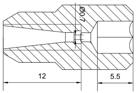
Figure 1.
Two-dimensional geometric model of the nozzle.
2.2. Governing Equation
2.2.1. Multiphase Flow Model
A cavitation jet belongs to gas–liquid two-phase flow, and the Euler or Lagrange model can be selected as needed to calculate its flow field. In the Euler model, the movement of each phase is described based on the Euler coordinate system, while in the Lagrange model, the movement of the discrete phase is recorded as a trajectory. To reduce the amount of calculation, the Euler model is typically used to calculate the gas–liquid two-phase flow when the individual motion characteristics of the discrete phase are not considered. This study used the mixture model to calculate the mixed-phase flow field; the model’s governing equation is expressed as follows:
where is the average mass velocity, is the density of the mixed-phase, and is expressed as follows:
where is the viscosity of the mixed-phase and is defined as follows:
where n is the number of phases, is the volume force, and represents the slip velocity of subphase k.
2.2.2. Cavitation Model
When the mixture model is used to calculate the cavitation multiphase flow, the gas phase volume fraction transport equation is expressed as follows:
where Re and Rc are the evaporation and condensation rates, respectively, and their values can be calculated by the cavitation model.
Currently, the commonly used cavitation model is mainly derived from the Rayleigh–Plesset equation. This study used the Zwart–Gerber–Belamri cavitation model, and the mass transfer in the model is expressed as follows:
While ,
While ,
where RB is the cavity radius, αnuc is the volume fraction of the gas core in the liquid, Fvap is the evaporation coefficient, and Fcond is the condensation coefficient. The default parameters of ANSYS FLUENT were set as RB = 10−6 m, αnuc = 5 × 10⁻⁴, Fvap = 50, and Fcond = 0.01. Considering the impact of turbulence on cavitation, the pressure threshold of cavitation occurrence can be expressed as follows:
where and represent the liquid density and liquid turbulent kinetic energy, respectively, and the recommended value in ANSYS FLUENT 0.39 was adopted for coefficient C.
2.2.3. Turbulence Model
This study used the hybrid Shear Stress Transport—Scale Adaptive Simulation (SST-SAS) turbulence model to consider the cavitation turbulence. The SAS term in the ω equation is defined as QSAS; it is the turbulence transport equation of turbulent frequency. The relevant expressions are as follows:
where ξ2 = 3.51, σϕ = 2/3, CSAS = 2.0, and L is the length scale of the model turbulence.
2.3. Meshing
Because a structured mesh has the advantages of good convergence, high accuracy, and fast calculation speed for jet flow simulation, ANSYS ICEM was used for the structured meshing of the jet flow field, and the mesh was appropriately refined for key parts of the model such as the nozzle throat and nozzle outlet. The grid independence was evaluated based on the maximum pressure on the impact surface of the target. To ensure that the grid error is less than 1% and minimize the calculation, the number of grids was between 3.5 million and 4.5 million. The mesh of the computational domain is shown in Figure 2. The image of the mesh shows the boundary layer grids in the nozzle.
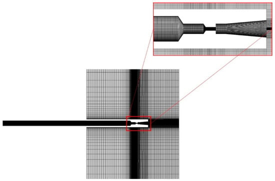
Figure 2.
Mesh of the computational domain.
2.4. Boundary Conditions
In the ANSYS FLUENT software, the computational boundary conditions were set according to the experimental situation, and the SIMPLE algorithm and finite volume method were used to discretize the equations. As the boundary conditions, the reference pressure in the calculation was set to 101,325 Pa, the nozzle inlet was set to pressure inlet with a gauge pressure value of 200 MPa, and the nozzle outlet was set to pressure outlet with a gauge pressure value of 0 MPa. The remaining boundaries were set to a no-slip wall surface.
3. Experimental Design
3.1. Specimen Preparation and Dynamic Strain Measurement
The sample material was Grade A marine steel, which has good corrosion and fatigue resistance. The main components of Grade A marine steel are listed in Table 1. Five groups of 200-MPa erosion samples with a size of 50 × 50 × 10 mm were fabricated. The samples were polished sequentially with #80–1200 sandpaper on the MP-2T metallographic sample grinding and polishing machine. The erosion test used the ultrahigh-pressure jet test platform of Jiangsu Marine Equipment Research Institute and Jiangsu Marine Technology Research Center (Figure 3). The jet medium was clean water, and the test was carried out at room temperature. The distance of the jet impacting the sample was 30 mm, and the impact angle was 60°.

Table 1.
Chemical composition of Grade A marine steel.
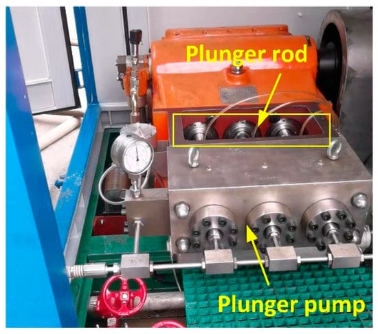
Figure 3.
Ultrahigh-pressure water jet test platform.
In the process of the water jet impacting the Grade A marine steel, the ASMC2-4 resistance strain gauges were used to collect the dynamic strain signal on the back of the specimen, and the simulation and experimental results were analyzed and compared. The BSF-3AA-T resistance strain gauges were attached to three different locations at the back of the specimen. The position distribution and wiring diagram are shown in Figure 4. Strain gauges at both ends were placed in this way only to get close to the middle strain gauge, which made the measurement more accurate. The specific parameters are as follows: resistance: 120 ± 0.5 Ω, sensitivity coefficient: 2.00–2.20, applicable temperature range: −30–80 °C. Strain gauge 2 was located behind the jet impact center point, and strain gauges 1 and 3 were in line with strain gauge 2. The signal sampling rate (samples/second) of each channel of the detection module was up to 12,800, the strain resolution (με) was 0.5 × 10⁻⁶, the strain measurement range (με) was up to ±1,920,000, and the strain measurement error was less than 0.02%.
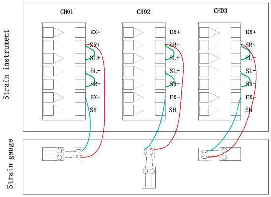
Figure 4.
Half-bridge one-to-one compensation strain measurement wiring diagram.
3.2. Microstructure and Surface Topography Detection
After the surface of the ultrahigh-pressure jet erosion specimen failed, the surface morphology and failure mechanism of the material after the impact of the Grade A marine steel were examined using an SEM, an XRD, an EDS, and other experimental equipment. Thus, the surface morphology and element distribution of the material after the impact of the Grade A marine steel were observed, and the surface morphology characteristics and failure mechanism of the material after erosion were analyzed. According to the dynamic strain and simulation of the water jet impacting the material, combined with the observation and analysis of the microscopic structure and surface morphology, the mechanism of the interaction between the ultrahigh-pressure water jet and the surface layer of Grade A marine steel and the erosion mechanism, were obtained.
4. Results and Discussion
4.1. Analysis of Flow Field Simulation
Shown in Figure 5 is the ultrahigh-pressure water jet impact on the target velocity field spatial distribution of the cloud; the internal and external flow field is divided into the nozzle inside the cavitation jet (I), free jet (II), and stagnation and high-speed diffusion (III). As can be more clearly seen from Figure 5, the jet gradually began to disperse from the nozzle after jet flow went into the external flow field, the central region of the velocity gradually decreased, and the turbulent region rapidly increased. This is due to the edge of the high-speed jet and air friction, resulting in a reduction in the continuity of the jet, the liquid column broken into liquid beads and mixed with air. This discrete liquid phase and gas phase also have a large speed/velocity and energy, mixed in the outer layer of the jet and imposing a large disturbance to the core region. As the distance of the jet increases, the liquid inside the jet is disturbed and gradually spreads to the turbulent region until the jet is completely atomized.
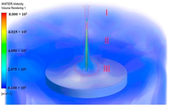
Figure 5.
Cloud map of the spatial distribution of velocity field of an ultrahigh pressure water jet impinging on the target.
The occurrence of cavitation in the nozzle is closely related to the nozzle’s geometric structure. According to Bernoulli’s equation, the flow velocity of a cross-section in the fluid is higher when the pressure in that section is relatively low. Figure 6a shows the nozzle cavitation effect cloud. The nozzle contraction section of the enormous pressure difference will produce a large number of cavities, and the ultrahigh-pressure water will gradually flow to the nozzle outlet. The cavitation phenomenon is a complex turbulent two-phase flow, and its numerical modeling involves a set of flow control equations, turbulence modeling, cavitation modeling, and many other aspects. Figure 6a shows that the location of the cavitation is where the jet field velocity sharply increases owing to the disappearance of cavities in the jet, which results in an implosion and leads to the higher velocity of the cavitating jet compared with the normal jet flow. Figure 6b shows the jet velocity cloud. As can be seen, at a certain jet distance within the core, the velocity of the jet was significantly higher, and the nozzle exit velocity reached 674 m/s.
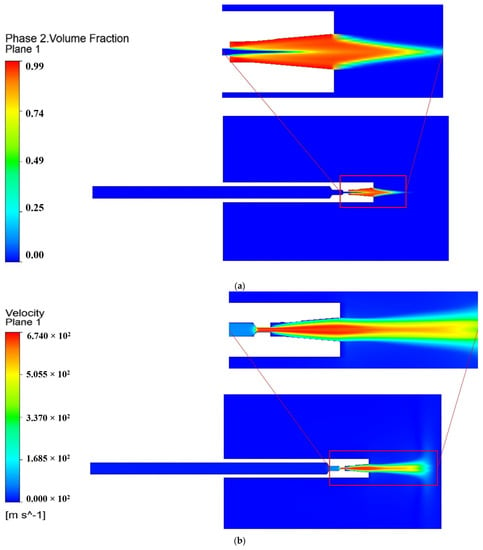
Figure 6.
Cavitation effect of nozzle and jet velocity clouds: (a) cavitation effect cloud; (b) jet velocity cloud.
4.1.1. Effect of Target Distance on Jet Effect
The erosion mechanism of the wall material during jet erosion consists of two main types: the first type is erosion through the vertical impact of the jet on the target wall surface, by which striking pressure is generated, and the surface substrate material is broken and removed; the second type is erosion through the radial velocity of the fluid near the wall surface, by which the wall surface produces radial shear stress resulting in the removal of material. The tensile strength of the rust layer is much lower than its compressive strength. Therefore, the destruction of the rust layer is more likely to be caused by the shear stress rather than percussion pressure. This study considered the maximum shear stress as the characteristic parameter for testing the hydrodynamic performance of the nozzle. Figure 7 shows the wall shear stress cloud. As can be seen, the wall shear stress first increased and then decreased along the radial distance. On the jet target surface, the shear stress (maximum principal stress) is an important measure of the ductile failure associated with plastic behavior, which conformed to the relation.
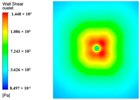
Figure 7.
Wall shear stress cloud.
The characteristic value of the Cauchy stress is called the principal stress; s1 is the maximum principal stress, and s2 is the minimum principal stress.
Numerical simulations were conducted using models with different target distances and constant internal nozzle parameters. Figure 8 shows the wall shear stress values along the radial distance at different target distances. As can be seen, as the target distance increased, the wall shear stress also increased, and the increasing trend gradually diminished. The target distance is the distance from the nozzle outlet to the wall; this section calculates the target distance of 30 mm, 50 mm, and 70 mm.
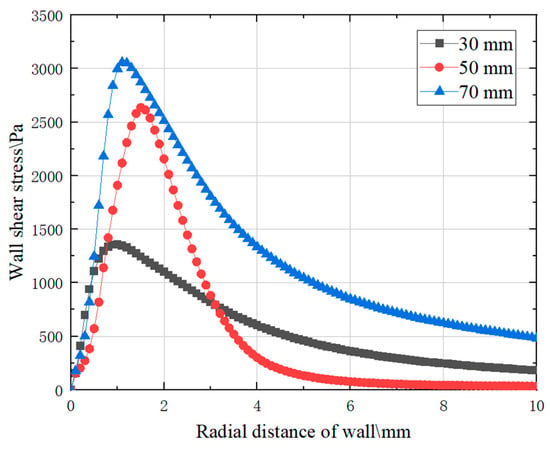
Figure 8.
Wall shear stress distributions under different standoff distances.
4.1.2. Influence of Incidence Angle on Effect of Jet
The impact of the incidence angle on the jet flow field is multifaceted. The jet velocity, water cushion thickness, shear stress, and pressure distribution on the wall on both sides of the central axis were affected by the incidence angle. When the jet was incident at a certain angle of inclination and collided with the target surface, impact flow occurred at the point of wall collision divergence. The oblique impact jet flow field velocity and wall shear stress cloud diagrams are shown in Figure 9. As can be seen, when the jet was tilted at the angle of 60 degrees, the peak wall shear stress increased. Therefore, by selecting an appropriate incidence angle, the energy loss of the jet can be reduced to a certain extent, which is important for improving the jet effect.
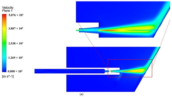
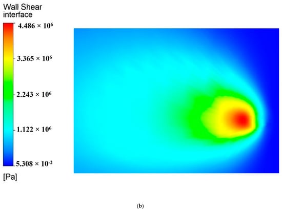
Figure 9.
Contour of oblique impinging jet velocity and wall shear stress: (a) jet velocity; (b) wall shear stress.
4.2. Dynamic Strain Measurement and Analysis
Under jet erosion by the ultrahigh pressure of 200 MPa, the dynamic strains at the three strain gauges tended to overlap, and the output graphs also overlapped. Moreover, the dynamic strain curves collected by the strain gauge at the three positions have similar variation rules. The dynamic strain curves collected by strain gauge 2 were analyzed as an example. Figure 10a,b show the strain curves and locally enlarged diagrams of the back of the sample, which was impacted by a water jet with a pressure of 200 MPa. The dynamic microstrain induced by jet impingement tended to be stable after approximately 24 ms, and the microstrain (με) ranged from 140 × 10−6 to 220 × 10−6. As shown in Figure 10a, the average dynamic microstrain at the back of the sample was approximately 180 × 10−6, and the strain amplitude was approximately 35 × 10−6–50 ×10−6.
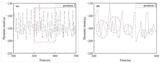
Figure 10.
Dynamic strain curve at the back of Grade A marine steel specimens: (a) dynamic strain obtained by strain gauge 2 under 200 MPa jet erosion; (b) local magnified view of dynamic strain obtained by strain gauge 2 under 200 MPa jet erosion.
Under the pressure of 200 MPa, the dynamic strain period at the back of the sample was approximately 20 ms, which is close to the pulsation frequency of the high-pressure water at the outlet of the high-pressure pump (44 Hz). Hence, it can be inferred that the dynamic strain signal of the water jet acting on the ship plate mainly depends on the response frequency of the high-pressure water outlet. The shock wave induced by the ultrahigh-pressure jet produced plastic deformation and was transmitted and reflected on the sample surface. The transmitted longitudinal wave caused the axial deformation of the sample and formed a longitudinal compression wave that propagated axially. The longitudinal compression wave reached the back of the specimen and was reflected and transmitted at the interface of the specimen. The reflected wave was the reverse tensile wave and continued to propagate into the specimen. The reverse tensile wave offloaded head-on with the next set of longitudinal compression waves, which led to fluctuations in the rear strain variables after the maximum peak value, as indicated by the circled positions in Figure 10b. According to the dynamic strain at the back of the Grade A marine steel sample, which was impacted by the water jet, and related impact dynamics theories, it can be deduced that the force acting on the sample surface was alternating stress with cyclic fluctuation.
4.3. Surface Morphology and Composition Analysis of Grade A Marine Steel Jet Erosion
4.3.1. Analysis of Phase and Microstructure
The XRD pattern of the Grade A marine steel was obtained, and the JADE software was used to search the XRD patterns of unrestricted elements for the main phase and limited elements for the secondary phase and single peak. By searching and matching the XRD patterns, the XRD phase analysis results for the Grade A marine steel were obtained as presented in Figure 11, and Fe3C was determined by searching the Card library of the JADE software, combined with a comprehensive analysis of marine steel material composition and TEM morphology image. Figure 11 shows that the ferrite phase corresponds to the main diffraction peak on the surface of the marine steel plate. The ferrite content in the Grade A marine steel is high, and its diffraction peak is strong. Cementite structures also exist in Grade A marine steel, and the cementite position, shape, and size greatly influence the steel properties.
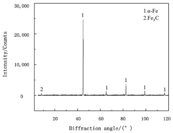
Figure 11.
XRD pattern of Grade A marine steel.
4.3.2. Analysis of Surface Morphology and Erosion Fracture
An optical microscope was used to observe the surface of the sample eroded by the water jet under the same impact pressure at different times. The observation results are as follows. Damage was not observed on the surface of sample 1 under the impact pressure of 200 MPa for 30 s. Under jet loading, some areas of sample 2 began to incur damage under impact for 40 s. In sample 3, the jet-loading region was completely destroyed, and the destruction was visible to the naked eye after impact for 50 s. Compared with sample 3, the failure area formed by the jet erosion of sample 4 under impact for 60 s did not significantly expand, but the failure depth significantly increased. In summary, under ultrahigh-pressure jet action, the surface of the sample began to incur damage after 40 s of jet loading. After 50 s, the surface was completely destroyed.
An SEM was used to observe the loading area of the ultrahigh-pressure jet on the surface of sample 2 (impact for 40 s) and sample 3 (impact for 50 s), as shown in Figure 12. In Figure 12a, numerous pits and cracks can be observed on the surface of sample 2. The pits have different sizes, approximately elliptic or circular shapes, and irregular distribution. The cracks are numerous, widely distributed, concentrated around the pits, and are regular quadrilateral or pentagonal. The original tiny bubbles expanded rapidly and formed cavitation bubbles, which underwent vaporization–collapse cycle. The collapse shock wave and cavitation microjet generated in the liquid flow acted on the surface of the material to form cavitation pits with an irregular distribution. Considering the dynamic strain curve in Figure 10 and the sample surface topography in Figure 12a, it can be inferred that, under the action of continuous cyclic alternating stress, fatigue cracks appeared in the cavitation pits under the repeated impact of stress waves, and the cracks expanded along the grain boundary direction. The average diameter and average area of the cavitation pits caused by the cavitation jet are 9.68–29.07 μm and 80.16–681.92 μm2, respectively. Cavitation pits existed in Figure 12b during impact time of 50 s. As the surface erosion of 50 s was more serious than that of 40 s, many cracks further expanded into pits under the joint action of cavitation jet and water wedge. The number of cracks decreased significantly, and the pits gradually expanded, but the cracks still existed. As shown in Figure 12b, there is no significant difference between the surface morphology of the central area and the peripheral area impacted by the 200 MPa ultrahigh-pressure water jet. Considering the simulation data, it is concluded that the dynamic pressure attenuation from the center to the edge of the 200 MPa ultrahigh-pressure water jet was small, and the pressure difference can be ignored.
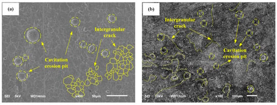
Figure 12.
SEM images of sample surface impacted by jet with the pressure of 200 MPa: (a) impact time of 40 s; (b) impact time of 50 s.
The loading area of the ultrahigh-pressure jet on the surface of sample 4 (impact for 60 s) was observed, and the typical failure morphology of the Grade A marine steel is shown in Figure 13. Under the cyclic stress of the ultrahigh-pressure water jet, the material surface broke down, and the soft phase or brittle phase precipitated along the grain boundary. Additionally, the soft phase structure broke, and cracks formed under the high impact pressure of the jet. Part of the cracks extended along the grain boundary. When the cracks extended to a certain degree, the material surface broke along the grain boundary, as shown in Figure 13a. Some cracks are accelerated to peel off under the action of water wedge, and the particles that had broken previously acted as an abrasive and squeezed into the crack surface, which accelerated the development of cracks along the depth and resulted in the spalling of the material surface and formation of spalling pits, as shown in Figure 13b. Moreover, when the microdefects on the surface of the material were subjected to cyclic shear stress, cracks also started appearing and gradually expanded. Owing to the low binding strength of the layered structure, the crack growth easily led to the separation of the layered structure and the formation of layer erosion, as shown in Figure 13c. The erosion zone is large, deep, and has steep gradient edges. The ultrahigh-pressure water jet caused microcracks and micropits on the material surface to minimize the large pressure difference. When the partial pressure of the jet was lower than a certain value, cavitation was produced because the jet gas gradually separated, and bubbles grew and eventually broke at high temperature and under high pressure, which produced shock waves and resulted in the wide-ranging microjet spread. Thus, pitting and needle-like cavitation holes were formed, as shown in Figure 13d.
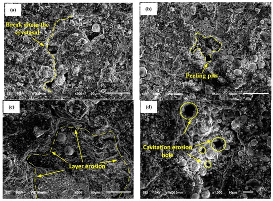
Figure 13.
SEM images of material surface fracture after erosion: (a) fracture along crystals; (b) peeling pits; (c) layer erosion; (d) cavitation erosion hole.
4.4. Jet Erosion and Stripping Model of Grade A marine Steel
From the dynamic strain analysis in Figure 10, it is understood that the impact force of the water jet caused alternating stress, which resulted in the fatigue failure of the Grade A marine steel sample. According to the simulation analysis and surface morphology observation by the SEM, the surface was damaged by the cavitation jet. Fatigue failure and cavitation jet erosion failure were caused by the alternating stress induced by the effluvium, and the surface of the Grade A marine steel samples exhibited different structural failure morphologies. Figure 14a–f show the schematic diagram of the water jet erosion and the stripping model of the Grade A marine steel under the pressure of 200 MPa. The surface model of the Grade A marine steel sample under water jet impact loading is shown in Figure 14a. In the process of the continuous loading of the water jet, a large number of cavitation bubbles formed owing to cavitation and contacted the material surface or an area near the surface. Because of the asymmetry of the upper and lower wall corner boundaries of the cavity, the cavity wall away from the surface breaks first, and then the cavity wall close to the surface breaks, thus forming a wall facing microjet and shock wave. Some soft phase tissues with low hardness are stripped by high-pressure microjet and shock waves to form cavitation pits, as shown in Figure 14b. The alternating stress generated by jet impingement caused fatigue on the sample surface. Under the pressure of 200 MPa, microcracks first formed from the cavitation pit, as shown in Figure 12a, and the cracks extended along the grain boundary, as shown in Figure 14c. Under the joint action of the cavitation jet and water wedge, the material surface cracks and cavitation pits continuously expanded and developed, as shown in Figure 14d. As the water jet impact time was extended, the ferrite with low hardness was the first to become damaged by fatigue during the crack expansion process in the jet impact area, and part of the hard phase structure with poor adhesion to the matrix was gradually stripped, which resulted in the formation of a spalling pit, as shown in Figure 14e. After the gradual stripping of structures with different hardness, erosion pits formed through each other on the surface of the material. After the effluents, only cementite and other hard phases and closely bonded structures remained, and the failure morphology shown in Figure 14f eventually formed.
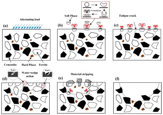
Figure 14.
Grade A ship steel jet erosion and peeling mode. (a) Alternating load (b) Stripped soft phase (c) Fatigue crack (d) Water wedge action (e) Stripped hard phase (f) failure morphology.
5. Conclusions
The following conclusions were drawn from this study:
- (1)
- According to the simulation results, the wall shear stress increased with the target distance, and the increasing trend gradually slowed down. When the jet was incident at a certain angle, the energy loss of the jet was reduced to a certain extent, and the peak value of shear stress on the wall increased, which played a significant role in improving the jet effect;
- (2)
- Under the pressure of 200 MPa, the average microstrain at the back of the center area of the Grade A marine steel was 180 × 10−6, and the microstrain amplitude was 35 × 10−6–50 × 10−6. The dynamic strain response frequency of the water jet on the ship plate was mainly determined by the pulsation frequency of the high-pressure water outlet, and the impact of the ultrahigh-pressure water jet on the material caused alternating stress with cyclic pulsation. At 200 MPa, the pressure at the center and edge of the jet was essentially unchanged, and the pressure difference could be ignored;
- (3)
- The matrix of Grade A marine steel consists of a ferrite and pearlite structure. Under the alternating stress action of the jet flow, fatigue and cavitation damage occurred on the material surface. After erosion, the long strip cementite hard phase was dominant in the core area of the Grade A marine steel, and the pearlite structure had not been washed. Moreover, after erosion under the pressure of 200 MPa, the typical fracture morphology characterized by spalling pits, layer erosion, and cavitation erosion holes was observed on the Grade A marine steel surface;
- (4)
- The jet erosion and stripping model of the Grade A marine steel were established, and the progressive peeling process of different hardness structures under the cyclic alternating stress action of the water jet, cavitation jet, and water wedge was described. The damage initiated from a fatigue crack and cavitation pit under the pressure of 200 MPa and the erosion mechanism of the water jet was elucidated.
Author Contributions
Writing—original draft, S.-M.C. and Y.-P.C.; Writing—review & editing, Y.-P.C., W.-D.S. and Y.-F.Y. Conceptualization, Y.-P.C.; methodology, Y.-P.C. and W.-D.S.; software, G.-W.W. and Y.-F.Y.; supervision, W.-D.S. All authors have read and agreed to the published version of the manuscript.
Funding
This work was supported by the National Natural Science Foundation of China (Nos. 51505236, 51979138), National High-Tech Ship Scientific Research Project of China (No. MC-202031-Z07), China Postdoctoral Science Foundation (No. 2019M651931), National Key Research and Development Project of China (No. 2019YFB2005300) and Postdoctoral Fund of Jiangsu (2021k606c).
Institutional Review Board Statement
Not applicable.
Informed Consent Statement
Not applicable.
Data Availability Statement
Data on the analysis and reporting results during the study can be obtained by contacting the authors.
Acknowledgments
The authors thank Nantong University and Nantong COSCO Shipyard Co., Ltd. for providing experimental equipment and all the people and institutions who helped the authors complete this paper.
Conflicts of Interest
The authors declare no conflict of interest.
References
- Hillegersberg, R.; Kort, W.; Kate, F.; Terpstra, O.T. Water-jet-cooled Nd:YAG laser coagulation: Selective destruction of rat liver metastases. Lasers Surg. Med. 2010, 11, 445–454. [Google Scholar] [CrossRef]
- Tang, S.; Yuan, S.; Zhu, Y. Convolutional Neural Network in Intelligent Fault Diagnosis Toward Rotatory Machinery. IEEE Access 2020, 8, 86510–86519. [Google Scholar] [CrossRef]
- Bai, L.; Zhou, L.; Jiang, X.; Pang, Q.; Ye, D. Vibration in a Multistage Centrifugal Pump under Varied Conditions. Shock. Vib. 2019, 2019, 1–9. [Google Scholar] [CrossRef]
- Alsoufi, M.S. State-of-the-Art in Abrasive Water Jet Cutting Technology and the Promise for Micro-and Nano-Machining. Int. J. Mech. Eng. Appl. 2017, 5, 1–14. [Google Scholar] [CrossRef] [Green Version]
- Peng, G.; Fan, F.; Zhou, L.; Huang, X.; Ma, J. Optimal Hydraulic Design to Minimize Erosive Wear in a Centrifugal Slurry Pump Impeller. Eng. Fail. Anal. 2020, 120, 105105. [Google Scholar] [CrossRef]
- Tabie, V.; Koranteng, M.; Yunus, A.; Kuuyine, F. Water-Jet Guided Laser Cutting Technology- an Overview. Lasers Manuf. Mater. Process. 2019, 6, 189–203. [Google Scholar] [CrossRef]
- Liu, H. Advanced Waterjet Technology for Machining Curved and Layered Structures. Curved Layer. Struct. 2019, 6, 41–56. [Google Scholar] [CrossRef]
- Cao, Y.P.; Zhu, P.F.; Shi, W.D.; Hua, G.R.; Wang, H.; Qiu, M. Correlation between X-Ray diffraction pattern and microstructure of surface of E690 high-strength steel induced by laser-shock processing. Vacuum 2022, 195, 110595. [Google Scholar] [CrossRef]
- Hwang, P.; Poon, Y.; Wu, J. Temperature Effects on Generation and Entrainment of Bubbles Induced by a Water Jet. J. Phys. Oceanogr. 1991, 21, 1602–1608. [Google Scholar] [CrossRef] [Green Version]
- Schumacher, B.; Charton, J.P.; Nordmann, T.; Vieth, M.; Enderle, M.; Neuhaus, H. Endoscopic submucosal dissection of early gastric neoplasia with a water jet-assisted knife: A Western, single-center experience. Gastrointest. Endosc. 2012, 75, 1166–1174. [Google Scholar] [CrossRef]
- Yang, Y.; Zhou, L.; Shi, W.; He, Z.; Han, Y.; Xiao, Y. Interstage difference of pressure pulsation in a three-stage electrical submersible pump. J. Pet. Sci. Eng. 2020, 196, 107–653. [Google Scholar] [CrossRef]
- Wang, C.; Wang, X.; Shi, W.; Weigang, L.; Keat, T.S.; Ling, Z. Experimental investigation on impingement of a submerged circular water jet at varying impinging angles and Reynolds numbers. Exp. Therm. Fluid Sci. 2017, 89, 189–198. [Google Scholar] [CrossRef]
- Peng, G.; Huang, X.; Zhou, L.; Zhou, G.; Zhou, H. Solid-liquid two-phase flow and wear analysis in a large-scale centrifugal slurry pump. Eng. Fail. Anal. 2020, 114, 104602. [Google Scholar] [CrossRef]
- Kumar, N.; Shukla, M. Finite element analysis of multi-particle impact on erosion in abrasive water jet machining of titanium alloy. J. Comput. Appl. Math. 2012, 236, 4600–4610. [Google Scholar] [CrossRef] [Green Version]
- Lasheras, J.; Villermaux, E.; Hopfinger, E. Break-up and atomization of a round water jet by a high-speed annular air jet. J. Fluid Mech. 1998, 357, 351–379. [Google Scholar] [CrossRef] [Green Version]
- Quaisie, J.K.; Yun, W.; Zhenying, X.; Chao, Y.; Li, F.; Baidoo, P.; Sekyi-Ansah, J.; Asamoah, E. Experimental Study on Water-Jet Shock Microforming Process Using Different Incident Pressures. Adv. Mater. Sci. Eng. 2020, 2020, 1–9. [Google Scholar] [CrossRef]
- Ribu, D.C.; Rajesh, R.; Thirumalaikumarasamy, D.; Ramachandran, C.S.; Ahamed Saleel, C.; Aabid, A.; Baig, M.; Saleh, B. Investigating the Water Jet Erosion Performance of HVOF-Sprayed WC-10Co Coatings on 35CrMo Steel Utilizing Design of Experiments. Coatings 2022, 12, 482. [Google Scholar] [CrossRef]
- Zhao, Y.L.; Liu, H.; Ji, Z.-L.; Li, X.L.; Yao, J. Experimental study on long-time erosion of 316 stainless steel in sand containing two-phase jet. J. Eng. Thermophys. 2018, 39, 361–365. [Google Scholar]
- Dong, X.; Duan, X. High pressure water jet shot peening technology. Surf. Technol. 2005, 34, 48–49. [Google Scholar] [CrossRef]
- Li, G.M.; Liang, Y.L.; Fan, H.J.; Zhang, X.F.; Zhu, Y. Effect of water jet shot peening pretreatment on contact fatigue properties of 42CrMo steel after nitriding. Mater. Guide 2019, 33, 3107–3112. [Google Scholar]
- Begic-Hajdarevic, D.; Cekic, A.; Mehmedovic, M.; Djelmic, A. Experimental Study on Surface Roughness in Abrasive Water Jet Cutting. Procedia Eng. 2015, 100, 394–399. [Google Scholar] [CrossRef] [Green Version]
- Tangwarodomnukun, V.; Wang, J.; Huang, C.Z.; Zhu, H.T. Heating and material removal process in hybrid laser-waterjet ablation of silicon substrates. Int. J. Mach. Tools Manuf. 2014, 79, 1–16. [Google Scholar] [CrossRef]
- Babu, M.; Muthukrishnan, N. Investigation on Surface Roughness in Abrasive Water-Jet Machining by the Response Surface Method. Mater. Manuf. Process. 2014, 29, 1422–1428. [Google Scholar] [CrossRef]
- Habak, M.; Lebrun, J.L. An experimental study of the effect of high-pressure water jet assisted turning (HPWJAT) on the surface integrity. Int. J. Mach. Tools Manuf. 2011, 51, 661–669. [Google Scholar] [CrossRef] [Green Version]
- Escobar-Palafox, G.A.; Gault, R.S.; Ridgway, K. Characterisation of Abrasive Water-jet Process for Pocket Milling in Inconel 718. Procedia CIRP 2012, 1, 404–408. [Google Scholar] [CrossRef] [Green Version]
- Melaibari, A.; Zhao, J.; Molian, P.; Bushlya, V.; Zhou, J.; Ståhl, J.-E.; Petrusha, I.; Shrotriya, P. Ultrahard boron nitride material through a hybrid laser/waterjet based surface treatment. Acta Mater. 2016, 102, 315–322. [Google Scholar] [CrossRef]
- Chillman, A.; Ramulu, M.; Hashish, M. Waterjet Water-Air Jet Surface Processing of a Titanium Alloy: A Parametric Evaluation. J. Manuf. Sci. Eng. 2016, 132, 165–174. [Google Scholar] [CrossRef]
- Karakurt, I.; Aydin, G.; Aydiner, K. An Experimental Study on the Depth of Cut of Granite in Abrasive Waterjet Cutting. Adv. Manuf. Process. 2012, 27, 538–544. [Google Scholar] [CrossRef]
- Shen, C.; Lin, B.; Wu, H. High pressure water jet slotting and influence on permeability of coal seams. J. China Coal Soc. 2011, 36, 2058–2063. [Google Scholar]
- Dehkhoda, S.; Hood, M. An experimental study of surface sub-surface damage in pulsed water-jet breakage of rocks. Int. J. Rock Mech. Min. Sci. 2013, 63, 138–147. [Google Scholar] [CrossRef]
Publisher’s Note: MDPI stays neutral with regard to jurisdictional claims in published maps and institutional affiliations. |
© 2022 by the authors. Licensee MDPI, Basel, Switzerland. This article is an open access article distributed under the terms and conditions of the Creative Commons Attribution (CC BY) license (https://creativecommons.org/licenses/by/4.0/).