
Research on Seepage of Jointed Rock Mass of Tunnel and Limited Discharge of Grouting

Abstract
:1. Introduction
- (1)
- Non-uniform permeability coefficient;
- (2)
- The permeability coefficient has obvious anisotropy;
- (3)
- Difficulty from the type definition of permeable medium;
- (4)
- Permeability and stress state interact significantly;
- (5)
- Permeability coefficient is difficult to determine;
- (6)
- There is a big difference between the generalized flow velocity and the actual flow velocity of the equivalent continuum model.
2. Establishment of Discrete Fracture Network
2.1. Seepage Characteristics of Fractured Rock Mass
- (1)
- One-dimensional problemFor the one-dimensional problem, it is assumed that the crack direction is parallel to the x-axis, the crack is smooth, the gap width is a, and the spacing between the cracks is b. The hydraulic gradient in the fracture is Jx, and the flow velocity is:the permeability coefficient is:
- (2)
- Two-dimensional problemFor the n group of fractures whose width is a and spacing is b, the maximum hydraulic gradient on the plane is set to J. The angle between the normal direction of fracture and x-axis is α, and the components are nx = cosα and ny = sinα, respectively. The hydraulic gradient components are Jx and Jy, and the equivalent continuous medium permeability tensor is:the general matrix form of writing is:
- (3)
- Three-dimensional problemFor the three-dimensional problem, there are n groups of cracks with fixed occurrences, the same crack spacing, and infinite extension. The general matrix form of the permeability tensor is:where the actual fracture, occurrence, spacing and other parameters are randomly distributed, and the size is not infinite extension, so the permeability tensor needs to be further determined according to the actual situation of fracture geometric parameters.
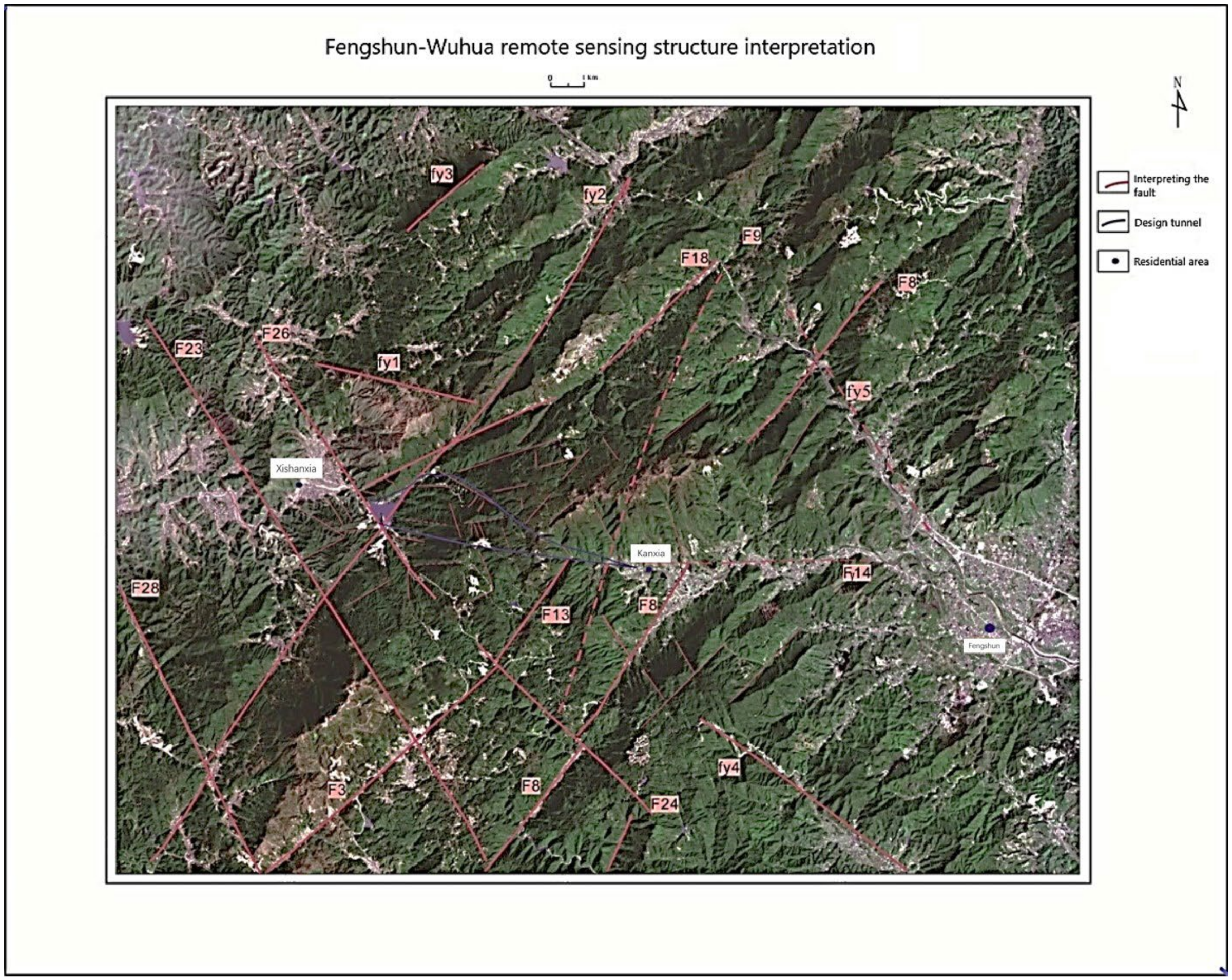
2.2. Engineering Hydrogeology of Hongtuzhang Tunnel Site
2.3. Establishment of Two-Dimensional Structural Plane Network
- (1)
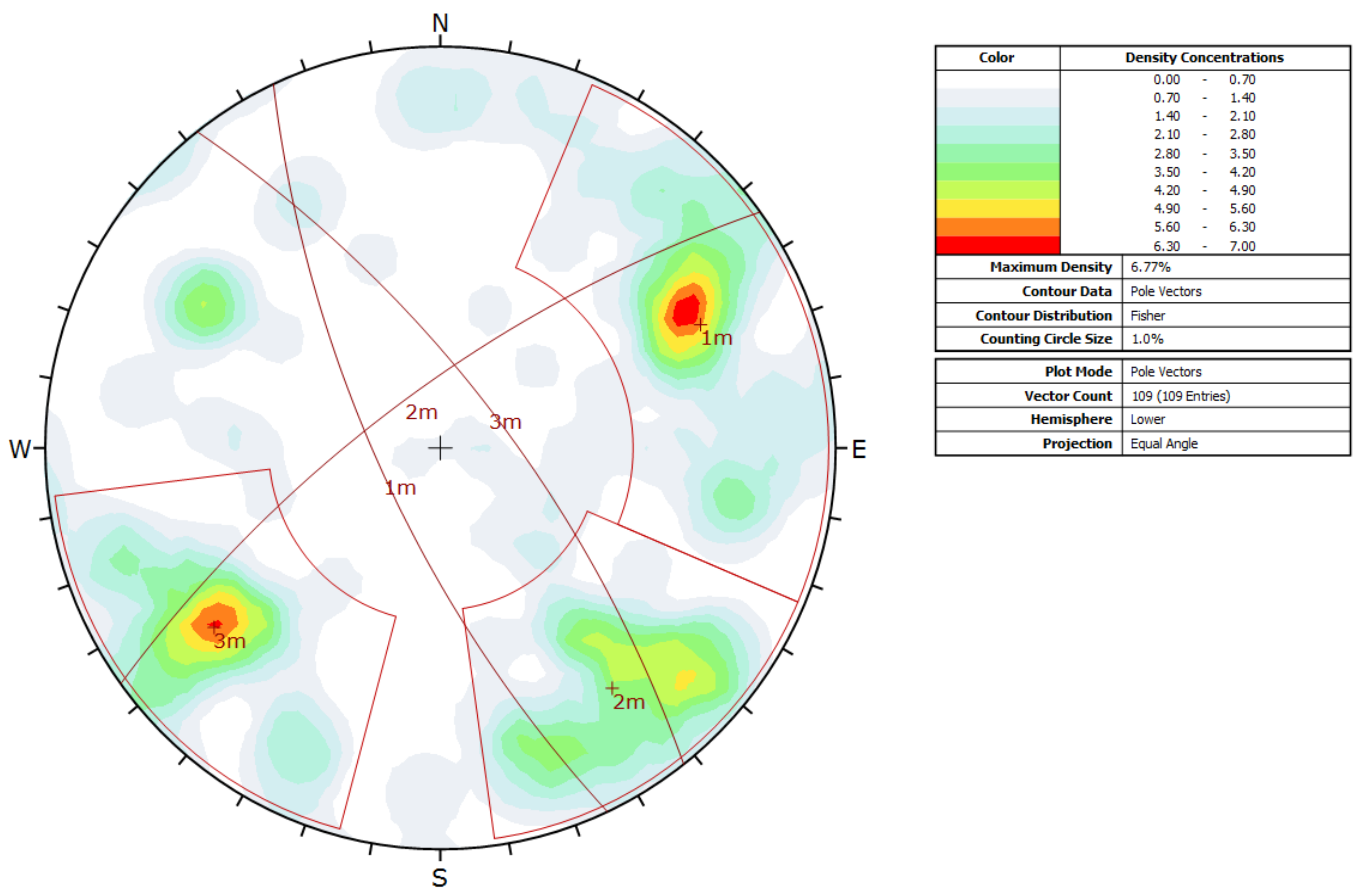
- Joint grouping
- 1.
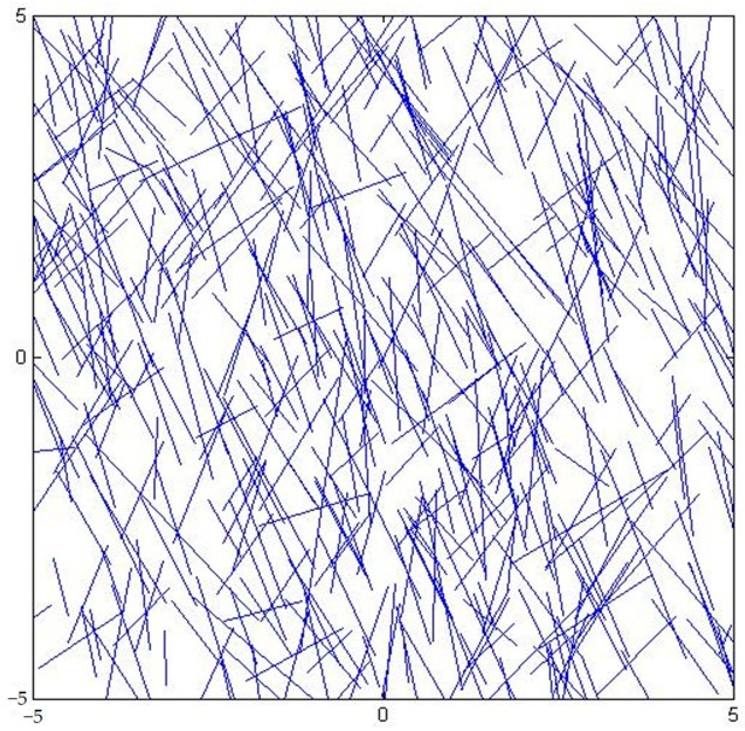
- In the designated generation domain, the two-dimensional structural surface traces are located at the same probability; that is, the structural surfaces are uniformly distributed within the generation domain.
- 2.
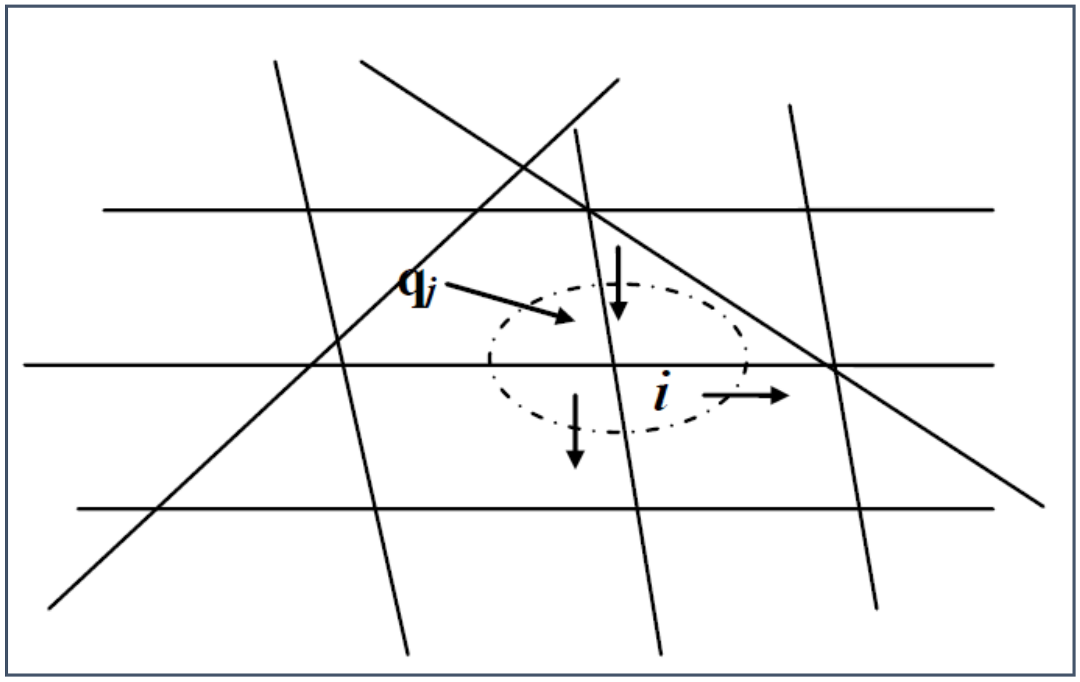
- In the two-dimensional random discontinuity network model, the structural surface trace is like the fracture trace length of the fractured rock mass, represented by a line segment. The angle between the counterclockwise direction of the x-axis and the trace is called the direction angle θ, which is the parameter for determining the occurrence distribution of the structural plane trace in the two-dimensional model. The direction angle is determined by the occurrence of the three-dimensional structural plane (inclination α and inclination angle β) and the azimuth angle γ of the section plane:
- (2)
- Dimension of structural plane
- (3)
- Estimation of structural plane density
- (4)
- Calculation of rock mass range
3. Calculation of Permeability Tensor
3.1. Mathematical Model of Seepage
- (1)
- The liquid flows unidirectionally in the fracture network;
- (2)
- The opening degree of the fissure remains unchanged at all times, and the rock mass does not deform;
- (3)
- The seepage–stress coupling effect is not considered.
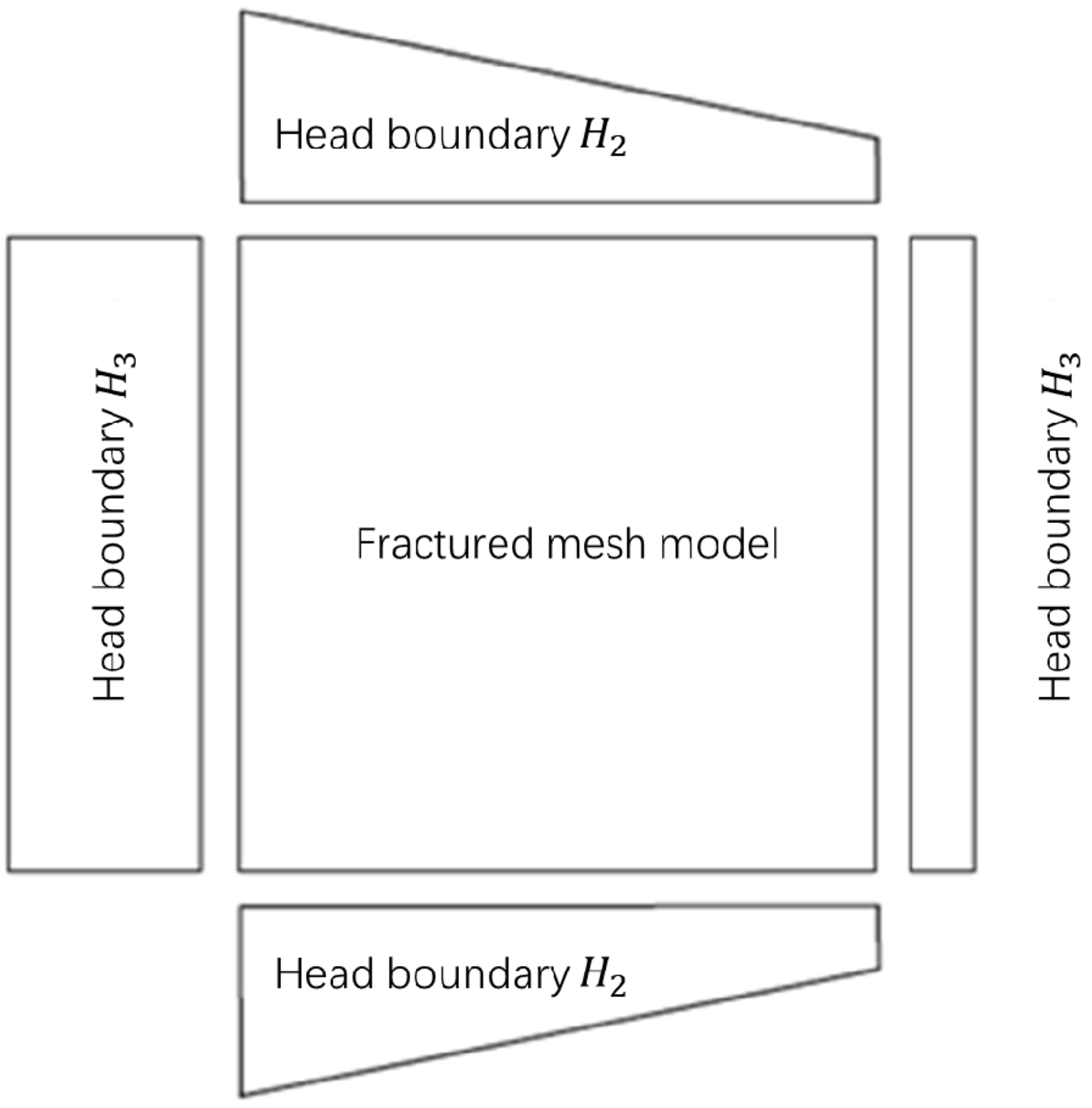
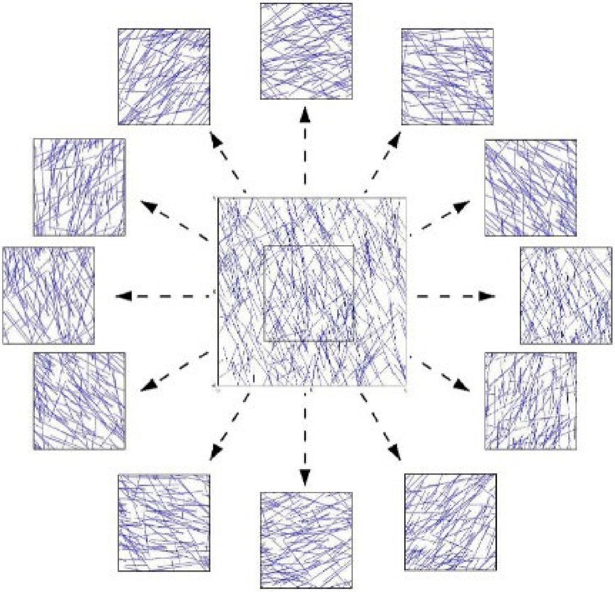
3.2. Calculation of Permeability Tensor
4. Tunnel Grouting Limited Discharge Design
4.1. Forecast of the Water Inflow of the Hongtuzhang Tunnel
- (1)
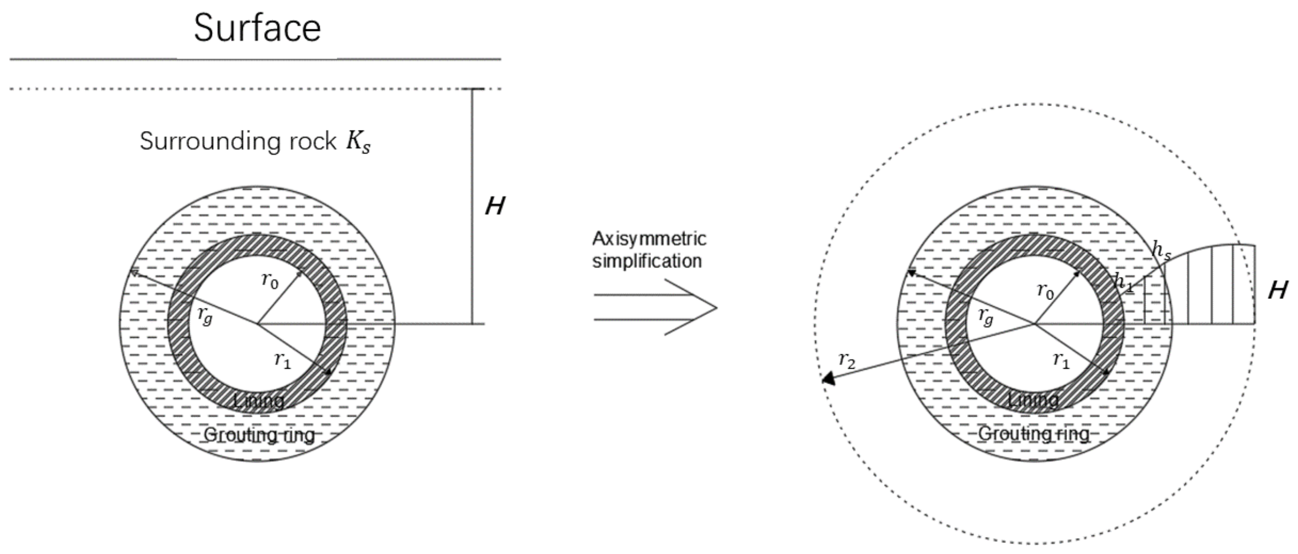
- After the excavation of the tunnel and before the construction of the lining structure, according to the Darcy law, there are:Considering the boundary conditions r = r1, h1 = 0, r = H and h1 = H, then the flow before the construction of the lining structure can be calculated as:Substituting the above equation into Darcy law, the water head of surrounding rock can be obtained:
- (2)
- After the lining support is implemented, the hydraulic potential field of the surrounding rock changes from h1 to h2, and within the lining range (r = r0 − r1), there is:According to the boundary conditions r = r0 and h2l = 0, we can get:Within the grouting range (r = r1 − rg), there are:According to the boundary conditions r = rg and h2g = h2g′, we can get:Within the range of surrounding rock (r = rg − H), there are:According to the boundary conditions r = H and h2m = H, we can get:At the junction of the grouting circle and the surrounding rock (r = rg), according to the continuity of the hydraulic potential, h2g = h2r, substituting Equation (31) into Equation (29), the hydraulic potential within the grouting circle can be obtained as:According to the continuity equation, when r = , the calculation results of Equations (27) and (32) should be the same. Thus, the flow rate after lining construction is obtained, and the external water pressure of the lining is:The axisymmetric problem can be used to simplify the deep-buried tunnel with a high water level.If grouting is not considered, the water inflow of the tunnel in Equation (33) can be expressed as:According to the geological survey report, the water level elevation of Huangmian Lake Reservoir is about 988 m, the design floor elevation of this section of the tunnel is about 304–316 m, and the height difference is 659–684 m, so H = 670 m. In the calculation, = 6 m and = 6.5 m, the lining is impermeable concrete, and the permeability coefficient = 1.74 × 10⁻⁹ m/s.
4.2. Optimal Design Calculation of Permeable Grouting Circle
- 1.
- After the hole is excavated.
- 2.
- Only considering lining, not grouting.
- 3.
- Carry out curtain grouting for the tunnel without considering the lining.
- 4.
- When curtain grouting and lining the tunnel.
- 5.
- Grouting and lining after draining and depressurizing the tunnel.
5. Conclusions
- (1)
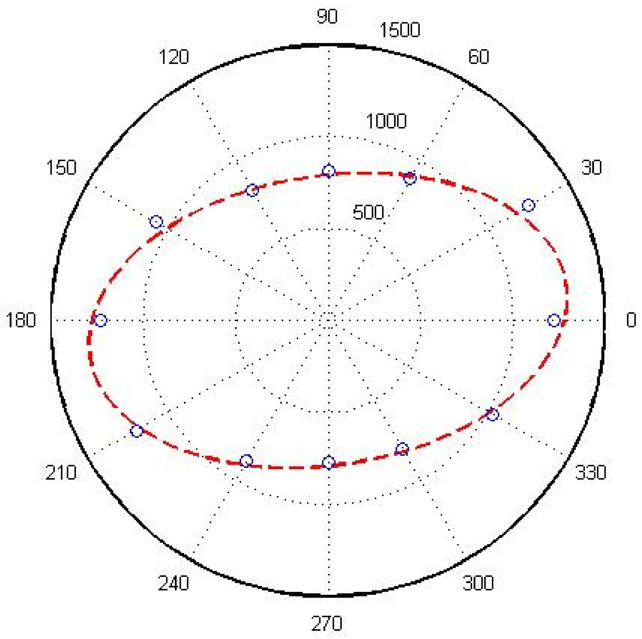
- The permeability of fractured rock mass has obvious anisotropy. Through statistical analysis of the structural plane information of fractured rock masses, the structural planes are grouped and statistically analyzed for the occurrence, trace length, density, and other parameters of the structural planes, and a two-dimensional discrete fracture network model of the rock mass is established, and the dimensional permeability tensor is calculated. The two main permeability coefficients were calculated as K1 = 1.61 × 10⁻⁶ m/s and K2 = 5.78 × 10⁻⁷ m/s, respectively. Considering the most unfavorable orientation, K1 = 1.61 × 10⁻⁶ m/s was selected for grouting design calculation. Before grouting the lining, the water inflow of the tunnel was 126.17 m3/(m∙d).
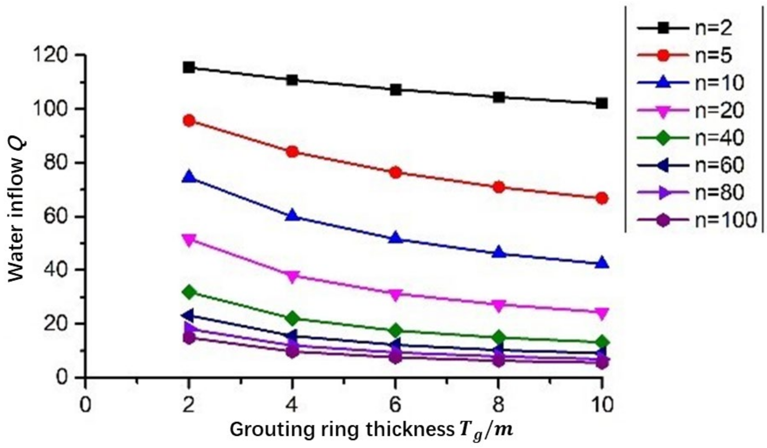
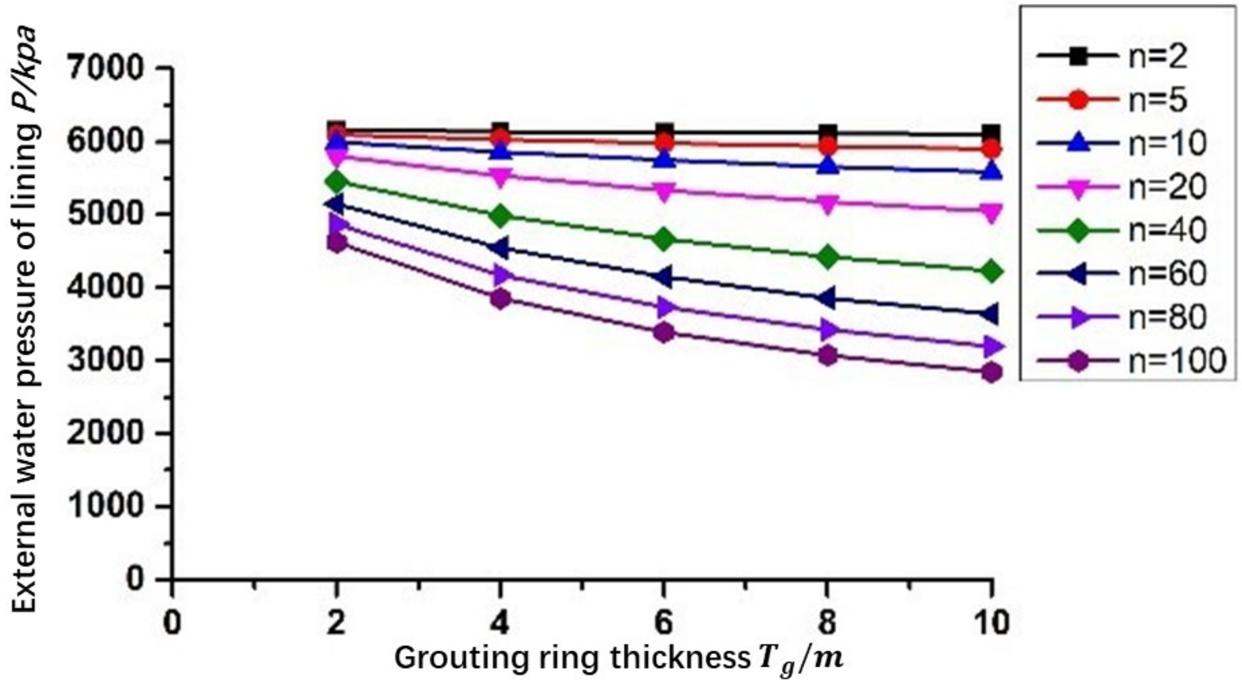
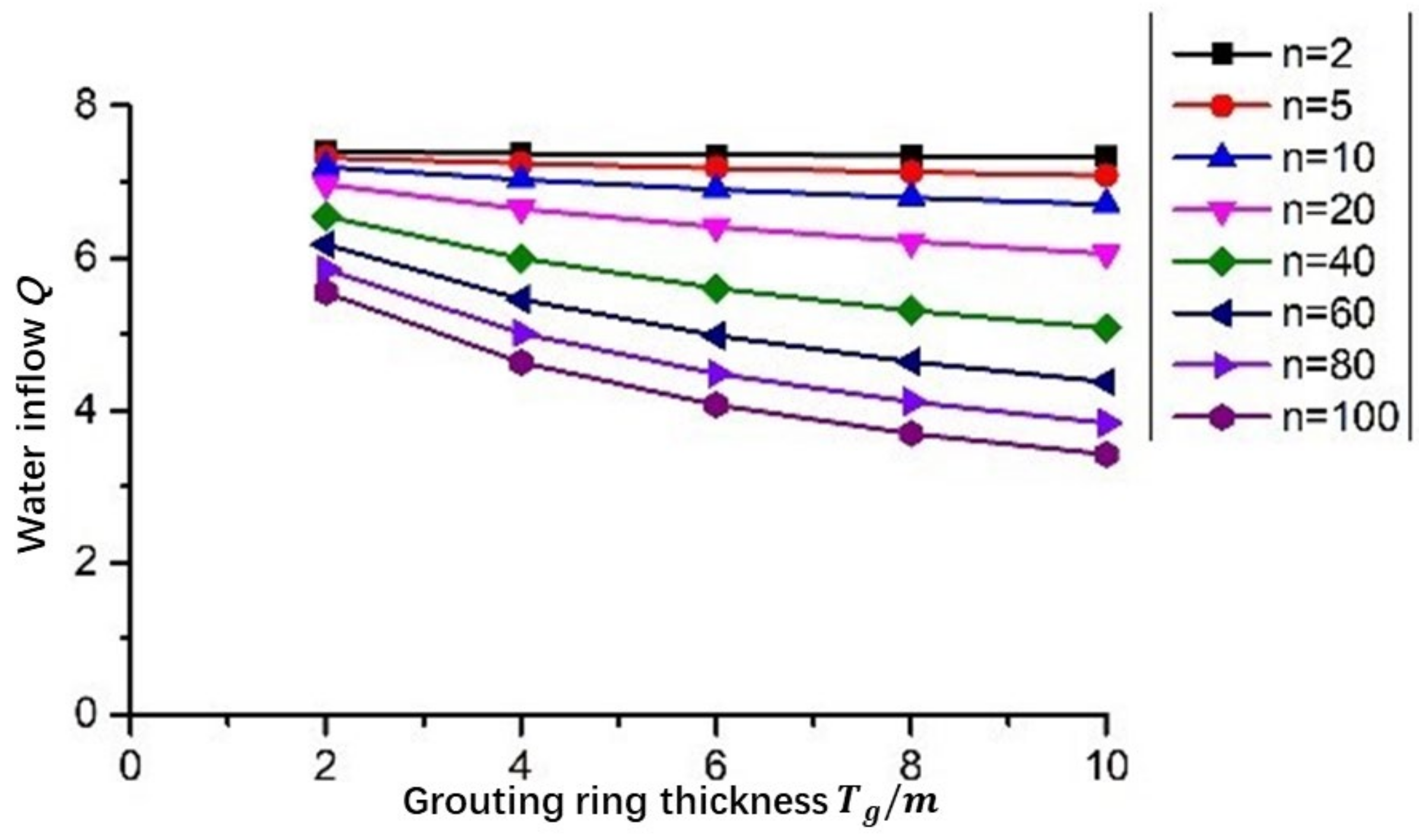
- (2)
- Grouting has a significant impact on the tunnel water inflow and the external water pressure of the lining. Grouting is an effective measure to deal with the tunnel water inrush. As the thickness of the grouting ring increases, the water inflow of the tunnel and the external water pressure of the lining decrease accordingly. With the same thickness of the grouting ring, the lower the permeability coefficient of the grouting ring, the smaller the water influx of the tunnel and the external water pressure of the lining.
- (3)
- According to the theoretical calculation of limited discharge, it is recommended that the tunnel should be grouted and lined after drainage. The recommended drainage volume of the tunnel is 3.0 m3/m∙d, the thickness of the grouting circle is Tg = 8m, and the permeability coefficient of the grouting circle kg = 1.61 × 10⁻⁸ m/s. Then, the water inflow of the tunnel is 0.69 m3/(m∙d), and the external water pressure of the tunnel lining is 0.58 MPa.
Author Contributions
Funding
Acknowledgments
Conflicts of Interest
References
- Ye, F.; Duan, J.-C.; Fu, W.-X.; Yuan, X.-Y. Permeability Properties of Jointed Rock with Periodic Partially Filled Fractures. Geofluids 2019, 2019, 4039024. [Google Scholar] [CrossRef]
- Tan, W.; Wang, P. Experimental Study on Seepage Properties of Jointed Rock-Like Samples Based on 3D Printing Techniques. Adv. Civ. Eng. 2020, 2020, 9403968. [Google Scholar] [CrossRef] [Green Version]
- Wang, P.T.; Yang, T.H.; Xu, T.; Yu, Q.L.; Liu, H.L. A Model of Anisotropic Property of Seepage and Stress for Jointed Rock Mass. J. Appl. Math. 2013, 2013, 420536. [Google Scholar] [CrossRef]
- Tsang, Y.W.; Tsang, C.F. Channel model of flow through fractured media. Water Resour. Res. 1987, 23, 467–479. [Google Scholar] [CrossRef] [Green Version]
- Boussinesq, M.; Gardon, J. Relationships between the prevalence and intensity of Loa loa infection in the Central province of Cameroon. Ann. Trop. Med. Parasitol 2001, 95, 495–507. [Google Scholar] [CrossRef] [PubMed]
- Louis, C. Rock hydraulics. In Rock Mechanics; Springer: Vienna, Austria, 1972; pp. 299–387. [Google Scholar]
- Snow, D.T. Rock fracture spacings, openings, and porosities. J. Soil Mech. Found. Div. 1968, 94, 73–91. [Google Scholar] [CrossRef]
- Jones, F.O., Jr. A laboratory study of the effects of confining pressure on fracture flow and storage capacity in carbonate rocks. J. Pet. Technol. 1975, 27, 21–27. [Google Scholar] [CrossRef]
- Kranzz, R.L.; Frankel, A.D.; Engelder, T.; Scholz, C.H. The permeability of whole and jointed Barre granite. Int. J. Rock Mech. Min. Sci. Geomech. Abstr. 1979, 16, 225–234. [Google Scholar] [CrossRef]
- Gale, J.E. The effects of fracture type (induced versus natural) on the stress-fracture closure-fracture permeability relationships. In Proceedings of the 23rd US Symposium on Rock Mechanics (USRMS), Berkeley, CA, USA, 25–27 August 1982. [Google Scholar]
- Zhang, X.; Sanderson, D.J. Numerical study of critical behaviour of deformation and permeability of fractured rock masses. Mar. Pet. Geol. 1998, 15, 535–548. [Google Scholar] [CrossRef]
- Sun, J.; Zhao, Z. Effects of anisotropic permeability of fractured rock masses on underground oil storage caverns. Tunn. Undergr. Space Technol. 2010, 25, 629–637. [Google Scholar] [CrossRef]
- Baghbanan, A.; Jing, L. Stress effects on permeability in a fractured rock mass with correlated fracture length and aperture. Int. J. Rock Mech. Min. Sci. 2008, 45, 1320–1334. [Google Scholar] [CrossRef]
- Wu, Y.-Q. Research on the relationship between stress and seepage in fractured rock mass. Hydrogeol. Eng. Geol. 1995, 6, 30–35. [Google Scholar]
- Liu, J. Two-Dimensional Nonlinear Seepage Characteristics and Model of Rock Mass Fracture Network. Ph.D. Thesis, Shandong University, Jinan, China, 2019. [Google Scholar]
- Wang, Z.-J.; Li, Z.; Lu, L. Research on the distribution of permeability coefficient of surrounding rock based on seepage force. Chin. J. Undergr. Space Eng. 2018, 14, 131–136. [Google Scholar]
- Li, X.-Q. Tunnel Engineering Technology; China Building Industry Press: Beijing, China, 2011. [Google Scholar]
- Snow, D. The frequency and apertures of fractures in rock. Int. J. Rock Mech. Min. Sci. Géoméch. Abstr. 1970, 7, 23–40. [Google Scholar] [CrossRef]
- Cacas, M.C.; Ledoux, E.; de Marsily, G.; Tillie, B.; Barbreau, A.; Durand, E.; Feuga, B.; Peaudecerf, P. Modeling fracture flow with a stochastic discrete fracture network: Calibration and validation: 1. The flow model. Water Resour. Res. 1990, 26, 479–489. [Google Scholar] [CrossRef]
- Robertson, A.M. Interpretation of Geological Factors for Use in Slope Theory. 1970, pp. 55–71. Available online: https://xueshu.baidu.com/usercenter/paper/show?paperid=a2184df5579e38086d413c9e34c879e6 (accessed on 14 November 2021).
- Kulatilake, P.H.S.W.; Wu, T.H. Estimation of mean trace length of discontinuities. Rock Mech. Rock Eng. 1984, 17, 215–232. [Google Scholar] [CrossRef]
- Zhang, G.-K.; Xu, W.-Y. Fracture network simulation and REV scale research. Rock Soil Mech. 2008, 29, 1675–1680. [Google Scholar]


| Total Number of Structural Planes | Group Number of Structural Plane | Number of Structural Planes | The Mean Orientation | |
|---|---|---|---|---|
| Dip Direction α (°) | Dip Angle β (°) | |||
| 78 | 1 | 29 | 245.48 | 73.14 |
| 2 | 26 | 324.19 | 73.04 | |
| 3 | 23 | 52.09 | 72.87 | |
| Group Number of Structural Plane | Dip Direction α (°) | Dip Angle β (°) | Direction Angle θ (°) |
|---|---|---|---|
| 1 | 245.48 | 73.14 | 115.70 |
| 2 | 324.19 | 73.04 | 111.59 |
| 3 | 52.09 | 72.87 | 57.81 |
| Group Number of Structural Plane | Mean Value (m) | Standard Deviation (m) | Probability Distribution Type |
|---|---|---|---|
| 1 | 1.59 | 0.74 | Normal distribution |
| 2 | 1.8 | 0.88 | Gamma distribution |
| 3 | 1.67 | 0.68 | Normal distribution |
| Group Number of Structural Plane | E(λν) (Strip/m3) | E(D) (m) | E(λa) (Strip/m2) |
|---|---|---|---|
| 1 | 2.9243 | 1.5931 | 1.5529 |
| 2 | 2.5047 | 1.7981 | 1.5012 |
| 3 | 2.7163 | 1.6717 | 1.5136 |
| Angle (°) | Permeability Coefficient (m/s) | Radius of Penetration Ellipse () |
|---|---|---|
| 0 | 6.72 × 10⁻⁷ | 1.22 × 10³ |
| 30 | 6.38 × 10⁻⁷ | 1.25 × 10³ |
| 60 | 1.26 × 10⁻⁶ | 8.91 × 10² |
| 90 | 1.52 × 10⁻⁶ | 8.11 × 10² |
| 120 | 1.52 × 10⁻⁶ | 8.12 × 10² |
| 150 | 8.72 × 10⁻⁷ | 1.07 × 10³ |
| 180 | 6.65 × 10⁻⁷ | 1.23 × 10³ |
| 210 | 7.02 × 10⁻⁷ | 1.19 × 10³ |
| 240 | 1.29 × 10⁻⁶ | 8.80 × 10² |
| 270 | 1.67 × 10⁻⁶ | 7.74 × 10² |
| 300 | 1.55 × 10⁻⁶ | 8.04 × 10² |
| 330 | 9.44 × 10⁻⁷ | 1.03 × 10³ |
Publisher’s Note: MDPI stays neutral with regard to jurisdictional claims in published maps and institutional affiliations. |
© 2022 by the authors. Licensee MDPI, Basel, Switzerland. This article is an open access article distributed under the terms and conditions of the Creative Commons Attribution (CC BY) license (https://creativecommons.org/licenses/by/4.0/).
Share and Cite
Zheng, L.; Lian, X.; Huang, D.; Li, X.; Zou, J. Research on Seepage of Jointed Rock Mass of Tunnel and Limited Discharge of Grouting. Water 2022, 14, 104. https://doi.org/10.3390/w14010104
Zheng L, Lian X, Huang D, Li X, Zou J. Research on Seepage of Jointed Rock Mass of Tunnel and Limited Discharge of Grouting. Water. 2022; 14(1):104. https://doi.org/10.3390/w14010104
Chicago/Turabian StyleZheng, Lifei, Xingwei Lian, Dan Huang, Xiaoqing Li, and Jinzhou Zou. 2022. "Research on Seepage of Jointed Rock Mass of Tunnel and Limited Discharge of Grouting" Water 14, no. 1: 104. https://doi.org/10.3390/w14010104
APA StyleZheng, L., Lian, X., Huang, D., Li, X., & Zou, J. (2022). Research on Seepage of Jointed Rock Mass of Tunnel and Limited Discharge of Grouting. Water, 14(1), 104. https://doi.org/10.3390/w14010104