Article

Comparison of Desalination Technologies Using Renewable Energy Sources with Life Cycle, PESTLE, and Multi-Criteria Decision Analyses

1
Environmental and Process Engineering Research Group, Department of Chemical and Environmental Process Engineering, Budapest University of Technology and Economics, Műegyetem rkp. 3, H-1111 Budapest, Hungary
2
SuPER (Sustainable Process Engineering Research) Team, Polytechnic University of Milan, Piazza Leonardo da Vinci 32, 20133 Milan, Italy
*
Author to whom correspondence should be addressed.
Water 2021, 13(21), 3023; https://doi.org/10.3390/w13213023
Submission received: 17 September 2021 / Revised: 10 October 2021 / Accepted: 19 October 2021 / Published: 28 October 2021

Abstract

:
Nowadays, desalination continues to expand globally, which is one of the most effective solutions to solve the problem of the global drinking water shortage. However, desalination is not a fail-safe process and has many environmental and human health consequences. This paper investigated the desalination procedure of seawater with different technologies, namely, multi-stage flash distillation (MSF), multi-effect distillation (MED), and reverse osmosis (RO), and with various energy sources (fossil energy, solar energy, wind energy, nuclear energy). The aim was to examine the different desalination technologies’ effectiveness with energy sources using three assessment methods, which were examined separately. The life cycle assessment (LCA), PESTLE, and multi-criteria decision analysis (MCDA) methods were used to evaluate each procedure. LCA was based on the following impact analysis and evaluation methods: ReCiPe 2016, IMPACT 2002+, and IPCC 2013 GWP 100a; PESTLE risk analysis evaluated the long-lasting impact on processes and technologies with political, economic, social, technological, legal, and environmental factors. Additionally, MCDA was based on the Technique for Order Preference by Similarity to the Ideal Solution (TOPSIS) method to evaluate desalination technologies. This study considered the operational phase of a plant, which includes the necessary energy and chemical needs, which is called “gate-to-gate” analysis. Saudi Arabia data were used for the analysis, with the base unit of 1 m3 of the water product. As the result of this study, RO combined with renewable energy provided outstanding benefits in terms of human health, ecosystem quality, and resources, as well as the climate change and emissions of GHGs categories.

1. Introduction

1.1. Overview of Desalination in the World

About 71% of the Earth’s surface is covered with water, but only a small part of it can be considered as drinkable water, i.e., 2.5% of the Earth’s water. Overall, just under 0.7% of water resources are available to people [1]. From this amount, we have to satisfy the ever-increasing water consumption of 7.8 billion people currently living (150–400 L/person a day [2]). In addition to the increasing water consumption, the human population is also anticipated to increase. It is predicted that only 60% of the demanded water will be available for consumption in 2030 [3]. The Economic Cooperation and Development (OECD) has predicted that about 40% of the population will live in water-stressed regions by 2050 [4]. It is hard to imagine that more than half of the humans on Earth will not have access to clean, drinkable water. This number may continue to drop in the coming decades as we are increasingly exposed to our water sources. In areas where there are not enough available freshwater sources, another solution has to be found. Among other things, the process of desalination of seawater has been proved to be an effective alternative.
The desalination technology was first introduced on a larger scale in the Middle East during World War II, due to the general lack of water, and is becoming more widespread as the population increases and the drinking water stock is reduced [5,6]. Around the world, the number of desalination plants has increased with an average rate of about 6.8% a year since 2010, with the average annual capacity addition being about 4.6 million m3/day. By February 2020, there were 20,971 desalination projects with 16,876 installed plants, with the capacity of 97.2 million m3/day of freshwater production [7]. Nowadays, over 150 countries have already used desalination technologies to provide clean water for about 300 million people [8].
The desalination capacity in Saudi Arabia, the United Arab Emirates (UAE), Kuwait, and Qatar accounts for 55% of the total global share. Desalination plants for urban water are located throughout the world but are especially predominant in the Middle East and North Africa. As shown in Figure 1, the Middle East and North Africa had the largest regional desalination market in 2019, with around 45.32% of the total capacity, followed by East Asia and the Pacific (17.52%), North America (11.34%), and Western Europe (8.75%). The lowest regional desalination capacities were found for Southern Asia (2.94%), Eastern Europe and Central Asia (2.26%), and sub-Saharan Africa (1.78%), where desalination is mainly limited to small facilities for private and industrial applications [9]. Al-Jubail in Saudi Arabia is the largest desalination plant in the world, with a capacity of 1.4 million m3/day of water [10]. Desalination plants globally focused along the coast also tend to be larger than desalination plants on the mainland. The highest desalination capacity is where oil availability is the highest (most desalination plants use fossil fuels), such as the US and North Africa.

1.2. Desalination Technology

Desalination technology provides drinking water for people in places where drinking water would otherwise be an issue. The water produced can also be used for irrigation, such as in drought and dry areas, which can reduce the import dependency of a given area, contribute to the local economy, and provide food supply improvements [11,12]. The desalination process has been using proven and working technologies for decades, providing a reliable process. However, it is not a consequence-free procedure; one of these drawbacks is discharged flow from desalination plants. Environmental impacts (EIs) of the desalination process are assessed based on the utilized feedwater sources, the desalination technology, and the management of the waste brine and heat generated [13,14]. The various EIs are brine discharge, GHG emissions, toxic chemical emissions, water intake activities, and high energy consumption. Indeed, brine discharge and high energy consumption are the main and most significant impacts. The concentration of brine solutions is 1.6–2 times greater than the salinity of seawater (35 g/L), and their amount is also huge [15,16,17]. The temperature of brine produced by thermal-based technologies is also 1.37–1.82 times warmer than the average seawater temperature (22 °C) [18,19,20]. High temperature levels and salinity discharge affect marine organisms and cause biological problems [21,22,23,24]. Moreover, the used chemicals in the desalination process can also be returned to the sea. These are largely chlorine, antiscalants (polymeric substances such as polyphosphates, phosphonates, and polycarbonic acids), coagulants (ferric chloride (FeCl3), ferric sulfate [Fe2(SO4)3], aluminium chloride, and polyelectrolytes), flocculants (cationic polymer), strong acid/base sulfuric acid (H2SO4) and hydrochloric acid (HCl), oxidizing agents (sodium hypochlorite (NaOCl) and calcium hypochlorite [Ca(ClO)2]), reducing agents (bisulfite (HSO3), foaming inhibitors, and heavy metals (Cu, Fe, Ni, Mo, Cr, Cd, Pb, Hg, U, As) that are released into the water [17,25,26,27]. The substances thus introduced can cause a change in the pH of the water and an increase in the nutrient content and algae, which can lead to an overheating of the oxygen balance [28]. Drainage pipelines for desalination can suck up small aquatic organisms, damaging the local ecosystem. This can be reduced by installing a grid. Huge flue gas emissions and greenhouse gases from desalination plants contribute to air pollution in the environment. Annual global emissions from desalination plants are predicted to be increased by 0.4 billion tons of CO2 equivalent by 2050 [29]. Desalination needs a high energy demand, which has significant costs. Desalination technology requires an 8–20 times greater energy intensity than conventional surface water treatment technology (see Table 1) [30].
Desalination is essentially a process in which freshwater is separated from brackish water or saltwater. To run this process, there are two types of required energy (thermal, electricity). Desalination technology includes two major categories: thermal technology (traditional technology) and membrane technology (modern technology). The properties of thermal and membrane techniques are summarized in Table 2.

1.2.1. Thermal Desalination Technology

The thermal process is a phase-changed method in which the feedwater is heated under an operating temperature and pressure. Water vapor condenses as pure water, leaving behind salts and other non-volatile substances. Thermal processes are operated using heat and mechanical energy with a larger required amount compared to membrane processes. Therefore, most of the operational processes with many steps reuse heat through a sequential process of condensation and evaporation [33]. The thermal technologies include multi-effect distillation (MED), mechanical vapor compression (MVC), multi-stage flash distillation (MSF), and thermal vapor compression (TVC).
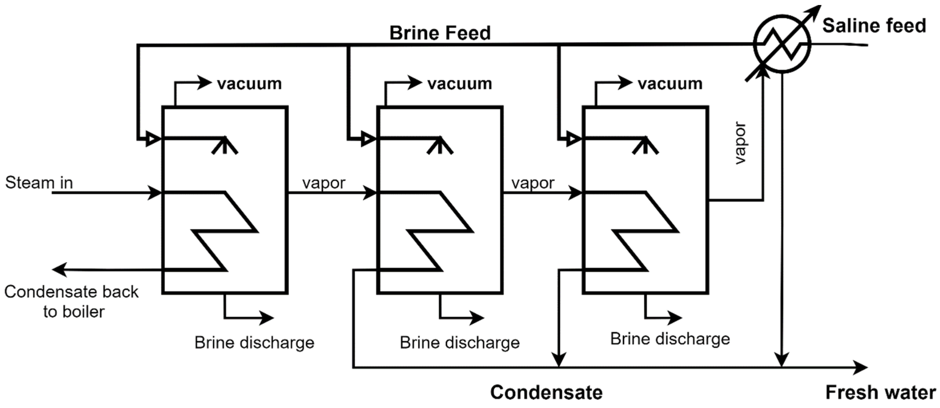
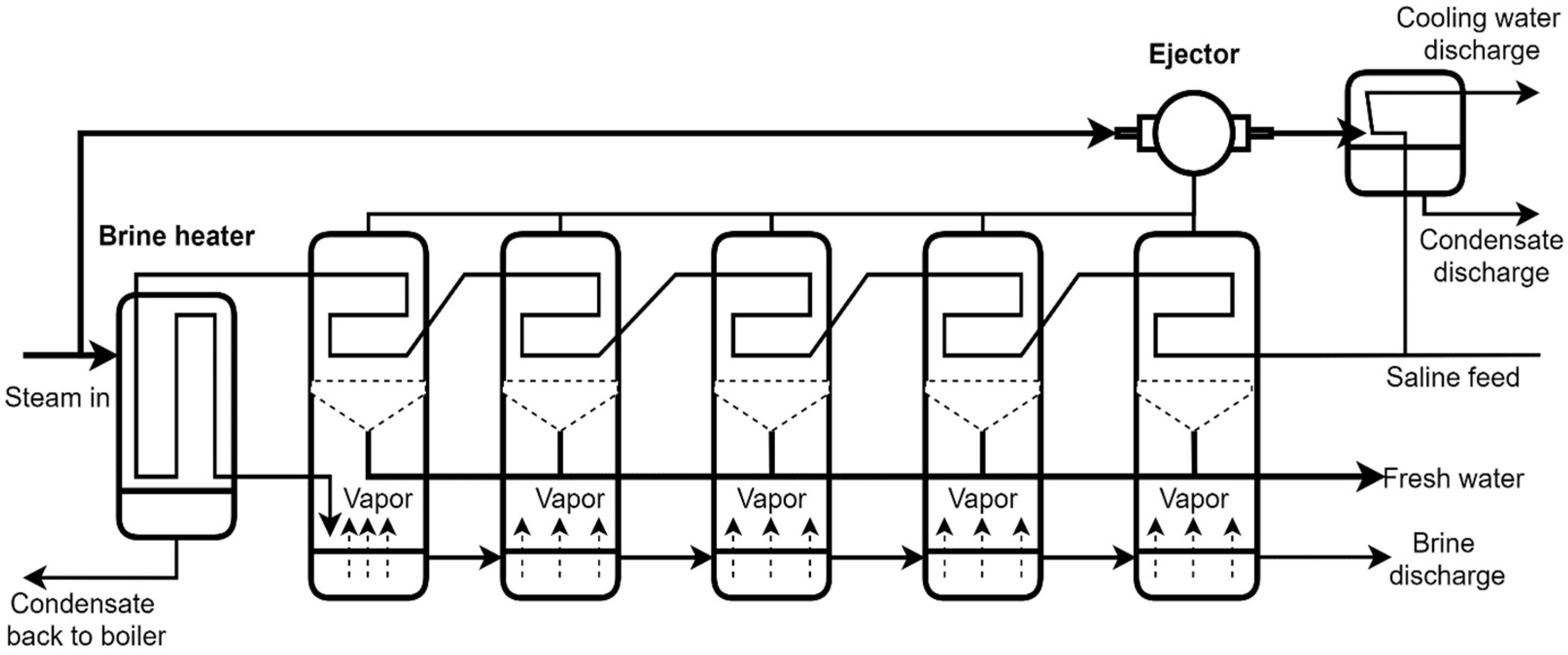
The theoretical operation of the MED and MSF techniques is shown in Figure 2 and Figure 3. In MED, the vapors of each stage condense in the next successive stage; the hot pipes are then sprayed with seawater to evaporate the water; this process is repeated for the next stage. A saline solution is collected at the bottom of each stage and circulated to the next stage or delivered out of the system [34]. MED units can be arranged in several ways, depending on the type of heat exchangers (horizontal or vertical), the direction of flow of the brine or steam (forward, backward, parallel), etc. For energy efficiency, steam is usually extracted from a power plant’s steam turbine or utilized as waste energy from other industrial processes. As the primary steam does not come into direct contact with the brine, the condensate inside the evaporator is usually circulated, and the boiler chemicals are not spread into the pure distillate. MSF is based on heat transfer desalination technology consisting of the evaporation and condensation of water. It is an energy-intensive process that requires both heat and electricity. The evaporation and condensation steps are connected in several stages so that the latent heat of evaporation is recovered by preheating the incoming water. The principle of the process is that the saltwater is evaporated, and the water and salt can be separated. Evaporation occurs several times (15–20 times) in series-connected chambers and at low pressure so that the water boils at a lower temperature [35].
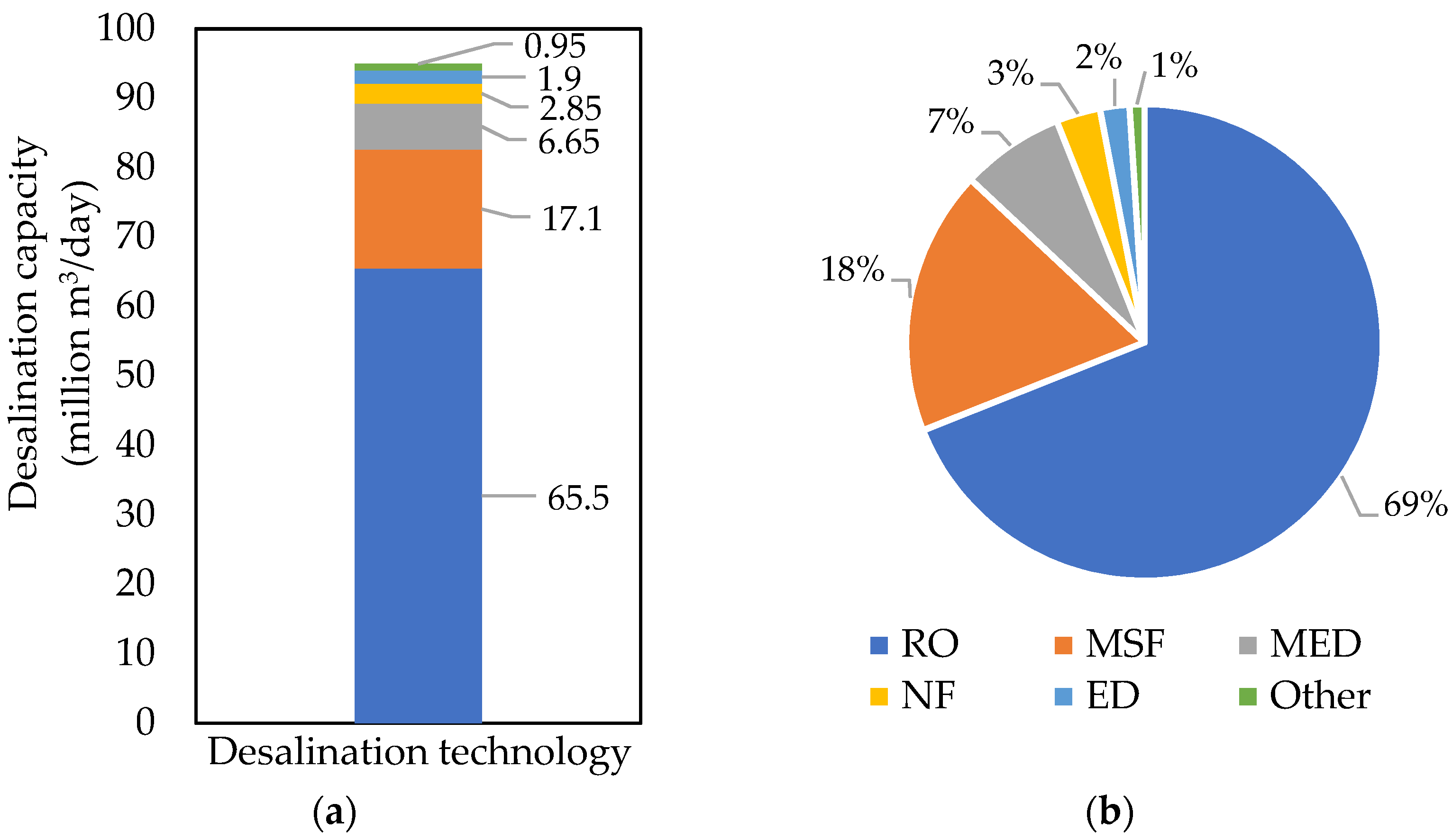
Figure 4 shows the current contribution of installed desalination technologies all over the world. The most commercially used thermal technology is MSF, with 18% of the market share of commercial desalination plants [3,36]. It is a process applied in many places, in which it is possible to obtain sufficiently clean drinking water; an additional advantage is that it requires just few additives. However, corrosion is a very common phenomenon if non-stainless steel is used. MSF is commercially operated in large-sized plants, is easy to manage, and has a long-term operation record [33].

1.2.2. Membrane Desalination Technology

Membrane processes are non-phase-changed procedures. The water remains in the liquid phase, and semipermeable membranes separate the water or salt from the feedwater. The electrical power or the natural osmotic pressure gradient drives these processes. Membrane technology includes microfiltration (MF), nanofiltration (NF), ultrafiltration (UF), membrane bioreactors (MBs) [38], membrane distillation (MD) [39], electrodialysis (ED) [40,41], forward osmosis (FO), and reverse osmosis (RO) [12]. MF and UF membrane systems are not usually directly used for desalination, but their use has increased significantly in recent years for RO pre-treatment. MF and UF systems can effectively remove colloidal organics, turbidity, insoluble particles, viruses, or pathogens in seawater [42]. As with MF and UF, NF has been applied as a pre-treatment for desalination; however, its filtering efficiency is greater than that of MF and UF, and it can remove very small particles of around 0.001 microns by osmotic driving forces [43]. ED drives the ions (not water) from the seawater through membranes to electrodes of an opposite charge with electric energy as the driving force; ED is much more favourable for desalination of low salt contents of about 8–10 g/L or a few thousand ppm TDS, as its cost is proportional to the amount of carried salt through the membrane. The RO method is based on the principle of reverse osmosis, in which the seawater is pressed through a semipermeable membrane, and the salt remains behind the membrane. Pressure is applied to the higher-concentration solution so that the solvent, as opposed to osmosis, flows toward the lower-concentration solution. As a result, this provides pure water and a salt concentrate. The advantage is that the amount of pure water recovered and the seawater used for it is high and that it not only filters off the salt but also other harmful substances (see Table 3) [44]. However, the disadvantages are membrane scaling, fouling, and the requirement of external pressure application [33]. The theoretical operation of RO is shown in Figure 5. After pre-treatment to remove solids, the seawater is compressed by a high-pressure pump (HPP) to supply the RO desalination unit. RO is realized in a cross-flow so that the feed stream flows parallel to the surface of the membrane while some of the components of the mixture pass through the membrane and leave the permeate side. The direction of feeding reduces the possibility of concentration polarization, as the feed current washes away the filtered molecules from the surface of the membrane [45]. The total energy consumption for desalination may be reduced by improvement in membrane properties, and/or an additional energy recovery system, which is commonly used to recover this hydraulic energy and transfer it to the feed stream. This system helps to reduce the amount of energy and the size required by the HPPs [46].
Among the several listed desalination technologies, the three most applied ones are RO, MSF, and MED [36,48]. Desalination by RO accounts for 69% of the technology in the total installed desalination capacity worldwide (65.5 million m3/day) (see Figure 4).
Many studies have been conducted comparing different desalination technologies based on electrical/thermal/total energy consumption, technology conditions, environmental impact, product quality, and product cost [49,50,51,52]. As it can be seen in Table 3, membrane technology is optimal based on a combination of both energy consumption and CO2 emissions. However, the unit cost of products is close to that of thermal technology because of its higher operating and maintenance costs. Currently, conventional fossil fuels are the energy source for 99% of the desalination process [49].

1.2.3. Hybrid Desalination Technology

Hybrid desalination systems usually combine both thermal and membrane desalination processes with at least one additional process, the latter used to pre-treat feedwater prior to desalination, to treat the brine prior to its management, and/or to produce energy, e.g., FO-NF, ED-RO, RO-MD, FO-ED, RO-MSF, RO-MED, or RO-ED. The deployment of RO-MSF and RO-MED in power plants and desalination in Ras Al-Khair in Saudi Arabia, Fujairah I and II in the UAE, and Az-Zour in Kuwait shows the application of hybrid systems on a large scale [53]. The simple hybrid system RO-MSF has been applied to new commercial desalination plants [54]. The hybrid system has been regarded as an economic alternative for independent systems. It has the ability to reduce stress and pressure on energy consumption, scaling, and fouling, as well as the cost of desalinated water through improved recovery rates and the overall quality of the water [53,55].
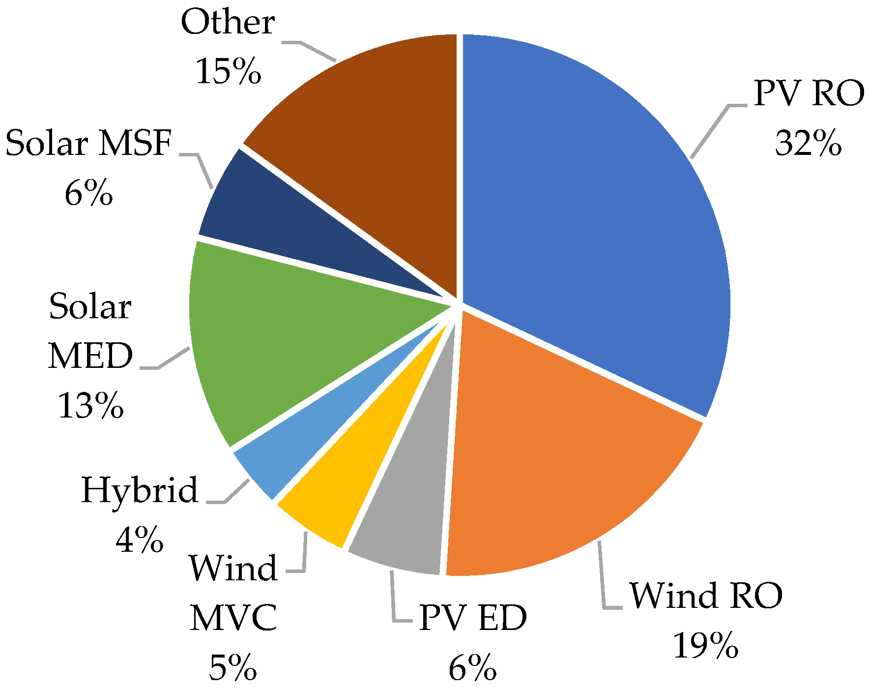
Desalination requires a high amount of energy which is usually provided by fossil fuels. Using renewable energy (RE) sources to operate desalination technologies is a good alternative to decrease the climate impacts of desalination and to produce freshwater in remote regions with severe water scarcity and an unfavorable or impracticable connection to the public electrical grid. Most installed solar, geothermal, and wind or hybrid solar/wind desalination plants have small capacities. Heat or electricity controls membrane and distillation processes, while RE systems generate mechanical energy [50]. Among the renewable energies, solar energy is the most popular and widely used in the world. The reason is that solar energy is available free in the natural form of heat which can be used directly to desalinate and in even greater quantities. It is the most plentiful source available for the Earth, and the cleanest. Arid areas often have a lot of potential for solar energy. Desalination using solar energy is the process in which salt is separated from saltwater (brackish water or saltwater) with the help of solar energy [56]. Solar desalination involves evaporation and condensation. Modern technologies allow both the light and heat of the sun to be employed for energy generation. The main ways to use solar energy directly are by converting solar energy into heat (photothermal—a simple thermal solar collector) or electricity (photovoltaic (PV)/solar cells) using a device (collector, solar cells). The distribution of renewable energy with desalination technology is shown in Figure 6. PV-RO is the most suitable option for desalination.
As shown in Table 3 and Table 4, renewable energy desalination technology is costly compared to conventional desalination technology. Despite the relatively low operating and maintenance costs, the required capital of renewable energy systems is high; consequently, the produced water expense is high [54]. However, with the rapid development of renewable energy technologies, it is expected that the cost will be reduced, and the water production cost will eventually become lower.

2. Materials and Methods

2.1. Life Cycle Analysis (LCA)

2.1.1. Goal and Scope

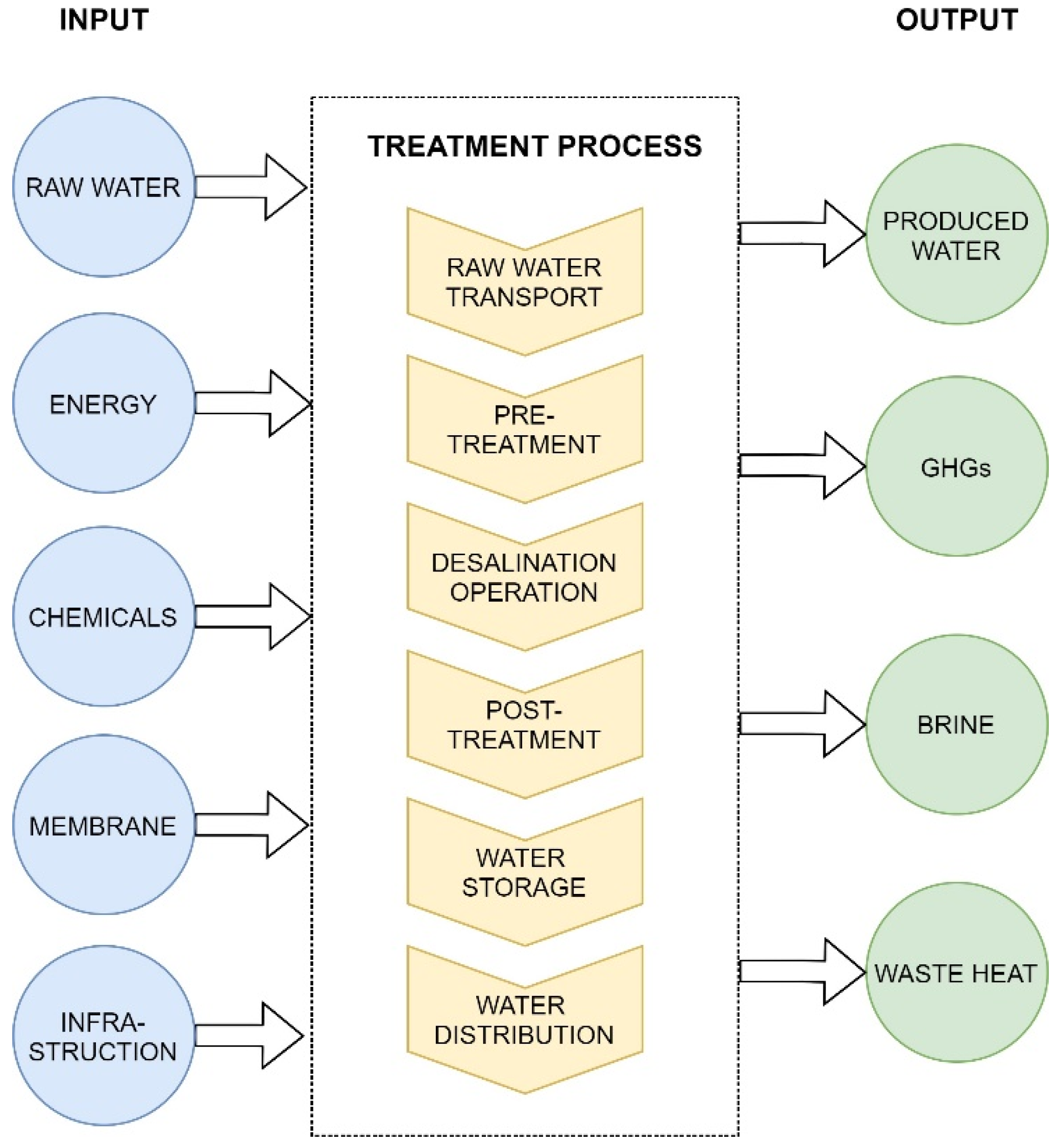
This study compared the three most commonly used desalination processes (MSF, MED, RO) in terms of environmental impacts. Then, it examined how the use of different renewable energy sources and nuclear energy affects the results. This study only considered the operational phase of a plant, which includes the necessary energy and chemical needs, which is called “gate-to-gate” analysis. Irrespective of the type of plant, the operational phase is responsible for a significant part (85–95%) of the environmental impact. Data from Saudi Arabia were used for the analysis, with the base unit of 1 m3 of the water product. The system boundary for each desalination plant is shown in Figure 7.

2.1.2. Inventory Analysis

This study did not include piping systems, pumps, water tanks, and additional units. The emissions from material transportation and construction were also not considered in this study due to data deficiencies and their insignificant impacts [58]. The investment and the plant required for the transport costs and at the end of the life cycle management of waste materials were investigated. The input and output data were collected from an existing study [58] and are listed in Table 5, in which each parameter belongs to the production of 1 m3 of drinking water. The data were based on a report of the Federal Ministry for Environment, Nature Conservation and Nuclear Safety, Germany, in 2007 [58].

2.1.3. Life Cycle Impact Assessment (LCIA)

In the LCIA phase, life cycle inventory data were converted into potential impacts for the product in a quantitative figure by means of characterization factors, based on SimaPro Life Cycle Analysis software version 9.1, which is registered trademark of PRé Sustainability B.V in Netherlands. The following methods of impact analysis and evaluation: IMPACT 2002+ V2.14, ReCiPe 2016 Endpoint (H) V1.02, and IPCC 2013 GWP 100a V1.03, were used in this study.
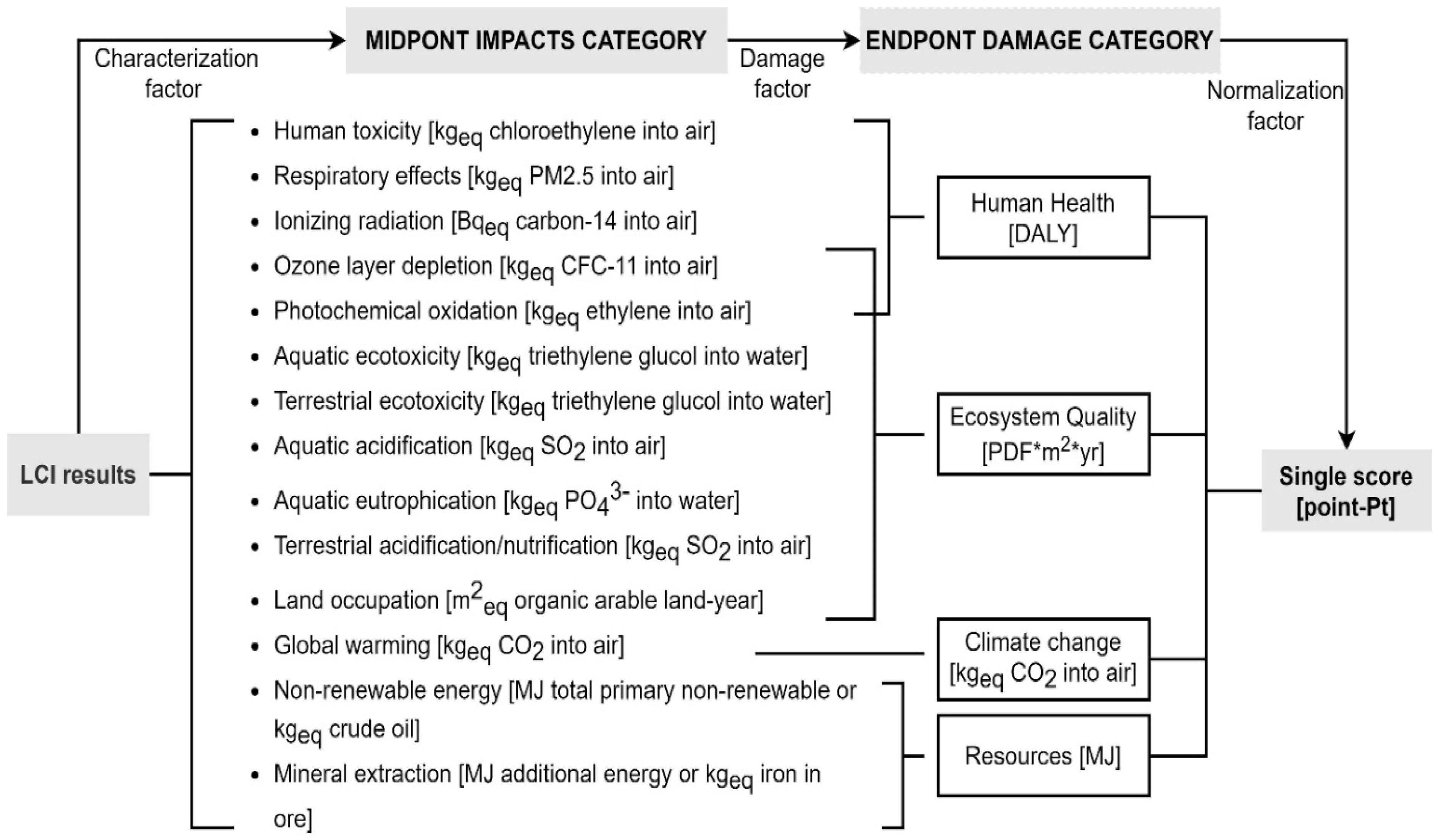
The IMPACT 2002+ methodology combines the midpoint and damage (or endpoint) approaches and links all types of life cycle inventory results via 14 midpoint categories to 4 damage categories (see Figure 8). It allocates these midpoint categories to one or more damage categories and represents changes in the quality of the environment. However, it has some limitations. For instance, several impact categories are not totally considered, such as impacts on the marine environment, noise, ecotoxicity, and human toxicity of metals [59]. The unit of human health damage is DALY (disability-adjusted life-years), i.e., it expresses a number of years of fully healthy life lost [60]. The ecosystem quality indicator is expressed in potentially disappeared fraction (PDF)*m2*year, which is the percentage of species that have become extinct in each area and time period due to environmental loads. The resources indicator is expressed as the surplus energy needed for mineral extraction and non-renewable energy. The climate change indicator is represented by kg CO2eq emission into the air. Normalization makes it easier to interpret the results by comparing each category of the graph with the same units. It also provides an opportunity to discuss the consequences of weighting. It provides an estimate of the magnitude of the weighting factors required to differentiate between different categories. Normalization is performed by dividing the effect (for damage categories) by the appropriate normalization factors (shown in Table 6), which represents the total impact of the specific category divided by the total European or world population. The total impact of the specific category is calculated by summing the products between all European emissions, resource consumption, and the respective damage factors [59]. Table 6 provides an overview of the normalization factors for the four damage categories for Western Europe, which were identified based on the CML impact assessment method for European emissions, referring to the year 2000 [61].
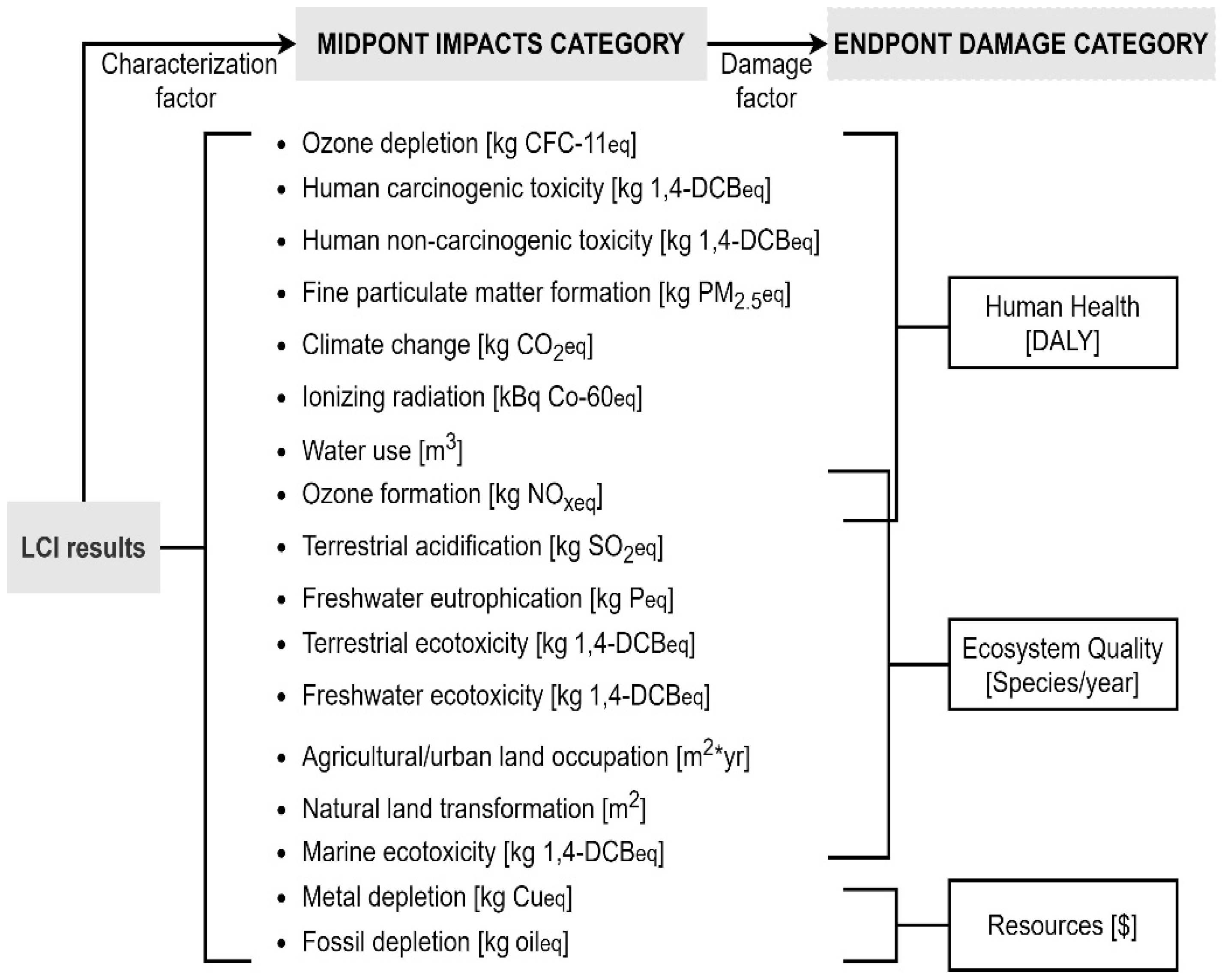
ReCiPe provides harmonized characterization factors at 18 midpoints and 3 endpoints (effect on human health, biodiversity, resource scarcity) that are representative of the global scale according to three perspectives: individualist, hierarchist, and egalitarian [62]. ReCiPe is considered as the broadest set of midpoint impact categories, using global impact mechanisms wherever possible. Unlike other methods (Eco-Indicator 99, EPS, LIME, IMPACT 2002+), the ReCiPe method does not include the possible effects of future extractions but assumes that these effects have been included in the inventory analysis. ReCiPe 2016 is a further development of ReCiPe 2008, with its predecessors CML 2000 and Eco-Indicator 99. Figure 9 shows a scheme of the ReCiPe 2016 framework.
The IPCC 2013 GWP 100a method is an environmental assessment method which expresses the emissions of GHGs generated, in kilograms of CO2 equivalent, over a time horizon of 100 years. The process is much simpler than Eco-Indicator 99, as it only tests one impact category, meaning there is no possible normalization or weighting. It characterizes different gas emissions according to their global warming potential (GWP). Aggregation of different emissions in the climate change impact category is one of the most common methods in LCIA. The GHG emission characterization values are based on the global warming potentials published by the IPCC (Intergovernmental Panel on Climate Change). GWP is proportional to the carbon dioxide effect. GWP is an index for estimating the relative global warming contribution that shows the effect of atmospheric emissions per kilogram of a given greenhouse gas compared to the effect of one kilogram of carbon dioxide emissions [64].

2.2. PESTLE Risk Analysis

PESTLE analysis includes political, economic, social, technological, legal, and environmental factors that could have a direct or long-lasting impact on processes and technologies [65]. PESTLE identifies opportunities and external risks which may be too abstract but should be considered and not ignored. These factors can vary between different regions and countries, but there can be many socio-cultural differences within a country as well. PESTLE is most effective when it is applied from different perspectives. Carrying out a PESTLE analysis should start with collecting the information to answer the following questions: how the government might influence the economy or a certain industry and legal drivers locally, nationally, or internationally (political and legal); how the economy performs (economic); how to affect the community socially (social); how innovations in technology may impact operations and activities (technological); and how to influence the surrounding environment (environmental). PESTLE analysis should be conducted regularly or on an ongoing basis for greater effectiveness. This tool provides the framework for the critical generality evaluation of desalination management [66,67]. However, the previously published literature is only concerned with the economic, social, and environmental factors, or it does not fully analyze the six factors of PESTLE. In this article, desalination technologies were evaluated based on all the factors of PESTLE: political-legal, economic, social, technological, and environmental, from the results of an assessment of environmental and social aspects of the LCA methodology and the documents collected.

2.3. Multi-Criteria Decision Analysis (MCDA)

Multi-criteria decision analysis (MCDA) is an aid tool for this process of decision making, which is able to relatively easily evaluate multiple (conflicting) criteria. Several MCDA approaches have been suggested in order to choose the optimal options, such as MAXMIN, MAXMAX, SAW, AHP, TOPSIS, SMART, and ELECTRE [68]. TOPSIS (Technique for Order Preference by Similarity to the Ideal Solution) is simple, comprehensive, and capable of measuring the relative performance of each alternative from best to worst. TOPSIS’s basic concept is selecting the alternative according to the standard closest to the ideal solution [69]. The classical TOPSIS method relies on numerical data from decision makers, which helps to construct problems and conduct analysis, comparison, and ranking of the alternatives. In this article, MCDA of desalination technologies based on PESTLE analysis with the classical TOPSIS method for a single decision maker was used; thus, the input values must be numerical, in accordance with the following steps [69]:
1. Construction of the normalized decision matrix from decision matrix X = ( x i j ) , where x i j   is the value of i-alternative with respect to j-criterion, and n i j is a normalized value.
n i j = x i j i = 1 m x i j 2 ,   for   i   =   1 ,   2 ,     m ;   j   =   1 ,   2 ,     n
2. Construction of the weighted normalized decision matrix, where v i j is a weighted normalized value.
v i j = w j n i j ,   for   i   =   1 ,   2 ,     m ;   j   =   1 ,   2 ,     n   and   j = 1 n   w j   =   1
3. Determination of the positive ( A + )   and negative ideal solutions ( A ) :
A + = ( v 1 + , v 2 + , , v n + )
where v 1 + , v 2 + ,   v n + are the maximum value of the benefit criteria and the minimum value of the cost criteria;
A = ( v 1 ,   v 2 , , v n )
where v 1 , v 2 ,   v n are the maximum value of the cost criteria and the minimum value of the benefit criteria.
4. Calculation of the separation measure:
d i + = j = 1 n ( v i j v j + ) 2 ,   for   i   =   1 ,   2 ,     m
d i = j = 1 n ( v i j v j ) 2 ,   for   i   =   1 ,   2 ,     m
5. Calculation of the relative closeness to the positive ideal solution:
R i = d i d i + d i + ,   for   i   =   1 ,   2 ,     m
where 0 ≤ Ri ≤ 1.
6. Rank the preference order by selecting the closest to 1 out of the alternatives.

3. Results and Discussion

3.1. Political and Legal Aspects

Political and legal aspects determine the extent to which the government may manipulate a certain industry or the economy. Through tax policies, fiscal policy, trade tariffs, quotas, resources, import–export laws, etc., the government may promote or inhibit the development of industries [65]. The expansion of desalination is shown to be geographically uneven. The leading countries in terms of total installed desalination capacity are the Arabian Gulf countries, such as Saudi Arabia and the UAE. How are the Arabian Gulf countries leading in terms of thermal desalination? In addition to the geographical advantages of the high salinity and temperature of seawater, abundant cheap fuel resources and political policies also greatly contribute to promoting the development of desalination plants. The strategy of the UAE government regarding water security is closely linked to desalination. Therefore, desalination operations’ continuity is ensured. In September 2017, the Ministry of Energy and Infrastructure revealed the UAE Water Security Strategy 2036, which will provide future water needs more sustainably by expanding the use of membrane desalination technologies and the use of renewable energy sources, extending the use of treated wastewater, encouraging water harvesting, and diminishing groundwater extraction [70]. This strategy that promotes the use of solar energy is gaining popularity. Moreover, the UAE government encourages private participation in the development of the country’s infrastructure. In May 2019, the first large-scale solar-powered RO desalination plant, which is worth more than USD 700 million, with the capacity of 909,000 m3/d of seawater, was built at Taweelah, Abu Dhabi, by the Spanish group Abengoa and the Chinese EPC contractor Sepco III. It can be seen that solar-powered RO desalination will become a driving force in the region’s freshwater supplies in the years to come. The UAE aims to boost the share of clean energy in its total energy to 50% by 2050 and decarbonize the electricity sector by 70%, as part of the Energy Strategy 2050 plan.
In Europe, several countries have used desalination of seawater such as Spain, Belgium, and the Netherlands. Spain built Europe’s first desalination plant about 40 years ago and is the leading country of desalination technology in the Western world. The Spanish government saw an opportunity for desalination development, due to its geographical and climatological location. The government created the Actions for the Management and Use of Water (A.G.U.A.) program during the eighth parliamentary term from 2004 to 2008, which was intended to reorient the water policy to meet new needs in the Mediterranean including the construction, expansion, and renovation of a significant number of desalination plants [71]. In addition, the Spanish government also obtained an agreement with the European Commission for the construction of desalination plants, claiming that it was an environmental investment, of which up to 80% of the investment was received from European Cohesion Funds [72]. Article 13 of the Consolidated Text of the Water Act (TRLA in Spanish), which was approved by Royal Legislative Decree 1/2001 July 20th, concerns the laws governing desalination. Both public desalination operations and private initiatives are allowed, and both sections are treated equally as the product of private parties as well as public parties can be used to supply residential buildings, holiday resorts, etc., that lack sufficient resources, and irrigation [71].

3.2. Economic Aspects

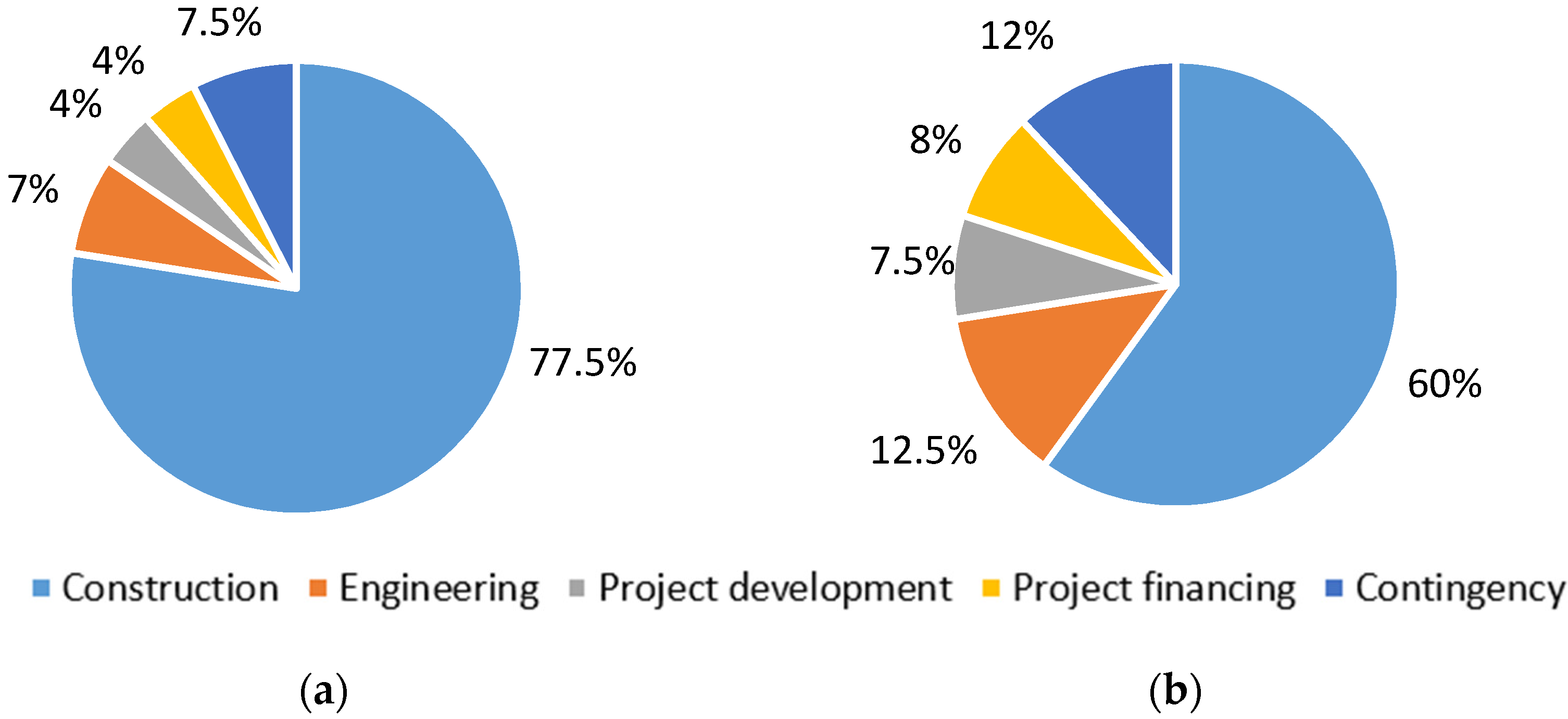
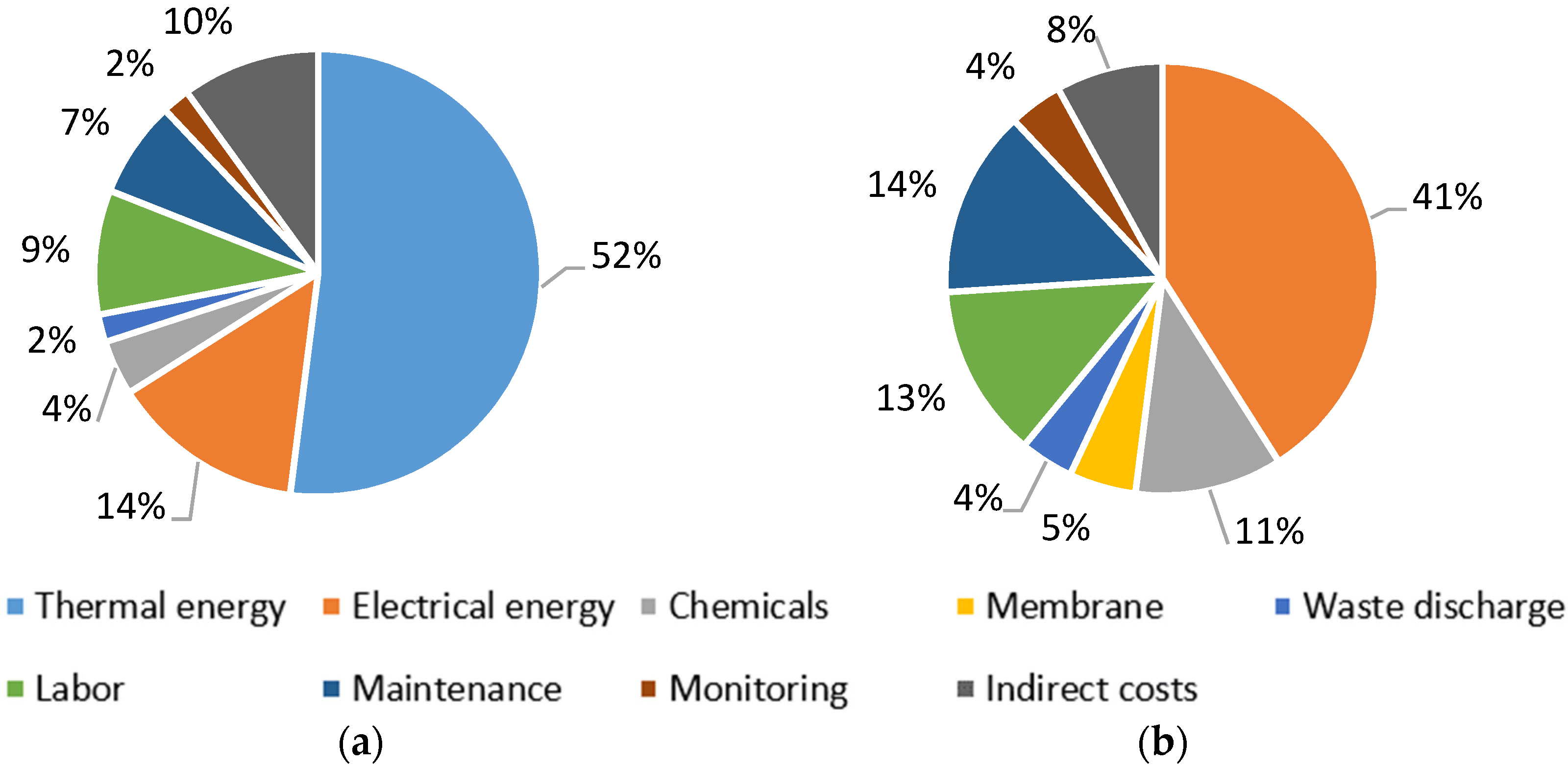
Desalination water product costs depend on the implemented technology, types of material utilized, price of energy within the local area, plant size, and feedwater quality. It is well known that desalination is an energy-intensive process; consequently, the energy cost reserves a significant proportion, up to 30%, of the total cost. Thermal desalination technologies are about 1.53 times more capital-intensive than RO, and the total capital cost of MSF plants is USD 2 million/million liters per day, while that of MED and RO plants is USD 1.5 million and USD 1.3 million, respectively. The operation and maintenance costs of desalination plants by technology are significantly different: the total annual recurrent costs of RO, MSF, and MED plants are about USD 0.2, 0.1, and 0.06 million/million liters per day, respectively [8]. The capital expenditure (CAPEX) and operational expenditure (OPEX) of typical desalination plants are shown in Figure 10 and Figure 11. Compared to the CAPEX of thermal plants (Figure 10a), the construction cost share of total capital costs of RO plants is 17.5% lower, but other costs are higher, such as engineering, project development, financing, and contingency costs. Most of the modern thermal desalination plants in the world are much larger in scale than those of RO technology (see Table 3), meaning construction costs are also higher. The percentage of energy costs in total operational costs of RO technology outperforms that of thermal technology, decreasing from 66% to 41%, (Figure 11). While variable costs (thermal, electrical energy, chemicals, membrane) as a share of the total recurrent costs tend to be higher for thermal technology, the fixed costs (labor, maintenance, other) of RO technology are higher. The cost of desalination is generally associated with technology improvements and the ability to recover more energy from the desalination process.
Additionally, the economic factors are affected by the use of chemicals, market share, research and development investment, the impact of water on the local/national economy, and national and regional political plans [66]. The increasing water scarcity and the growing water demand are expected to increase the demand for desalination globally. The world desalination market was valued at USD 17.7 billion in 2020 and is expected to increase to USD 32.1 billion by 2027. The global desalination industry is predicted to grow with a strong compound annual growth rate (CAGR) of 9.51% from 2020 to 2027 [10].

3.3. Social Aspects

The social aspects consider all factors that affect the market and community socially, including the advantages and disadvantages to the people of the areas in which desalination plants are operated [65]. The social aspect of desalination was investigated with the IMPACT 2002+ V2.14 and ReCiPe 2016 Endpoint (H) V1.02 methods. The damage category is human health, and the impact categories are listed in Figure 8 and Figure 9 and are described in more detail in Section 2.1.3.
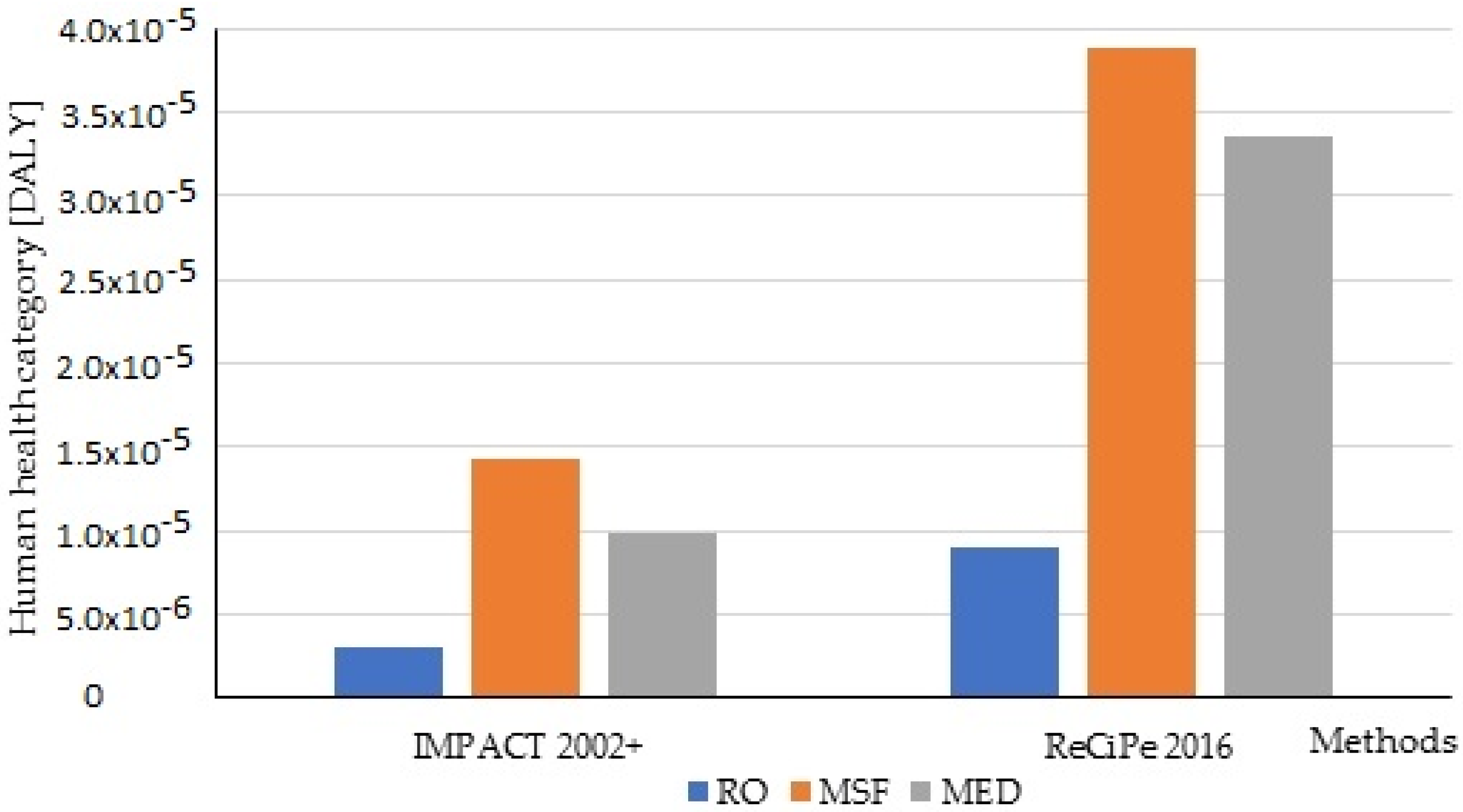
Figure 12 shows a comparison of the base case of the three technologies (RO, MSF, MED) based on the human health damage category of the ReCiPe 2016 and IMPACT 2002+ methods. Table 7 contains the exact values for the human health damage category in the corresponding unit.
Figure 12 presents an observation of the human health damage due to desalination. It shows that RO is the least harmful to human health, with thermal technologies damaging it 3.3–4.8 times more. The results from the two evaluated methods are quite similar: the best is RO, followed by MED, and MSF is in last place. However, the IMPACT 2002+ and ReCiPe 2016 midpoint impact categories and damage pathways are different (see Figure 8 and Figure 9), meaning these values are not the same either. As the analysis was based on 1 m3 of drinking water, it returned rather small values for the human health damage category, but if it is applied to an average capacity plant, which is on the order of 10,000 or even 100,000 m3, it returns a value close to 1 for human health. This means that this would correspond to about 1 year spent in illness. It is important to emphasize that this should not be understood as an individual person but rather considered for the whole population.
We compared these results with the results of Meisam Tabatabaei et al. [73] on LCA for medical mask (surgical and N95 masks) production in China in 2020 based on the IMPACT 2002+ method using SimaPro 9.0.0 software. The estimation of the human health impact of annual medical mask production using fossil-based plastics was 2.03 × 10³ DALY. The equivalent health impact for 1 kg of medical masks was 3.1 × 10⁻⁶ DALY, which is about 0.96, 4.6, and 3.2 times lower than producing 1 m3 of water with the RO, MSF, and MED desalination technologies, respectively. It is worth mentioning that Meisam Tabatabaei et al. considered only raw materials of the production, and the packaging and transportation of masks were not taken into consideration.
Next, the technologies that have caused a shift in traditional energy sources to different energy sources were compared one by one. By default, for thermal technologies, thermal energy was provided by an oil-based thermal power plant, and in all three cases, electricity was covered by the Saudi Arabian electricity mix at the starting points. The comparison with cases where energy needs are covered by nuclear, solar, and wind energy, and for the two distillation methods, also prepares a case where the oil-based thermal power plant is replaced by a natural gas base, which is also typical of Saudi Arabia. Gas-fired power plants are also typical of Saudi Arabia, the proportion of the two types is close to 50–50%, and a desalination plant connected to a gas-fired power plant is also located in the country. The study of nuclear desalination will also play an important role, as Saudi Arabia is currently planning to build two large nuclear reactors that are projected to provide 15% of the current energy needs by 2040. In addition, there are plans to build additional smaller reactors specifically for desalination and to build more than 40 GWe of solar capacity. In addition to solar energy, there are also plenty of opportunities to harness wind energy, as the country has vast land areas. In terms of the nuclear reactor, a pressurized water reactor has provided the energy needs. For this type of reactor, it makes up almost 70% of the reactors operating worldwide, and in the case of nuclear desalination, it is also the most common one that is used. In the case of solar cells, single-crystal and polycrystalline-Si panels were compared; however, a significant difference was not found in the results. Analysis with a polycrystalline-Si solar cell was performed. For thermal processes, two different types of solar collectors were available in the software database (flat plate collector and vacuum tube solar collector) to provide thermal energy. In terms of wind farms, the comparison examined both onshore and offshore wind farms, as their implementation can take place in parallel.
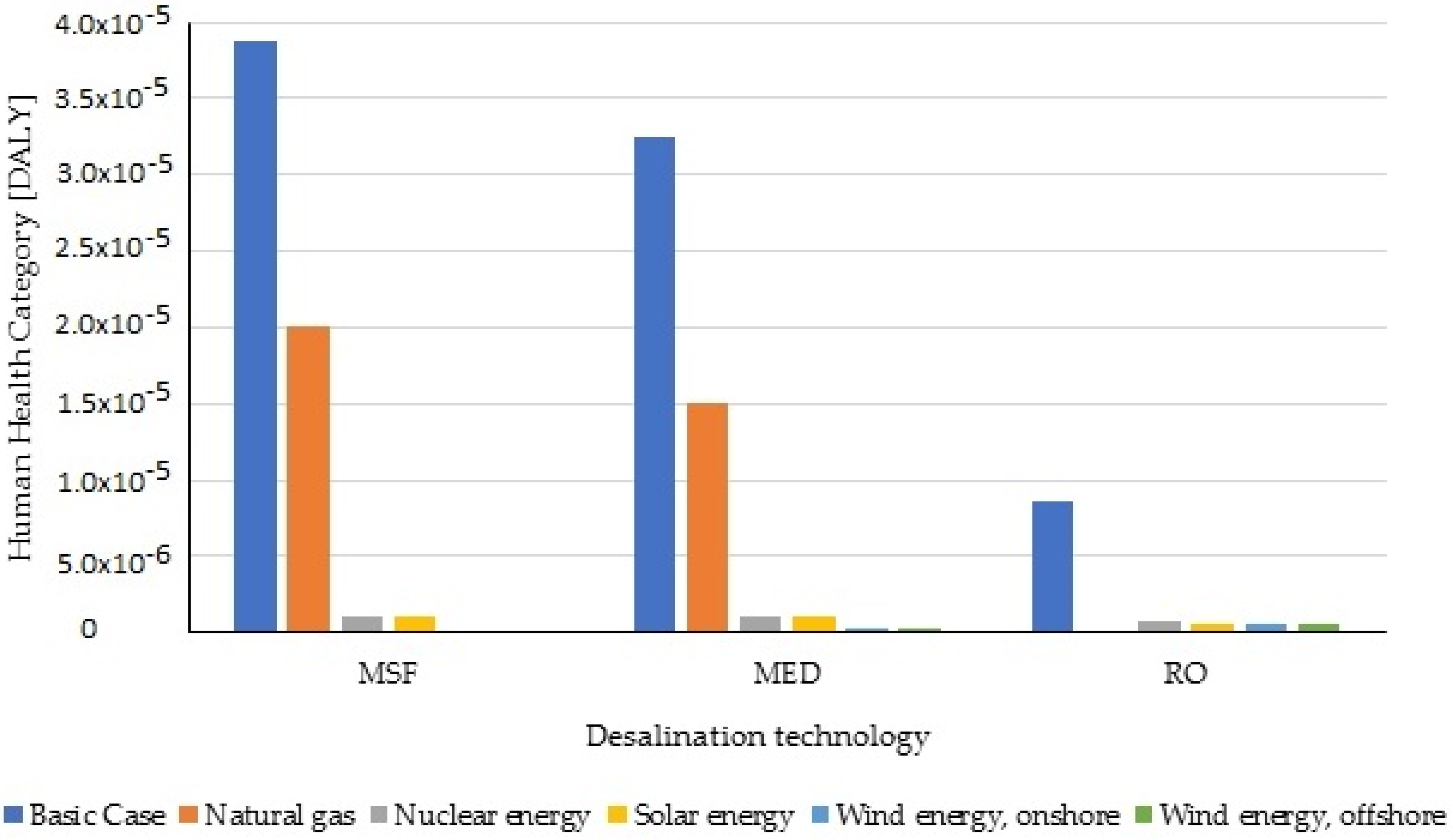
Figure 13 and Figure 14 describe the comparison of desalination technologies used with different energy sources with the human health category based on the ReCiPe 2016 and IMPACT 2002+ methods, and the detailed results are described in Table 8 and Table 9. All in all, in the case of the two distillation processes, switching to a gas-fired and renewable resource power plant already significantly reduces human damage. Wind energy has slightly better results than solar energy. Replacing basic energy sources with renewable or nuclear energy sources significantly reduces the impact on human health. For the MSF technology, the impact reduction is the greatest, e.g., based on the ReCiPe 2016 method, the impact on human health is reduced by 99.72% with onshore wind energy, 99.68% with offshore wind energy, 97.44% with solar energy, 97.16% with nuclear energy, and 48.32% with natural gas. Following the MSF technology is MED, and, finally, RO has the least impact on human health when replacing the used energy source. With RO, there is no big difference when using a combination of wind or solar energy, where it only reduces the impact by about 93%, and nuclear energy decreases it by 92.12%.

3.4. Technological Aspects

The technological factors concerning innovations in technology are transforming the operations of the industry and the market. Some categories that were considered for technological evaluation such as technical features of the desalination plant, typical unit size, energy consumption, CO2 emissions, distillate quality, and unit product cost are listed in Table 3.
In the future, the next generation of RO and MED desalination systems will be focused on improving their performance; more efficient desalination membranes, innovative thermal membranes or hybrid desalination technologies, and improvements have been announced, such as graphene membranes [74] and nanocomposite membranes, e.g., cellulose nanofibers (CNFs) [75,76] and cellulose nanocrystals (CNC) [77]. The low energy consumption is also an advantage compared to other systems. However, the trend of desalination technology development is energy saving, processes, and equipment optimizing, while the current limitations of thermal desalination processes are reducing, the hybridization of technologies, and the combination of renewable energies [3]. Some solutions to the brine discharge problem have been considered, such as near-field and far-field modeling approaches, dilution with cooling water from power plants, environmental monitoring plans (EMPs), zero liquid discharge (ZLD), resource recovery (brine mining), and minimal liquid discharge (MLD). Regarding energy consumption problems, co-generation power–desalination plants, efficient energy usage plants, and energy recovery devices will be a good solution [17]. The use of waste heat (WH) is one of the strategies for the optimization of conventional desalination technologies. It improves productivity and efficiency in the thermal desalination process. The combination of waste heat and/or renewable energy sources generates economic benefits and a healthy environment by eliminating or reducing the input of fuel and energy. This will lead to a reduction in desalination production costs and GHG emissions associated with fuel consumption.
Environmentally friendly “green” antiscalants and corrosion inhibitors are capable alternative chemicals to use in desalination. These substances are phosphorus free and biodegradable, such as polyaspartate (PASP), polyepoxysuccinate (PESA), polyacrylic acid sodium salt (PAAS), and copolymers of maleic and acrylic acid (MA/AA) [78].

3.5. Environmental Aspects

Table 10 describes a summary of the impact assessment results for three desalination technologies: MSF, MED, and RO, using SimaPro software with the IMPACT 2002+, ReCiPe 2016, and IPPC 2013 methods. In the case of the ReCiPe 2016 method, the quality of the ecosystem provides the number of species lost in one year. The reduction in resources is expressed in US dollars. A significant part of the reduction in resources is also determined by the energy used, as shown by the individual prices; in the case of the two thermal technologies, it is about USD 1.79–2.20, but in the case of RO—where no heating is required—it is only about USD 0.61. In the case of IMPACT 2002+, the numbers for the ecosystem are already much higher, which shows us how many species we can lose per square meter in one year. In this case, too, this large-scale degradation is largely due to the use of non-renewable energy sources, which is more significant for the two thermal technologies due to their much higher energy requirements. This trend can also be observed in the results on climate change and resources, correlated with the energy needs of the technologies. In the case of the IPCC 2013 method, the time for monitoring the effects is set at 100 years. In terms of the results, this method returns almost the same values as IMPACT 2002+ for the climate change category. In this case, the main source is the energy demand of the processes, and the values increase proportionally. Compared with previously published results (Table 3), the results of this paper have a difference in the absolute value of CO2 emissions of the studied technologies, but they are similar in arrangement. MSF emits the most CO2, three–four times higher than that emitted by RO, followed by MED, two–three times higher than that emitted by RO. Overall, RO has the least pollution, and the two thermal technologies return nearly similar results.
Table 11, Table 12 and Table 13 show the comparison of the desalination technologies used with different energy sources: fossil energy, solar energy, wind energy, and nuclear energy. All in all, in the case of the two distillation processes, switching to a gas-fired power plant already reduces pollution. There is not much difference between climate change and resource depletion, but the improvement in ecosystem quality is already more significant.
Looking at the results, in the RO case, it can be said that drastic reductions can already be achieved by using nuclear energy instead of fossil fuels. In general, these results are already comparable to renewables. This case returns slightly higher values for ecosystem quality than renewables but is significantly more environmentally friendly than fossil fuels. However, in the cases of MSF and MED, nuclear energy is only beneficial in terms of the environment, with ecosystem quality being almost equal, and in terms of resources, it is much worse than fossil fuel. In terms of carbon dioxide emissions, the difference compared to renewables is even smaller, and in some cases, it is fully comparable with solar energy. An exception, in this case, is the resource results of IMPACT 2002+, which are almost doubled compared to the fossil fuel cases. This increase is due to the fact that the rate of resource reduction in this method is given in MJ, which gives the amount of energy needed to produce energy and extract the energy source. However, with the ReCiPe 2016 method, the rate of reduction in energy resources is given in US dollars, and thus operating with nuclear power proves to be cheaper than fossil fuels.
With regard to renewable energy sources, it can also be said, in general, that there is a huge improvement in all methods and damage categories. Wind energy returned slightly better results than solar energy. Within wind energy, there is no significant difference between onshore and offshore power plants in either case. Therefore, in terms of the operational phase, and apart from other conditions, wind energy can be said to be the most environmentally friendly. The combination of wind energy and MSF technology obtains the best improvement, where it can reduce 99.7% of CO2 emissions into the environment, from 16.371 kg CO2 eq in the case of the basic case to 0.038 kg CO2 eq if replaced by onshore wind energy. This combination is followed by MED technology, which reduces CO2 emissions into the environment by 99.5%, and, finally, RO, with only a 96.5% reduction. Thermal desalination requires a much larger amount of energy than membrane technology, meaning that if that energy is replaced with renewable energy, the environmental, ecosystem, and resource impact will be even greater.

3.6. MCDA Results

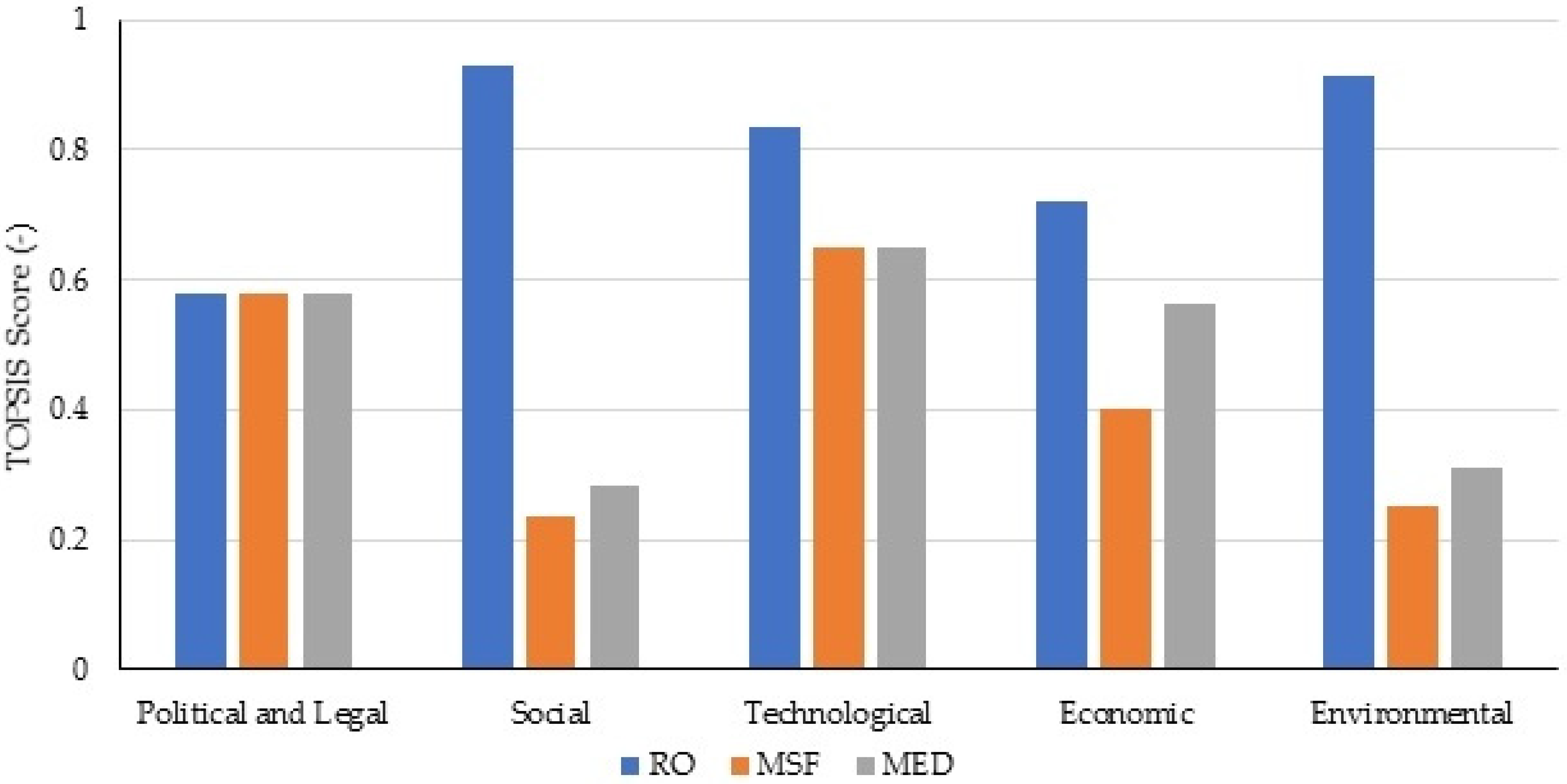
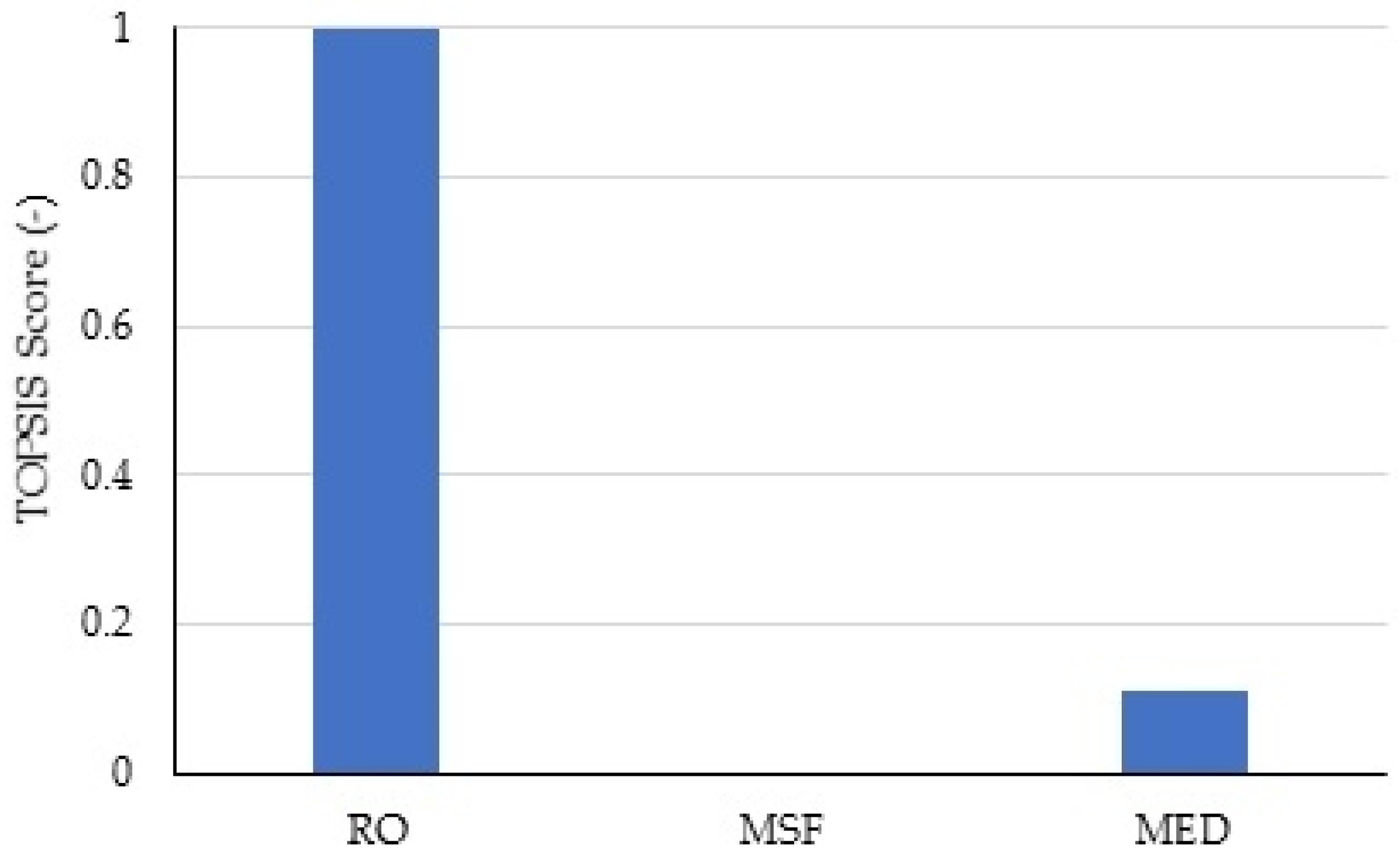
The investigated PESTLE factors were used as numerical input for MCDA, in which the social and environmental factors were derived from the impact assessment results based on the IMPACT 2002+ method (see Table 14); political and legal, technological, and economic factors were evaluated by their TOPSIS score, where a higher score is better (Table 15). The political and legal review demonstrates that, considering the development of desalination technology is the same, there is not much difference between countries in the Western Europe region. The assessment of the economical factor was based on previously published unit product costs (see Table 3). The price of 1 m3 of clean water from the RO technology is the cheapest (0.52–0.56 USD/m3), followed by MED (0.52–1.01 USD/m3) and, finally, MSF (0.52–1.75 USD/m3). The future trend of the RO technology was evaluated to have potential, meaning RO is given a higher score than the other two technologies in the technology factor. The MCDA results of the PESTLE factors with TOPSIS score was described in Figure 15.
The weight of the criterion was determined and is shown in Table 16. The weight of factors is a subjective input, which is usually not even and strongly depends on the personal opinion of the decision maker. In this paper, the environmental factor was considered as the leading factor with the biggest weight, followed by the social and economic factors. Finally, technological, political, and legal factors were the least important factors.
The final result of the MCDA is shown in Figure 16. The best alternative was found to be RO with a TOPSIS score of 1.00. RO was followed by MED with a score of 0.11. The evaluation shows that the worst alternative is the MSF-based technology. The TOPSIS score of MSF is zero because all of its factor levels were evaluated as negative ideal solutions.

4. Conclusions

This analysis compared the base cases of three technologies: MSF, MED, and RO, in which fossil fuels provided the energy requirements for the studied processes. Overall, the results of the effect categories of the different impact analysis procedures follow a similar trend, where it is shown that RO using basic fossil energy was the most environmentally friendly, having the lowest impact on the ecosystem, resources, and human health. It is important to note that this analysis only examined the operational phase. The price of 1 m3 of clean water from the RO technology is cheaper than MSF and MED. On the other hand, it can be said that these distillation methods are already well-developed technologies, and no significant development is expected, in contrast to membrane technology, in which there is still a lot of potential, and there is continuous development in this field. This is also confirmed by the worldwide trend, with RO increasingly taking over the desalination market. However, during the distillation plant lifetime and operation, this does not require any serious intervention other than mandatory maintenance operations. In contrast, during RO, membrane processes frequently encounter scaling/fouling problems, and their lifespan is currently 5–7 years.
As far as energy sources are concerned, switching from a fossil energy source to any other energy source reduced the value of the damage categories by at least an order of magnitude. Renewable energy sources (solar and wind energy) showed a similarly huge improvement compared to the base cases, returning even slightly more favorable values compared to nuclear energy. However, no significant difference was found between solar and wind energy. Their great advantage is that after the investment, their operation does not involve any emissions, but the investment cost itself is high. The biggest drawback is that the availability of these energy sources is far from constant but seasonal, and since the problem of energy storage is currently unresolved, we cannot rely solely on renewables. It should also be taken into account that the lifespan of these power plants is much shorter than that of a conventional power plant. Additionally, this also calls into question their economic efficiency.
These problems do not exist in the case of nuclear power plants, where the nuclear energy itself is cheap, no carbon dioxide is produced during nuclear fission, and nuclear energy provides a constant source of energy. However, their disadvantage is that they are not very popular in the public consciousness, their operation generates radioactive waste, which must be safely disposed of for a long period, and the start-up and shut-down of nuclear power plants are both complicated operations.
There is currently no unique solution to this issue, and energy diversification is needed. The use of renewables is indeed a step forward, but until the issue of energy storage is resolved, it cannot be overly proportionate because it will render the system unstable. It is therefore important that we seize every opportunity and do so as effectively as possible. The greatest potential can be seen with RO combined with various energy sources; this technology may still evolve in the future to produce longer-lasting, cheaper membranes, and the energy requirements of this process are steadily declining over the years thanks to modern energy recovery systems.

Author Contributions

Conceptualization, H.T.D.T.; writing—review and editing, T.P. and D.F.; methodology, F.M.; investigation, A.J.T.; supervision. All authors have read and agreed to the published version of the manuscript.

Funding

This publication was supported by NTP-NFTÖ-21-B-0014 National Talent Program of the Cabinet Office of the Prime Minister, OTKA 128543 and 131586. This research was supported by the EU LIFE program, LIFE-CLIMCOOP project (LIFE19 CCA/HU/001320). The research reported in this paper and carried out at the Budapest University of Technology and Economics was supported by the National Research Development and Innovation Fund (TKP2020 National Challenges Subprogram, Grant No. BME-NC) based on the charter of bolster issued by the National Research Development and Innovation Office under the auspices of the Ministry for Innovation and Technology. This research work was carried out with the support of the Hungarian Government as part of the Hungarian State Eötvös Scholarship provided by the Tempus Public Foundation.

Conflicts of Interest

The authors declare no conflict of interest.

Abbreviations

ROReverse Osmosis
MSFMulti-Stage Flash Distillation
MEDMulti-Effect Distillation
TVCThermal Vapor Compression
MFMicrofiltration
UFUltrafiltration
NFNanofiltration
MBMembrane Bioreactor
MDMembrane Distillation
EDElectrodialysis
FOForward Osmosis
PVPhotovoltaic
RERenewable Energy
TDSTotal Dissolved Solids
LCALife Cycle Analysis
LCIALife Cycle Impact Assessment
DALYDisability-Adjusted Life-Years
PDFPotentially Disappeared Fraction
MCDAMulti-Criteria Decision Analysis
TOPSISTechnique for Order Preference by Similarity to the Ideal Solution
GWPGlobal Warming Potential
CAPEXCapital Expenditure
OPEXOperational Expenditure

References

  1. Rajasulochana, P.; Preethy, V. Comparison on efficiency of various techniques in treatment of waste and sewage water—A comprehensive review. Resour. Effic. Technol. 2016, 2, 175–184. [Google Scholar] [CrossRef] [Green Version]
  2. Esmaeilion, F. Hybrid renewable energy systems for desalination. Appl. Water Sci. 2020, 10, 84. [Google Scholar] [CrossRef] [Green Version]
  3. Feria-Díaz, J.; Maria Cristina, L.-M.; Sandoval-Herazo, L.; Correa Mahecha, F.; Rodriguez Miranda, J. Commercial Thermal Technologies for Desalination of Water from Renewable Energies: A State of the Art Review. Processes 2020, 9, 262. [Google Scholar] [CrossRef]
  4. Caldera, U.; Bogdanov, D.; Breyer, C. Local cost of seawater RO desalination based on solar PV and wind energy: A global estimate. Desalination 2016, 385, 207–216. [Google Scholar] [CrossRef]
  5. Li, C.; Goswami, Y.; Stefanakos, E. Solar assisted sea water desalination: A review. Renew. Sustain. Energy Rev. 2013, 19, 136–163. [Google Scholar] [CrossRef]
  6. Nair, M.; Kumar, D. Water desalination and challenges: The Middle East perspective: A review. Desalination Water Treat. 2013, 51, 2030–2040. [Google Scholar] [CrossRef]
  7. Eke, J.; Yusuf, A.; Giwa, A.; Sodiq, A. The global status of desalination: An assessment of current desalination technologies, plants and capacity. Desalination 2020, 495, 114633. [Google Scholar] [CrossRef]
  8. Voutchkov, N. The Role of Desalination in an Increasingly Water-Scarce World; World Bank Group: Washington, DC, USA, 2019. [Google Scholar]
  9. Jones, E.; Qadir, M.; van Vliet, M.; Smakhtin, V.; Kang, S.-M. The state of desalination and brine production: A global outlook. Sci. Total Environ. 2019, 657, 1343–1356. [Google Scholar] [CrossRef]
  10. Markets, R.A. Global Desalination Market by Regions, Technology, Application, Company, Analysis, Forecast; Research and Markets: Dublin, Ireland, 2021; p. 100. [Google Scholar]
  11. Álvarez, V.; Gonzalez-Ortega, M.; Martin-Gorriz, B.; Soto Garcia, M.; Maestre, J. Seawater desalination for crop irrigation-Current status and perspectives. J. Appl. Biomater. Biomech. 2018, 1, 461–492. [Google Scholar] [CrossRef]
  12. Suwaileh, W.; Johnson, D.; Hilal, N. Membrane desalination and water re-use for agriculture: State of the art and future outlook. Desalination 2020, 491, 114559. [Google Scholar] [CrossRef]
  13. Elsaid, K.; Kamil, M.; Sayed, E.T.; Abdelkareem, M.A.; Wilberforce, T.; Olabi, A. Environmental impact of desalination technologies: A review. Sci. Total Environ. 2020, 748, 141528. [Google Scholar] [CrossRef]
  14. Elsaid, K.; Sayed, E.T.; Abdelkareem, M.A.; Mahmoud, M.S.; Ramadan, M.; Olabi, A.G. Environmental impact of emerging desalination technologies: A preliminary evaluation. J. Environ. Chem. Eng. 2020, 8, 104099. [Google Scholar] [CrossRef]
  15. Ahmadvand, S.; Abbasi, B.; Azarfar, B.; Elhashimi, M.; Zhang, X.; Abbasi, B. Looking Beyond Energy Efficiency: An Applied Review of Water Desalination Technologies and an Introduction to Capillary-Driven Desalination. Water 2019, 11, 696. [Google Scholar] [CrossRef] [Green Version]
  16. Kim, D.H. A review of desalting process techniques and economic analysis of the recovery of salts from retentates. Desalination 2011, 270, 1–8. [Google Scholar] [CrossRef]
  17. Panagopoulos, A.; Haralambous, K.-J. Environmental impacts of desalination and brine treatment-Challenges and mitigation measures. Mar. Pollut. Bull. 2020, 161, 111773. [Google Scholar] [CrossRef]
  18. Cambridge, M.L.; Zavala-Perez, A.; Cawthray, G.R.; Mondon, J.; Kendrick, G.A. Effects of high salinity from desalination brine on growth, photosynthesis, water relations and osmolyte concentrations of seagrass Posidonia australis. Mar. Pollut. Bull. 2017, 115, 252–260. [Google Scholar] [CrossRef] [PubMed]
  19. Missimer, T.M.; Maliva, R.G. Environmental issues in seawater reverse osmosis desalination: Intakes and outfalls. Desalination 2018, 434, 198–215. [Google Scholar] [CrossRef]
  20. Li, H.; Shi, A.; Li, M.; Zhang, X. Effect of pH, Temperature, Dissolved Oxygen, and Flow Rate of Overlying Water on Heavy Metals Release from Storm Sewer Sediments. J. Chem. 2013, 2013, 434012. [Google Scholar] [CrossRef]
  21. Wiltshire, K.H.; Kraberg, A.; Bartsch, I.; Boersma, M.; Franke, H.-D.; Freund, J.; Gebühr, C.; Gerdts, G.; Stockmann, K.; Wichels, A. Helgoland Roads, North Sea: 45 Years of Change. Estuaries Coasts 2010, 33, 295–310. [Google Scholar] [CrossRef] [Green Version]
  22. Wood, J.E.; Silverman, J.; Galanti, B.; Biton, E. Modelling the distributions of desalination brines from multiple sources along the Mediterranean coast of Israel. Water Res. 2020, 173, 115555. [Google Scholar] [CrossRef]
  23. Kenigsberg, C.; Abramovich, S.; Hyams-Kaphzan, O. The effect of long-term brine discharge from desalination plants on benthic foraminifera. PLoS ONE 2020, 15, e0227589. [Google Scholar] [CrossRef] [PubMed] [Green Version]
  24. Hosseini, H.; Saadaoui, I.; Moheimani, N.; Al Saidi, M.; Al Jamali, F.; Al Jabri, H.; Hamadou, R.B. Marine health of the Arabian Gulf: Drivers of pollution and assessment approaches focusing on desalination activities. Mar. Pollut. Bull. 2021, 164, 112085. [Google Scholar] [CrossRef] [PubMed]
  25. Panagopoulos, A.; Haralambous, K.-J.; Loizidou, M. Desalination brine disposal methods and treatment technologies—A review. Sci. Total Environ. 2019, 693, 133545. [Google Scholar] [CrossRef]
  26. Alshahri, F. Heavy metal contamination in sand and sediments near to disposal site of reject brine from desalination plant, Arabian Gulf: Assessment of environmental pollution. Environ. Sci. Pollut. Res. 2017, 24, 1821–1831. [Google Scholar] [CrossRef]
  27. Mohamed, A.M.O.; Maraqa, M.; Al Handhaly, J. Impact of land disposal of reject brine from desalination plants on soil and groundwater. Desalination 2005, 182, 411–433. [Google Scholar] [CrossRef]
  28. Ahlgren, J.; Grimvall, A.; Omstedt, A.; Rolff, C.; Wikner, J. Temperature, DOC level and basin interactions explain the declining oxygen concentrations in the Bothnian Sea. J. Mar. Syst. 2017, 170, 22–30. [Google Scholar] [CrossRef]
  29. Guo, P.; Li, T.; Wang, Y.; Li, J. Energy and exergy analysis of a spray-evaporation multi-effect distillation desalination system. Desalination 2021, 500, 114890. [Google Scholar] [CrossRef]
  30. Voutchkov, N. Energy use for membrane seawater desalination–current status and trends. Desalination 2018, 431, 2–14. [Google Scholar] [CrossRef]
  31. Nassrullah, H.; Anis, S.F.; Hashaikeh, R.; Hilal, N. Energy for desalination: A state-of-the-art review. Desalination 2020, 491, 114569. [Google Scholar] [CrossRef]
  32. Woo, Y.C.; Kim, S.-H.; Shon, H.K.; Tijing, L.D. Introduction: Membrane Desalination Today, Past, and Future. In Current Trends and Future Developments on (Bio-) Membranes; Basile, A., Curcio, E., Inamuddin, D., Eds.; Elsevier: Amsterdam, The Netherlands, 2019; pp. xxv–xlvi. [Google Scholar] [CrossRef]
  33. Kress, N. Chapter 2-Desalination Technologies. In Marine Impacts of Seawater Desalination; Kress, N., Ed.; Elsevier: Amsterdam, The Netherlands, 2019; pp. 11–34. [Google Scholar] [CrossRef]
  34. Saadat, A.H.M.; Islam, M.S.; Islam, M.; Fahmida, P.; Sultana, A. Desalination Technologies for Developing Countries: A Review. J. Sci. Res. 2018, 10, 77–97. [Google Scholar] [CrossRef] [Green Version]
  35. Likhachev, D.; Li, F.-C. Large-scale water desalination methods: A review and new perspectives. Desalination Water Treat. 2013, 51, 2836–2849. [Google Scholar] [CrossRef]
  36. Toth, A.J. Modelling and Optimisation of Multi-Stage Flash Distillation and Reverse Osmosis for Desalination of Saline Process Wastewater Sources. Membranes 2020, 10, 265. [Google Scholar] [CrossRef]
  37. Anand, B.; Shankar, R.; Murugavelh, S.; Rivera, W.; Midhun Prasad, K.; Nagarajan, R. A review on solar photovoltaic thermal integrated desalination technologies. Renew. Sustain. Energy Rev. 2021, 141, 110787. [Google Scholar] [CrossRef]
  38. Maton, L.; Psarras, G.; Kasapakis, G.; Ravn Lorenzen, J.; Andersen, M.; Boesen, M.; Nøhr Bak, S.; Chartzoulakis, K.; Marcus Pedersen, S.; Kloppmann, W. Assessing the net benefits of using wastewater treated with a membrane bioreactor for irrigating vegetables in Crete. Agric. Water Manag. 2010, 98, 458–464. [Google Scholar] [CrossRef]
  39. Xie, M.; Shon, H.K.; Gray, S.R.; Elimelech, M. Membrane-based processes for wastewater nutrient recovery: Technology, challenges, and future direction. Water Res. 2016, 89, 210–221. [Google Scholar] [CrossRef] [PubMed] [Green Version]
  40. Abou-Shady, A. Recycling of polluted wastewater for agriculture purpose using electrodialysis: Perspective for large scale application. Chem. Eng. J. 2017, 323, 1–18. [Google Scholar] [CrossRef]
  41. Campione, A.; Gurreri, L.; Ciofalo, M.; Micale, G.; Tamburini, A.; Cipollina, A. Electrodialysis for water desalination: A critical assessment of recent developments on process fundamentals, models and applications. Desalination 2018, 434, 121–160. [Google Scholar] [CrossRef]
  42. Voutchkov, N. Considerations for selection of seawater filtration pretreatment system. Desalination 2010, 261, 354–364. [Google Scholar] [CrossRef]
  43. Wafi, M.K.; Hussain, N.; El-Sharief Abdalla, O.; Al-Far, M.D.; Al-Hajaj, N.A.; Alzonnikah, K.F. Nanofiltration as a cost-saving desalination process. SN Appl. Sci. 2019, 1, 751. [Google Scholar] [CrossRef] [Green Version]
  44. Greenlee, L.F.; Lawler, D.F.; Freeman, B.D.; Marrot, B.; Moulin, P. Reverse osmosis desalination: Water sources, technology, and today’s challenges. Water Res. 2009, 43, 2317–2348. [Google Scholar] [CrossRef] [PubMed]
  45. Sablani, S.S.; Goosen, M.F.A.; Al-Belushi, R.; Wilf, M. Concentration polarization in ultrafiltration and reverse osmosis: A critical review. Desalination 2001, 141, 269–289. [Google Scholar] [CrossRef]
  46. Curto, D.; Franzitta, V.; Guercio, A. A Review of the Water Desalination Technologies. Appl. Sci. 2021, 11, 670. [Google Scholar] [CrossRef]
  47. Mansour, T.M.; Ismail, T.M.; Ramzy, K.; Abd El-Salam, M. Energy recovery system in small reverse osmosis desalination plant: Experimental and theoretical investigations. Alex. Eng. J. 2020, 59, 3741–3753. [Google Scholar] [CrossRef]
  48. Miller, S.; Shemer, H.; Semiat, R. Energy and environmental issues in desalination. Desalination 2015, 366, 2–8. [Google Scholar] [CrossRef]
  49. Washahi, M.A.; Gopinath, A.S. Techno Economical Feasibility Analysis of Solar Powered RO Desalination in Sultanate of Oman. In Proceedings of the 2017 9th IEEE-GCC Conference and Exhibition (GCCCE), Manama, Bahrain, 8–11 May 2017; pp. 1–9. [Google Scholar]
  50. Cherif, H.; Belhadj, J. Chapter 15-Environmental Life Cycle Analysis of Water Desalination Processes. In Sustainable Desalination Handbook; Gude, V.G., Ed.; Butterworth-Heinemann: Oxford, UK, 2018; pp. 527–559. [Google Scholar] [CrossRef]
  51. Abdelkareem, M.A.; El Haj Assad, M.; Sayed, E.T.; Soudan, B. Recent progress in the use of renewable energy sources to power water desalination plants. Desalination 2018, 435, 97–113. [Google Scholar] [CrossRef]
  52. Al-Karaghouli, A.; Kazmerski, L.L. Energy consumption and water production cost of conventional and renewable-energy-powered desalination processes. Renew. Sustain. Energy Rev. 2013, 24, 343–356. [Google Scholar] [CrossRef]
  53. Al Bloushi, A.; Giwa, A.; Mezher, T.; Hasan, S.W. Chapter 3-Environmental Impact and Technoeconomic Analysis of Hybrid MSF/RO Desalination: The Case Study of Al Taweelah A2 Plant. In Sustainable Desalination Handbook; Gude, V.G., Ed.; Butterworth-Heinemann: Oxford, UK, 2018; pp. 55–97. [Google Scholar] [CrossRef]
  54. Hamed, O.A. Overview of hybrid desalination systems—Current status and future prospects. Desalination 2005, 186, 207–214. [Google Scholar] [CrossRef]
  55. Kamal, I. Myth and reality of the hybrid desalination process. Desalination 2008, 230, 269–280. [Google Scholar] [CrossRef]
  56. Chauhan, V.K.; Shukla, S.K.; Tirkey, J.V.; Singh Rathore, P.K. A comprehensive review of direct solar desalination techniques and its advancements. J. Clean. Prod. 2021, 284, 124719. [Google Scholar] [CrossRef]
  57. Aziz, N.I.H.A.; Hanafiah, M.M. Application of life cycle assessment for desalination: Progress, challenges and future directions. Environ. Pollut. 2021, 268, 115948. [Google Scholar] [CrossRef] [PubMed]
  58. Team, A.-C. Concentrating Solar Power for Seawater Desalination; Federal Ministry for the Environment, Nature Conservation and Nuclear Safety: Stuttgart, Germany, 2007.
  59. Jolliet, O.; Margni, M.; Charles, R.; Humbert, S.; Payet, J.; Rebitzer, G.; Rosenbaum, R. IMPACT 2002+: A new life cycle assessment methodology. Int. J. Life Cycle Assess. 2003, 8, 324–330. [Google Scholar] [CrossRef] [Green Version]
  60. WHO. Indicator Metadata Registry List. Available online: www.who.int/data/gho/indicator-metadata-registry (accessed on 10 August 2021).
  61. Benini, L.; Mancini, L.; Sala, S.; Manfredi, S.; Schau, E.; Pant, R. Normalisation Method and Data for Environmental Footprints; Publications Office of the European Union: Luxembourg, 2014. [Google Scholar] [CrossRef]
  62. Huijbregts, M.; Steinmann, Z.; Elshout, P.; Stam, G.; Verones, F.; Vieira, M.; Zijp, M.; Hollander, A.; Zelm, R. ReCiPe2016: A harmonised life cycle impact assessment method at midpoint and endpoint level. Int. J. Life Cycle Assess. 2016, 22, 138–147. [Google Scholar] [CrossRef]
  63. Catalán, E.; Sánchez, A. Solid-State Fermentation (SSF) Versus Submerged Fermentation (SmF) for the Recovery of Cellulases from Coffee Husks: A Life Cycle Assessment (LCA) Based Comparison. Energies 2020, 13, 2685. [Google Scholar] [CrossRef]
  64. Hischier, R.; Weidema, B.; Althaus, H.-J.; Bauer, C.; Doka, G.; Dones, R.; Frischknecht, R.; Hellweg, S.; Humbert, S.; Jungbluth, N.; et al. Implementation of Life Cycle Impact Assessment Methods; Swiss Centre for Life Cycle Inventories: St. Gallen, Switzerland, 2010. [Google Scholar]
  65. Nitank Rastogi, D.M.K.T. PESTLE Technique—A tool to identify external risks in construction projects. Int. Res. J. Eng. Technol. (IRJET) 2016, 3, 384–388. [Google Scholar]
  66. Rustum, R.; Kurichiyanil, A.M.; Forrest, S.; Sommariva, C.; Adeloye, A.J.; Zounemat-Kermani, M.; Scholz, M. Sustainability Ranking of Desalination Plants Using Mamdani Fuzzy Logic Inference Systems. Sustainability 2020, 12, 631. [Google Scholar] [CrossRef] [Green Version]
  67. March, H. The politics, geography, and economics of desalination: A critical review: Politics, geography, and economics of desalination. WIREs Water 2015, 2, 231–243. [Google Scholar] [CrossRef]
  68. Roszkowska, E. Multi-criteria Decision Making Models by Applying the Topsis Method to Crisp and Interval Data. Mult. Criteria Decis. Mak. 2011, 6, 200–230. [Google Scholar]
  69. Balioti, V.; Tzimopoulos, C.; Evangelides, C. Multi-Criteria Decision Making Using TOPSIS Method Under Fuzzy Environment. Application in Spillway Selection. Proceedings 2018, 2, 637. [Google Scholar] [CrossRef] [Green Version]
  70. United Arab Emirates Ministry of Emergy and Infrastructure. Available online: https://www.moei.gov.ae/default.aspx (accessed on 3 May 2021).
  71. Navarro, T. Water reuse and desalination in Spain–challenges and opportunities. J. Water Reuse Desalination 2018, 8, 153–168. [Google Scholar] [CrossRef] [Green Version]
  72. Arahuetes, A.; Villar Navascués, R. Desalination, a strategic and controversial resource in Spain. WIT Trans. Ecol. Environ. 2017, 216, 61–72. [Google Scholar] [CrossRef] [Green Version]
  73. Tabatabaei, M.; Hosseinzadeh-Bandbafha, H.; Yang, Y.; Aghbashlo, M.; Lam, S.S.; Montgomery, H.; Peng, W. Exergy intensity and environmental consequences of the medical face masks curtailing the COVID-19 pandemic: Malign bodyguard? J. Clean. Prod. 2021, 313, 127880. [Google Scholar] [CrossRef] [PubMed]
  74. Homaeigohar, S.; Elbahri, M. Graphene membranes for water desalination. NPG Asia Mater. 2017, 9, e427. [Google Scholar] [CrossRef] [Green Version]
  75. Ma, H.; Burger, C.; Hsiao, B.; Chu, B. Ultra-fine cellulose nanofibers: New nano-scale materials for water purification. J. Mater. Chem. 2011, 21, 7507–7510. [Google Scholar] [CrossRef]
  76. Liu, S.; Low, Z.-X.; Hegab, H.M.; Xie, Z.; Ou, R.; Yang, G.; Simon, G.P.; Zhang, X.; Zhang, L.; Wang, H. Enhancement of desalination performance of thin-film nanocomposite membrane by cellulose nanofibers. J. Membr. Sci. 2019, 592, 117363. [Google Scholar] [CrossRef]
  77. Smith, E.; Hendren, K.; Haag, J.; Foster, E.J.; Martin, S. Functionalized Cellulose Nanocrystal Nanocomposite Membranes with Controlled Interfacial Transport for Improved Reverse Osmosis Performance. Nanomaterials 2019, 9, 125. [Google Scholar] [CrossRef] [PubMed] [Green Version]
  78. Pervov, A.; Andrianov, A.; Rudakova, G.; Popov, K. A comparative study of some novel “green” and traditional antiscalants efficiency for the reverse osmotic Black Sea water desalination. Desalination Water Treat. 2017, 73, 11–21. [Google Scholar] [CrossRef] [Green Version]
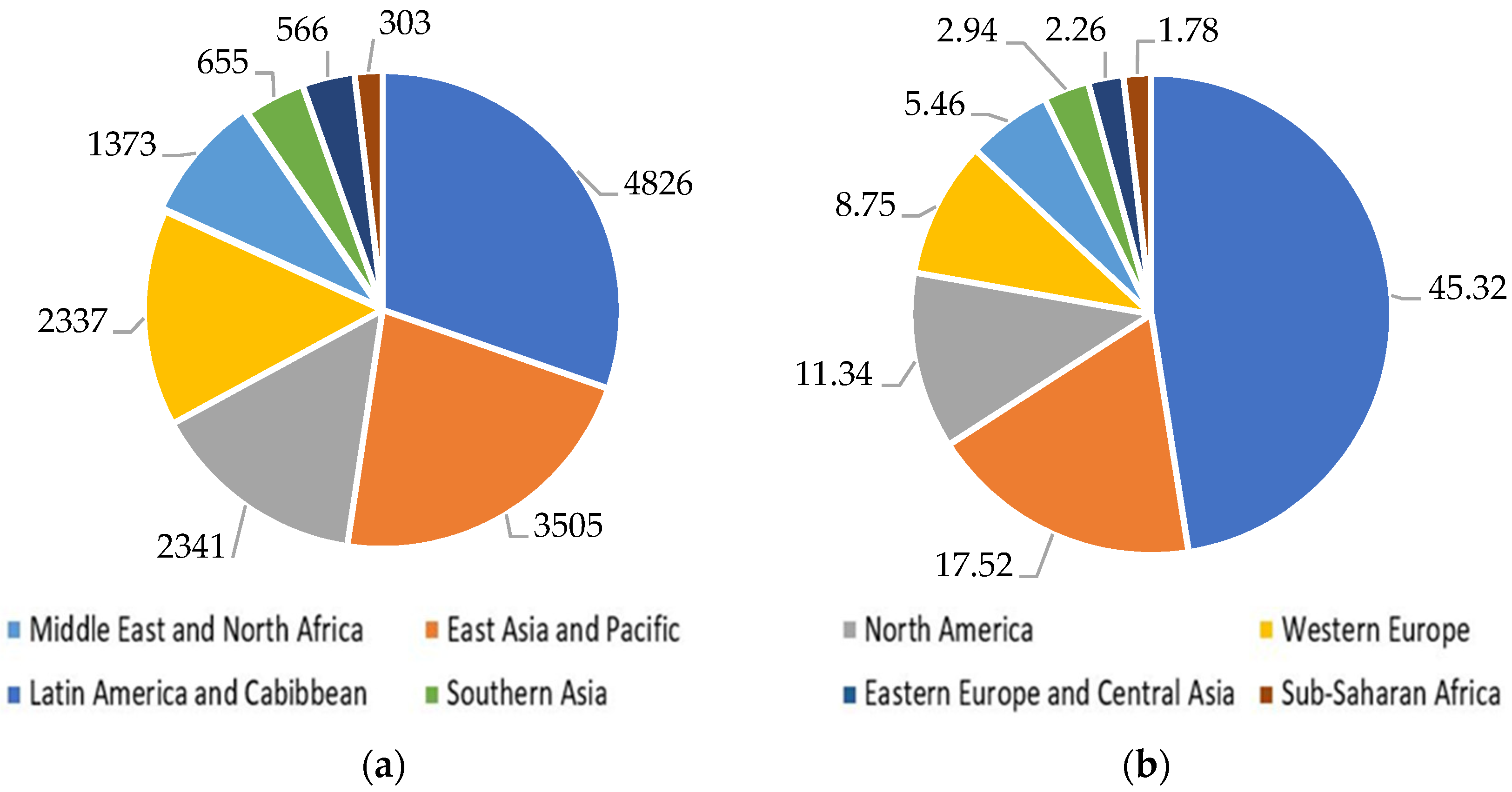
Figure 1. Number and capacity of desalination plants by region in 2019: (a) number of desalination plants; (b) desalination capacity (million m3/day), with data from [9].
Water 13 03023 g001
Figure 2. Schematic diagram of MED, amended from [34].
Water 13 03023 g002
Figure 3. Schematic diagram of MSF, amended from [34].
Water 13 03023 g003
Figure 4. Desalination technology distribution in 2019: (a) desalination capacity (million m3/day); (b) desalination capacity (%), data from [37].
Water 13 03023 g004
Figure 5. Schematic diagram of an RO desalination unit with an energy recovery system, amended from [47].
Water 13 03023 g005
Figure 6. Desalination techniques fed by renewable energy sources in 2017, data from [50].
Water 13 03023 g006
Figure 7. Flow chart of the desalination process, amended from [57].
Water 13 03023 g007
Figure 8. Scheme of the IMPACT 2002+ framework, emission from [59].
Water 13 03023 g008
Figure 9. Scheme of the ReCiPe 2016 framework, emission from [63].
Water 13 03023 g009
Figure 10. CAPEX cost of desalination plants: (a) thermal plants; (b) RO plants [8].
Water 13 03023 g010
Figure 11. OPEX cost of desalination plants: (a) thermal plants; (b) RO plants [8].
Water 13 03023 g011
Figure 12. Human health damage of desalination technologies.
Water 13 03023 g012
Figure 13. Comparison of desalination technologies used with different energy sources with the human health category based on the ReCiPe 2016 method.
Water 13 03023 g013
Figure 14. Comparison of desalination technologies used with different energy sources with the human health category based on the IMPACT 2002+ method.
Water 13 03023 g014
Figure 15. MCDA results of the PESTLE factors with TOPSIS score—the higher, the better.
Water 13 03023 g015
Figure 16. Final results of the MCDA. TOPSIS score: the higher, the better.
Water 13 03023 g016
Table 1. Required energy use of distinct water sources for 1 m3 of drinking water [30,31].
Water Supply AlternativeEnergy (kWh/m3)
Conventional treatment of surface water0.20–0.40
Groundwater0.48
Wastewater treatment0.62–0.87
Wastewater reuse1.00–2.50
Brackish water desalination1.00–1.50
Seawater desalination2.58–8.50
Table 2. Overview of desalination technologies [32].
ClassificationThermalMembrane
Desalination technologiesMED, MSF, MVC, TVCMF, UF, NF, MB, MD, ED, RO
Separation mechanismPhase changeDiffusion
Main type of energy requirementsThermalElectricity
Driving forceHeatPressure/Electricity
Specific energy consumptionHighLow
Table 3. Comparison of desalination techniques [49,50,51,52].
Thermal TechnologyMembrane Technology
MSFMEDMVCTVCEDRO
Water typeSeawater, BrackishSeawater, BrackishSeawater, BrackishSeawater, BrackishBrackishSeawater, Brackish
Operation temperature (°C)90–1107070–10063–70AmbientAmbient
Typical unit size (m3/day)50,000–70,0005000–15,000100–300010,000–30,0002–145,00024,000
Electrical energy consumption (kWh/m3)4–61.5–2.57–121.8–1.62.6–5.55–9
Thermal energy consumption (KJ/kg)190–390230–390none145–390nonenone
Electrical equivalent for thermal energy (kWh/m3)9.5–19.55–8.5none9.5–25.5nonenone
Total electric equivalent (kWh/m3)13.5–25.56.5–117–1211–282.6–5.55–9
Maximum value of CO2 emissions (kg CO2/m3)2419.211.5215.38.6
Distillate quality—TDS (ppm)~10~10~10~10150–500<500
Unit product cost (USD/m3)0.52–1.750.52–1.012–2.60.8270.6–1.050.52–0.56
Table 4. Energy consumption and water production cost of renewable energy (RE) desalination [52].
RE Desalination ProcessTypical Capacity
(m3/day)
Energy Demand
(kWhe/m3)
Water Production Cost
(USD/m3)
Solar still<100Solar passive1.3–6.5
Solar MEH1–100Thermal 29.6
Electrical 1.5
2.6–6.5
Solar MD0.15–1045–5910.5–19.5
Solar pond/MED20,000–200,000Thermal 12.4–24.1
Electrical 2–3
0.71–0.89
Solar pond/RO20,000–200,000Seawater 4–6
Brackish water 1.5–4
0.66–0.77
Solar CSP/MED>5000Thermal 12.4–24.1
Electrical 2–3
2.4–2.8
Solar PV/RO<100Seawater 4–6
Brackish water 1.5–4
11.7–15.6
6.5–9.1
Solar PV/EDR<1001.5–410.4–11.7
Wind/RO50–2000Seawater 4–6
Brackish water 1.5–4
6.6–9 small capacity
1.95–5.2 for 1000 m3/d
Wind/MVC<1007–125.2–7.8
Geothermal/MED80Thermal 12.4–24.1
Electrical 2–3
2–2.8
Table 5. Typical desalination plant inventory data for the production of 1 m3 of drinking water [58].
MSFMEDROUnit
InputSeawater1093m3
Heat Energy290267.5-MJ
Electric Energy424kWh
DisinfectantChlorine20.518.53.5g
AntiscalantPhosphoric acid-276g
Sulfuric acid20-195g
Chlorine removalSodium bisulfite-189g
AntifoamPropylene glycol10.9-g
CoagulantAluminum chloride--6.75g
Ferric chloride--53.7g
FlocculantPolyacrylamide--6.3g
Mineral supplementationCalcium hydroxide0.50.50.5g
OutputChlorine0.70.70.7g
Phosphoric acid-10-g
Sulfuric acid8-6g
Copper (from corrosion of structural materials)0.0320-mg
Propylene glycol0.090.09-g
Sodium chloride454545kg
Waste heat73.44114.24-MJ
Table 6. Normalization factors for the four damage categories for Western Europe version 1.0 [59].
Damage CategoriesNormalization FactorsUnit
Human health0.0077DALY/person/year
Ecosystem quality4650PDF*m2*year/person/year
Climate change9950kg CO2/person/year
Resources152,000MJ/person/year
Table 7. Results for the human health category for the three technologies based on the ReCiPe 2016 and IMPACT 2002+ methods.
MethodROMSFMEDUnit
IMPACT 2002+2.98 × 10−61.43 × 10−59.86 × 10⁻⁶DALY
ReCiPe 2016 9.05 × 10−63.89 × 10−53.35 × 10⁻⁵DALY
Table 8. Summary of impact assessment results for the human health category for the three technologies used with different energy sources based on the ReCiPe 2016 method.
Basic CaseNatural GasNuclear
Energy
Solar EnergyWind Energy,
Onshore
Wind Energy,
Offshore
Unit
MSF3.87 × 10−52.00 × 10−51.10 × 10−69.89 × 10−71.10 × 10−71.23 × 10⁻⁷DALY
MED3.24 × 10−51.51 × 10−51.09 × 10−61.05 × 10−62.46 × 10−72.35 × 10⁻⁷DALY
RO8.66 × 10−606.82 × 10−75.58 × 10−75.59 × 10−75.59 × 10−7DALY
Table 9. Summary of impact assessment results for the human health category for the three technologies used with different energy sources based on the IMPACT 2002+ method.
Basic CaseNatural GasNuclear
Energy
Solar EnergyWind Energy,
Onshore
Wind Energy,
Offshore
Unit
MSF1.13 × 10−54.80 × 10−66.62 × 10−75.03 × 10−75.01 × 10−85.26 × 10⁻⁸DALY
MED9.94 × 10−63.38 × 10−66.41 × 10−75.26 × 10−71.11 × 10−71.08 × 10⁻⁷DALY
RO2.86 × 10−603.21 × 10−72.44 × 10−72.45 × 10−72.44 × 10−7DALY
Table 10. Summary of impact assessment results for the three technologies based on the IMPACT 2002+, ReCiPe 2016, and IPCC 2013 methods.
MethodDamage/Impact CategoryUnitROMSFMED
IMPACT 2002+Ecosystem qualityPDF*m2*yr 10.2280.8160.706
Climate changekg CO2 eq4.17416.12313.196
ResourcesMJ primary67.289228.518184.145
ReCiPe 2016EcosystemsSpecies*yr1.88 × 10−88.77 × 10−87.37 × 10−8
ResourcesUSD20130.6102.2041.788
IPCC 2013IPCC GWP 100akg CO2 eq4.27916.37113.387
1 Asterisk “*” means a multiplication operator.
Table 11. Summary of impact assessment results for RO used with different energy sources.
MethodDamage CategoryUnitBasic CaseNuclear
Energy
Solar
Energy
Wind
Energy,
Onshore
Wind
Energy,
Offshore
IMPACT 2002+Ecosystem qualityPDF*m2*yr 10.2280.0720.0630.0630.063
Climate changekg CO2 eq4.1740.1720.1370.1380.138
ResourcesMJ primary67.28956.3942.9522.9672.962
ReCiPe 2016EcosystemsSpecies*yr1.88 × 10−81.31 × 10−99.96 × 10−109.99 × 10−109.98 × 10⁻¹⁰
ResourcesUSD20130.6100.0220.0190.0190.019
IPCC 2013IPCC GWP 100akg CO2 eq4.2790.1850.1490.1490.149
1 Asterisk “*” means a multiplication operator.
Table 12. Summary of impact assessment results for MSF used with different energy sources.
MethodDamage CategoryUnitBasic CaseNatural GasNuclear
Energy
Solar
Energy
Wind
Energy,
Onshore
Wind
Energy, Offshore
IMPACT 2002+Ecosystem qualityPDF*m2*yr 10.8160.2360.1950.0220.0040.004
Climate changekg CO2 eq16.12313.7780.7670.3790.0350.045
ResourcesMJ primary228.518248.7921129.4945.4720.7420.858
ReCiPe 2016EcosystemsSpecies*yr8.77 × 10−85.12 × 10−86.86 × 10−91.70 × 10−92.04 × 10−102.37 × 10⁻¹⁰
ResourcesUSD20132.2042.0350.0640.0180.0050.006
IPCC 2013IPCC GWP 100akg CO2 eq16.37114.6140.8010.4090.0380.048
1 Asterisk “*” means a multiplication operator.
Table 13. Summary of impact assessment results for MED used with different energy sources.
MethodDamage CategoryUnitBasic CaseNatural GasNuclear EnergySolar
Energy
Wind
Energy, Onshore
Wind
Energy, Offshore
IMPACT 2002+Ecosystem qualityPDF*m2*yr 10.7060.1710.1990.0420.0260.026
Climate changekg CO2 eq13.19611.0340.7220.3790.0710.062
ResourcesMJ primary184.145202.8471020.4315.5811.3191.214
ReCiPe 2016EcosystemsSpecies*yr7.37 × 10−84.00 × 10−86.51 × 10−91.87 × 10−95.23 × 10−104.92 × 10⁻¹⁰
ResourcesUSD20131.7881.6320.0620.0210.0090.008
IPCC 2013IPCC GWP 100akg CO2 eq13.38711.7670.7550.4080.0750.066
1 Asterisk “ * “ means a multiplication operator.
Table 14. Summary of impact assessment results, with the weighting as a single score, using the IMPACT 2002+ method.
Damage CategoryUnitROMSFMED
Human healthmPt0.4031.6001.330
Ecosystem qualitymPt0.0170.0600.052
Climate changemPt0.4221.6301.330
ResourcesmPt0.4431.5001.210
TotalmPt1.2804.7903.920
Table 15. The alternative ratings for the qualitative criterion in the case of the classical TOPSIS method. 1—poor; 3—medium poor; 5—fair; 7—medium good; 9—good; 2, 4, 6, 8—intermediate values in between.
PESTLE CategoryROMSFMED
Political and legal777
Technological977
Economic957
Table 16. The scale of criterion weights in the TOPSIS method. 0.005—very very low (VVL); 0.125—very low (VL); 0.175—low (L); 0.225—medium low (ML); 0.275—medium (M); 0.325—medium high (MH); 0.375—high (H); 0.425—very high (VH); 0.475—very very high (VVH).
Political and LegalSocialTechnologicalEconomicEnvironmental
ScaleVVL-VLMHVVL-VLLH
Weight0.06250.3250.06250.1750.375
Publisher’s Note: MDPI stays neutral with regard to jurisdictional claims in published maps and institutional affiliations.