Article

Performance of Closed Loop Venturi Aspirated Aeration System: Experimental Study and Numerical Analysis with Discrete Bubble Model

Department of Mechanical Engineering, The University of Alabama, Tuscaloosa, AL 35487, USA
*
Author to whom correspondence should be addressed.
Water 2020, 12(6), 1637; https://doi.org/10.3390/w12061637
Submission received: 29 April 2020 / Revised: 5 June 2020 / Accepted: 5 June 2020 / Published: 7 June 2020
(This article belongs to the Section Wastewater Treatment and Reuse)

Abstract

:
In wastewater treatment plants, aeration plays a significant role as it encourages aerobic respiration of microbes, which are necessary to break down carbonaceous matter in the waste stream. This process can account for the majority of energy use in wastewater treatment plants. The aeration process is also necessary in odor control in lagoons and in the aquaculture industry. Generally, the aeration process is accomplished with compressors or blowers which can be of low efficiency due to ideal gas laws. This study introduces the idea of increasing aeration efficiency by looping water from a reservoir through a piping network which includes a venturi aspirator at its inlet. For this purpose, an experimental study has been conducted in a laboratory setup with a pump which pulls water from a tank, passes it through a Venturi aspirator and a helical piping network intended to increase bubble residence time, before depositing it back into the bulk fluid tank. This same process is modeled computationally, using a discrete bubble method (DBM), with good agreement with experiments. The overall purpose here is to determine the optimal configurations for standard aeration efficiency (SAE) and the standard oxygen transfer rate (SOTR). A parametric study has been implemented using the DBM based on different hydraulic and flow parameters. The model is also used to predict the SAE of a hypothetical aeration system. Results indicate that it is possible to achieve SAE values in the range of surface aerators or submersed jet aerators using the proposed aeration system with less complex components, thereby decreasing overall costs.

1. Introduction

The ecological quality of a water system depends on the availability of the dissolved oxygen (DO) in the system. Although water molecules contain an oxygen atom, this is not readily available to cellular life for respiration. In fact, it is a measure of the amount of diatomic oxygen (O2) freely available in the water. Therefore, the dissolved oxygen level in the water is an important indicator of water quality as aquatic organisms and fish live on the dissolved oxygen in the water. If the dissolved oxygen level is too low, the aquatic life may not survive and the system may have odor problems as well. Additionally, excessive dissolved nitrogen can be harmful to fish and zooplankton. Naturally, oxygen enters the stream from the atmosphere where groundwater discharges into the stream. Therefore, rapidly moving water contains more dissolved oxygen than stagnant water. Bacteria in water depending on this dissolved oxygen consume organic matter. As the DO level decreases due to temperature variation throughout the day or in different seasonal periods, the organic matter can grow to excessive levels and create undesirable bacterial growth. Entraining air bubbles can help oxygen enter the water. As a result, many physical processes have been used in industrial and environmental water streams to aerate liquid by the entrainment of air bubbles.
Water aeration is commonly being use to improve DO concentration in lakes and rivers and to increase water quality [1,2]. Aeration is the process of adding air into a water stream in the form of small bubbles and allowing them to rise through the water column. The efficiency of aeration depends on the amount of surface contact between the air and water which is controlled mainly by the size of the air bubble. Aeration helps increase the dissolved oxygen level when there is a deficiency in the system. Different hydraulic structures can be introduced to improve dissolved oxygen levels by creating turbulent conditions where small air bubbles are carried into the water stream. It has been stated [3] that about 4% of national energy consumption is consumed by wastewater treatment plants. Energy used in aeration processes in wastewater plants amount to over 60% of total energy consumption of the overall plant [4].
Many different types of aerators are used for a variety of diverse needs and processes. Fine pore aerator systems are today most often available in municipal wastewater aeration in developed countries, due to their advantageous aeration efficiency (mass of oxygen transferred per unit of energy required). This type of aeration device is placed at the bottom of aeration tanks/ponds with limiting water depths of 13 to 16 feet. To overcome this high water column pressure, high energy compressed air is injected through the pores which translates into high energy consumption and higher costs. Fine-pore diffusers have two major disadvantages: (a) clogging if not cleaned regularly; (b) decrease in oxygen transfer efficiency caused by dissolved surfactants.
Other water aeration devices are surface aerators or coarse bubble generators. Older water treatment plants and many industrial treatment plants are still equipped with these motor-driven propellers or surface aerators. These surface aerators require larger motors in the range of 25 hp–300 hp to operate and facilities may utilize multiple aerators simultaneously. They aerate water by agitating surface wastewater in order to infuse oxygen. Higher energy consumption of surface aerators makes them less attractive. Moreover, they have many moving parts which require significant downtime of the plant and maintenance costs [5,6].
The venturi tube has widely been used in measuring flow rate in pipelines, pressurization systems in internal combustion engines, in natural gas transmission, industrial waste gas cleaning, and in dust cleaning [7,8]. Lately, venturi aeration has received increasing attention, and can be regarded as an effective technique to increase air entrainment and oxygen content in water bodies for hydraulic and environmental engineering. In the venturi aeration process, the gas is introduced in the fluid stream when a minimal amount of differential pressure exists between the inlet and the outlet sides of the venturi tube; a vacuum (air suction) occurs at suction holes (throat) of the venturi tube. However, it is also possible to apply a forced gas supply through the throat which limits the gas dispersion efficiency at high gas flow rates [9]. Venturi-type bubble generators have several advantages: (a) simple structure, (b) easy to install, (c) no internal moving parts, and (d) less maintenance. They require less power than competing technologies, which make them a more attractive economic alternative for enhancing gas–liquid mass transfer [10,11]. By using a venturi tube as an aeration device, it is possible to increase the concentration of dissolved oxygen in the water to promote the growth of aquatic life and plants. Venturi aeration systems have recently been applied to fish farming [12] and to agriculture production [13,14]. Since venturi aerators are able to produce large number of fine bubbles, they can have a significant impact in waste water treatment plants as well [15,16].
Aeration efficiency is defined as the ratio of the amount of oxygen transfer to the power consumed. The effectiveness of any aeration system is measured by this parameter. Recently, studies on conduit flow aeration efficiency have been performed [17] considering gate Froude number, gate opening, and conduit length. Bunea [18] investigates bubble column standard aeration efficiency using a metal perforated plate aerator and tries to optimize based arrangement aerator apertures and aperture diameters. There have been several studies performed by Baylar [19,20,21] investigating aeration efficiency of venturi tube flow considering the effect of the Reynolds number, air inlet diameter, location of the air inlet, air injection rates, and the angle of the Venturi tube.
The goal of this study is to explore the effect of different parameters in venturi aeration systems to find an optimized system that will have higher standard aeration efficiency (SAE). An analytical model is developed based on the discrete bubble model premise. One of the objectives of this study is to investigate whether this analytical model can be applied to model the oxygen transfer for an accompanying experiment. With model validation, the DBM technique is then used to determine the effects of pipe diameter, pipe length and number of aerators on resulting SAE. This paper is completely unique in that it is the first study conducted to consider the possibility of an accompanying “closed loop tube” to increase bubble residence time and hence, aeration efficiency, when compared to other venturi aeration systems.

2. Clean Water Tests

To compare different aeration systems and configurations, the clean water testing procedure described in ASCE 2007 [22] is followed. This reference describes the procedure to calculate the standard oxygen transfer efficiency (SOTE, %), the standard oxygen transfer rate (SOTR, kgO2/h), and the standard aeration efficiency (SAE, kgO2/kWh). To calculate the SAE, the power measurement is important and can be expressed in different ways. Generally, power measured directly from the electrical cabinet is usually desirable as it includes blower, coupling, gearbox, and motor inefficiencies. To measure SAE, the standard conditions are 20 °C temperature, zero DO, mean atmospheric pressure, and zero impact of water salinity or other contaminants (e.g., α factor = 1.0, β factor = 1.0). Clean water test results can be used as a warranty of performance between different systems.

3. Experimental Procedure

Before starting each experiment (see Figure 1), a large aeration tank was filled with water. The aeration tank maximum capacity is 300 gallons. The height of the tank is 6.75 ft with 2.92 ft in diameter. The tank is filled with 250 gallons of tap water and the height of the water level from the bottom of the tank is approximately 5 ft. In industrial boiler systems, it is very common to use anhydrous sodium sulfite (Na2SO3) in the presence of a catalyst (CoCl2) to scavenge DO in water [23]. Sodium Sulfite ( N a 2 S O 3 ) was added to the water which produced Sodium Sulfate N a 2 S O 4 . The following Equation shows the chemical reaction achieving oxygen scavenging:
2 N a 2 S O 3 + O 2 2 N a 2 S O 4 ,
According to Equation (1), the amount of Na2SO3 required can be determined by knowing the water volume in the system, the present DO concentration, and the required level of DO concentration. CoCl2 was used to increase the reaction speed and the suggested amount was 0.1% of Na2SO3 by weight [23,24]. Theoretically, 7.88 mg/L of Sodium Sulfite is required to scavenge 1 mg/L of dissolved oxygenation concentrations.
The aeration system testing has two steps: (1) deoxygenate the testing water and then (2) reaerate the water while recording the DO concentration. For this purpose, two Vernier optical DO probes (Model Number: ODO-BTA) are used to measure the instantaneous dissolved oxygen concentrations in the aeration tank at two suspended heights. The Vernier DO probe comes with its own data acquisition system where data are collected at a frequency of 1 Hz. The DO probe has the capability of self-calibration based on atmospheric pressure and temperature.
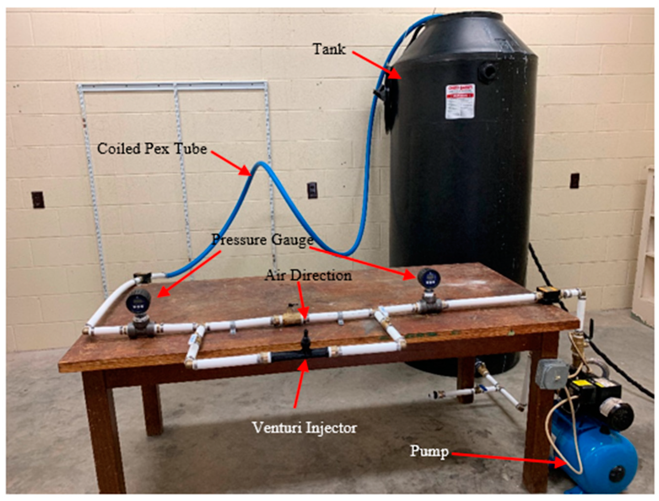
A small scale experimental system was built to see the performance of the venturi injectors with a coiled pipe of varied lengths. The system is shown in Figure 2. The list of equipment required to do the test is listed in Table 1. The setup with a single venturi injector is shown in Figure 1. The list of equipment required to do the test is listed in Table 1.
The pumps and aeration tanks are on at floor level in the aeration testing lab of The University of Alabama. During tests, the aeration tank is closed and therefore, surface oxygen enrichment is neglected. The system creates a positive pressure head in the pump’s suction side. The pump is self-priming and has its own six-gallon pressurized tank attached to it. The suction side water flow rate is controlled with a ball valve. The discharge side of the pump is attached to the flowmeter and pressure gauge to measure the flow rate and pressure in the discharge side of the pump. Instead of adding the venturi injector directly to the main line, it has been added to the side line and whenever the operation venturi injector is required, the mainline valve is shut and the side line valve is opened. From the discharge side of the injector, the coiled, cross-linked polyethylene (PEX) pipe is attached. Since the PEX pipe is coiled and can be kept hanging over the wall with a mounting, it does not hold much space and the length of the coiled pipe is also variable. Finally, the coiled pipe discharges over the aeration tank, making the outlet thermodynamic pressure to be atmospheric pressure. The pressurized water, when traveling through the convergence part of the injector, experiences a pressure drop to below atmospheric pressure due to the venture effect in the throat, which results in the suction of air through the venturi suction port and a large number of small air bubbles are produced. The suction diameter of the venturi injector is 0.75 inches.
Three individual tests have been conducted with the experimental setup shown in Figure 2. In the first two experiments, the pressure differential between the injector inlet to the outlet is varied from 6.6 psi to 12.4 psi. In the last experiment, the flow rate of the moving fluid was varied with a ball valve from 1.26 cfm to 1.13 cfm along with a reduction in the injector inlet pressure. In all experiments, two oxygen probes are used in different depths of the tank to observe the dissolved oxygen level. The oxygen probes are able to collect one sample of data per second. The variation of dissolved oxygen data from the two probes was insignificant, confirming that the water in the aeration tank had been well mixed. Since, in all cases, the pressure differential between the injector inlet and outlet has been varied, the suction air through the injector hole is also different in each case. Table 2 lists the important experimental parameters that varied throughout the tests.

4. Theory

This section provides an overview of the theory that is being used in calculating aeration efficiency for the experimental setup. Moreover, this section discusses the fundamentals behind the discrete bubble modeling and the algorithm developed for numerical analysis.

4.1. Two Film Theory

Mass transfer in multiphase flow (gas–liquid–solid) processes is a significant phenomenon occurring in chemical, petrochemical, and biological engineering problems. The transport of species among phases is accomplished by two means: diffusion (physical) and chemical reactions. There are several parameters that govern this mass transfer process, for example, system pressure, temperature, concentration gradients, reaction kinetics, conductance of mass transfer, and activation energy.
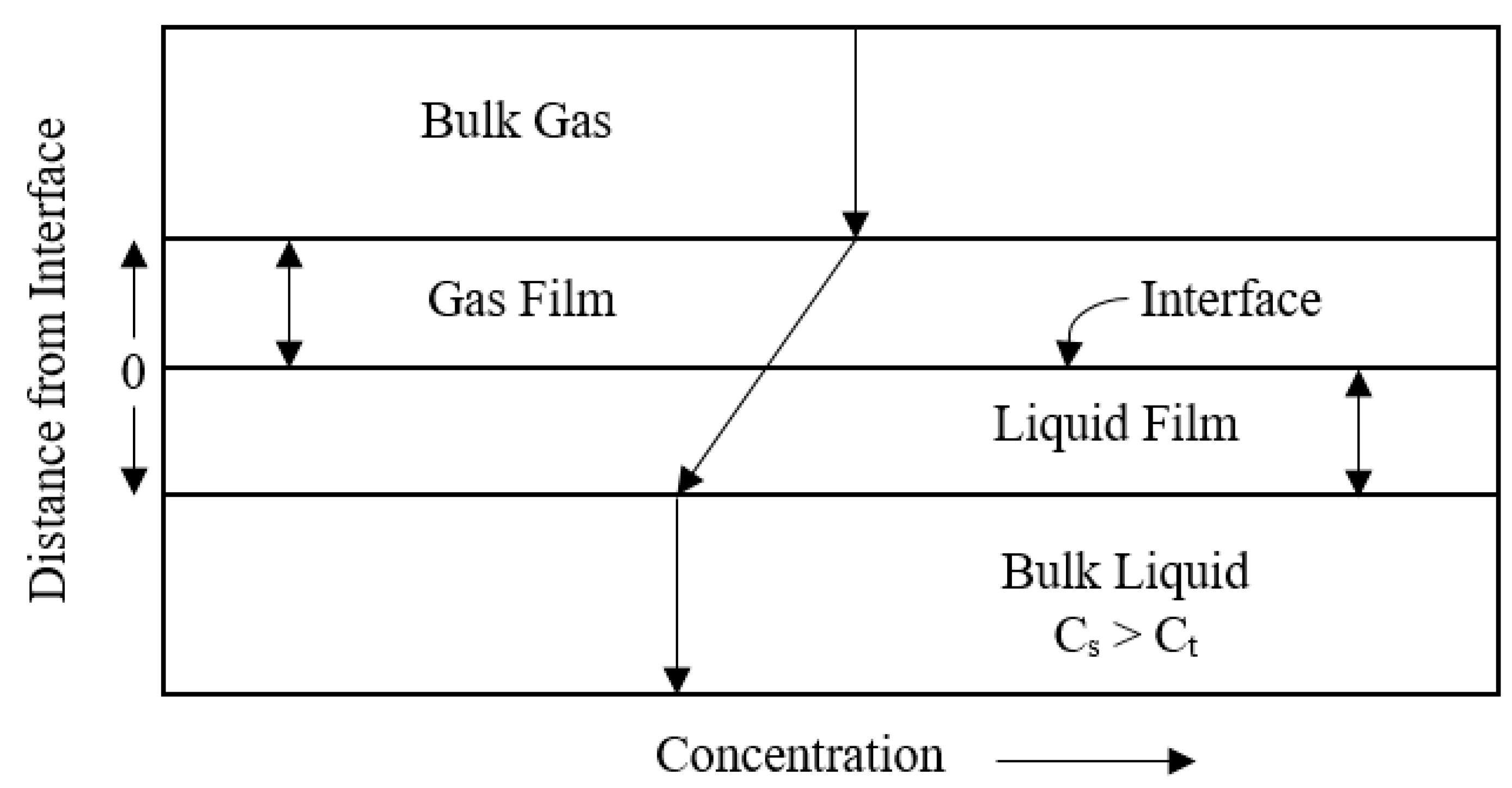
There are different theories available for dealing with mass transfer among the phases, for example, two-film theory, penetration theory, and the surface renewal theory. Among them, the two-film theory developed by Lewis and Whitman [26] is one of the oldest for gas transfer to a particular liquid. The theory assumes that there exists a stagnant gas and a stagnant liquid film with thickness (δ) which are separated by an interface. The thin films are covered by gas bulk and liquid bulk on their respective sides. To dissolve a gas molecule into the liquid, it has to pass these four distinct regions. The reversed path applies for a gas molecule leaving the liquid. The assumptions made in this theory are: (1) linear concentration profile in stagnant films, (2) mass transfer through the films occurs as steady-state conditions, (3) instantaneous equilibrium, and (4) dilute solutions and Henry’s Law is applicable. The theory states that the boundary (or the interface) of gas–liquid phases is two distinct films. Figure 3 shows an illustrative diagram for the two-film theory.

4.2. Experimental Results Evaluation Technique

Bubble aeration is a mass transfer process. The rate of gas transfer is generally proportional to the difference between the existing concentration and the equilibrium concentration of the gas in the solution. This rate of gas transfer is basically governed by the liquid phase mass transfer coefficient, K L . However, it is non-trivial to determine the interfacial area for mass transfer ( A t ) per unit volume (V) experimentally. In that case, the overall mass transfer coefficient K L a is used without obtaining the factors K L and ( A t V ) . In short, the overall mass transfer coefficient is written as follows:
K L a = K L × A t V
In Equation (2), K L a is an overall volumetric oxygen mass transfer coefficient in clean water, h−1, V is water volume in the tank, m3 and A t is an interfacial area of mass transfer, m2. Moreover, a = A t V is interfacial area per unit volume m2/m3. To determine the oxygen transfer coefficient K L a non-steady methods were employed [26]. According to two-film theory and Fick’s law [27,28,29], the non-steady oxygen transfer differential equation is:
d C d t = K L a × ( C s C t )
After integration, Equation (3) becomes,
C t = C s ( C s C 0 ) e K L a t
where, C s is the saturation concentration of oxygen under test conditions, C 0 is the concentration of oxygen at time, t = 0 and C t is oxygen concentration at time t . If the initial concentration in the liquid is C 0 = 0 , then Equation (4) becomes:
C t = C s ( 1 e K L a t )
Finally, the total mass transfer coefficient K L a with respect to the total volume of liquid in the system can be calculated in the following way [30]:
ln ( C S C t ) = K L a × t
Here, K L a is the mass transfer coefficient of the system measured in (h−1) at water temperature T. Applying non-linear regression analysis of the logarithmic function of concentration deficit ( C s C t ) with aeration time t, it is possible to determine K L a . K L a is then converted to a standard reference temperature of 20 °C ( K L a 20 ) followed by Equation (6):
K L a 20 = K L a / θ ( T 20 )
In Equation (7), T represents the water temperature (°C) and θ is the temperature correction factor which stands for 1.024 for pure water. For any aeration system to compare with the existing system, it is very important to discuss the standard oxygen transfer rate (SOTR). The SOTR is defined as the mass of oxygen transferred to the water volume per unit time when zero initial dissolved oxygen and standard conditions are considered (i.e., water temperature at 20 °C and pressure at 1 atm). SOTR is therefore defined as follows:
SOTR = K L a 20 × ( C s C 0 ) × V
The efficiency of the aeration system is determined by computing standard aeration efficiency, which is stated as rate of oxygen transfer per unit power input and expressed in the following way:
SAE = SOTR P i n
In this Equation, P i n stands for the total power drawn from the outlet of the compressor or pump. It is expressed in Kg O2/kWh or lbs O2/hp-h.

4.3. Discrete Bubble Model (Analytical Technique)

The analytical model used here is a discrete bubble model. The discrete bubble model was first used in literature [31] in the phenomena of plug flow through a tank of well-mixed water. Bubbles affect the flow significantly when they are experiencing large pressure gradients and velocity variations. This model tracks every bubble motion as discrete entities and also the bubble deformation due to mass transfer across the bubble surface. The main characteristics of this model are listed below:
  • The model is based on the Euler-Euler (E-E) approach.
  • This model is capable of solving homogeneous multiphase flow.
  • This E-E model employs the volume averaged mass and momentum conservation equation to describe time dependent motion of both phases.
  • The bubble number contained in a computational cell is represented by a volume fraction.
  • The bubble size information is obtained by incorporating population balance equations with break-up and coalesce of bubbles as well as growth or shrinkage of bubbles due to mass transfer across the bubble surface.
This model is being extensively used in modeling gas–liquid dispersed flow in bubble column reactors to investigate complex phenomena like hydrodynamics, mass transfer, and chemical reactions [32,33,34]. The benefit of using the Euler-Euler approach is that the number of bubbles is not limited and storage requirement and computational power demand are not dependent on bubble numbers. However, this approach comes with diffusion errors and is sensitive to bubble diameter. The distribution of bubble diameters is either estimated by population balance along with coalescence and break up events [35] or directly obtained from the experiment [36,37]. DBM is applied successfully in airlift aerators [38,39], bubble plume [40], and diffused bubble and wastewater ozonation systems [41,42]. In this present paper, the bubble and fluid is considered as a continuous interpenetrating fluid which gives the opportunity to use the DBM method to predict the rate of oxygen transfer during bubble aeration. The bubbles are considered spherical in shape, which simplifies the forces exerted on the bubbles. In DBM studies, no turbulence of continuous phase is considered. The specific interface area is significant since the mass transfer among the two phases is dependent on it. In fact, the bubble size distribution is time-dependent, as processes like bubble coalesce and break up affect this phenomenon. Consequently, this affects the interface area and mass transfer. In this study, the size of the bubble is a function of the pressure gradient and mass transfer only, and the effects of bubbles coalescing and breaking up is overlooked.
The bubbles are assumed to be moving with the fluid with an average mixture velocity. For each experiment, the number of bubbles in the pipe at any given time is assumed to be invariable considering that no input of the system has been changed. The bubbles are simply experiencing pressure forces inside the pipe which varies along the pipe length. Surface tension and liquid head pressure is negligible in this case. For simplifying the model, it is assumed that bubble break-up and coalescing are not occurring. The flow is incompressible with the volume-average mixture properties (e.g., viscosity, density) being used. The distribution of the bubble size is represented by a single Sauter mean diameter [43]. The water and air temperature are assumed to be equal and constant. The mass transfer flux across the surface of a bubble is:
J = K L ( C s C )
where, K L is liquid side mass transfer coefficient, C S is equilibrium concentration at the gas/water interface, C is bulk aqueous-phase concentration, and J is mass transfer flux.
The gas side mass transfer resistance has been neglected. The equilibrium concentration can be expressed as:
C s = H P i
where, H is Henry’s constant and P i is partial pressure of the gas.
With this, Equation (10) can be written as follows:
J = K L ( H P i C )
Henry’s constant ( H ) (mol.m−3.bar−1) and mass transfer coefficient (ms−1) are determined in the following way [44]:
H o = 2.125 5.021 × 10 2 T + 5.77 × 10 4 T 2   ( T   i n   ° C )
and
K L = 0.6 r ,   r   <   6.67   ×   10 4   m
K L = 4 × 10 4 ,     r     6.67   ×   10 4   m
The rate of mass transfer across the surface area of the bubble of radius (r) can be obtained from the mass transfer flux Equation:
d m d t = J × A = K L ( H P i C ) × 4 π r 2
The discrete bubble is moving with the water with mixture velocity v m . At any time, the velocity of the bubble inside the pipe along the horizontal axis can be related by the following equation:
d x d t = v m
Since the bulk aqueous-phase concentration does not change significantly during the travel of bubbles inside the pipe, the pseudo-steady state assumption may be considered. From this equation, it is possible to determine the mass transfer of gaseous species per bubble per unit length of pipe:
d m d x = K L ( H P i C ) 4 π r 2 v b
The number of bubbles in the pipe at any instant is constant. This number of bubbles is calculated by knowing the volumetric flow of air through the venturi injector, Q 0 and the initial bubble volume, V 0 .
N = Q 0 V 0
Multiplying the mass transfer equation for a single bubble with the total number of bubbles ( N ) will give the total mass transfer per unit length at per unit time.
d m d x = K L ( H P i C ) 4 π r 2 × N v b
The above equation is a one-dimensional ordinary differential equation. On the right hand side, the variables are H , which is function of temperature only and K L , which is a function of bubble radius.
Bubble radius will change with the change in pressure inside the pipe and also with the mass transfer of oxygen and nitrogen gas across the bubble and liquid interface. As said before, the ideal gas law is used in this case to measure the change of bubble radius with time.
In this experiment, a coiled pipe is used to transfer water from the source to the aeration tank. To include the effect of the coiled pipe in the calculation, the friction loss of this type of pipe is being calculated using the Mishra and Gupta correction factor with Blasius correlations [45]. The friction factor for curved or helically coiled tubes, taking into consideration the equivalent curve radius, R C , is as follows:
f = 0.316 R e 1 4 + 0.0075 D P 2 R C
R C = R [ 1 + ( H 2 π R ) 2 ]
where, D P , R , H , and R e represent pipe diameter, curve radius, helicoidal pitch, and Reynolds Number respectively.
In the current analysis, the two phase flow is modeled as the homogeneous flow model which is the simplest technique for analyzing multiphase flows. In the homogeneous model, both liquid and gas phases move at the same velocity (slip ratio = 1). It is also known as the zero slip model. The homogeneous model considers the two-phase flow as a single-phase flow having the average fluid properties in which the properties depend upon the mixture quality. For this purpose, one parameter which is known as mass quality is defined as follows:
χ = 1 ( Q a i r Q w a t e r )
where, Q w a t e r and Q a i r stand for volumetric flow rate of water (m3/s) and volumetric flow rate of air (m3/s) respectively.
The definition of two phase viscosity ( μ m ) based on the mass averaged value of the reciprocals of the gas viscosity ( μ g ) and liquid viscosity ( μ l ) is defined as follows:
μ m = ( χ μ g + 1 χ μ l ) 1
The mixture density ( ρ m ) also obtained in the mass averaged process of gas density ( ρ g ) and liquid density ( ρ l ) is calculated as follows:
ρ m = ( χ ρ g + 1 χ ρ l ) 1
The velocity and the Reynolds number of the mixture is calculated in the following way:
v m = ( Q a i r + Q w a t e r ) / A p i p e
The Reynolds number of the mixture can be found in this way:
R e m = ρ m v m D p μ m
where, A p i p e is pipe area which is equal to π 4 D p 2 (m2).
Finally, the frictional head loss (hf) across the length of the coiled pipe (l) is calculated by using mixture density, velocity, and Reynolds number which is written as follows:
h f = f ( l D p ) 1 2 ρ m v m 2
Gordiychuk [46] have performed an experiment to calculate the Sauter mean diameter of the bubble ( d 32 ) generated in venturi-type bubble generators. They have derived the relation to determine the Sauter mean diameter as a function of water flow rate, air flow rate, and air inlet diameter. The relation is given in the following way (see Table 2 of [46] for ML-BGS algorithm):
d 32 d i n l e t , ( s u c t i o n ) = 1215.9 × R e w 1.4767 × R e a i r 0.7566 × α 0.5110
In this relation, α stands for air to water fraction. R e w and R e a i r are Reynolds number for water and air respectively. The Reynolds number of air is evaluated based on suction diameter ( d i n l e t , ( s u c t i o n ) ), suction velocity, and air density. On the other hand, for water, Reynolds number is calculated based on pipe diameter, water velocity and water density.
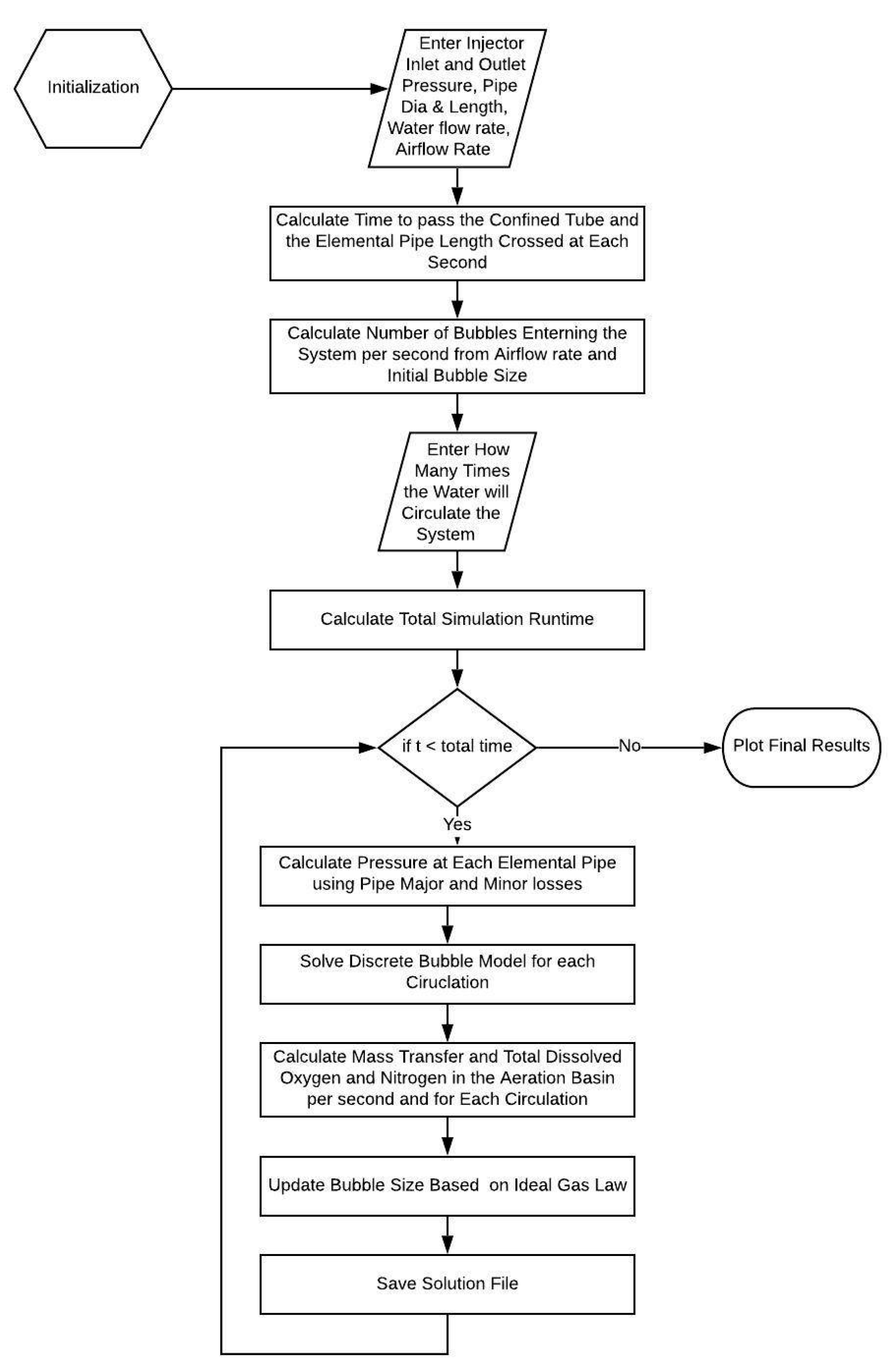
Now that all necessary equations to calculate mass transfer in the discrete bubble model have been documented, an overview of the algorithm structure used for this model is shown in Figure 4:

5. Discussion

In this section, three different experimental results are shown. These results are compared with the results obtained from the discrete bubble model to determine the model efficiency in predicting the oxygen transfer efficiency of the discussed system. In the end, the discrete bubble model is used to predict a proposed aeration system for an aquaculture farm to obtain an SAE over 1.5. The following section is divided in three subsections: the first subsection will validate the analytical model, the second section discusses the effects of different parameters on oxygen transfer efficiency using the discrete bubble model, and the third will cover a proposed aeration system suitable for aquaculture.

5.1. Validation of the Numerical Model

In all experiments, the air suction through the venturi hole was natural. The air suction is dependent on pressure differential and water flow rates for a specific injector. Mazzei documented the air suction rate through the injector hole for different scenarios in their product catalogue for the specific injector model. Since then, the pressure differentials and water flow rate conditions for different experiments in this study are close to what is mentioned in the product catalogue, the air suction rate is not measured but rather is directly used from the catalogue. This also gives the independence of testing different scenarios in numerical studies as it subsides the requirement of measuring suction flow rate. While doing numerical analysis, in each case, the water flow rate is known and the code is also capable of calculating the injector inlet pressure head from different hydraulic parameters. As a result of this, varieties of pressure of differentials can be tested along with different water flow conditions.
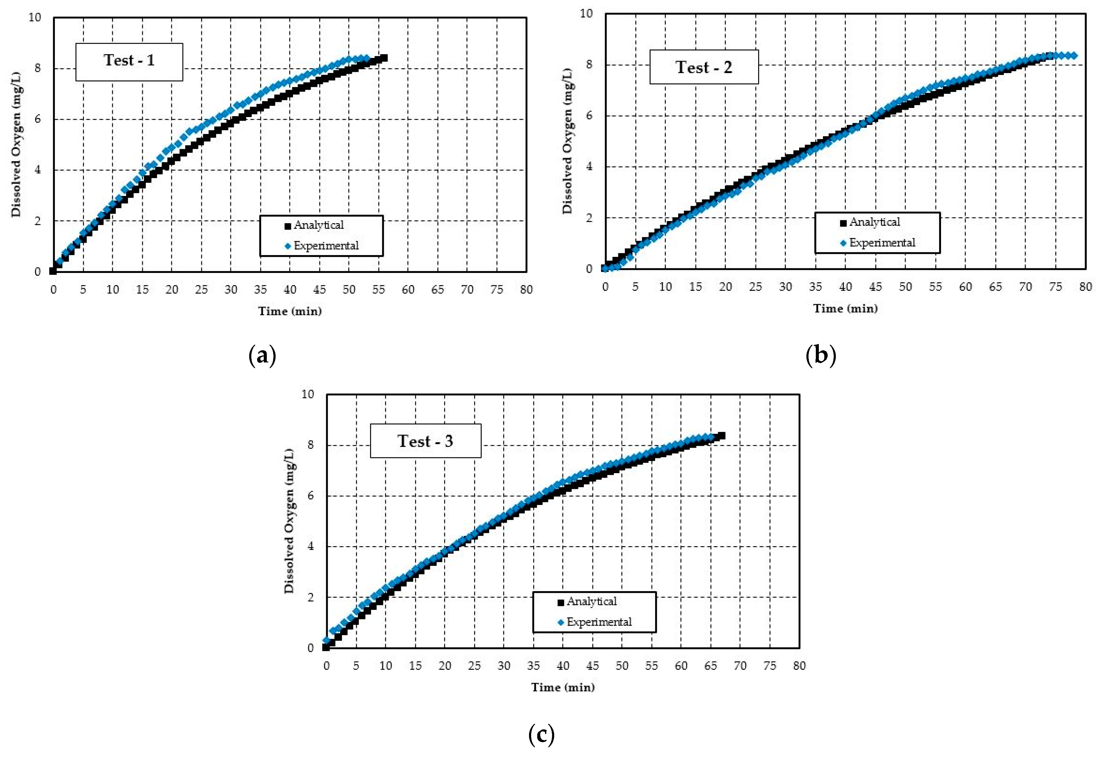
The analytical results were obtained using the same physical parameters as the experiments. Data from the two probes are averaged over the time period. Figure 5 shows the average dissolved oxygen vs. time results for three different experiments. The analytical results obtained through discrete bubble models for each case are plotted in the same graph to show their conformity with the experimental results.
Figure 5 shows the increase in dissolved oxygen in the aeration tank with time. From the experimental results, it can be observed that the first test reaches saturation more quickly than the other two. The second test takes the longest time to reach saturation. This is due to the fact that in the second test, less air is drawn into the aerator. The analytical results are reasonably able to predict the measured DO. In most cases, the analytical model results fall within 10–15% of the measured data, although it underestimates the results. In the beginning of the test, the analytical results divert mostly from the experimental results, but with time the measured and predicted values started to conform more with each other. This difference in predicted results with measured values could happen for several reasons. One of the main factors is the degree of variability of the bubble size in real measurement compared to the analytical model. In the analytical model, all bubbles are considered spherical in shape which is not true in real phenomena. Bubble radius also changes due to coalesce and breakage. Moreover, the effect of turbulent mixing inside the pipe after the injector is not included in the model. The velocity of the bubble and water is assumed to be the same with having a mixture velocity which might be another source of error. This average velocity is added in the model without considering the time-dependent velocity change due to the turbulent flow inside the pipe.
Based on K L a , the standard aeration efficiency (SAE) and the standard oxygen transfer rate (SOTR) are determined. All values of K L a , SOTR and SAE are presented in Table 3 for both the experiment and analytical results. By comparing the experimental results, the highest SAE was achieved for the third test, while the maximum oxygen transfer rate was observed for test-1. This is also valid for the analytical results.
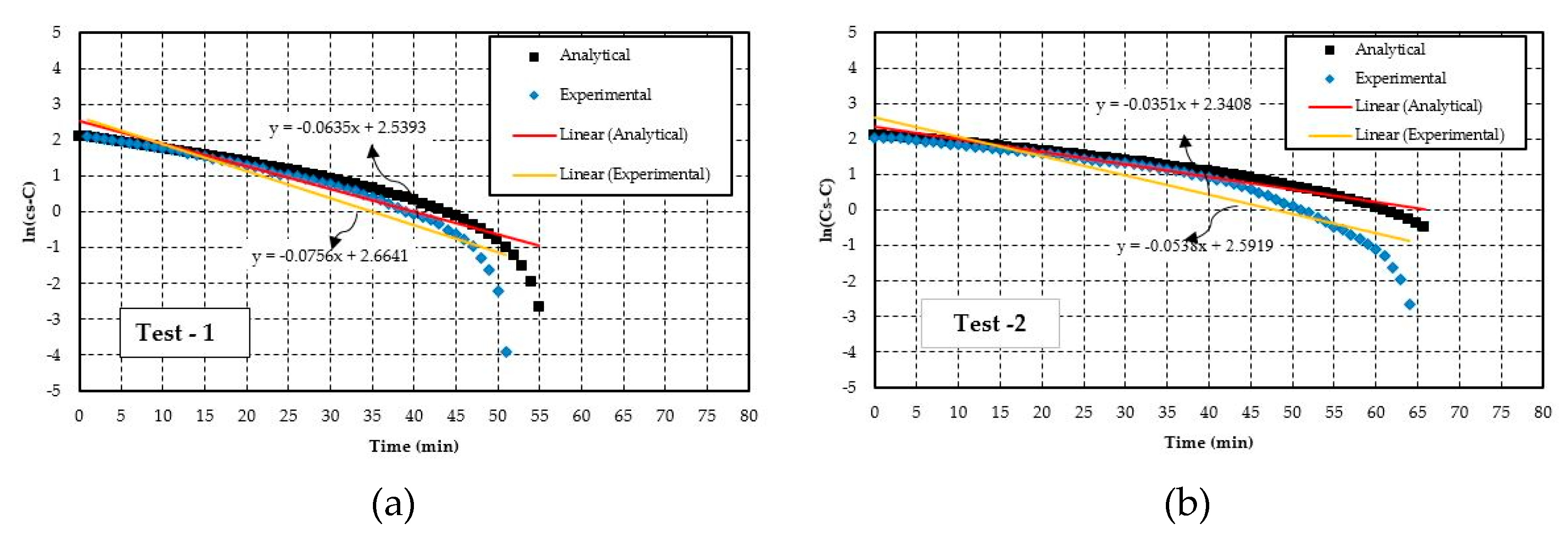
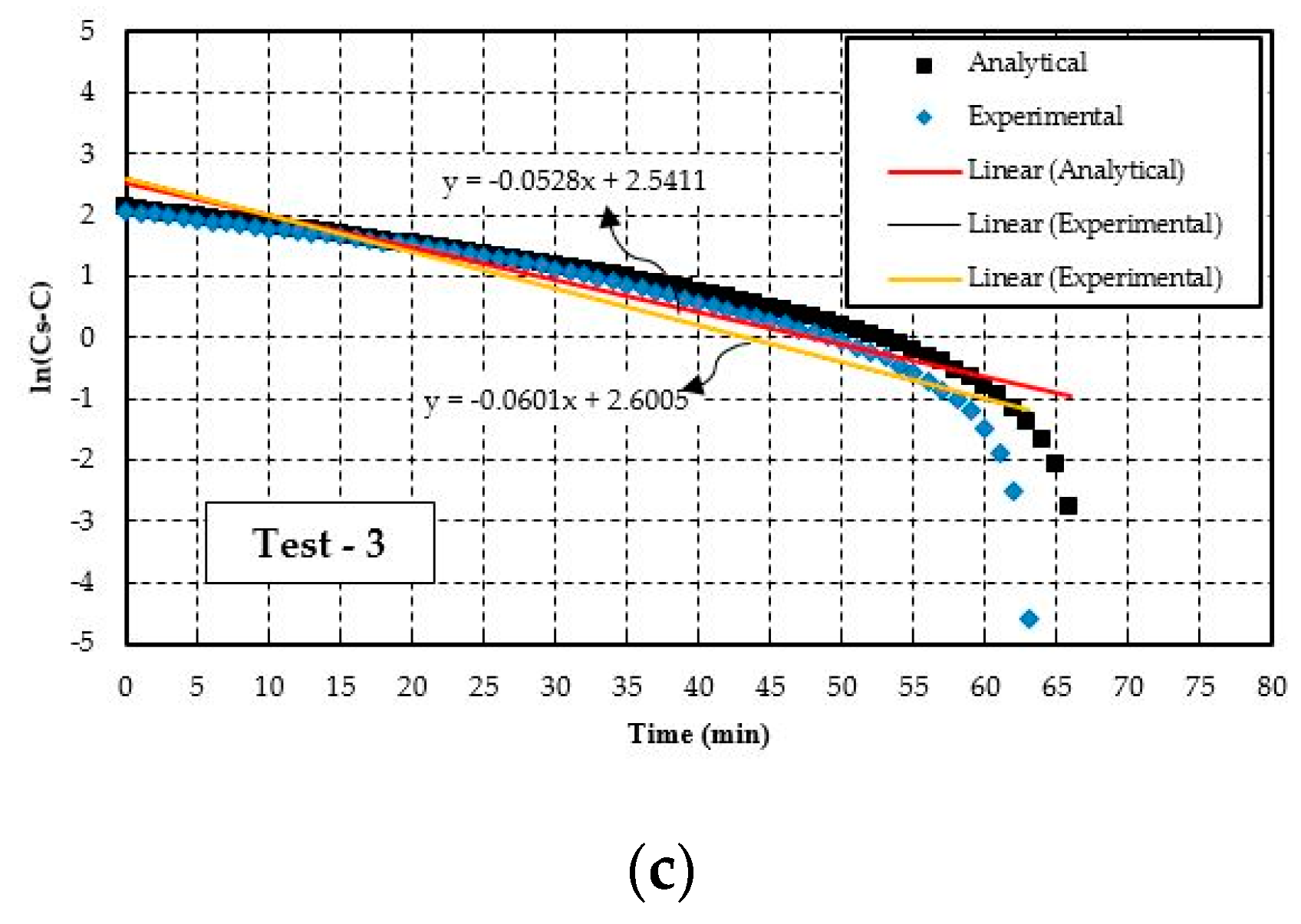
According to Equation (6), a semi log-based graph is plotted with respect to time in Figure 6. The slope of the curve represents the oxygen transfer coefficient ( K L a ) of the aerator module which is an important parameter in determining the efficiency of the aerator. Oxygen transfer coefficient expresses the relationship between the rate of mass transfer and the concentration deficit which is the driving force to dissolve oxygen in the water. In this case, the K L a values obtained through experiment under standard conditions for test-1, test-2, and test-3 are 0.067 min−1, 0.048 min−1, and 0.053 min−1 respectively. The highest oxygen transfer coefficient is achieved through test-1. In the analytical model, a similar log deficit plot is generated to determine the K L a . The analytical model K L a are −0.056 min−1, 0.042 min−1, and 0.047 min−1 for test-1,-2, and -3 respectively. In all cases, the analytical model K L a is less than the experimental K L a values and the difference in them are between 10–16%.

5.2. Parametric Study

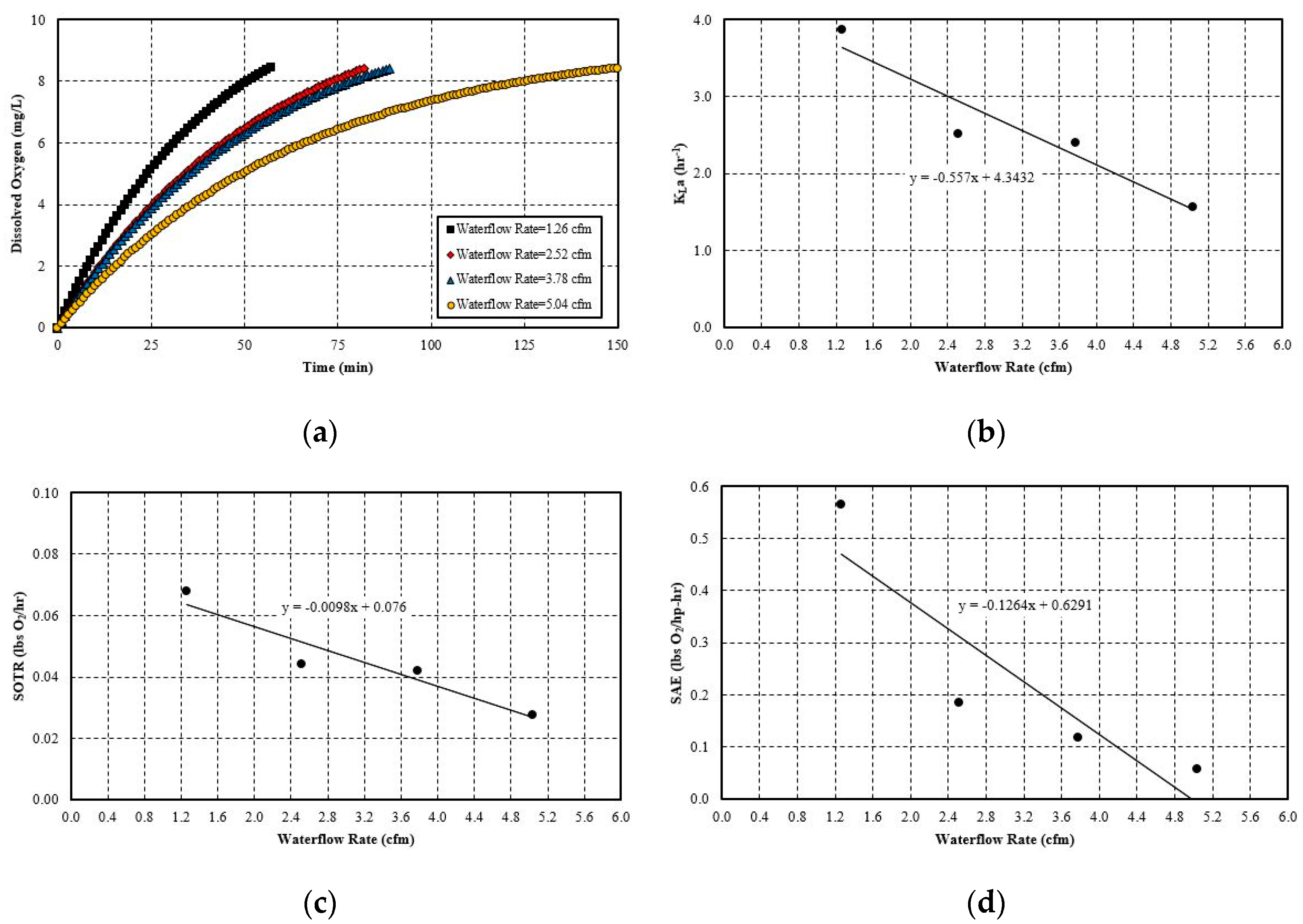
Here, the effects of different hydraulic and flow parameters have been tested with the discrete bubble model. This study gives an insight into which parameters are affecting the oxygen transfer coefficient ( K L a ) , SOTR and SAE, and will help find an optimum input for future, larger-scale systems for aeration purposes. In all cases, test-1 conditions are used while varying test-1 parameters are used to investigate effects on aeration efficiency in varying these parameters.

5.2.1. Effect of Pipe Length

One of the main purposes of this study was to determine the effect of coiled pipe length in oxygen transfer efficiency. The coiled pipe will start after the injector and will hang over the aeration basin. According to [47], in the helical tube, bubbles dispersed mostly around the center of the coil and a drag reduction was observed on the bubble surface. In the analytical model, the same inputs are used from test-1 with only a change in the pipe length.
In Figure 7a, the DO concentration profile versus time is plotted to show the effect of pipe length. The profile conforms to a general non-steady aeration curve where the rate of change in dissolved oxygen levels decrease with time. This is due to a reduction in saturation deficit level with time. It can be observed that, with an increase in pipe length, the system takes less time to reach the saturation level. Since, with an increase in pipe length, bubbles are taking a much longer retention time to transfer oxygen with water, the oxygen transfer rate is also increased. Moreover, the bubbles remain in the center and thus less likely to collide with the pipe surface. This helps them to maintain a spherical shape for a longer period of time and increases the overall mass transfer rate. This mass transfer rate increase comes with a small increase in the friction head loss which causes less pump power rise. In effect, the overall oxygenation transfer efficiency increases. However, this positive effect of pipe length increase dampens after certain intervals (in this case, from 80 ft. to 100 ft.)
K L a , SOTR, and SAE are plotted in the graph from Figure 7b–d with respect to pipe length. In every case, the linear trend line is obtained which passes through most of the values. If the pipe length is doubled, the SOTR is also increased by a factor of 1.4. For a 100 ft. section of pipe, the oxygenation efficiency is 2.6 times better than the 20 ft. pipe. Values of K L a , SOTR, and SAE are listed in Table 4.

5.2.2. Effect of Pipe Diameter

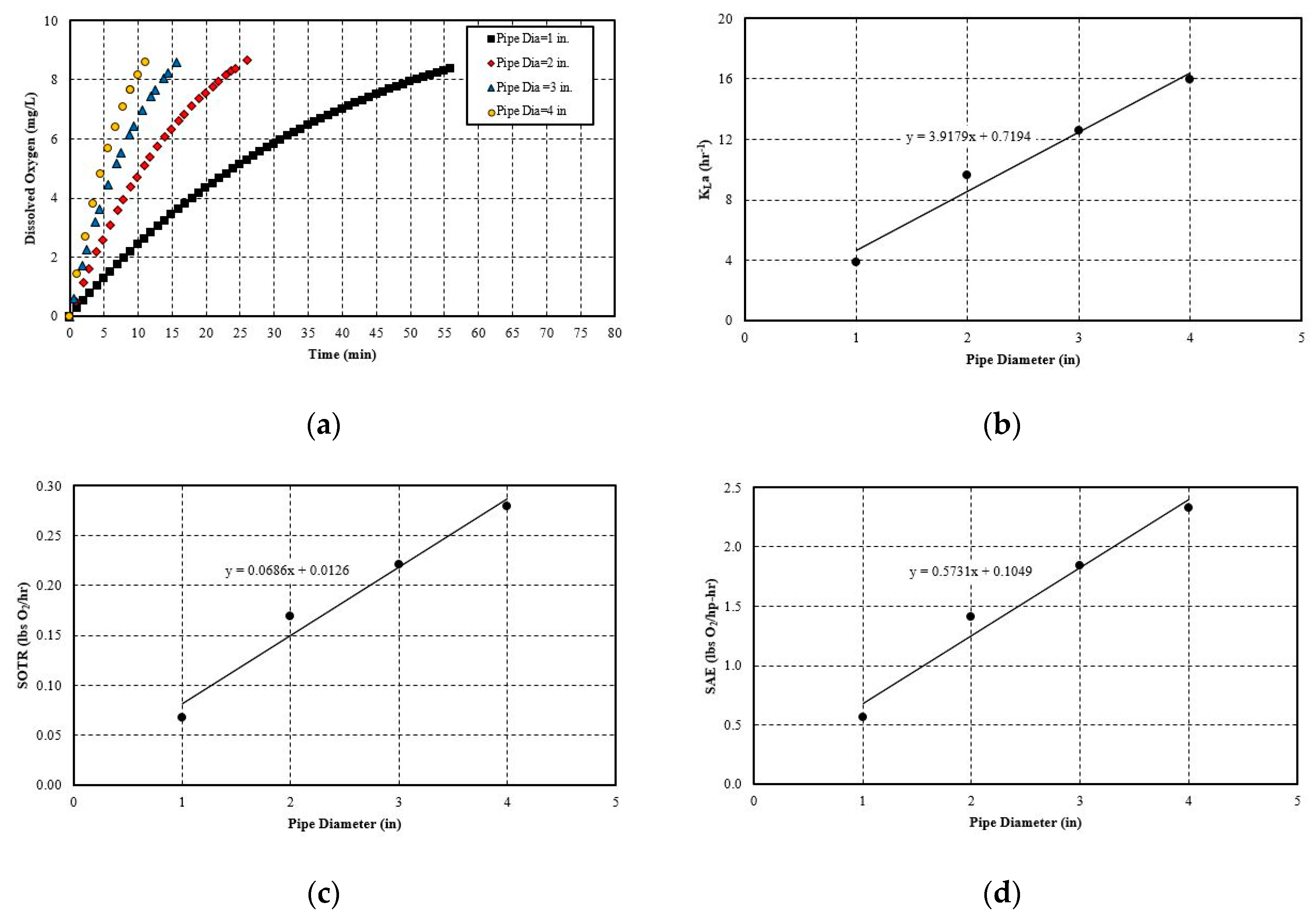
In the current research, only 1-inch diameter pipe is being used for all experiments. However, one-inch pipe usually has a higher frictional loss and thus affects the SAE in a negative way. In Figure 8, effects of diameter change in dissolved oxygen rate and in efficiency are shown.
From Figure 8, it is evident that the dissolved oxygen level rises with time in the aeration tank. The DO level rises rapidly at first, then this rate of increase decreases as it gets close to saturation. It follows that increasing the diameter helps the system reach the saturation more quickly. This can be attributed to the fact that increasing the pipe diameter decreases the mixture velocity. In real phenomena, there exists a slip velocity due to the density difference between two phase flow. The gas bubbles do not exactly travel with the liquid [48]. Additionally, in smaller diameter pipe more bubbles tend to travel towards the pipe wall. Oxygen transfers to the water through diffusion. To overcome the resistance in gas–water interface, bubbles need sufficient time. Since the water velocity decreases with the diameter increase, the gas bubbles get more time for mass transfer to overcome the diffusion resistance. This positive effect can also be observable while determining the oxygenation coefficient as it increases with the diameter increase. In Figure 8b,c, K L a , and are plotted against the diameter and are fitted with a trend line. This trend line equation is a simple mathematical model of the relationship between the diameter with oxygenation coefficient and SOTR. SAE also attains higher values as the system is able to transfer oxygen faster without changing the operating condition of the pump.

5.2.3. Effect of Gas Flow Rate

This section will discuss the effect of increasing the suction gas flow rate while keeping the motive flow rate and the line pressure constant. In this case, the test-1 condition is used only in changing the gas suction rate.
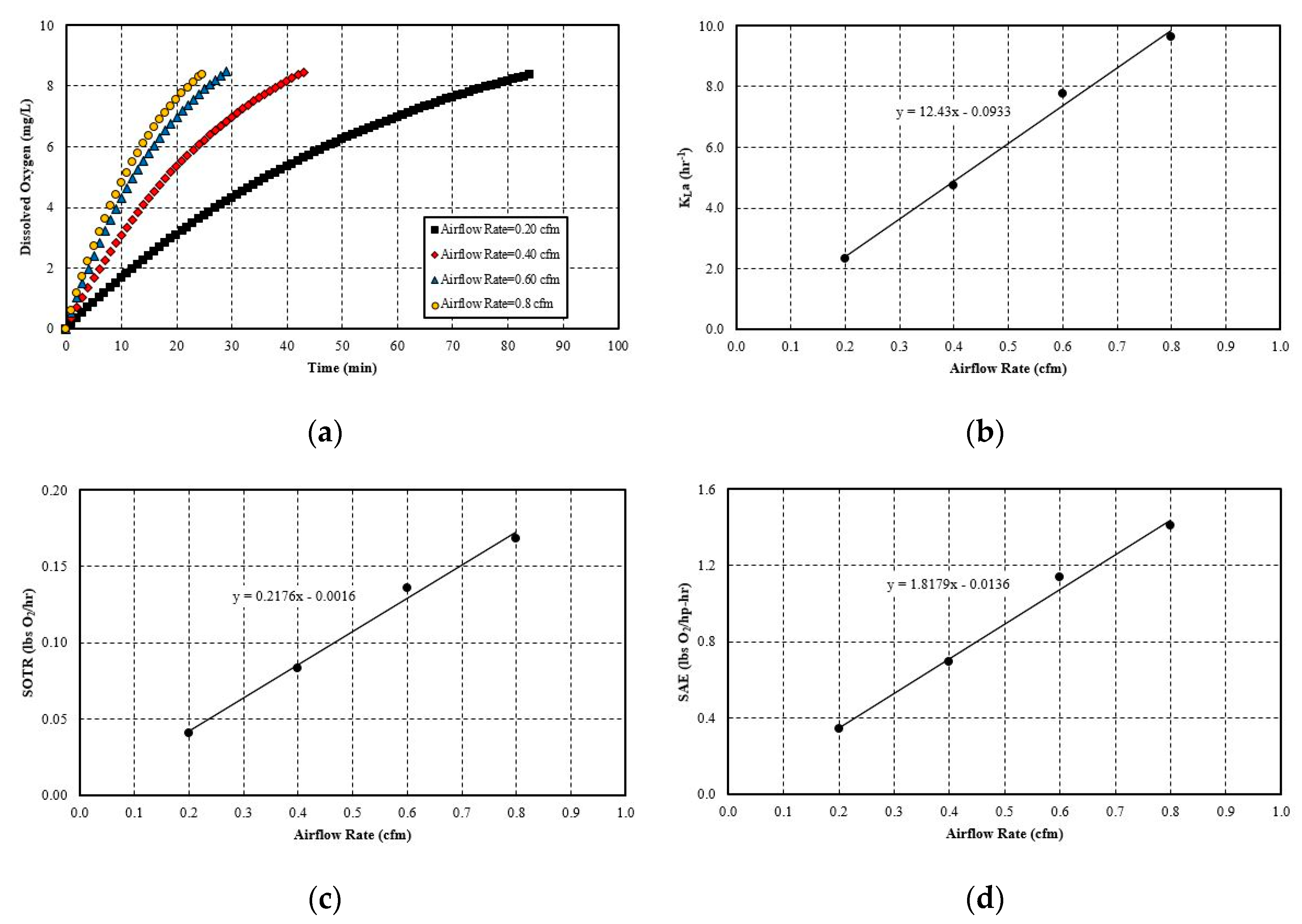
It can be observed from Figure 9 that in all cases of simulation, gas suction flow rates increase significantly the impact of dissolved oxygen level. With the increase in gas flow rate, the dissolved oxygen attains the saturation concentration more rapidly. Gas flow rate basically increases the mass quality in Equation (24). This positive impact can be explained in two ways: firstly, an increase in gas flow rate generally creates more turbulence in the liquid interface. At this point, mass transfer is governed by the disturbance and rate of restoration of the liquid film. This is described by the Danckwertz surface rejuvenation theory [49]:
K L = D L r
where, K L is the liquid film coefficient discussed in Equation (10), D L is the diffusion coefficient of oxygen (m2·h−1) and r is the rate of restoration of liquid the film (h−1). Since an increase in gas flow rate increases the r value in Equation (31), K L also increases. This positive effect of K L also increases the oxygen transfer coefficient and SOTR.
Secondly, a rise in the gas flow rate also increases the number of bubbles at any time. This increase in gas bubbles raises the total available interfacial area to the surrounding medium for diffusion [50,51,52]. In short, this creates favorable conditions for K L a and SOTR. In this discussion, SAE also increases since no flow parameters have been changed. However, in real life this might not be true as the increase in pressure differential and motive flow rate is required to increase the suction gas flow rate for existing venturi. Another way that a gas suction increase is possible is if a new and improved venturi aerator was available. This is currently other promising research in the field of venturi aeration.

5.2.4. Effect of Liquid Flow Rate

In this section, the discussion is made on the effect of liquid flow rate in overall performance of the aeration system. This effect is found ignoring other changes associated with liquid flow rate change like pressure head decreases in pump. The rest of the other conditions of this simulation are same as in test-1.
In Figure 10a, it can be seen that a liquid flow rate increase has adverse effects on the dissolve oxygen rise with time. As the liquid flow rate increases, the system takes more time to reach saturation. On the other hand, no observable trend has been seen for the oxygen transfer coefficient and SOTR. Both the K L a and the SOTR plots against the liquid flow rate have a downward slope which shows the performance degradation of the system with the flow rate. The reasons should be opposite those of the gas flow rate discussion. One factor is that the increasing liquid flow rate decreases the average gas mass fraction at any time. Therefore, less interfacial area is available for mass transfer through diffusion. Additionally, a higher liquid flow rate decreases the bubble contact time. All of these parameters also affect the aeration efficiency of the system negatively.

5.3. Proposed System

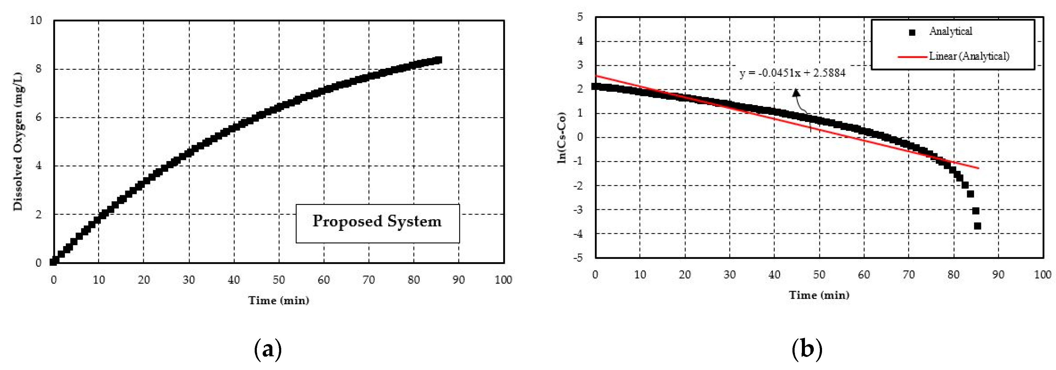
Based on all the previous analysis done in this research, a new system is proposed with the aim to reach an SAE of over 1.5. The proposed system is considered for an assumed real-life problem. Therefore, the size of the system is much larger than the system tested. The problem considered here is that the proposed system needs to aerate an aquaculture (catfish) pond the size of two acres. The average depth of the system is four feet. This gives approximately 26,042 gallons of water to aerate. This analysis is still done based on the assumption of clean water. In the previous section, it was observed that diameter and airflow rate increase have the maximum impact on increasing the efficiency of the aeration system. However, the airflow rate increase comes with higher pressure differentials and motive flow which in turn negatively impacts the SAE. In that case, pipe length increase plays a better role, since frictional head loss is much less through PVC or PEX pipe. A pump size of 5 hp is chosen in this case after calculating the total head developed by the system. Finally, multiple simulations have been done in the analytical model to determine the optimum system to aerate this catfish pond. The input parameters that are found to be useful to get an SAE over 1.5 are given in Table 5. Figure 11a,b represent the dissolved oxygen level and log deficit concentration of oxygen with respect to time in the catfish pond for the proposed setup respectively.
The Mazzei Injector has a catalogue of their different venturi injectors with the best possible air suction rates at different pressure differentials and motive flow rates. From there, a four-inch injector was chosen which is capable of producing an airflow rate of 7 scfm at the pressure differentials and water flow rates described in Table 5. According to these input values, the analytical model gives an oxygen transfer coefficient of 0.045 min−1, an SOTR of 4.38 lbs O2/hr, and an SAE of 1.8.
The possible setup of the proposed system:
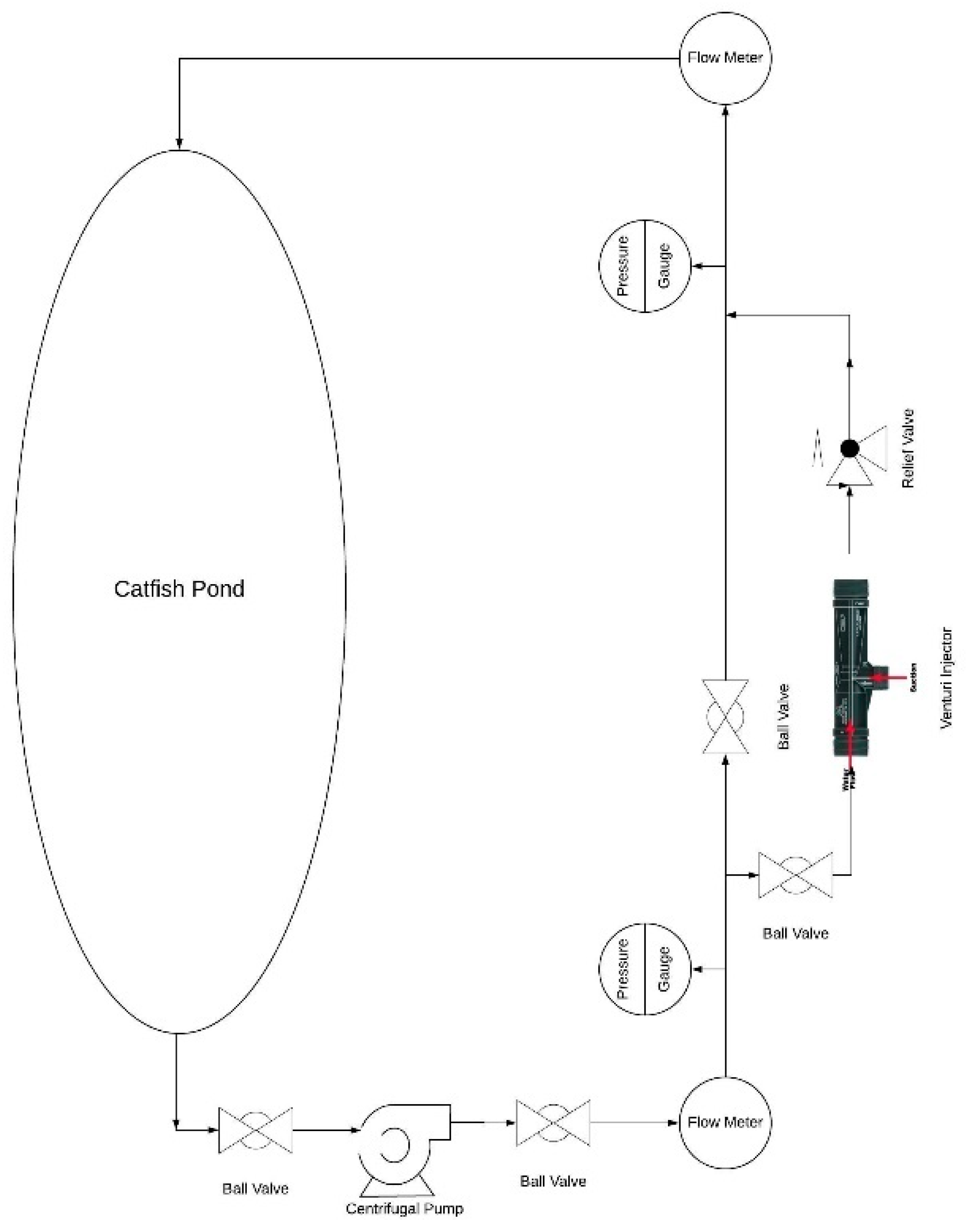
  • The proposed system will be a closed loop system where a pump will be set up on the ground. The water intake of the pump will be at the bottom of the catfish pond.
  • The water will reach the main discharge line located on the ground. There will be a pressure gauge to measure the pressure of the upcoming fluid before it enters into the injector.
  • A pressure reducing valve will be attached to the proposed system in the discharge side of the injector to maintain the desired pressure differential. Therefore, maximum air suction can be achieved.
  • The coiled pipe will start on the discharge side of injector and will hang in from the ground. The pressurized water will be evacuated from the pond on top surface.
  • Finally, the water from the discharge side will be ejected into the catfish pond with high velocity. A schematic of the proposed system is shown in Figure 12.
In Table 6, efficiency ranges for various types of aeration equipment obtained from [53] are listed. However, SAE values in Table 6 can be used only as a reference; exact values are equipment and application specific. In this present study, only one aerator is considered. Since multiple aerators attached in parallel form can cause more air to be injected into water, this type of setup can also be used to increase the efficiency of the overall aeration system [54,55]. Future studies could focus on the effect of multiple parallel aerators on aeration efficiency.

6. Conclusions

In this study, a novel closed loop aeration system is proposed, consisting of a venturi air injector and a coiled pipe coupled with a pump. Several conclusions have been made from this study which are summarized below:
  • The experimental study of the current closed loop venturi aspirated aeration system achieved an SOTR in the range of 0.050–0.068 lbs O2/h and an SAE in the range of 0.42–0.63 lbs O2/hp-h. With the analytical study, SOTR is found to be similar for this system and is 0.047–0.059 lbs O2/h and SAE in the range of 0.37–0.55 lbs O2/hp-h. In all cases, the difference between experimental and analytical results are within 15%. The analytical model underestimates the experimental values, likely because it cannot account for turbulent mixing, bubble breakup, and bubble coalescing.
  • The hydraulic parameters considered herein are the pipe diameter and pipe length. Both significantly impact the system’s aeration efficiency. Increasing the pipe length by a factor of five increases the SAE by 2.5 times. For pipe diameter increase, the effect is more evident, since increasing the diameter by 4 times increases the SAE by 4.1 times. The linear trend line is obtained with a simple mathematical relationship between SAE against the pipe length and diameter. The probable cause for this positive influence is that pipe length increases the bubble contact time with water. Moreover, the bubbles do not migrate towards the pipe wall and try to follow the centerline by avoiding coalesce and breakup. The diameter increase has a similar impact since it reduces the water flow rate and also reduces the frictional head loss. Thereby, it increases the system’s efficiency. The flow parameters that are considered here are: gas flow rate and water flow rate. Gas flow rate seems to play an important role in the system’s efficiency. It is observed that increasing the gas flow rate by 75% increases the SAE by almost 76%. The trend line of SAE versus gas flow rate also shows a linear relationship. The gas flow rate increases the amount of bubbles or gas volume fractions in the continuous medium of water flow at any instant. This results in a higher interfacial area for mass transfer. However, liquid flow rate increase impacts the system in a negative way. It does not give enough time for bubble contact and also reduces the gas volume fraction in the continuous media. There is no observable trend line found between SAE versus liquid flow rate.
  • A system is proposed to optimize SAE based on the limited experimental information in this study. This proposed system is intended for aquaculture (e.g., catfish farm). The proposed system requires a 5-hp pump with 250 feet of 4-inch diameter coiled pipe. A 4-inch diameter venturi injector is chosen which can aspirate 7 scfm of air at 10 psi pressure differential with a water flow rate of 230 gpm. The system has an SOTR of 4.38 lbs O2/h and an SAE of 1.8.

Author Contributions

Conceptualization, D.W.M. and R.M.; methodology, D.W.M. and R.M.; validation, R.M.; formal analysis, R.M.; investigation, R.M. and M.E.; resources, R.M. and M.E.; data curation, R.M.; writing—original draft preparation R.M.; writing, R.M.; review and editing, D.W.M.; visualization, R.M.; supervision, D.W.M.; project administration, D.W.M.; funding acquisition, D.W.M. All authors have read and agreed to the published version of the manuscript.

Funding

This research received no external funding.

Acknowledgments

The authors would like to acknowledge the support from the Department of Energy’s Industrial Assessment Center’s Awards for Excellence in Applied Energy Engineering Research.

Conflicts of Interest

The authors declare no conflict of interest.

References

  1. Alp, E.; Melching, C.S. Allocation of supplementary aeration stations in the Chicago waterway system for dissolved oxygen improvement. J. Environ. Manag. 2011, 92, 1577–1583. [Google Scholar] [CrossRef] [PubMed]
  2. Buscaglia, G.C.; Bombardelli, F.A.; García, M.H. Numerical modeling of large-scale bubble plumes accounting for mass transfer effects. Int. J. Multiph. Flow. 2003, 28, 1763–1785. [Google Scholar] [CrossRef]
  3. Zhang, Z.; Zeng, Y.; Kusiak, A. Minimizing pump energy in a wastewater processing plant. Energy 2012, 47, 505–514. [Google Scholar] [CrossRef]
  4. Brandt, M.; Middleton, R.; Wheale, G.; Schulting, F. Energy efficiency in the water industry, a Global Research Project. Water Pract. Technol. 2011, 6. [Google Scholar] [CrossRef]
  5. Oliver, J.D.; Somerset Environmental Solutions Inc. Apparatus and Method for Aerating Wastewater. U.S. Patent Application 16/090,676.9, 2019. [Google Scholar]
  6. Rosso, D.; Larson, L.E.; Stenstrom, M.K. Aeration of large-scale municipal wastewater treatment plants: State of the art. Water Sci. Technol. 2008, 57, 973–978. [Google Scholar] [CrossRef] [PubMed]
  7. Zhang, J.X. Analysis on the effect of venturi tube structural parameters on fluid flow. AIP Adv. 2017, 7. [Google Scholar] [CrossRef] [Green Version]
  8. Simpson, A.; Ranade, V.V. Modeling hydrodynamic cavitation in venturi: Influence of venturi configuration on inception and extent of cavitation. AIChE J. 2019, 65, 421–433. [Google Scholar] [CrossRef]
  9. Zahradník, J.; Fialová, M.; Linek, V.; Sinkule, J.; Řezníčková, J.; Kaštánek, F. Dispersion efficiency of ejector-type gas distributors in different operating modes. Chem. Eng. Sci. 1997, 52, 4499–4510. [Google Scholar] [CrossRef]
  10. Terasaka, K.; Hirabayashi, A.; Nishino, T.; Fujioka, S.; Kobayashi, D. Development of microbubble aerator for waste water treatment using aerobic activated sludge. Chem. Eng. Sci. 2011, 66, 3172–3179. [Google Scholar] [CrossRef]
  11. Basso, A.; Hamad, F.A.; Ganesan, P. Effects of the geometrical configuration of air–water mixer on the size and distribution of microbubbles in aeration systems. Asia-Pacific J. Chem. Eng. 2018, 13, e2259. [Google Scholar] [CrossRef] [Green Version]
  12. Akhtar, M.S.; Rajesh, M.; Ciji, A.; Sharma, P.; Kamalam, B.S.; Patiyal, R.S.; Singh, A.K.; Sarma, D. Photo-thermal manipulations induce captive maturation and spawning in endangered golden mahseer (Tor putitora): A silver-lining in the strangled conservation efforts of decades. Aquaculture 2018, 497, 336–347. [Google Scholar] [CrossRef]
  13. Bagatur, T. Evaluation of Plant Growth with Aerated Irrigation Water Using Venturi Pipe Part. Arab. J. Sci. Eng. 2014, 39, 2525–2533. [Google Scholar] [CrossRef]
  14. Dahrazma, B.; Naghedinia, A.; Ghasemian Gorji, H.; Saghravani, S.F. Morphological and physiological responses of Cucumis sativus L. to water with micro-nanobubbles. J. Agric. Sci. Technol. 2019, 21, 181–192. [Google Scholar]
  15. Mitra, S.; Daltrophe, N.C.; Gilron, J. A novel eductor-based MBR for the treatment of domestic wastewater. Water Res. 2016, 100, 65–79. [Google Scholar] [CrossRef] [PubMed]
  16. Kaya, Y.; Bacaksiz, A.M.; Bayrak, H.; Gönder, Z.B.; Vergili, I.; Hasar, H.; Yilmaz, G. Treatment of chemical synthesis-based pharmaceutical wastewater in an ozonation-anaerobic membrane bioreactor (AnMBR) system. Chem. Eng. J. 2017, 322, 293–301. [Google Scholar] [CrossRef]
  17. Unsal, M.; Baylar, A.; Tugal, M.; Ozkan, F. Increased aeration efficiency of high-head conduit flow systems. J. Hydraul. Res. 2008, 46, 711–714. [Google Scholar] [CrossRef]
  18. Bunea, F.; Ciocan, G.D. Experimental Study of Standard Aeration Efficiency in a Bubble Column. In Desalination and Water Treatment; IntechOpen: London, UK, 2018. [Google Scholar]
  19. Baylar, A.; Ozkan, F. Applications of venturi principle to water aeration systems. Environ. Fluid Mech. 2006, 6, 341–357. [Google Scholar] [CrossRef]
  20. Baylar, A.; Ozkan, F.; Unsal, M. On the Use of Venturi Tubes in Aeration. CLEAN Soil Air Water 2007, 35, 183–185. [Google Scholar] [CrossRef]
  21. Baylar, A.; Aydin, M.; Unsal, M.; Ozkan, F. Numerical Modeling of Venturi Flows for Determining Air Injection Rates Using Fluent V6.2. Math. Comput. Appl. 2009, 14, 97–108. [Google Scholar] [CrossRef] [Green Version]
  22. Water Resources Institute (US). Measurement of Oxygen Transfer in Clean Water: ASCE Standard, ASCE/EWRI 2-06; American Society of Civil Engineers: Reston, WV, USA, 2007. [Google Scholar]
  23. Mantha, R.; Taylor, K.E.; Biswas, N.; Bewtra, J.K. A continuous system for Fe0 reduction of nitrobenzene in synthetic wastewater. Environ. Sci. Technol. 2001, 35, 3231–3236. [Google Scholar] [CrossRef]
  24. Yin, Z.G.; David, Z.Z.; Liang, B.C.; Wang, L. Theoretical analysis and experimental study of oxygen transfer under regular and non-breaking waves. J. Hydrodyn. 2013, 25, 718–724. [Google Scholar] [CrossRef]
  25. Mazzei Injector Company, LLC. Available online: https://mazzei.net/ (accessed on 14 April 2020).
  26. Eckenfelder, W.W.; Ford, D.L. New concepts in oxygen transfer and aeration. In Advances in Water Quality Improvement; Texas Press: Austin, TX, USA, 1968; pp. 215–236. [Google Scholar]
  27. Barrut, B.; Blancheton, J.P.; Champagne, J.Y.; Grasmick, A. Mass transfer efficiency of a vacuum airlift-Application to water recycling in aquaculture systems. Aquac. Eng. 2012, 46, 18–26. [Google Scholar] [CrossRef] [Green Version]
  28. Kumar, A.; Moulick, S.; Singh, B.K.; Mal, B.C. Design characteristics of pooled circular stepped cascade aeration system. Aquac. Eng. 2013, 56, 51–58. [Google Scholar] [CrossRef]
  29. Kumar, A.; Moulick, S.; Mal, B.C. Selection of aerators for intensive aquacultural pond. Aquac. Eng. 2013, 56, 71–78. [Google Scholar] [CrossRef]
  30. Mueller, J.A.; Boyle, W.C.; Pöpel, H.J. Aeration: Principles and Practice. Popel-Google Books. Available online: https://books.google.com/books?hl=en&lr=&id=t4W9BwAAQBAJ&oi=fnd&pg=PP1&dq=Aeration:+principles+and+practice+%5BM%5D,+vol+9.+CRC+Press&ots=Gh0HKOBfmm&sig=jZ8nJquSAEHwxavK5IKqGR793-U#v=onepage&q=Aeration%3Aprinciplesandpractice%5BM%5D%2Cvol9.CRCPress&f=false (accessed on 12 April 2020).
  31. Wüest, A.; Brooks, N.H.; Imboden, D.M. Bubble plume modeling for lake restoration. Water Resour. Res. 1992, 28, 3235–3250. [Google Scholar] [CrossRef]
  32. Delnoij, E.; Lammers, F.A.; Kuipers, J.A.M.; Van Swaaij, W.P.M. Dynamic simulation of dispersed gas-liquid two-phase flow using a discrete bubble model. Chem. Eng. Sci. 1997, 52, 1429–1458. [Google Scholar] [CrossRef] [Green Version]
  33. Sokolichin, A.; Eigenberger, G.; Lapin, A.; Lübbert, A. Dynamic numerical simulation of gas-liquid two-phase flows: Euler/Euler versus Euler/Lagrange. Chem. Eng. Sci. 1997, 52, 611–626. [Google Scholar] [CrossRef]
  34. Darmana, D.; Deen, N.G.; Kuipers, J.A.M. Detailed modeling of hydrodynamics, mass transfer and chemical reactions in a bubble column using a discrete bubble model. Chem. Eng. Sci. 2005, 60, 3383–3404. [Google Scholar] [CrossRef] [Green Version]
  35. Van Den Hengel, E.I.V.; Deen, N.G.; Kuipers, J.A.M. Application of coalescence and breakup models in a discrete bubble model for bubble columns. Ind. Eng. Chem. Res. 2005, 44, 5233–5245. [Google Scholar] [CrossRef]
  36. Ellis, C.; Karn, A.; Hong, J.; Lee, S.J.; Kawakami, E.; Scott, D.; Gulliver, J.; Arndt, R.E.A. Measurements in the wake of a ventilated hydrofoil: A step towards improved turbine aeration techniques. In Proceedings of the IOP Conference Series: Earth and Environmental Science; IOP Publishing: Bristol, UK, 2014; Volume 22, p. 62009. [Google Scholar]
  37. Zhao, L.; Sun, L.; Mo, Z.; Tang, J.; Hu, L.; Bao, J. An investigation on bubble motion in liquid flowing through a rectangular Venturi channel. Exp. Therm. Fluid Sci. 2018, 97, 48–58. [Google Scholar] [CrossRef]
  38. Burris, V.L.; Little, J.C. Bubble dynamics and oxygen transfer in a hypolimnetic aerator. In Water Science and Technology; Elsevier Sci Ltd.: Amsterdam, The Netherlands, 1998; Volume 37, pp. 293–300. [Google Scholar]
  39. Burris, V.L.; McGinnis, D.F.; Little, J.C. Predicting oxygen transfer and water flow rate in airlift aerators. Water Res. 2002, 36, 4605–4615. [Google Scholar] [CrossRef]
  40. Little, J.C.; McGinnis, D.F. Hypolimnetic oxygenation: Predicting performance using a discrete-bubble model. In Water Science and Technology: Water Supply; IWA Publishing: London, UK, 2001; Volume 1, pp. 185–191. [Google Scholar]
  41. Popel, H.J.; Wagner, M. Prediction of oxygen transfer rates from simple measurements of bubble characteristics. In Water Science and Technology; IWA Publishing: London, UK, 1991; Volume 23, pp. 1941–1950. [Google Scholar]
  42. Biń, A.K. Application of A Single-Bubble Model in Estimation of Ozone Transfer Efficiency in Water. Ozone Sci. Eng. 1995, 17, 469–484. [Google Scholar] [CrossRef]
  43. Orsat, V.; Vigneault, C.; Raghavan, G.S.V. Air Diffusers Characterization using a Digitized Image Analysis System. Appl. Eng. Agric. 1993, 9, 115–121. [Google Scholar] [CrossRef]
  44. McGinnis, D.F.; Little, J.C. Predicting diffused-bubble oxygen transfer rate using the discrete-bubble model. Water Res. 2002, 36, 4627–4635. [Google Scholar] [CrossRef]
  45. Heat Transfer Handbook-Google Books. Available online: https://books.google.com/books?hl=en&lr=&id=d4cgNG_IUq8C&oi=fnd&pg=PR9&dq=Bejan,+Adrian%3B+Kraus,+Allan+D.+(2003).+Heat+Transfer+Handbook.+John+Wiley+%26+Son&ots=27DYj60qWH&sig=P02nCTSSS5a-3b8hlgPtqcQPLqM#v=onepage&q=Bejan%2CAdrian%3BKraus%2CAllan,D.(2003).HeatTransferHandbook.JohnWiley%26Son&f=false (accessed on 12 April 2020).
  46. Gordiychuk, A.; Svanera, M.; Benini, S.; Poesio, P. Size distribution and Sauter mean diameter of micro bubbles for a Venturi type bubble generator. Exp. Therm. Fluid Sci. 2016, 70, 51–60. [Google Scholar] [CrossRef]
  47. Saffari, H.; Moosavi, R.; Gholami, E.; Nouri, N.M. The effect of bubble on pressure drop reduction in helical coil. Exp. Therm. Fluid Sci. 2013, 51, 251–256. [Google Scholar] [CrossRef]
  48. Ekambara, K.; Sanders, R.S.; Nandakumar, K.; Masliyah, J.H. CFD Modeling of Gas-Liquid Bubbly Flow in Horizontal Pipes: Influence of Bubble Coalescence and Breakup. Int. J. Chem. Eng. 2012, 2012, 20. [Google Scholar] [CrossRef] [Green Version]
  49. Dobbins, W.E. Mechanism of Gas Absorption by Turbulent Liquids. In Advances in Water Pollution Research; Elsevier: Amsterdam, The Netherlands, 1964; pp. 61–96. [Google Scholar]
  50. Bewtra, J.; Federation, W.N.-J.; Water, P.C. Oxygenation from diffused air in aeration tanks. Journal 1964, 36, 1195–1224. [Google Scholar]
  51. Bewtra, J.K.; Nicholas, W.R.; Polkowski, L.B. Effect of temperature on oxygen transfer in water. Water Res. 1970, 4, 115–123. [Google Scholar] [CrossRef]
  52. Schmit, F.; Wren, J.; Control, D.R.-J.; Water, P. The effect of tank dimensions and diffuser placement on oxygen transfer. JSTOR 1978, 50, 1750–1767. [Google Scholar]
  53. Tchobanoglous, G.; Burton, F.L.; David Stensel, H. Wastewater Engineering. Management 1991, 7, 1–4. [Google Scholar]
  54. Zhu, J.; Miller, C.F.; Dong, C.; Wu, X.; Wang, L.; Mukhtar, S. Aerator Module Development Using Venturi Air Injectors to Improve Aeration Efficiency. Appl. Eng. Agric. 2007, 23, 661–667. [Google Scholar] [CrossRef]
  55. Dong, C.; Zhu, J.; Wu, X.; Miller, C.F. Aeration efficiency influenced by venturi aerator arrangement, liquid flow rate and depth of diffusing pipes. Environ. Technol. (UK) 2012, 33, 1289–1298. [Google Scholar] [CrossRef] [PubMed]
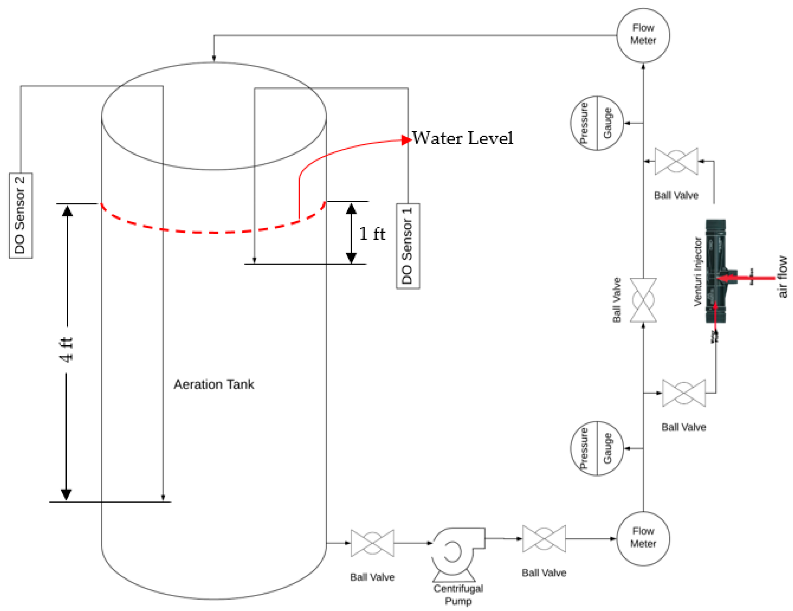
Figure 1. Schematic of Current Experimental Setup.
Water 12 01637 g001
Figure 2. Experimental Setup at the University of Alabama.
Water 12 01637 g002
Figure 3. Two Film theory (absorption of gas molecule).
Water 12 01637 g003
Figure 4. Representation of the Discrete Bubble Model algorithm.
Water 12 01637 g004
Figure 5. Dissolved Oxygen (mg/L) versus Time (min) for three test conditions defined in Table 2: (a) Test-1; (b) Test-2; (c) Test-3.
Water 12 01637 g005
Figure 6. Determination of oxygen transfer coefficient for three test conditions defined in Table 2: (a) Test-1; (b) Test-2; (c) Test-3.
Water 12 01637 g006aWater 12 01637 g006b
Figure 7. Effect of pipe length on: (a) Dissolved (mg/L) oxygen vs. time (min); (b) KLa (h−1); (c) SOTR (lbs O2/h); (d) SAE (lbs O2/hp-h).
Water 12 01637 g007aWater 12 01637 g007b
Figure 8. Effect of pipe diameter on: (a) Dissolved (mg/L) oxygen vs. time (min); (b) KLa (h−1); (c) SOTR (lbs O2/h); (d) SAE (lbs O2/hp-h).
Water 12 01637 g008
Figure 9. Effect of gas flow rate on: (a) Dissolved (mg/L) oxygen vs. time (min); (b) KLa (h−1); (c) SOTR (lbs O2/h); (d) SAE (lbs O2/hp-h).
Water 12 01637 g009
Figure 10. Effect of liquid rate on: (a) Dissolved (mg/L) oxygen vs. time (min); (b) KLa (h−1); (c) SOTR (lbs O2/h); (d) SAE (lbs O2/hp-h).
Water 12 01637 g010
Figure 11. Proposed System: (a) Dissolved (mg/L) oxygen vs. time (min); (b) Determination of oxygen transfer coefficient.
Water 12 01637 g011
Figure 12. A schematic of the proposed system with one aerator.
Water 12 01637 g012
Table 1. List of experimental equipment.
EquipmentQuantity
½ hp Centrifugal Pump1
PEX Pipe (1 in. Dia)20 ft.
Mazzei [25] Venturi Injectors (1 in. Dia)1
Digital Pressure Gauge2
Digital Flow Meter2
Aeration Tank Size (300 Gallons)1
Ball Valve6
Optical DO Probe2
Temperature Sensor1
Table 2. Different physical parameters.
ParameterDimensionsExperimental Value
Test-1Test-2 Test-3
Pipe lengthft202020
Pipe diameterinch111
Venturi injectors111
Injector inlet pressurepsi17.817.814.05
Injector outlet pressurepsi5.411.24.1
Air flow rateSCFM0.3020.1420.2183
Water flow rateCFM1.261.261.13
Aerated water volumeGallons250250250
Temperature °C252525
Reynolds Number (Water) 33,49333,49330,037
Reynolds Number (Mixture) 1,234,1001,434,4001,172,600
Table 3. Performance of aeration experiments.
TestsExperimental Value (EV)Analytical Value (AV)Percentage Difference
| EV AV EV × 100 | %
KLa (h−1)SOTR (lbsO2/h)SAE (lbsO2/hp-h)KLa (h−1)SOTR (lbsO2/h)SAE (lbsO2/hp-h)KLa (%)SOTR (%)SAE (%)
Test-14.030.0680.563.380.0590.49161313
Test-22.870.0500.422.550.0440.37111212
Test-33.200.0540.632.810.0470.55121312
Table 4. Performance of different aeration conditions obtained from the analytical model.
ParameterValuesAnalytical Value
KLa (h−1)SOTR (lbsO2/h)SAE (lbsO2/hp-h)
Pipe Length20 ft.3.380.060.49
40 ft.5.240.090.77
60 ft.7.210.131.05
80 ft.8.200.141.20
100 ft.9.970.171.46
Pipe Diameter1 in.3.380.060.49
2 in9.650.171.41
3 in.12.600.221.84
4 in.15.940.282.33
Airflow Rate0.2 cfm2.340.040.34
0.4 cfm4.750.080.69
0.6 cfm7.770.141.14
0.8 cfm9.620.171.41
Water flow Rate1.26 cfm3.870.070.57
2.52 cfm2.520.040.18
3.78 cfm2.400.040.12
5.04 cfm1.570.030.06
Table 5. Different physical parameters for the proposed system.
ParameterDimensionsInput Value
Pipe lengthft.250
Pipe diameterinch4
Venturi injectors1
Injector inlet pressurepsi15
Injector outlet pressurepsi5
Air flow rateSCFM7
Water flow rateCFM31
Aerated water volumeGallons26,041
Temperature °C25
Table 6. Efficiency of different aeration systems.
TypeSAE (lbs O2/hp-h)
Closed Loop Venturi Aspirated Aeration1.8
Low-Speed Surface Aerators2.5–3.4
High-Speed Surface Aerators1.8–2.3
Submersed Jet Aerators1.6–2.3
Fine Bubble Diffusers, Disks3–10
High Density Low Flux (HDLF) Fine Bubble Diffuser5–13