Article

Produced Water Desalination via Pervaporative Distillation

1
Department of Civil & Environmental Engineering, Institute of the Environment & Sustainability and California NanoSystems Institute, University of California, Los Angeles, CA 90095, USA
2
Long Beach Water Department, Long Beach, CA 90095, USA
3
IntelliFlux Controls, Irvine, CA 90095, USA
4
Pacifica Water Solutions, Northridge, CA 91326, USA
*
Author to whom correspondence should be addressed.
Water 2020, 12(12), 3560; https://doi.org/10.3390/w12123560
Submission received: 23 November 2020 / Revised: 14 December 2020 / Accepted: 15 December 2020 / Published: 18 December 2020

Abstract

:
Herein, we report on the performance of a hybrid organic-ceramic hydrophilic pervaporation membrane applied in a vacuum membrane distillation operating mode to desalinate laboratory prepared saline waters and a hypersaline water modeled after a real oil and gas produced water. The rational for performing “pervaporative distillation” is that highly contaminated waters like produced water, reverse osmosis concentrates and industrial have high potential to foul and scale membranes, and for traditional porous membrane distillation membranes they can suffer pore-wetting and complete salt passage. In most of these processes, the hard to treat feed water is commonly softened and filtered prior to a desalination process. This study evaluates pervaporative distillation performance treating: (1) NaCl solutions from 10 to 240 g/L at crossflow Reynolds numbers from 300 to 4800 and feed-temperatures from 60 to 85 °C and (2) a real produced water composition chemically softened to reduce its high-scale forming mineral content. The pervaporative distillation process proved highly-effective at desalting all feed streams, consistently delivering <10 mg/L of dissolved solids in product water under all operating condition tested with reasonably high permeate fluxes (up to 23 LMH) at optimized operating conditions.

1. Introduction

Pervaporation (PV) is a hybrid distillation process whereby separation performance is a function of the relative solubilities (in the membrane) of the constituents in the feed as well as their relative boiling points. In practice, PV is primarily used for separation of azeotropic liquid mixtures like alcohols and water [1], polar aprotic solvents and water [2], as well as other applications such as bioethanol dehydration [3], production of non-alcoholic wine and beer [4], and catalytically active membranes for reactive-separations [5,6]. While PV has found limited practical application in water desalination to date, pervaporative desalination (PVD) has been studied for over 25 years [7,8].
Various researchers have explored the use of zeolite and carbon molecular sieve-coated ceramic membranes for PVD, where one of the key challenges is making a defect free zeolite coating that is thin enough to give a reasonable flux [9,10,11,12,13,14]. Other studies explored different types of polymeric and mixed matrix membranes applied to PVD [15,16,17,18,19,20]. Several earlier studies have explored the PVD process and even solar powered PVD [21,22,23]. Among the most comprehensive set of studies include those by Gray and co-workers [21,24,25,26,27], who have explored novel polymeric thin film composite and nanocomposite PV membrane materials as well as scaled-up process energy demand and cost; they conclude that PVD (like traditional membrane distillation, MD) will be more expensive and energy intense than RO, so it may be limited to brine concentration, where commercial RO membranes cannot operate at high enough pressures to achieve reasonable permeate recovery [26].
Despite the rather limited practical application of MD and PVD to brine concentration, water sustainability imperatives motivate efforts to achieve minimal or zero liquid discharge (MLD/ZLD) in many desalination applications. As such, the dense separating layer of PV membranes offers a potential advantage over conventional MD. In conventional MD processes, a hydrophobic membrane with pores on the scale of ~0.1 to ~0.5 μm separates the feed and permeate streams; this is depicted in Figure 1a in the form of vacuum MD (VMD). A MD membrane must be very hydrophobic and the pores of sufficient size and shape to maintain a vapor-liquid interface (or meniscus) at each pore entrance [28,29,30,31]. The feed is heated, while the permeate is either cold water, a cool sweep gas or under vacuum—the combined effects lower the trans-membrane partial pressure difference for water leading to evaporation below the boiling point. However, when a hydrophobic MD membrane experiences fouling or scaling the pores become less hydrophobic, reducing the pore liquid entry pressure (LEP) risking “pore wetting”, which leads to salt passage and complete system failure [32]. In contrast, PV employs a dense hydrophilic membrane, which first absorbs liquid water then passes it as water vapor (Figure 1b) [8,33]. The dense hydrophilic PV membrane could lose permeability due to fouling or scaling, but would not suffer process failure as happens in MD.
Herein, we report on the performance of a hybrid organic-inorganic thin film composite PVD membrane evaluated in a process mode identical to that of VMD. We evaluate the effects of feed temperature, crossflow velocity and feed water salinity (up to 240 g/L) to establish a basic understanding of the PVD membrane’s performance characteristics. We then evaluate the potential for treating a real hyper-saline produced water stream derived from upstream oil and gas production via hydraulic fracturing. The organic-inorganic thin film composite membrane was chosen because of its stability under extreme operational conditions (high salinity, temperature, acidity, etc.) [34]. This silica-based amorphous material offers a true hybrid silica pore network in which organic and inorganic fragments cooperate. The hybrid structure provides more stable bonds, lower solubility, and higher crack propagation energy resulting in more ductile material, all of which contribute to its remarkable stability.

2. Materials and Methods

2.1. Materials

The hydrophilic PV membrane used in this study, HybSi® PVM-039, (Pervatech BV, Rijssen, The Netherlands), comprised a proprietary cross-linked organo-silane selective layer casted on an α-Al2O3 tubular ceramic membrane support. The thin coating of selective layer is prepared by a sol-gel process from the bis-silyl precursors, such as BTESE [(EtO)3Si–CH2CH2–Si(OEt)3] and BTESM [(EtO)3Si–CH2–Si(OEt)3], that has been described in detail elsewhere [34,35]. The coating film was on the inside of the ceramic tube. The tube had exterior diameter of 10 mm, an interior diameter of 7 mm and a length of 25 cm giving an active membrane area of 0.005495 m2.
All feed solutions in this study were synthetic solutions made of salts and laboratory de-ionized water (18 M-ohm). Sodium chloride (NaCl), magnesium sulfate heptahydrate (MgSO4·7H2O), calcium chloride dihydrate (CaCl2·2H2O), sodium bicarbonate (NaHCO3), sodium bromide (NaBr), strontium chloride hexahydrate (SrCl2·6H2O), potassium chloride (KCl), iron(II) sulfate heptahydrate (FeSO4·7H2O), sodium sulfate (Na2SO4), sodium metasilicate (Na2SiO3), sodium silicate (Na2O+SiO2·H2O) were purchased from Sigma-Aldrich (St. Louis, Missouri, USA) and used as received.

2.2. PVD Bench-Scale Testing Apparatus

The laboratory PVD setup is depicted in Figure 2. The membrane unit was secured in a cylinder-shaped module. The feed solution was preheated to a desired temperature by circulating it directly through a recirculating heater/chiller bath (Sahara, SCE 150-S3, Thermo Neslab) and returned to an insulated high-density polyethylene (HDPE) feed tank. A separate external thermometer (VWR) was used to directly monitor the temperature inside the feed vessel. During the experiment, the solution was drawn from the feed tank and circulated through the PV membrane module using a gear pump (75211-30 A-Mount Suction, Micropump).
The feed mixture, at elevated temperature and atmospheric pressure, was in direct contact with the interior, hydrophilic organo-silane coated side of the membrane. The permeate was removed in a vapor state from the reverse side of the membrane using a vacuum pump (GAST, Benton Harbor, MI, USA) at a vacuum of 0.85 bar. The vapor was converted into liquid state in a condenser comprising a glass coil attached to a second recirculating heater/chiller set to 5 °C. A graduated cylinder was attached to the condenser outlet to collect permeate.

2.3. Basic PVD System Performance

The PVD system performance was characterized by the observed water flux and salt rejection. The volumetric permeate flux (J) was determined from the permeate mass (M), per unit time (t), density of permeate ( ρ w ) and effective membrane area (A) according to,
J = M ρ w A t
Experiments were performed to evaluate the impact of feed concentration, feed temperature, and feed crossflow velocity on system performance. A serious of aqueous solutions containing 10 to 240 g/L NaCl were chosen to represent the typical salt concentration of brackish water, sea water, and brine streams. Feed temperature was varied in the range of 60 to 85 °C. The feed crossflow velocity was varied to achieve different flow regimes, as reflected by Reynolds number (Re) which is calculated as
R e = ρ u d H µ
where u is the channel average crossflow velocity, ρ is solution density, dH is the hydraulic diameter (m), and μ is the solution viscosity [36,37,38,39]. Both ρ and μ were calculated at its corresponding salinity and temperature [37]. The target Reynolds number was in the range of ~300 to ~4800.
For each set of test conditions, permeate samples were collected for 30 minutes after the system stabilized. The salt concentration of the feed (cf) and permeate (cp) were obtained from measured electrical conductivities with a conductivity meter (Hach, Loveland, CO, USA). The salt concentration of the feed and permeate were determined from measured. The salt rejection (R) was determined by
R = C f C p C f × 100 %
The apparent diffusion coefficient of water was calculated from a simplified version of Fick’s law,
D w = J δ C f C p
where δ is the membrane coating film thickness.
The overall effect of temperature on flux, as well as the solubility and diffusivity of component within the membrane, can be reflected by an apparent activation energy, Ea, based on the Arrhenius relationship,
J = A · e x p ( E a R T )
where J is the permeate flux, A is the pre-exponential factor, R is the ideal gas law constant, and T is the absolute temperature.

2.4. Integrated Membrane Process for Produced Water Desalination

The performance of PVD system was evaluated by treating a simulated produced water using the composition of a real produced water sample. OLI Stream Analyzer software (OLI Systems, Morris Plains, NJ, USA) was used to evaluate solution quality with different ionic compositions. According to the simulation results from OLI, the produced water composition given by the oil & gas producer possessed an extremely high scaling potential particularly at elevated temperatures, which would substantially limit permeate water recovery in the PVD process. Therefore, integrating pre-treatment steps such as lime softening and filtration, is necessary to prevent scaling on the PVD membranes. In this study, slaked lime (CaO, Sigma Aldrich, St. Louis, MO, USA) and soda ash (Na2CO3, Sigma Aldrich, St. Louis, MO, USA) were used to soften synthetic produced water and the precipitated solids were filtered out using a 0.45-μm cellulose acetate membrane (EW-06645-14, Cole Parmer, Vernon Hills, IL, USA).

2.5. Energy Performance of the PVD System

The main energy requirement of the PVD system should include: the thermal energy needed to heat up the feed stream, the electrical energy required to create vacuum and the electrical energy needed to circulate the feed. The thermal energy is the largest energy component, increasing sharply with increasing temperature [40]. The evaluation of the energy consumption of the PVD system is based on the quantities of energy consumed and the quantity of treated water. The specific energy consumption SEC, which is defined as the amount of total energy supplied (heat and electrical energy in this case) to produce a unit mass of pure water [41], was calculated to evaluate the energy performance of the PVD process as [42],
SEC = STEC + SEEC
where STEC is the specific thermal energy consumption, or the specific heat consumption, which can be calculated from the rate of heat input into the PVD system, Q ˙ h e a t , and the mass flow rate of pure water produced, m ˙ p e r as [43],
STEC = Q ˙ h e a t   m ˙ p e r ,
and SEEC is the specific electrical energy consumption defined as the amount of electrical energy consumed, E ˙ , to produce a unit mass of pure water [44],
SEEC = E ˙   m ˙ p e r .
The SEEC value here includes both the vacuum pump and feed recirculating pump.
The required thermal energy includes the initial thermal energy to heat up the feed from ambient temperature to desired temperature, and continuous thermal energy to keep the feed at desired temperature. Thus, the rate of thermal energy input Q ˙ h e a t can be calculated as, [26]
Q ˙ h e a t = m ˙ f C p , f ( T i n ,   f T 0 )
where m ˙ f is the mass flow rate of the feed solution; C p , f is the specific heat capacity of the feed; T 0 and T i n ,   f are the temperature of the feed before heating and feed channel inlet, respectively.
The electrical energy consumption is composed of the energy needed to circulate the feed and to create vacuum on the permeate side. Therefore, the rate of electrical energy input E ˙ is calculated as [45],
E ˙ = E ˙ v a c + E ˙ c i r
E ˙ v a c = 3.35 × 10 3 η v a c T p q 0 ln ( P a t m P v a c )
E ˙ c i r = V ˙ f Δ P η c i r
where, E ˙ c i r and E ˙ v a c are the rate of electrical energy consumption of the feed flow pump and the vacuum pump, respectively; η c i r   and η v a c are the efficiency of feed and vacuum pump, respectively; V ˙ f is the volumetric flow rate of the feed solution; Δ P is the feed bulk pressure difference between the inlet and outlet; T p is the permeate temperature and q 0 is the flow rate of the air to be evacuated from the permeate line; P a t m and P v a c are the atmospheric and vacuum pressures, respectively.

2.6. Model Development

The transport model outputs the system average product water fluxes, which is based on a series of differential mass, momentum and heat balances and employs a forward difference numerical solution. The global average water vapor flux is determined from
J = 0 L J x d x
where the local permeate flux J x is obtained by
J x = A m ( P m f , x P v )
where A m is the membrane permeability, P m f , x is the local partial vapor pressure at feed/membrane interface, P v is the absolute pressure on the permeate side. P m f , x is determined by the local temperature at the feed/membrane interface T m f , i , which can be expressed in Antoine Equation [46]
P m f , x = ( 1 1 + m x ) exp ( 23.1964 3816.44 T m f , x 46.13 )
where m i is the local molar fraction of salt at the feed/membrane interface.
Based on the mass balance of the feed, local cross-flow velocity is determined by [47]
ρ x u x ρ 0 u 0 = 1 h c 0 L ρ x J x d x
where ρ represents feed density, u is the feed velocity, and h c is the feed channel height. The subscript 0 denotes the value of the parameter at the membrane inlet. The density and the viscosity of the feed solution change along the membrane module length. The local feed density can be determined by [37]
ρ x =   3.033405 + 10.1288163 k 8.750567 k 2 + 2.663107 k 3
where the coefficient k is calculated as
k =   9.9559 e 0.004539 m x + 7.0845 e 0.0001638 ( T b , x 273 ) + 3.9093 e 0.00002551 Δ P h , x
where T b , x is the local bulk feed temperature, and Δ P h , x is the local feed pressure. The local feed viscosity μ b , x is obtained by [37]
μ b , x =   μ w , x   ( 1 + 0.0816 m x   0.0122 m x 2   + 0.000128 m x 3 + 0.000629 T b , x ( 1 e 0.7 m x   ) )
where the local viscosity of water μ w , x is calculated as
μ w , x = 2.414 × 10 5 × 10 247.8 T b , x 140
Local hydraulic pressure Δ P h , x is determined by [47]
Δ P h , x = Δ P h , 0 1 2 d H 0 L f s p , x ρ x u x 2 d x
where Δ P h , 0 is the inlet pressure of the feed, d H is the hydraulic diameter which is the diameter of the membrane in this case, f s p , x is the local frictional factor determined by
f s p , x = { 24 R e x 1   ( R e x < 2300 ) 0.079 R e x 0.25   ( R e x 2300 )
Local bulk feed temperature can be estimated from a heat balance [48]
T b , x = 1 ρ x u x c p , x ( ρ 0 u 0 c p , 0 T b , 0 ρ w Δ H x M w h c 0 L J x d x )
where T b , 0 (K) is the inlet bulk feed temperature, ρ w is the density of water, M w is the molar mass of water, Δ H is the latent heat of vaporization of the feed, and c p is the feed specific heat capacity. The local value of both Δ H and c p can be calculated according to the local solute concentration, cx, and temperature, T b , x [38,39]
Δ H x = 1.91846 × 10 6 × ( T b , x T b , x 33.91 ) 2 × ( 1 c x 1000 ρ x )
c p , x = ( 5.328 9.76 × 10 2 S + 4.04 × 10 4 S 2 ) + ( 6.913 × 10 3 + 7.351 × 10 4 S + 3.15 × 10 6 S 2 ) T b , x + ( 9.6 × 10 6 1.927 × 10 6 S + 8.23 × 10 9 S 2 ) T b , x 2 + ( 2.5 × 10 9 + 1.666 × 10 9 S 7.125 × 10 12 S 2 ) T b , x 3
From boundary layer heat transfer theory, temperature at the membrane surface T m , x can be estimated by
T m , x = T b , x J x ρ x M w Δ H h f , x
where h f , x is the local heat transfer coefficient, which can be determined from Nusselt (Nu)-Reynolds (Re)–Prandtl (Pr) relationship [49,50,51],
N u x = d H k T h f , x = { 0.097 R e x 0.73 P r x 0.13   ( R e x < 1600 ) 0.023 R e x 0.8 P r x 0.3   ( R e x > 2200 ) 0.43 R e x 0.59 P r x 0.3   ( 1600 R e x 2200 )
where k T is the thermal conductivity of feed water calculated as [38,39],
l o g 10 ( k T ,   x ) = l o g 10 ( 240 + 0.0002 S ) + 0.434 × ( 2.3 343.5 + 0.037 S T b , x ) ( 1 T b , x 647 + 0.03 S ) 0.333
The salt concentration of the bulk feed c b is determined by [47]
c b , x = c b , 0 u 0 u x
Accounting for concentration polarization [52], the salinity at the membrane surface c m is determined by
c m , x = c b , x exp ( J x k f , x )
where k f , x (m/s) is the local mass transfer coefficient given by Sherwood (Sh) – Reynolds (Re) -Schmidt (Sc) relationship as the following,
S h x = k f , x d H D = { 1.65 ( R e x S c x d H L ) 0.33   ( R e x < 1600 ) 0.04 R e x 0.75 S c x 0.33   ( R e x > 2200 ) 1.65 ( R e x S c x d H L ) 0.33 + 0.04 R e x 0.75 S c x 0.33   ( 1600 R e x 2200 )
where S c x is the local Schmidt number ( = μ x ρ x D ), and D x is the local diffusion coefficient of NaCl.

3. Results and Discussion

3.1. Membrane Flux

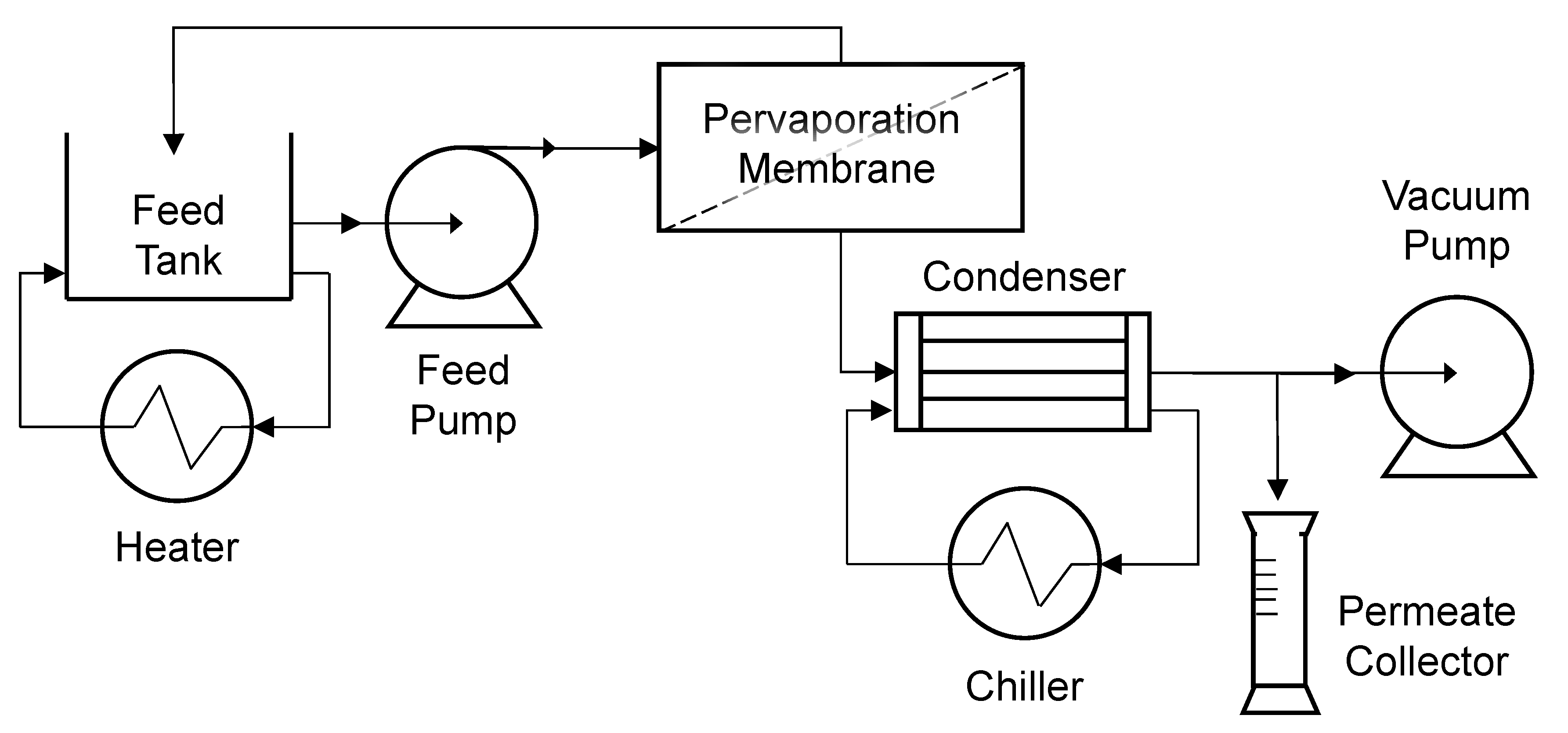
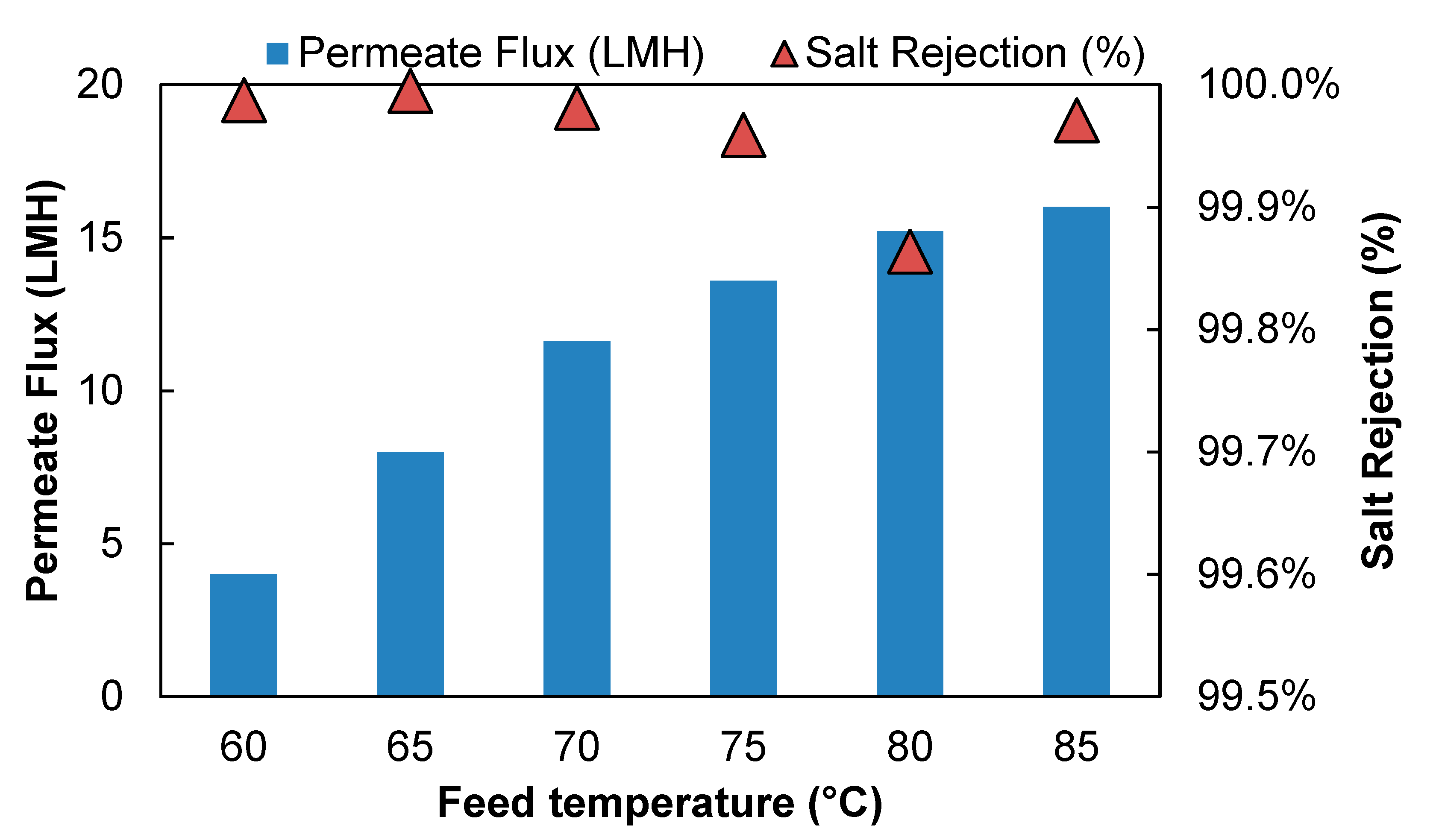
Figure 3 shows the effect of feed temperature on the PVD system performance desalinating 15 g/L NaCl solution. The feed flow rate was maintained at 0.56 L/min to keep the feed flow channel Reynolds number at 4800. As feed temperature increased from 60 °C to 85 °C, the water flux increases from 4.3 LMH to 16 LMH. A higher water flux was expected at a higher temperature, because the partial vapor pressure difference between the feed and permeate side, which is the driving force of a PVD process, is strongly affected by temperature. As the feed temperature increased, the water vapor pressure on the feed side increases, whereas the vapor pressure on the permeate side remains unchanged. As a result, the vapor pressure difference across the membrane increased which led to an increase in vapor flux.
In addition, the increase in temperature also increases water diffusion through the membrane, likely through a combination of higher bulk diffusivity and more swollen (open) membrane pore structure, resulting in higher water permeability (Table 1). Based on free volume theory [53], momentary free volumes are created by the thermal motion of polymer chains in an amorphous region; therefore, as the temperature increased, the free volume of the membranes could increase the higher frequency and amplitude of chain motion. When the polymer-free volumes increase, water molecules diffuse through with less resistance; combined with a higher bulk diffusivity, the apparent water permeability and observed water flux increased.
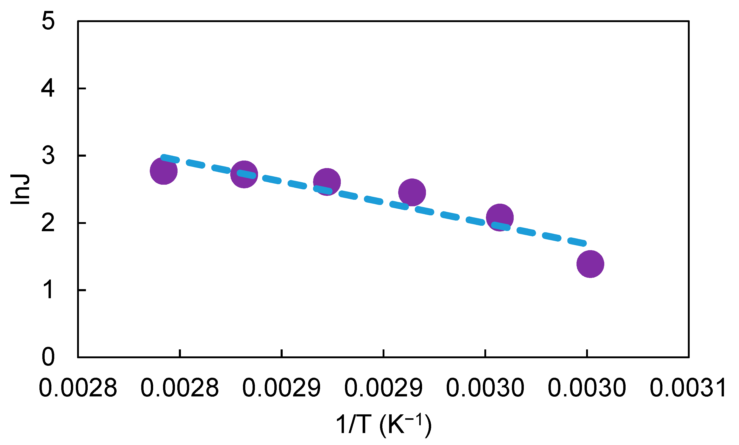
Figure 4 shows a linear Arrhenius plot of the natural logarithm of water flux versus reciprocal temperature. The apparent activation energy Ea of water in the membrane was determined to be 32.6 kJ/mol from the slope of the Arrhenius plot. Compare to other studies, the apparent activation energy of water in the Hybsi membrane is similar to other hybrid pervaporative membranes, where the activation energy in those membranes were reported to be in the range of 11.8–45 kJ/mol, depending on the different membrane materials and operating conditions [25,54,55,56,57,58]. The positive activation energy implies that permeation flux increases with increasing temperature [25], as confirmed by the results shown in Figure 3.
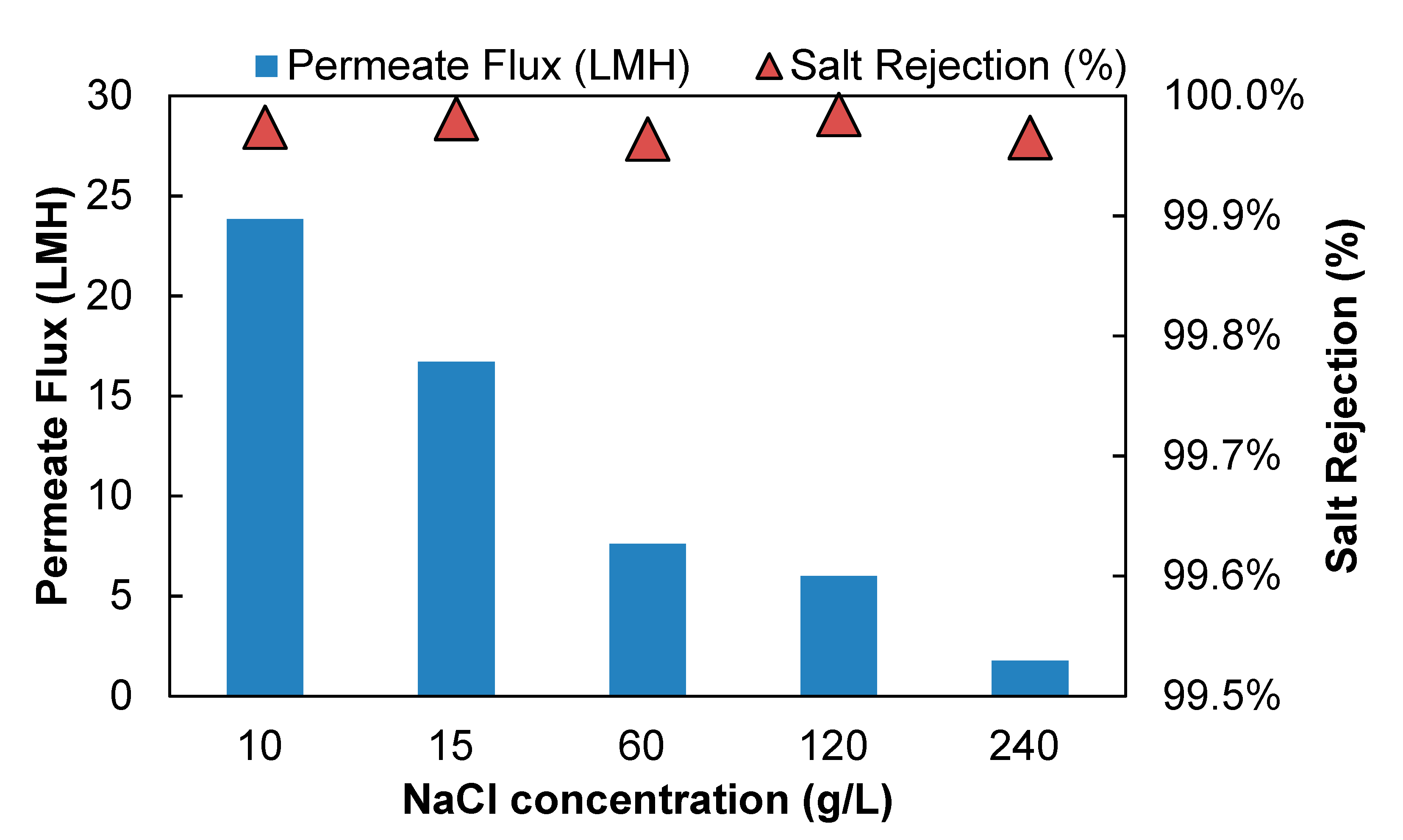
The impact of salt concentration on separation performance of aqueous salt solution is shown in Figure 5. At the temperatures of 85 °C with crossflow Reynolds number of 4800, the water flux decreased from 23.84 LMH to 1.76 LMH when NaCl concentration in the feed increased from 10 g/L to 240 g/L. Table 2 demonstrates the membrane surface temperature, surface salinity, and partial vapor pressure difference (i.e., the driving force) under different feed salt concentration calculated with the model described in Section 2.6. The results show that as feed salt concentration increased, the concentration polarization got significantly worse (evidenced by more than 20 times of the membrane surface salt concentration at 240 g/L feed compared to 10 g/L feed concentration). The membrane surface temperature change with different feed concentration is minimal. The driving force for permeation (feed-side interfacial water partial pressure) decreased ~10% when NaCl concentration increased from 10 g/L to 240 g/L (Table 2). Feed salt concentration is believed to directly affect the water sorption at the liquid/membrane interface [25], because water concentration in the feed decreased as salt concentration increased, which led to the water concentration decrease in the membrane. The substantial change in membrane surface salinity could also change in membrane structure thus membrane permeability, which also plays a role decrease in flux with feed concentration (Equation (16)). These findings indicate that the mass transfer on the feed side was significantly limited by the extent of concentration polarization.
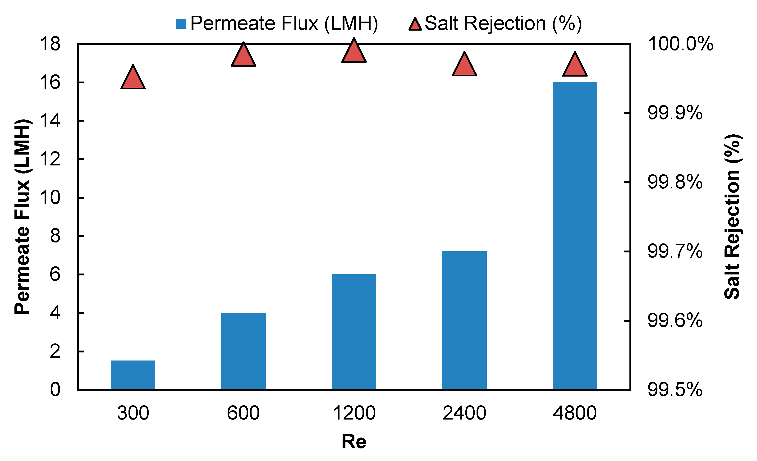
Figure 6 shows the effect of the feed crossflow Reynolds number on the pervaporation performance of the PVD system when the feed flow rate varied from 0.04 to 0.56 L/min at the feed concentration of 15 g/L and temperature of 85 °C. Permeate vapor flux substantially increased from 1.5 LMH to 16 LMH when the feed crossflow Reynolds number increased from 300 to 4800. As Re number increases, assuming the change in water diffusivity with temperature is directly proportional to T, the water diffusivity increase due to temperature increase is less than 3.6%. In Table 3, we present the membrane surface temperature, surface salinity, and partial vapor pressure difference under different hydraulic conditions calculated with the model described in Section 2.6. The results show that as feed flow rate increased, the flow regime in the feed channel changed from laminar flow to turbulent flow, which helped to reduce concentration polarization (evidenced by lower membrane surface salt concentration) and temperature polarization (evidenced by higher membrane surface temperature). In contrast, the driving force for permeation (feed-side interfacial water partial pressure) is almost three times higher at Re 4800 than for Re 300 (Table 3). The change in membrane surface temperature and salinity could also change in membrane structure, which could account for the additional increase in flux with temperature (Equation (14)). These findings imply that the mass transfer on the feed side was significantly limited by the extent of concentration and/or temperature polarization, which is consistent with results from other studies [25]. Therefore, both polarization phenomena need to be managed to enhance mass transfer in PVD systems.

3.2. Salt Rejection

The observed NaCl rejection of PVD system remained above 99.86% under all the tested operating conditions, which is similar to the typical rejections in conventional VMD processes [28,29,30,31]. The permeate salt concentrations were below 10 mg/L in all cases. The high salt rejection was expected because NaCl, as a non-volatile compound, is not likely to penetrate the dense PV membrane material and enter the vapor stream on the permeate side. The mass transfer in a PVD process can be described by solution-diffusion model, which indicates that sorption selectivity is more dependent on the affinity between the membrane active layer and the permeants in the solution [8,59]. As the Hybsi membrane used in the study is hydrophilic in nature [60], the much smaller water molecules should preferentially partition into the membrane, diffuse across the dense coating film and evaporate through the porous ceramic support. While some salt uptake by the coating film is likely to occur, being non-volatile there is no obvious mechanism for NaCl to make its way into the distillate [8,25].

3.3. Synthetic Produced Water Treatment with PVD Process

Produced water ranges in dramatically in quality and composition depending on the geological formation as well as the oil & gas production method employed; a comprehensive review is beyond the scope of this study, but the reader is directed to other references for more details [61,62]. The water quality (after de-oiling) of an actual produced water provided by a large California oil & gas producer (anonymity requested) is reported in the third column from the left in Table 4. According to this water quality, synthetic PW water was made (see recipe in Table 5) and tested in the PVD process. The results from the OLI simulations are shown in the columns to the right in Table 4. The fourth and fifth column represents the same ionic concentration at the temperature of 25 °C and 85 °C, respectively. As shown in Table 4, the solid concentration increased from 8.64 mg/L at 25 °C to 1208 mg/L at 85 °C, which indicates that the synthetic produced water possessed an extremely high scaling potential at elevated operating temperatures. Therefore, warm lime softening and membrane filtration were integrated as pre-treatment to prevent scaling on the PV membranes. The last column shows the water quality after addition of slaked lime and soda ash to reduce scaling potential. The solids were filtered with 0.45-micron membrane at high temperature before feeding the produced water into the bench scale PVD system.
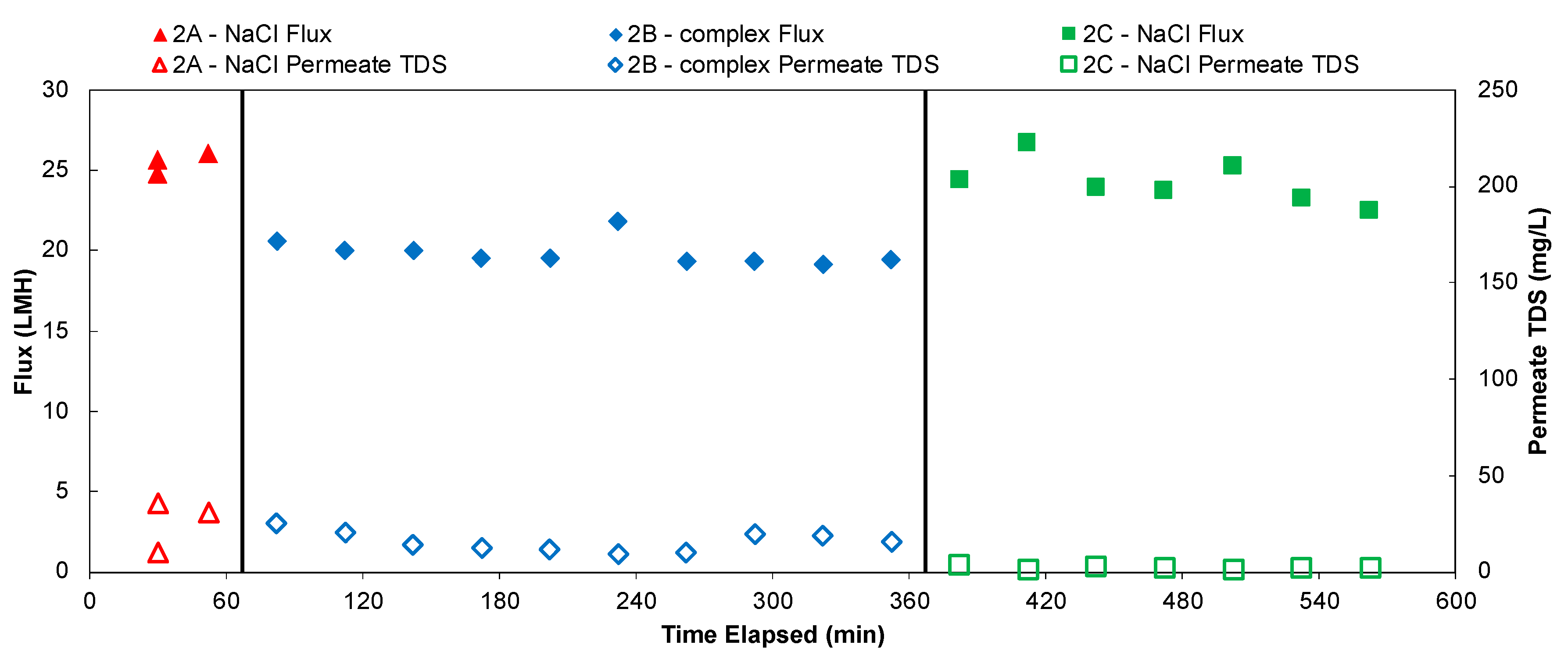
Figure 7 shows the flux and permeate water quality of a 10 h long experiment of desalinating feed solutions that contain 10 g/L TDS, with feed crossflow Reynolds number of 4800, feed water temperature of 85 °C and permeate vacuum of 0.85 bar. Permeate flux and TDS were monitored and recorded every 30 min. In the first ~1 h of the experiment, the feed solution to the system only contains 10 g/L NaCl. The feed water was changed to the softened produced water recipe (TDS = 10 g/L) in the second experiments that lasted for 5 h. Then the feed was changed back to 10 g/L NaCl for the final 4 h. The flux was relatively stable throughout, but water vapor flux declined slightly when the feed water was changed from NaCl solution to the softened produced water solution. The flux bounced back to similar level when the feed water was switched back to NaCl, therefore the effect appears reversible. This can be explained by the change in driving force on the feed side. Although the two feed solutions tested here had the same TDS, the difference in ion composition of the solution could lead to a difference in ionic strength, water activity, salt ion diffusivity and concentration polarization. Compared to NaCl solution, the synthetic produced water contains more multi-valent ions that lower the water activity of the solution, which essentially decreased water vapor pressure on the feed side [63,64,65]. The impact of feed electrolyte composition on water flux through membranes have also been investigated in other studies and a similar trend was reported that the feed solution with multiple ions tend to show lower flux [9,55,66,67]. Regarding the permeate TDS values, it stayed at a fairly constant level despite the change in feed solutions.
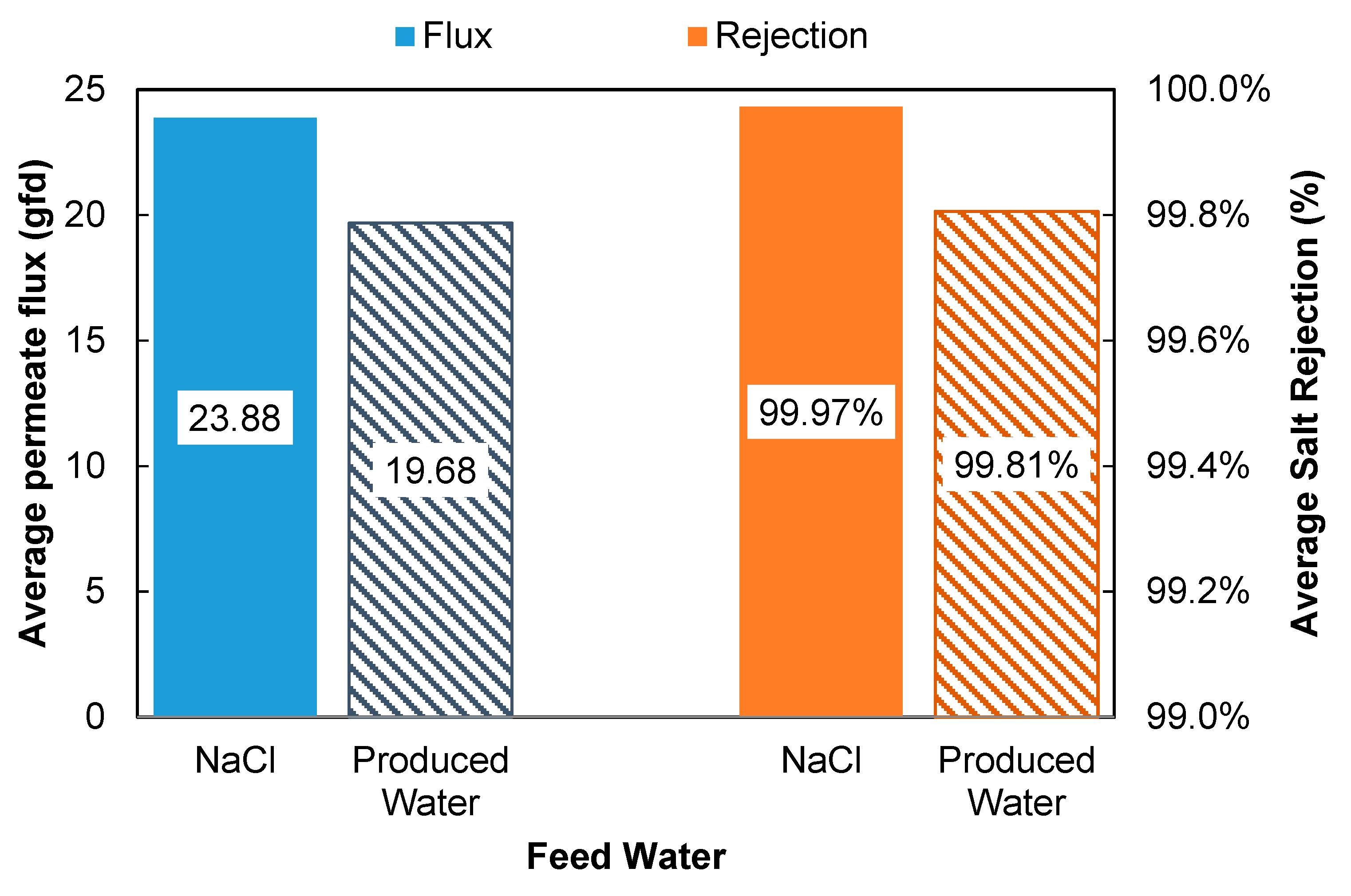
A side by side comparison of the performance data from the produced water and NaCl solution is shown in Figure 8. The results indicate that the PVD process was able to produce high quality permeate (>99.8% rejection) at 19.7 LMH and 85 °C. Compare to other PVD processes with silica-based membranes reported in literature (Table 6), the PVD system in this study has exhibited relatively high water vapor flux and salt rejection. More importantly, the PVD system in this study demonstrated stable performance when tested in extreme operating conditions, such as high feed concentration, temperature and cross-flow velocity.

3.4. PVD Process Energy Performance

Herein, we chose a scenario to investigate the SEC of the PVD process when the system was operated to treat synthetic produced water (TDS = 10 g/L) at 85 °C with cross-flow Reynolds number of 4800 and permeate vacuum of 0.85 bar. 
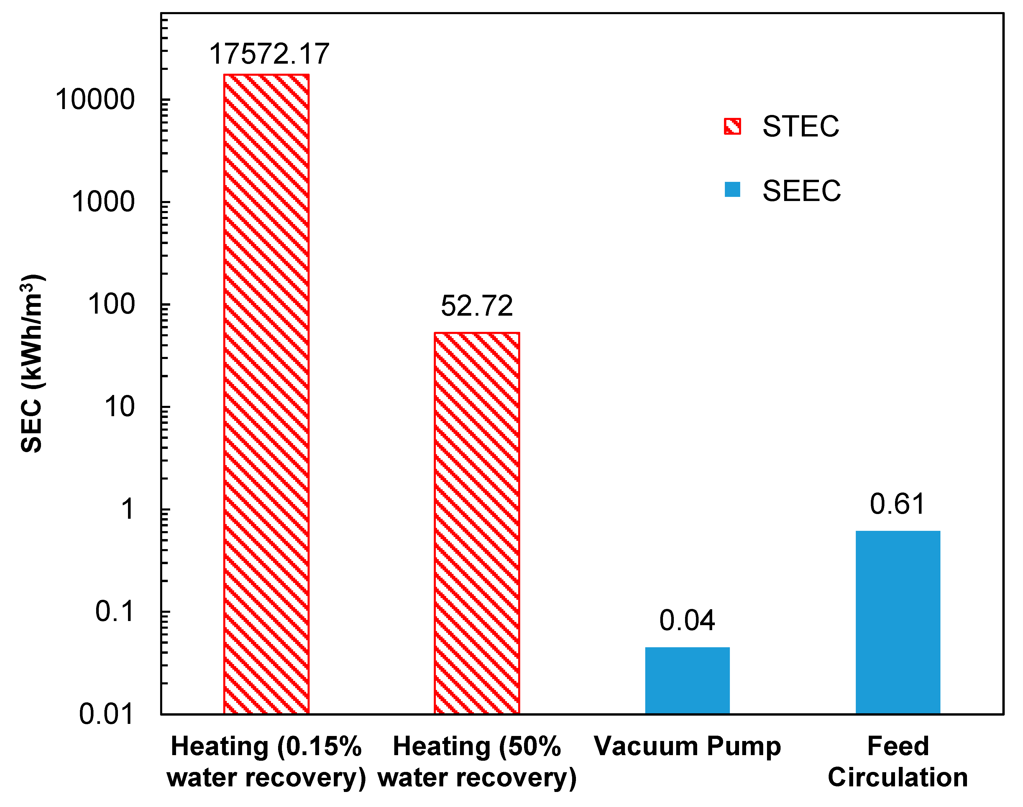
Figure 9 shows a breakdown of the different energy components for PVD of the produced water and the NaCl feed solution. It is clear that the specific thermal energy consumption dominants the overall SEC. In a lab-scale system with low water recovery such as the one demonstrated here (~0.15% recovery), a total amount of 17.6 MWh thermal energy was needed to heat up the feed from ambient temperature to 85 °C to generate permeate flux at the rate of 23.8 LMH. In a full-scale system with a much higher water recovery (typ., 30 to 90%), the required thermal energy drops down to 52.7 kW·h/m3 at 50% water recovery. Compared to thermal energy, the electrical energy remains negligible, as indicated by the small SEEC values in Figure 8. Note that the SEC values are very sensitive to permeate flux, which could vary substantially as a function of recovery and other operating conditions.
Although the SEC values reported here only reflect the energy performance of one specific PVD system operating at a preset condition, the conclusion still holds that PVD would likely be more energy-intense at scale than other desalination processes such as reverse osmosis (RO), reverse electrodialysis (RED), multi-stage flush (MSF), multi-effect distillation (MED), and vapor compression (VC). The findings are consistent with other studies that PVD requires very little electricity, but consumes large amount of thermal energy [8,26,78]. In fact, the electrical energy needed for PVD is the lowest compare to other desalination technologies (Table 7) [78,79,80]. If low grade or waste heat could be harvested and/or renewable energy such as solar thermal energy could be integrated to provide the thermal energy needed to drive a PVD process, the overall fossil fuel-derived energy consumption of PVD process could be dramatically lower [21,22,23,26]. Additionally, heat recovery could be considered as another strategy to lower thermal energy consumption.
The results showed that pervaporative desalination cannot compete with other desalination technologies directly from the perspective of specific energy consumption. However, PVD process still possesses some advantages that might make it attractive in some applications. First of all, PVD process is capable of desalinating hypersaline feed (up to 240 g/L from this study) such as oil and gas hydraulic fracturing produced water; thus, it can be implemented to concentrate wastewater on-site and facilitate minimal liquid discharge, directly, and if combined with a crystallizer, zero liquid discharge. Second, when waste heat or solar heat is integrated to provide “free” thermal energy, PVD requires much less electrical energy compared to other thermal process such as MSF and MED. In addition, PVD is more robust and less prone to system failure compare to traditional porous membrane-based MD processes, which suffer from pore-wetting related process failure.

4. Conclusions

Pervaporative distillation for saline water desalination has not been widely studied, despite the extensive applications of pervaporation to organic/water and organic/organic separations. In this study, a commercial ceramic-supported, cross-linked organosilane-based hydrophilic pervaporation membrane was tested using a bench-scale PVD apparatus. Results from PVD experiments suggest higher feed temperature, lower feed salt concentration, higher feed cross-flow rate, and simpler feed composition all contribute to higher permeate water flux. Observed conductivity rejection exceeded 99.9% with feed salt concentration up to 250,000 mg/L except for the more complex brackish feed electrolyte, which produced 99.81% conductivity rejection. This PVD process was proven to be an effective treatment option for hyper-saline, hard-to-treat water that can consistently deliver high product water quality (<10 mg/L of TDS) under all operating conditions tested, and high permeate flux (up to 23.8 LMH) under optimized operating conditions. The analysis of energy consumption of PVD process indicates that the high thermal energy consumption is the main energy requirement and appears to be the obstacle of scaling up. If coupled with wasted heat or solar energy, PVD still has the potential to become an efficient and promising desalination technology with optimized engineering processes.

Author Contributions

J.W.: Visualization, modeling, writing—review and editing; D.T.: investigation, writing—original draft; S.B.: supervision, visualization, funding acquisition; A.E.: supervision, visualization, funding acquisition; D.J.: funding acquisition, writing—review and editing; E.M.V.H.: supervision, visualization, funding acquisition, modeling, writing—review and editing. All authors have read and agreed to the published version of the manuscript.

Funding

This research was funded by Water Planet Engineering (DT, SB, AE, EMVH), the UCLA Sustainable LA Grand Challenge (EMVH) and the U.S. Department of Energy Award No. DE-EE0008391 (JW, DJ, EMVH), The APC was funded by the UCLA Samueli Engineering School.

Acknowledgments

The experimental work presented herein was performed and an initial manuscript was prepared at Water Planet Engineering by DT, SB, AE and EMVH. The authors would also like to acknowledge many valuable conversations with Frans Velterop at Pervatech B.V. in The Netherlands, the supplier of the Hybsi© membranes used in this study.

Conflicts of Interest

The authors declare that they have no known competing financial interests or personal relationships that could have appeared to influence the work reported in this paper.

References

  1. Jyothi, M.S.; Reddy, K.R.; Soontarapa, K.; Naveen, S.; Raghu, A.V.; Kulkarni, R.V.; Suhas, D.P.; Shetti, N.P.; Nadagouda, M.N.; Aminabhavi, T.M. Membranes for dehydration of alcohols via pervaporation. J. Environ. Manag. 2019, 242, 415–429. [Google Scholar] [CrossRef]
  2. Vane, L.M. Review: Membrane materials for the removal of water from industrial solvents by pervaporation and vapor permeation. J. Chem. Technol. Biotechnol. 2019, 94, 343–365. [Google Scholar] [CrossRef] [PubMed]
  3. Zheng, P.; Li, C.; Wang, N.; Li, J.; An, Q. The potential of pervaporation for biofuel recovery from fermentation: An energy consumption point of view. Chin. J. Chem. Eng. 2019, 27, 1296–1306. [Google Scholar] [CrossRef]
  4. Castro-Muñoz, R. Pervaporation-based membrane processes for the production of non-alcoholic beverages. J. Food Sci. Technol. 2019, 56, 2333–2344. [Google Scholar] [CrossRef] [PubMed]
  5. Castro-Muñoz, R.; Iglesia, Ó.D.L.; Fíla, V.; Téllez, C.; Coronas, J. Pervaporation-Assisted Esterification Reactions by Means of Mixed Matrix Membranes. Ind. Eng. Chem. Res. 2018, 57, 15998–16011. [Google Scholar] [CrossRef]
  6. Qing, W.; Li, X.; Shao, S.; Shi, X.; Wang, J.; Feng, Y.; Zhang, W.; Zhang, W. Polymeric catalytically active membranes for reaction-separation coupling: A review. J. Membr. Sci. 2019, 583, 118–138. [Google Scholar] [CrossRef]
  7. Korngold, E.; Korin, E. Air sweep water pervaporation with hollow fiber membranes. Desalination 1993, 91, 187–197. [Google Scholar] [CrossRef]
  8. Xie, Z.; Li, N.; Wang, Q.; Bolto, B. Desalination by pervaporation. Emerg. Technol. Sustain. Desalin. Handb. 2018, 205–226. [Google Scholar] [CrossRef]
  9. Cho, C.H.; Oh, K.Y.; Kim, S.K.; Yeo, J.G.; Sharma, P. Pervaporative seawater desalination using NaA zeolite membrane: Mechanisms of high water flux and high salt rejection. J. Membr. Sci. 2011, 371, 226–238. [Google Scholar] [CrossRef]
  10. Khajavi, S.; Jansen, J.C.; Kapteijn, F. Production of ultra pure water by desalination of seawater using a hydroxy sodalite membrane. J. Membr. Sci. 2010, 356, 52–57. [Google Scholar] [CrossRef]
  11. Malekpour, A.; Nasiri, H. High performance pervaporative desalination of saline waters using Na-X zeolite membrane. Membr. Water Treat. 2017, 8, 437–448. [Google Scholar] [CrossRef]
  12. Song, Y.; Wang, D.K.; Birkett, G.; Martens, W.; Duke, M.C.; Smart, S.; da Diniz Costa, J.C. Mixed Matrix Carbon Molecular Sieve and Alumina (CMS-Al2O3) Membranes. Sci. Rep. 2016, 6, 30703. [Google Scholar] [CrossRef] [PubMed] [Green Version]
  13. An, W.; Zhou, X.; Liu, X.; Chai, P.W.W.; Kuznicki, T.; Kuznicki, S.M.M. Natural zeolite clinoptilolite-phosphate composite Membranes for water desalination by pervaporation. J. Membr. Sci. 2014, 470, 431–438. [Google Scholar] [CrossRef]
  14. Swenson, P.; Tanchuk, B.; Gupta, A.; An, W.; Kuznicki, S.M. Pervaporative desalination of water using natural zeolite membranes. Desalination 2012, 285, 68–72. [Google Scholar] [CrossRef]
  15. Nigiz, F.U. Complete desalination of seawater using a novel polyvinylidene fluoride/zeolite membrane. Environ. Chem. Lett. 2018, 16, 553–559. [Google Scholar] [CrossRef]
  16. Nigiz, F.U. Preparation of high-performance graphene nanoplate incorporated polyether block amide membrane and application for seawater desalination. Desalination 2018, 433, 164–171. [Google Scholar] [CrossRef]
  17. Nigiz, F.U.; Hilmioglu, N.D. Pervaporative desalination of seawater by using composite and blended poly(vinyl alcohol) membranes. Desalin. Water Treat. 2016, 57, 4749–4755. [Google Scholar] [CrossRef]
  18. Nigiz, F.U.; Veli, S.; Hilmioglu, N.D. Deep purification of seawater using a novel zeolite 3A incorporated polyether-block-amide composite membrane. Sep. Purif. Technol. 2017, 188, 90–97. [Google Scholar] [CrossRef]
  19. Uğur Nigiz, F. Preparation of a zeolite 4A loaded polyether block amide membrane and usage for seawater desalination. Pamukkale Univ. J. Eng. Sci. 2018, 24, 1308–1314. [Google Scholar] [CrossRef] [Green Version]
  20. Wu, D.; Gao, A.; Zhao, H.; Feng, X. Pervaporative desalination of high-salinity water. Chem. Eng. Res. Des. 2018, 136, 154–164. [Google Scholar] [CrossRef]
  21. Xie, Z.; Hoang, M.; Duong, T.; Ng, D.; Dao, B.; Gray, S. Sol-gel derived poly(vinyl alcohol)/maleic acid/silica hybrid membrane for desalination by pervaporation. J. Membr. Sci. 2011, 383, 96–103. [Google Scholar] [CrossRef] [Green Version]
  22. Kuznetsov, Y.P.; Kruchinina, E.V.; Baklagina, Y.G.; Khripunov, A.K.; Tulupova, O.A. Deep desalination of water by evaporation through polymeric membranes. Russ. J. Appl. Chem. 2007, 80, 790–798. [Google Scholar] [CrossRef]
  23. Zwijnenberg, H.J.; Koops, G.H.; Wessling, M. Solar driven membrane pervaporation for desalination processes. J. Membr. Sci. 2005, 250, 235–246. [Google Scholar] [CrossRef]
  24. Xie, Z.; Hoang, M.; Ng, D.; Doherty, C.; Hill, A.; Gray, S. Effect of heat treatment on pervaporation separation of aqueous salt solution using hybrid PVA/MA/TEOS membrane. Sep. Purif. Technol. 2014, 127, 10–17. [Google Scholar] [CrossRef] [Green Version]
  25. Xie, Z.; Ng, D.; Hoang, M.; Duong, T.; Gray, S. Separation of aqueous salt solution by pervaporation through hybrid organic-inorganic membrane: Effect of operating conditions. Desalination 2011, 273, 220–225. [Google Scholar] [CrossRef] [Green Version]
  26. Xie, Z.; Ng, D.; Hoang, M.; Zhang, J.; Gray, S. Study of hybrid PVA/MA/TEOS pervaporation membrane and evaluation of energy requirement for desalination by pervaporation. Int. J. Environ. Res. Public Health 2018, 15, 1913. [Google Scholar] [CrossRef] [Green Version]
  27. Yang, G.; Xie, Z.; Cran, M.; Ng, D.; Gray, S. Enhanced desalination performance of poly (vinyl alcohol)/carbon nanotube composite pervaporation membranes via interfacial engineering. J. Membr. Sci. 2019, 579, 40–51. [Google Scholar] [CrossRef]
  28. Deshmukh, A.; Boo, C.; Karanikola, V.; Lin, S.; Straub, A.P.; Tong, T.; Warsinger, D.M.; Elimelech, M. Membrane distillation at the water-energy nexus: Limits, opportunities, and challenges. Energy Environ. Sci. 2018, 11, 1177–1196. [Google Scholar] [CrossRef]
  29. Eykens, L.; De Sitter, K.; Dotremont, C.; Pinoy, L.; Van der Bruggen, B. Membrane synthesis for membrane distillation: A review. Sep. Purif. Technol. 2017, 182, 36–51. [Google Scholar] [CrossRef]
  30. Lawson, K.W.; Lloyd, D.R. Membrane distillation. J. Membr. Sci. 1996, 120, 111–121. [Google Scholar] [CrossRef]
  31. Alkhudhiri, A.; Darwish, N.; Hilal, N. Membrane distillation: A comprehensive review. Desalination 2012, 287, 2–18. [Google Scholar] [CrossRef]
  32. Urtiaga, A.M.; Gorri, E.D.; Ruiz, G.; Ortiz, I. Parallelism and differences of pervaporation and vacuum membrane distillation in the removal of VOCs from aqueous streams. Sep. Purif. Technol. 2001, 22, 327–337. [Google Scholar] [CrossRef]
  33. Korin, E.; Ladizhensky, I.; Korngold, E. Hydrophilic hollow fiber membranes for water desalination by the pervaporation method. Chem. Eng. Process. Process. Intensif. 1996, 35, 451–457. [Google Scholar] [CrossRef]
  34. Agirre, I.; Arias, P.L.; Castricum, H.L.; Creatore, M.; Ten Elshof, J.E.; Paradis, G.G.; Ngamou, P.H.T.; Van Veen, H.M.; Vente, J.F. Hybrid organosilica membranes and processes: Status and outlook. Sep. Purif. Technol. 2014, 121, 2–12. [Google Scholar] [CrossRef] [Green Version]
  35. Paradis, G.G.; Shanahan, D.P.; Kreiter, R.; van Veen, H.M.; Castricum, H.L.; Nijmeijer, A.; Vente, J.F. From hydrophilic to hydrophobic HybSi® membranes: A change of affinity and applicability. J. Membr. Sci. 2013, 428, 157–162. [Google Scholar] [CrossRef]
  36. El-Dessouky, H.T.; Ettouney, H.M. Fundamentals of Salt Water Desalination; Elsevier, B.V.: Amsterdam, The Netherlands, 2002; ISBN 0-444-50810-4. [Google Scholar]
  37. Adams, J.J.; Bachu, S. Equations of state for basin geofluids: Algorithm review and intercomparison for brines. Geofluids 2002, 2, 257–271. [Google Scholar] [CrossRef]
  38. Henderson-Sellers, B. A new formula for latent heat of vaporization of water as a function of temperature. Q. J. R. Meteorol. Soc. 1984, 110, 1186–1190. [Google Scholar] [CrossRef]
  39. Sharqawy, M.H.; Lienhard, J.H.V.; Zubair, S.M. Thermophysical properties of seawater: A review of existing correlations and data. Desalin. Water Treat. 2010, 16, 354–380. [Google Scholar] [CrossRef]
  40. Mericq, J.P.; Laborie, S.; Cabassud, C. Evaluation of systems coupling vacuum membrane distillation and solar energy for seawater desalination. Chem. Eng. J. 2011, 166, 596–606. [Google Scholar] [CrossRef]
  41. Deniz, E.; Çınar, S. Energy, exergy, economic and environmental (4E) analysis of a solar desalination system with humidification-dehumidification. Energy Convers. Manag. 2016, 126, 12–19. [Google Scholar] [CrossRef]
  42. Miladi, R.; Frikha, N.; Kheiri, A.; Gabsi, S. Energetic performance analysis of seawater desalination with a solar membrane distillation. Energy Convers. Manag. 2019, 185, 143–154. [Google Scholar] [CrossRef]
  43. Soomro, M.I.; Kim, W.S. Performance and economic investigations of solar power tower plant integrated with direct contact membrane distillation system. Energy Convers. Manag. 2018, 174, 626–638. [Google Scholar] [CrossRef]
  44. Luo, A.; Lior, N. Critical review of membrane distillation performance criteria. Desalin. Water Treat. 2016, 57, 20093–20140. [Google Scholar] [CrossRef]
  45. McCabe, W.L.; Smith, J.C.; Harriott, P. Unit Operations of Chemical Engineering, 4th ed.; McGraw-Hill: New York, NY, USA, 1985. [Google Scholar]
  46. Olatunji, S.O.; Camacho, L.M. Heat and mass transport in modeling membrane distillation configurations: A review. Front. Energy Res. 2018, 6, 1–18. [Google Scholar] [CrossRef]
  47. Hoek, E.M.V.V.; Allred, J.; Knoell, T.; Jeong, B.-H.H. Modeling the effects of fouling on full-scale reverse osmosis processes. J. Membr. Sci. 2008, 314, 33–49. [Google Scholar] [CrossRef]
  48. Ali, A.; Quist-Jensen, C.A.; Macedonio, F.; Drioli, E. Optimization of module length for continuous direct contact membrane distillation process. Chem. Eng. Process. Process. Intensif. 2016, 110, 188–200. [Google Scholar] [CrossRef]
  49. Gryta, M.; Tomaszewska, M.; Morawski, A.W. Membrane distillation with laminar flow. Sep. Purif. Technol. 1997, 11, 93–101. [Google Scholar] [CrossRef]
  50. Taler, D.; Taler, J. Determining heat transfer correlations for transition and turbulent flow in ducts. Sci. Lett. Rzesz. Univ. Technol. Mech. 2014, 103–114. [Google Scholar] [CrossRef] [Green Version]
  51. Taler, D.; Taler, J. Simple heat transfer correlations for turbulent tube flow. In Proceedings of the E3S Web of Conferences, Szczyrk, Poland, 25–27 October 2017. [Google Scholar]
  52. Mulder, J. Basic Principles of Membrane Technology, 2nd ed.; Kluwer Academic Publishers: Doordrecht, The Netherlands, 1997; ISBN 0-7923-4248-8 (PB). [Google Scholar]
  53. Burshe, M.C.; Sawant, S.B.; Joshi, J.B.; Pangarkar, V.G. Sorption and permeation of binary water-alcohol systems through PVA membranes crosslinked with multifunctional crosslinking agents. Sep. Purif. Technol. 1997, 12, 145–156. [Google Scholar] [CrossRef]
  54. Prihatiningtyas, I.; Gebreslase, G.A.; Van der Bruggen, B. Incorporation of Al2O3 into cellulose triacetate membranes to enhance the performance of pervaporation for desalination of hypersaline solutions. Desalination 2020, 474, 114198. [Google Scholar] [CrossRef]
  55. Halakoo, E.; Feng, X. Layer-by-layer assembly of polyethyleneimine/graphene oxide membranes for desalination of high-salinity water via pervaporation. Sep. Purif. Technol. 2020, 234, 116077. [Google Scholar] [CrossRef]
  56. Reino Olegário da Silva, D.A.; Bosmuler Zuge, L.C.; de Paula Scheer, A. Preparation and characterization of a novel green silica/PVA membrane for water desalination by pervaporation. Sep. Purif. Technol. 2020, 116852. [Google Scholar] [CrossRef]
  57. Zhang, H.Y.; Wen, J.L.; Shao, Q.; Yuan, A.; Ren, H.T.; Luo, F.Y.; Zhang, X.L. Fabrication of La/Y-codoped microporous organosilica membranes for high-performance pervaporation desalination. J. Membr. Sci. 2019, 584, 353–363. [Google Scholar] [CrossRef]
  58. Selim, A.; Toth, A.J.; Haaz, E.; Fozer, D.; Szanyi, A.; Hegyesi, N.; Mizsey, P. Preparation and characterization of PVA/GA/Laponite membranes to enhance pervaporation desalination performance. Sep. Purif. Technol. 2019, 221, 201–210. [Google Scholar] [CrossRef] [Green Version]
  59. Wijmans, J.G.; Baker, R.W. The solution-diffusion model: A review. J. Membr. Sci. 1995, 107, 1–21. [Google Scholar] [CrossRef]
  60. Pervatech Data Sheet HybSi ® Pervaporation Membrane; Pervatech BV: Rijssen, The Netherlands, 2012.
  61. Benko, K.L.; Drewes, J.E. Produced water in the Western United States: Geographical distribution, occurrence, and composition. Environ. Eng. Sci. 2008, 25, 239–246. [Google Scholar] [CrossRef]
  62. Blondes, M.S.; Gans, K.D.; Engle, M.A.; Kharaka, Y.K.; Reidy, M.E.; Saraswathula, V.; Thordsen, J.J.; Rowan, E.L.; Morrissey, E.A. U.S. Geological Survey National Produced Waters Geochemical Database v2.3; U.S. Geological Survey: Reston, Virginia, 2018. [Google Scholar]
  63. Shibue, Y. Vapor pressures of aqueous NaCl and CaCl2 solutions at elevated temperatures. Fluid Phase Equilib. 2003, 213, 39–51. [Google Scholar] [CrossRef]
  64. Troller, J. Methods to Measure Water Activity. J. Food Prot. 1983, 46, 129–134. [Google Scholar] [CrossRef]
  65. Sereno, A.M.; Hubinger, M.D.; Comesaña, J.F.; Correa, A. Prediction of water activity of osmotic solutions. J. Food Eng. 2001, 49, 103–114. [Google Scholar] [CrossRef]
  66. Cha-Umpong, W.; Dong, G.; Razmjou, A.; Chen, V. Effect of oscillating temperature and crystallization on graphene oxide composite pervaporation membrane for inland brine desalination. J. Membr. Sci. 2019, 588, 117210. [Google Scholar] [CrossRef]
  67. Cha-Umpong, W.; Hosseini, E.; Razmjou, A.; Zakertabrizi, M.; Korayem, A.H.; Chen, V. New molecular understanding of hydrated ion trapping mechanism during thermally-driven desalination by pervaporation using GO membrane. J. Membr. Sci. 2020, 598, 117687. [Google Scholar] [CrossRef]
  68. Elma, M.; Hairullah; Assyaifi, Z.L. Desalination Process via Pervaporation of Wetland Saline Water. Iop Conf. Ser. Earth Environ. Sci. 2018, 175, 012009. [Google Scholar] [CrossRef]
  69. Elma, M.; Yacou, C.; da Diniz Costa, J.; Wang, D. Performance and Long Term Stability of Mesoporous Silica Membranes for Desalination. Membranes 2013, 3, 136–150. [Google Scholar] [CrossRef] [PubMed] [Green Version]
  70. Duke, M.C.; Mee, S.; da Costa, J.C.D. Performance of porous inorganic membranes in non-osmotic desalination. Water Res. 2007, 41, 3998–4004. [Google Scholar] [CrossRef]
  71. Darmawan, A.; Karlina, L.; Astuti, Y.; Sriatun; Motuzas, J.; Wang, D.K.; da Costa, J.C.D. Structural evolution of nickel oxide silica sol-gel for the preparation of interlayer-free membranes. J. Non-Cryst. Solids 2016, 447, 9–15. [Google Scholar] [CrossRef]
  72. Elma, M.; Wang, D.K.; Yacou, C.; Motuzas, J.; da Diniz Costa, J.C. High performance interlayer-free mesoporous cobalt oxide silica membranes for desalination applications. Desalination 2015, 365, 308–315. [Google Scholar] [CrossRef]
  73. Lin, C.X.C.; Ding, L.P.; Smart, S.; da Diniz Costa, J.C. Cobalt oxide silica membranes for desalination. J. Colloid Interface Sci. 2012, 368, 70–76. [Google Scholar] [CrossRef]
  74. Yang, H.; Elma, M.; Wang, D.K.; Motuzas, J.; da Diniz Costa, J.C. Interlayer-free hybrid carbon-silica membranes for processing brackish to brine salt solutions by pervaporation. J. Membr. Sci. 2017, 523, 197–204. [Google Scholar] [CrossRef] [Green Version]
  75. Elma, M.; Wang, D.K.; Yacou, C.; da Diniz Costa, J.C. Interlayer-free P123 carbonised template silica membranes for desalination with reduced salt concentration polarisation. J. Membr. Sci. 2015, 475, 376–383. [Google Scholar] [CrossRef]
  76. Wang, S.; Wang, D.K.; Smart, S.; da Costa, D. Improved stability of ethyl silicate interlayer-free membranes by the rapid thermal processing (RTP) for desalination. Desalination 2017, 402, 25–32. [Google Scholar] [CrossRef]
  77. Wang, S.; Wang, D.K.; Motuzas, J.; Smart, S.; da Diniz Costa, J.C. Rapid thermal treatment of interlayer-free ethyl silicate 40 derived membranes for desalination. J. Membr. Sci. 2016, 402, 25–32. [Google Scholar] [CrossRef]
  78. Kaminski, W.; Marszalek, J.; Tomczak, E. Water desalination by pervaporation—Comparison of energy consumption. Desalination 2018, 433, 89–93. [Google Scholar] [CrossRef]
  79. Hoang, M.; Bolto, B.; Haskard, C.; Barron, O.; Gray, S.; Leslie, G. Desalination in Australia; CSIRO: Canberra, Australia, 2009. [Google Scholar]
  80. Khalifa, A.J.N. Evaluation of different hybrid power scenarios to Reverse Osmosis (RO) desalination units in isolated areas in Iraq. Energy Sustain. Dev. 2011, 15, 49–54. [Google Scholar] [CrossRef]
  81. Ahmed, F.E.; Hashaikeh, R.; Hilal, N. Hybrid technologies: The future of energy efficient desalination—A review. Desalination 2020, 495, 114659. [Google Scholar] [CrossRef]
  82. Cherif, H.; Belhadj, J. Environmental Life Cycle Analysis of Water Desalination Processes. In Sustainable Desalination Handbook: Plant Selection, Design and Implementation; Elsevier BV: Amsterdam, The Netherlands, 2018; ISBN 9780128094969. [Google Scholar]
Figure 1. Comparison between (a) VMD and (b) PVD.
Water 12 03560 g001
Figure 2. Schematic of the bench-scale PVD system.
Water 12 03560 g002
Figure 3. The impact of feed temperature on PVD system performance with cross-flow Reynolds number of 4800, feed NaCl concentration of 15 g/L and permeate vacuum of 0.85 bar. The blue bars represent permeate flux (y-axis on the left) and the red triangle dots represent salt rejection (y-axis on the right).
Water 12 03560 g003
Figure 4. Arrhenius plot of the water flux at crossflow Reynolds number of 4800, feed NaCl concentration of 15 g/L and permeate vacuum of 0.85 bar. The purple rounds represent experimental data and the blue dotted line is the linear regression line.
Water 12 03560 g004
Figure 5. The impact of feed concentration on PVD system performance at 85 °C with crossflow Reynolds number of 4800 and permeate vacuum of 0.85 bar. The blue bars represent permeate flux (y-axis on the left) and the red triangle dots represent salt rejection (y-axis on the right).
Water 12 03560 g005
Figure 6. The impact of feed crossflow Reynolds number on PVD system performance at 85 °C with 15 g/L NaCl solution and permeate vacuum of 0.85 bar. The blue bars represent permeate flux (y-axis on the left) and the red triangle dots represent salt rejection (y-axis on the right).
Water 12 03560 g006
Figure 7. Water flux and permeate TDS of 3 continuous desalination experiments in the PVD system, with feed crossflow Reynolds number of 4800, feed water temperature of 85 °C and permeate vacuum of 0.85 bar. The red triangles and green squares represent data from experiments with 10 g/L NaCl feed solutions and the blue diamonds represent data from experiments with synthetic produced water (TDS = 10 g/L) feed solutions. The solid markers represent flux data and the empty markers represent permeate TDS data.
Water 12 03560 g007
Figure 8. Comparison of system performance when desalinating 10g/L NaCl solution and synthetic produced water (TDS = 10 g/L). The bars in blue and red represent flux and salt rejection data, respectively.
Water 12 03560 g008
Figure 9. Breakdown of specific energy consumption in kW·h/m3 (presented in log scale) of the PVD system when desalinating synthetic produced water (TDS = 10 g/L) at 85 °C with cross-flow Reynolds number of 4800 and permeate vacuum of 0.85 bar. The blue solid bars and red hatch bars represent specific electrical and thermal energy consumption, respectively.
Water 12 03560 g009
Table 1. Apparent diffusion coefficient of water at different temperatures.
Temperature (°C)Water Diffusion Coefficient (×10−10 m2/s)
606570758085
15g/L NaCl Re = 48000.691.392.022.372.652.79
Table 2. Simulation results of parameters values with different NaCl concentration.
NaCl Concentration (g/L)Modeling Results with 85 °C Feed and Re 4800
101560120240
Average surface temperature (°C)79.779.779.679.479.3
Average surface salinity (g/L)10.215.361.2122.4244.6
Partial vapor pressure difference (kPa)29.929.829.028.026.2
Table 3. Simulation results of parameters values with different Re.
ReModeling Results with Feed Contains 15 g/L NaCl @ 85 °C
300600120024004800
Average surface temperature (°C)67.672.176.376.679.7
Average surface salt concentration (g/L)17.117.417.515.415.3
Partial vapor pressure difference (kPa)11.517.423.924.429.8
Table 4. Reported and Analyzed Produced Water Quality.
SymbolProduced Water Quality (mg/L)OLI Adjusted @ 25 °C (mg/L)OLI Adjusted @ 85 °C (mg/L)OLI after Softening at 85 °C (mg/L)
ChlorideCl42584207.924378.514180.88
BromideBr1918.6418.6418.66
SulfateSO42−17171697.70950.001694.44
Total Alkalinityas HCO3296.2304.18115.579.01
SodiumNa+12471386.361493.643657.54
PotassiumK+7373.4273.4273.51
CalciumCa2+12831281.27912.550.01
MagnesiumMg2+341.2394.44394.440.02
StrontiumSr2−27.327.9324.200.34
SilicaSiO23232.0032.000.07
IronFe22.012.010.01
pH 6.236.236.2310.17
Solid formedMg in 1 L 8.641208.007579.00
Table 5. Synthetic Produced Water Recipe.
ChemicalFormulaConcentration (mg/L)
Sodium chlorideNaCl5020.90
Magnesium sulfate heptahydrateMgSO4·7H2O3361.02
Calcium chloride dihydrateCaCl2·2H2O4641.78
Sodium bicarbonateNaHCO3407.80
Sodium bromideNaBr24.47
Strontium chloride hexahydrateSrCl2·6H2O81.19
Potassium chlorideKCl139.19
Iron(II) sulfate heptahydrateFeSO4·7H2O10.00
Sodium sulfateNa2SO4539.56
Sodium silicateNa2SiO3139.08
Table 6. Comparison of PVD process performance with silica-based membranes.
Feed CompositionFeed TDS (g/L)Feed Temperature (°C)Flux (LMH)Salt Rejection (%)Reference
silicanatural saline water17.1–30.526–600.33–1.1969.9–99.9[68]
silicaNaCl3–150221.5–6.5>90[69]
La25Y75-BTESE-SiO2NaCl3–7525–607.9–15.6>99.9[57]
PVA-MA-silicaNaCl2–5022–658–11.7>99.9[25]
PVA-MA-silicaNaCl2226.9399.5[21]
PVA-MA-silicaNaCl26511.799.9[26]
MTES-SiO2NaCl35252.690[70]
Amorphous molecular sieve silicaNaCl35251.897[70]
nickel oxide silicaNaCl3–3525–602.5–691.5–99.9[71]
interlayer-free cobalt oxide silicaNaCl3–7522–607.7–20>99.7[72]
cobalt oxide silicaNaCl10–7525–750.2–1.8>99[73]
P123-silicaNaCl0–15025–609.2–19.8>98.4[74]
P123-silicaNaCl3–7522–602.2–7.5>99.5[75]
ES40-silicaNaCl3–3525–602–4.6>99[76]
ES40-silicaNaCl3–3525–601.8–2.32>99[77]
Hybsi®NaCl10–24060–851.5–23.8>99.9This study
Hybsi®Synthetic produced water108519.6899.81This study
Table 7. Energy consumption for various desalination technologies [80,81,82].
ProcessThermal Energy (kWh/m3)Electrical Energy (kWh/m3)
MSF12–243.5–5
MED12.2–19.12–2.5
VC-thermal14.61.5–2
VC-mechanicalN/A7–12
RO-seawaterN/A3–7
RO-brackish waterN/A0.5–2.5
ED-brackish waterN/A2.6–5.5
MSF—multi-stage flush, MED—multi-effect distillation, VC—vapor compression, RO—reverse osmosis, ED—electrodialysis.
Publisher’s Note: MDPI stays neutral with regard to jurisdictional claims in published maps and institutional affiliations.

