Flow Characteristics and Bed Morphology in a Compound Channel between Two Single Channels


Abstract
:1. Introduction
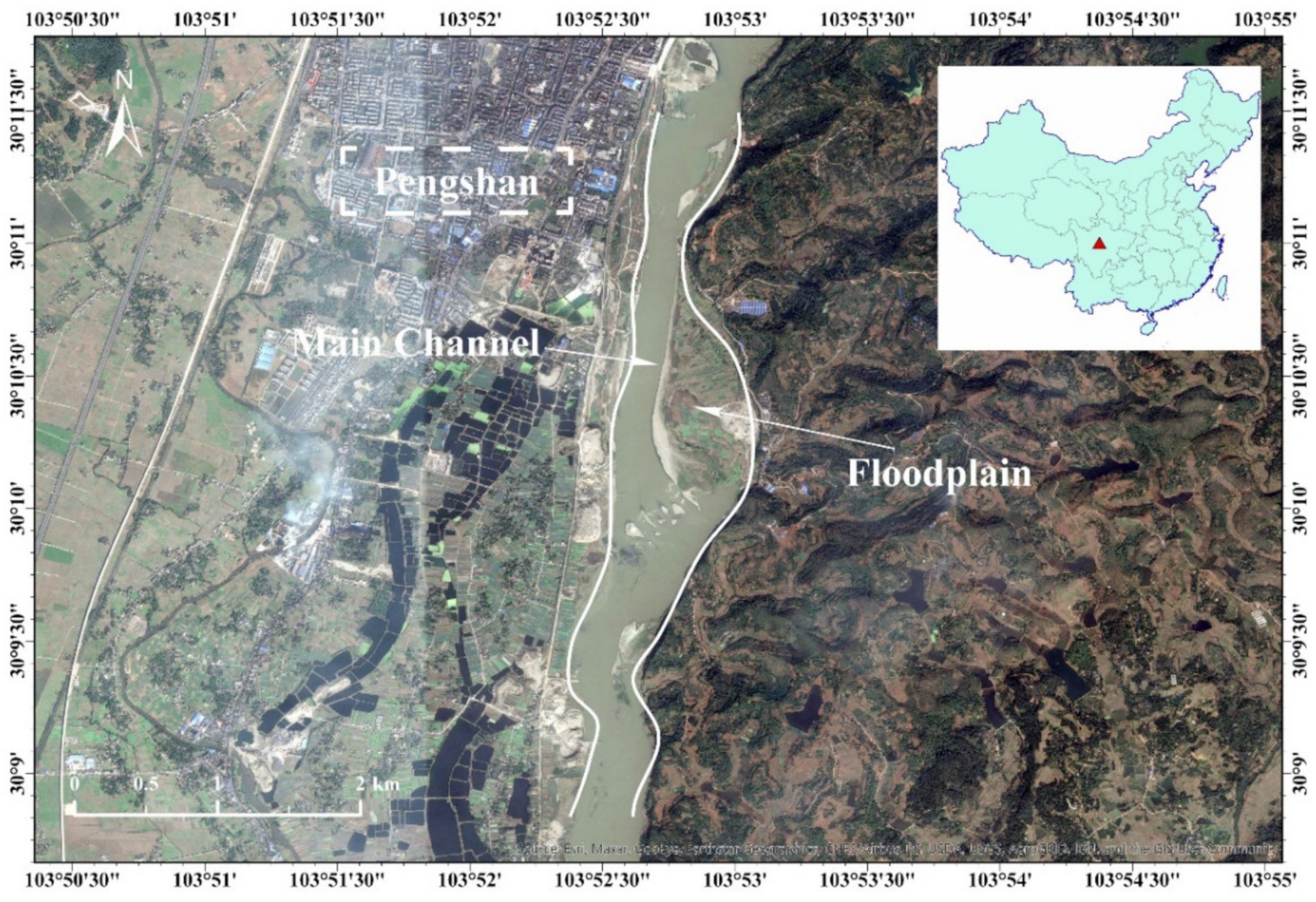
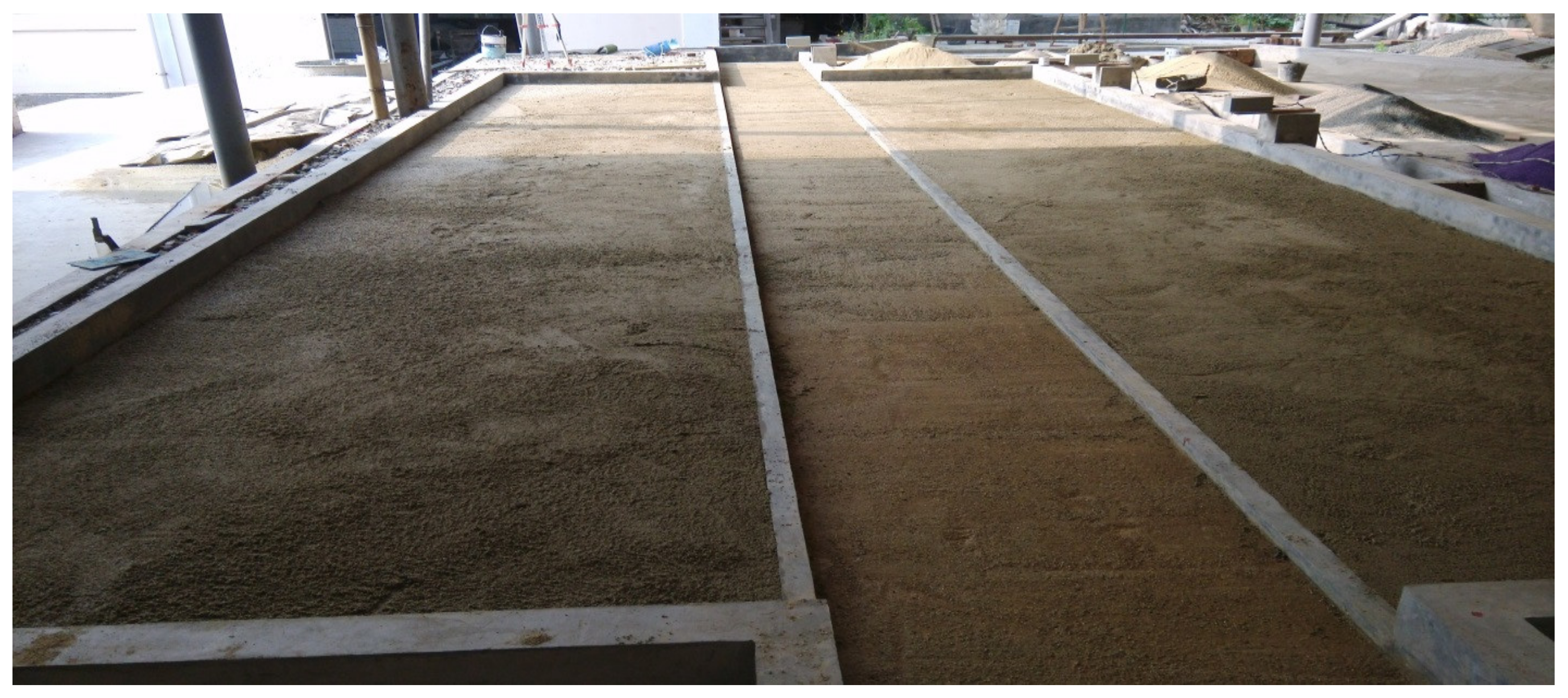
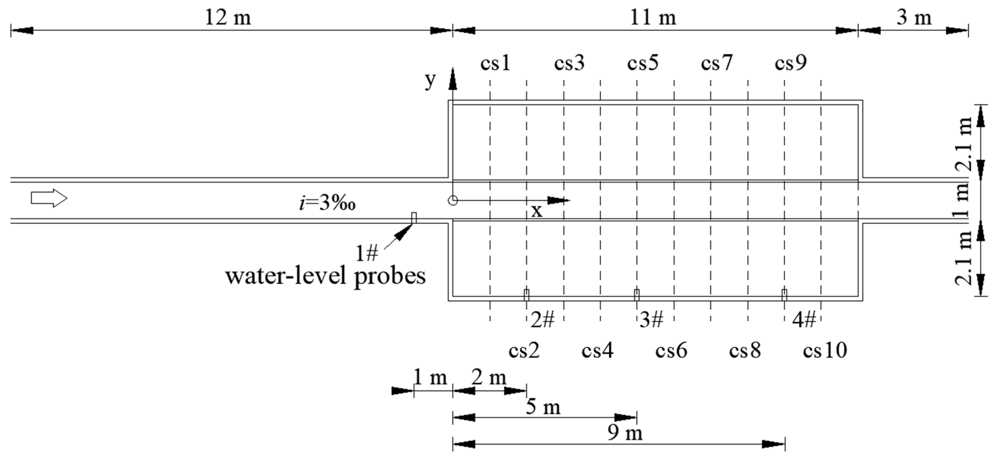
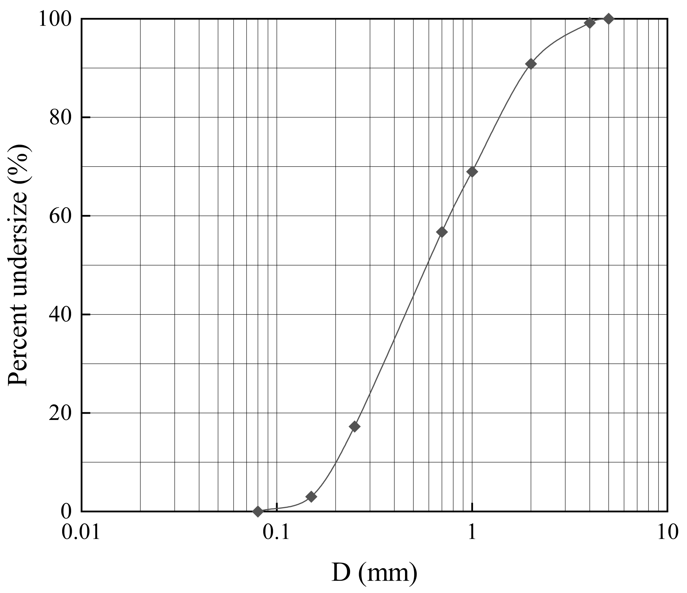
2. Experimental Setup
3. Results and Discussion
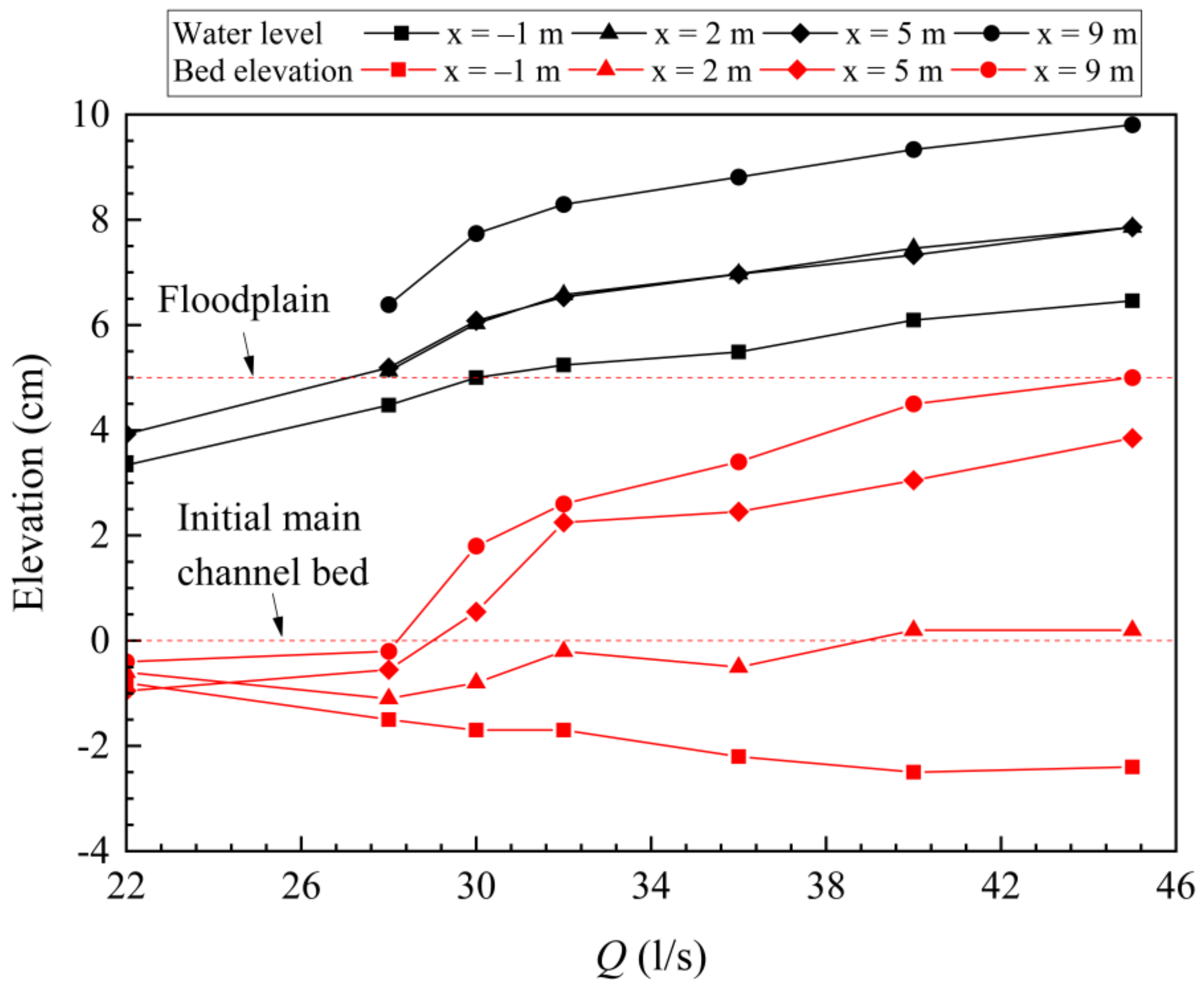
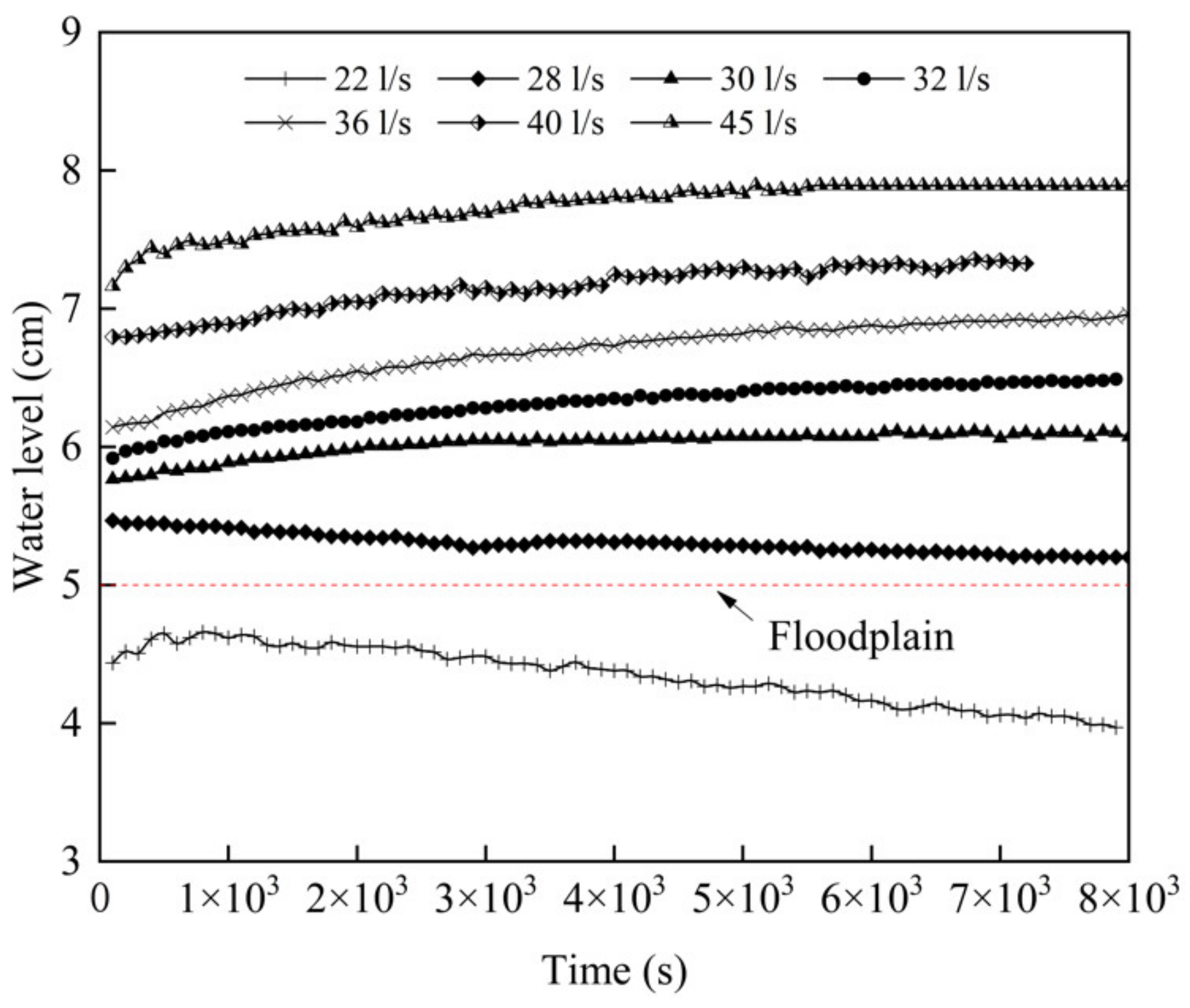
3.1. Water Level
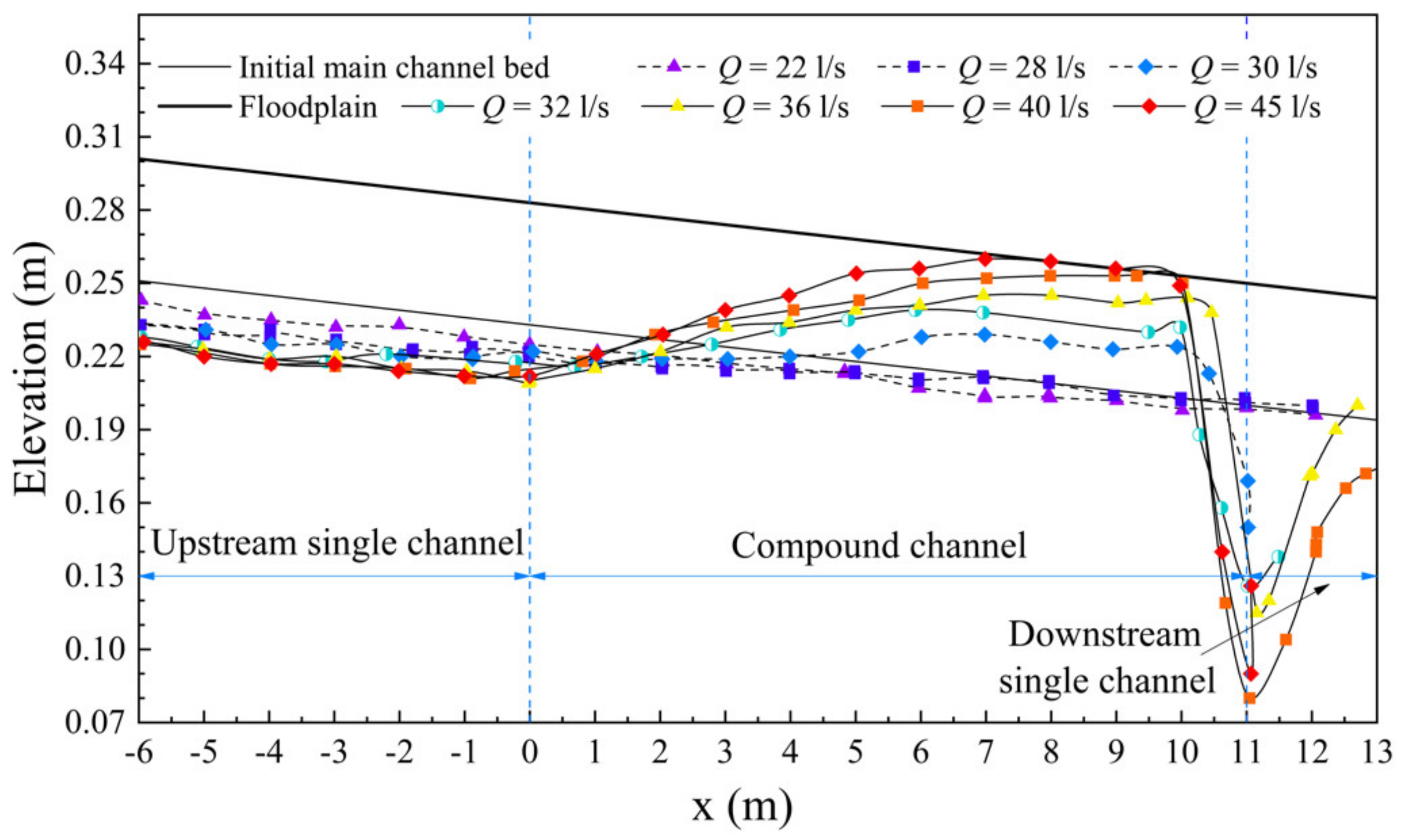
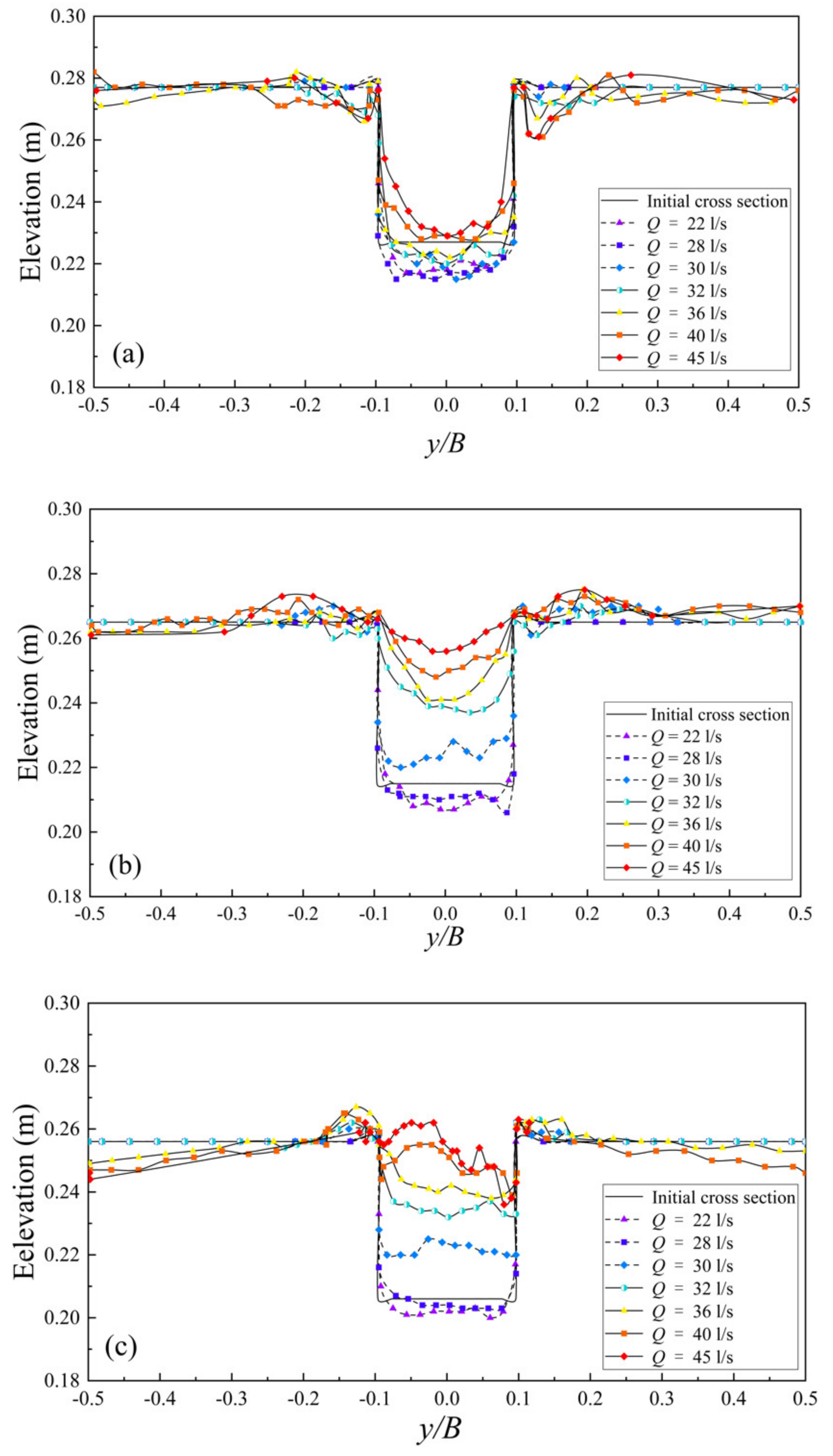
3.2. Bed Profile
4. Conclusions
Author Contributions
Funding
Acknowledgments
Conflicts of Interest
References
- Liu, X.N.; Zhou, Q.; Huang, S.; Guo, Y.K.; Liu, C. Estimation of flow direction in meandering compound channels. J. Hydrol. 2018, 556, 143–153. [Google Scholar] [CrossRef] [Green Version]
- Hu, C.H.; Ji, Z.W.; Guo, Q.C. Flow movement and sediment transport in compound channels. J. Hydraul. Res. 2010, 48, 23–32. [Google Scholar] [CrossRef] [Green Version]
- Knight, D.W.; Brown, F.; Valentine, E.; Nalluri, C.; Bathurst, J.; Benson, I.; Myers, R.; Lyness, J.; Cassells, J. The response of straight mobile bed channels to inbank and overbank flows. Proc. Inst. Civ. Eng. Water Manag. Energy 1999, 136, 211–224. [Google Scholar] [CrossRef]
- Knight, D.W. Sediment transport in rivers with overbank flow. J. Sichuan Univ. (Eng. Sci. Ed.) 2005, 1, 16–29. [Google Scholar]
- Yang, K.J.; Cao, S.Y.; Knight, D.W. Flow patterns in compound channels with vegetated floodplains. J. Hydraul. Eng. 2007, 133, 148–159. [Google Scholar] [CrossRef]
- Yang, K.; Liu, X.; Cao, S.; Huang, E. Stage-discharge prediction in compound channels. J. Hydraul. Eng. 2014, 140, 06014001. [Google Scholar] [CrossRef]
- Tominaga, A.; Nezu, I. Turbulent structure in compound open-channel flows. J. Hydraul. Eng. 1991, 117, 21–41. [Google Scholar] [CrossRef]
- Knight, D.W.; Abril, J.B. Refined calibration of a depth-averaged model for turbulent flow in a compound channel. Proc. Inst. Civ. Eng. Water Manag. Energy 1996, 118, 151–159. [Google Scholar] [CrossRef]
- Shirley, E.D.; Lopes, V.L. Normal-depth calculations in complex channel sections. J. Irrig. Drain. Eng. 1991, 117, 220–232. [Google Scholar] [CrossRef] [Green Version]
- Myers, W.R.C. Velocity and discharge in compound channels. J. Hydraul. Eng. 1987, 113, 753–766. [Google Scholar] [CrossRef]
- Stephenson, D.; Kolovopoulos, P. Effects of momentum transfer in compound channels. J. Hydraul. Eng. 1990, 116, 1512–1522. [Google Scholar] [CrossRef]
- Myers, W.R.C. Momentum transfer in a compound channel. J. Hydraul. Res. 1978, 16, 139–150. [Google Scholar] [CrossRef]
- Prinos, P.; Townsend, R.D. Comparison of methods for predicting discharge in compound open channels. Adv. Water Resour. 1984, 7, 180–187. [Google Scholar] [CrossRef]
- Wormleaton, P.R.; Allen, J.; Hadjipanos, P. Discharge assessment in compound channel flow. J. Hydraul. Div. ASCE 1982, 108, 975–994. [Google Scholar]
- Ervine, D.A.; Baird, J.I. Rating curves for rivers with overbank flow. Proc. Inst. Civ. Eng. Part 2 Res. Theory 1982, 73, 465–472. [Google Scholar] [CrossRef]
- Wormleaton, P.R.; Merrett, D.J. An improved method of calculation for steady uniform flow in prismatic main channel/floodplain sections. J. Hydraul. Res. 1990, 29, 272–276. [Google Scholar] [CrossRef]
- Wright, R.R.; Carstens, M.R. Linear momentum flux to overbank sections. J. Hydraul. Div. 1970, 99, 219–238. [Google Scholar]
- Liu, P.Q.; Dong, J.R. Hydraulic computation of steady-uniform flows in open channels with compound cross section. J. Yangtze River Sci. Res. Inst. 1995, 3, 61–66. (In Chinese) [Google Scholar]
- Ackers, P. Hydraulic design of two-stage channels. Proc. Inst. Civ. Eng. Water Manag. Energy 1992, 96, 247–257. [Google Scholar] [CrossRef]
- Ackers, P. Flow formulae for straight two-stage channels. J. Hydraul. Res. 1993, 31, 509–531. [Google Scholar] [CrossRef]
- Ackers, P. Stage-discharge functions for two-stage channels: The impact of new research. J. Inst. Water Environ. Manag. 1993, 7, 52–61. [Google Scholar] [CrossRef]
- Shiono, K.; Knight, D.W. Turbulent open-channel flows with variable depth across the channel. J. Fluid Mech. 1991, 222, 617–646. [Google Scholar] [CrossRef]
- Chen, L.; Zhan, Y.Z.; Zhou, Y.L.; Wang, M.F. Forms and functions of flow and sediment flux exchange in high sediment content overbank flow. J. Sediment Res. 1996, 45–49. (In Chinese) [Google Scholar] [CrossRef]
- Knight, D.W.; Brown, F.A. Resistance studies of overbank flow in rivers with sediment using the flood channel facility. J. Hydraul. Res. 2001, 39, 283–301. [Google Scholar] [CrossRef]
- Tang, X.N.; Knight, D.W. Sediment transport in river models with overbank flows. J. Hydraul. Eng. 2006, 132, 77–86. [Google Scholar] [CrossRef]
- Atabay, S.; Knight, D.W. 1-D modelling of conveyance, boundary shear and sediment transport in overbank flow. J. Hydraul. Res. 2006, 44, 739–754. [Google Scholar] [CrossRef]
- Karamisheva, R.D.; Lyness, J.F.; Myers, W.R.C.; Cassells, J.B.C.; O’Sullivan, J. Sediment transport formulae for compound channel flows. Proc. Inst. Civ. Eng. Water Manag. 2006, 159, 183–193. [Google Scholar] [CrossRef]
- Atabay, S.; Knight, D.W.; Seckin, G. Effects of overbank flow on fluvial sediment transport rates. Proc. Inst. Civ. Eng. Water Manag. 2005, 158, 25–34. [Google Scholar] [CrossRef]
- Melville, B.W.; Coleman, S.E. Bridge Scour; Water Resources Publication: Highlands Ranch, CO, USA, 2000. [Google Scholar]

| Test | Discharge Q (L/s) | S (‰) | D50 (mm) | Channel Width B (m) | Main Channel Width b (m) |
|---|---|---|---|---|---|
| 1 | 22 | 3 | 0.5 | 5.2 | 1 |
| 2 | 28 | 3 | 0.5 | 5.2 | 1 |
| 3 | 30 | 3 | 0.5 | 5.2 | 1 |
| 4 | 32 | 3 | 0.5 | 5.2 | 1 |
| 5 | 36 | 3 | 0.5 | 5.2 | 1 |
| 6 | 40 | 3 | 0.5 | 5.2 | 1 |
| 7 | 45 | 3 | 0.5 | 5.2 | 1 |
Publisher’s Note: MDPI stays neutral with regard to jurisdictional claims in published maps and institutional affiliations. |
© 2020 by the authors. Licensee MDPI, Basel, Switzerland. This article is an open access article distributed under the terms and conditions of the Creative Commons Attribution (CC BY) license (http://creativecommons.org/licenses/by/4.0/).
Share and Cite
Wu, W.; Wang, L.; Ma, X.; Nie, R.; Liu, X. Flow Characteristics and Bed Morphology in a Compound Channel between Two Single Channels. Water 2020, 12, 3544. https://doi.org/10.3390/w12123544
Wu W, Wang L, Ma X, Nie R, Liu X. Flow Characteristics and Bed Morphology in a Compound Channel between Two Single Channels. Water. 2020; 12(12):3544. https://doi.org/10.3390/w12123544
Chicago/Turabian StyleWu, Weiming, Lu Wang, Xudong Ma, Ruihua Nie, and Xingnian Liu. 2020. "Flow Characteristics and Bed Morphology in a Compound Channel between Two Single Channels" Water 12, no. 12: 3544. https://doi.org/10.3390/w12123544
APA StyleWu, W., Wang, L., Ma, X., Nie, R., & Liu, X. (2020). Flow Characteristics and Bed Morphology in a Compound Channel between Two Single Channels. Water, 12(12), 3544. https://doi.org/10.3390/w12123544