Article

Experimental Study on the Influence of the Transition Section in the Middle of a Continuous Bend on the Correlation of Flow Movement in the Front and Back Bends

State Key Laboratory of Water Resources and Hydropower Engineering Science, Wuhan University, Wuhan 430072, China
*
Author to whom correspondence should be addressed.
Water 2020, 12(11), 3213; https://doi.org/10.3390/w12113213
Submission received: 27 September 2020 / Revised: 12 November 2020 / Accepted: 14 November 2020 / Published: 17 November 2020
(This article belongs to the Special Issue Research on Hydraulics and River Dynamics)

Abstract

:
There exists a correlation in the flow movement between the front and back bends of a continuous bend, and the change in the transition section configuration influences this correlation. In this paper, laboratory experiments were conducted to systematically measure the three-dimensional velocity in a continuous bend with different width/depth ratios of the transition section. Based on this work, the flow movement characteristics of a continuous bend were analysed, including the circulation structure, circulation intensity and Turbulent Kinetic Energy (TKE). The flow movement correlation between the front and back bends of the continuous bend was also analysed. The influence of the width/depth ratio of the transition section on the correlation of the flow movement of the front and back bends and their relationship with discharge were explored. This research could help to elucidate the development and evolution laws of the continuous bend and provide theoretical support for flow movement, flood routing, sediment transport and riverbed evolution. It is found that in addition to the circulation structure and intensity, the TKE of the front and back bends of the continuous bend also shows a strong correlation. With increasing discharge, the correlation between the front and back bends increases, and the larger the discharge is, the greater the influence of the same amplitude of variation in the discharge on the correlation. At the same time, the larger the discharge is, the greater the influence of the same amplitude of variation in the width/depth ratio of the transition section on the correlation of the front and back bends. When the discharge is constant, the correlation between the front and back bends decreases with the decrease in the width/depth ratio of the transition section, and the smaller the width/depth ratio, the greater the influence of the same amplitude of variation in the width/depth ratio on the correlation. There is no linear relationship between the amplitudes of variation in both the discharge and width/depth ratio and the corresponding amplitude of variation in the correlation. With increasing discharge, the amplitude of variation in the correlation caused by the same amplitude of the variation in discharge slightly increases. However, there is an exponential relationship between the amplitude of variation in the width/depth ratio and the corresponding correlation. The influence of the width/depth ratio on the correlation is clearly greater than that of the discharge.

1. Introduction

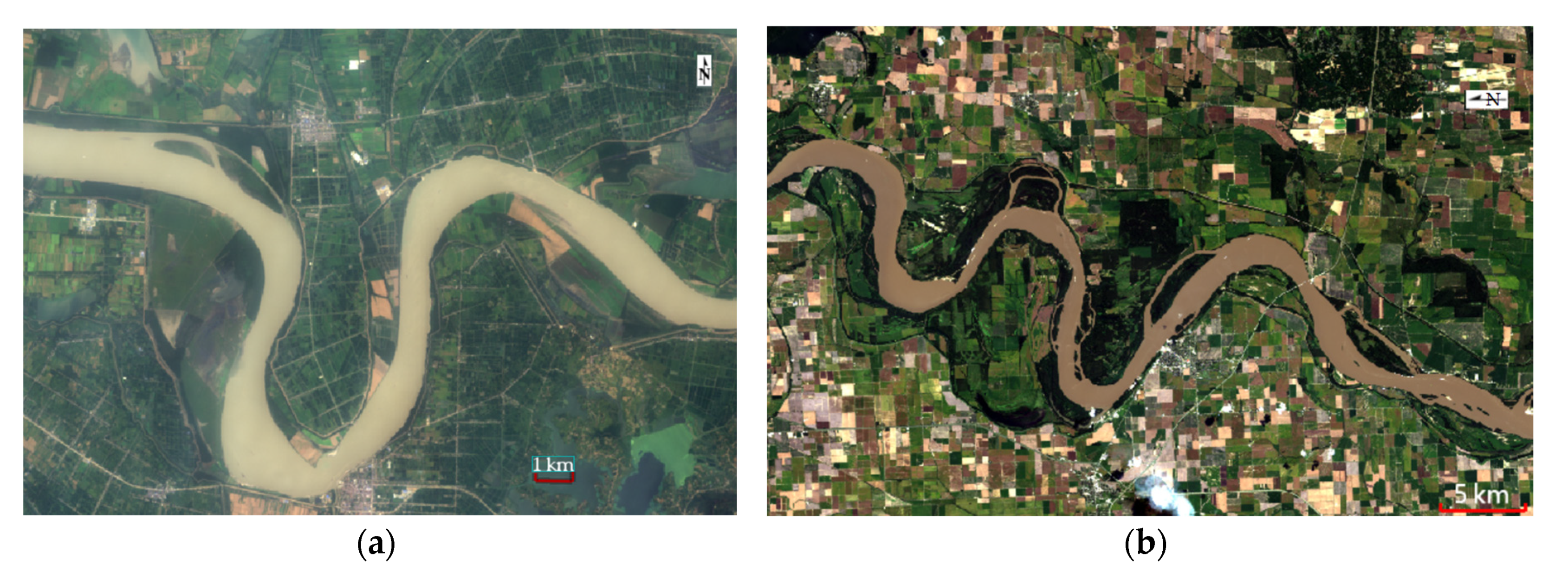
There are many continuous bends in nature; see Figure 1. Unlike single bend, the flow characteristics of any bend along a continuous bend are not only related to its own configuration and the composition of the riverbed boundary but also influenced by the upstream and downstream reaches [1,2]. In a continuous bend, a front bend, back bend and transition section function as a whole, where the front and back bends are correlated with each other through the transition section, making the flow movement characteristics in the continuous bend more complex, especially in the back bend. As early as the 1930s, Mockmore [3] noticed that the flow characteristics of the back bend in a continuous bend are influenced by the Residual Circulation of the Front Bend (RCFB). Later, both numerical simulations [4,5] and laboratory experiments [6,7] pointed out that circulation produced in the front bend could exist in the back bend, influencing flow structure such as velocity distribution [8], circulation structure [5,8,9,10] and turbulence parameters [9] in the back bend. Because of the above correlation between the “single bends” of the continuous bend, research on continuous bends is relatively difficult and has been one of the hotspots worldwide.
As the link between the front and back bends, the configuration of the transition section has an important influence on the correlation between the front and back bends of a continuous bend. At present, many scholars have carried out relevant researches. For example, from the perspective of flow characteristics, Ghanmi [11] investigated the variation in transverse velocity exiting the front bend in transition sections with different lengths by combining physical model and mathematical model experiments and pointed out that when the distance between the front and back bends is relatively small, the RCFB will extend to a certain distance in the back bend; when the length of the transition section is approximately 4R (R is the radius of the bend), the RCFB will disappear when the inlet section of the back bend is reached. If the length of the transition section continues to increase, the RCFB will completely disappear before entering the back bend. Liu [12] also pointed out that when the length of the transition section reaches 3~5 times the length of the bend reach, the influence of the front bend on the back bend is so small that it can be ignored. Hu et al. [13] analysed the position corresponding to complete attenuation and generation of the circulation structure, as well as the surface reflux in the back bend with different transition section lengths by means of mathematical model experiments and concluded that the longer the relative transition section length (L/R) is, the smaller the influence of the front bend on the back bend, but when the relative transition section length equals 0.375, the influence remains constant. Zhou et al. [14] and Zhou et al. [15] pointed out that if the length of the transition section is significantly larger than (less than) the complete attenuation length, the influence of the front bend circulation can be (cannot be) ignored. Jing and Zhao [16] studied the influence of the boundary configuration factor of the transition section of a continuous bend on the transverse gradient of the bend and found that the transverse gradient of the front bend and the transition section increased with the increase in the boundary configuration factor, while the back bend decreased in turn. From the perspective of sediment transport, Cai et al. [17] pointed out that to ensure good river channel conditions between the front and back bends and to avoid the appearance of sand ridges in the transition section, the length/width ratio of the transition section should be 1.5~4, with the most effective ratios being closer to 3. Wang et al. [18] pointed out that when the transition section between the two bends is too long or too short, a shoal easily forms in the transition section, and the most suitable length of the transition section corresponds to when the end of the circulation of the front bend can just reach the formation stage of the circulation in the back bend.
Previous studies have only investigated the influence of the length and boundary configuration of the transition section on the correlation between the front and back bends in a continuous bend [11,13,16,19], while there is a lack of studies on the influence of the width/depth ratio. The above studies focused on factors such as transverse velocity, circulation structure, circulation intensity, surface reflux and transverse slope and did not reveal the correlation of TKE and the relationship between the configuration of the transition section and the correlation. Moreover, the above studies were mostly mathematical model simulations and theoretical analyses, with regular cross-section configurations, which do not accurately represent natural riverbeds, and the reliability of the experimental results needs to be confirmed [20,21]. In summary, this paper adopts the compound cross-section flume experiment, uses an Acoustic Doppler Velocimeter (ADV) to measure the three-dimensional velocity of continuous bend at different discharges and different transition section width/depth ratios and obtains hydraulic elements that closely reflect an actual situation [22]. Based on the measured results, the correlations among the circulation structure, circulation intensity and TKE between the front and back bends of a continuous bend are analysed; moreover, the influence of the width/depth ratio of the transition section on the correlation between the front and back bends and its relationship with discharge is explored. According to the above studies, the importance of the transition section is revealed, and the flow characteristics in continuous bends are better understood.
The aims of this study were to explore the correlation between front and back bends of the continuous bend. Specifically, we will investigate the influence of the width/depth ratio of the transition section on the correlation of the flow movement of the front and back bends and their relationship with discharge. We will also compare the influence of discharge and width/depth ratio of transition section on the correlation between the front and back bends of the continuous bends, to help comprehensively understand the mechanics of flow in continuous river bends.
The above aims may help to elucidate the development and evolution laws of the continuous bend and provide theoretical support for a more comprehensive understanding of flow movement, flood routing, sediment transport and riverbed evolution in continuous bends and provide help for better numerical simulation of the continuous bend. Meanwhile, in engineering practice, a full understanding of the correlation of the front and back bends of the continuous bend and its relationship with discharge and transition section configuration can be used for more effective channel regulation and river management.

2. Experimental Setup and Methods

2.1. Design of the Experiment Flume

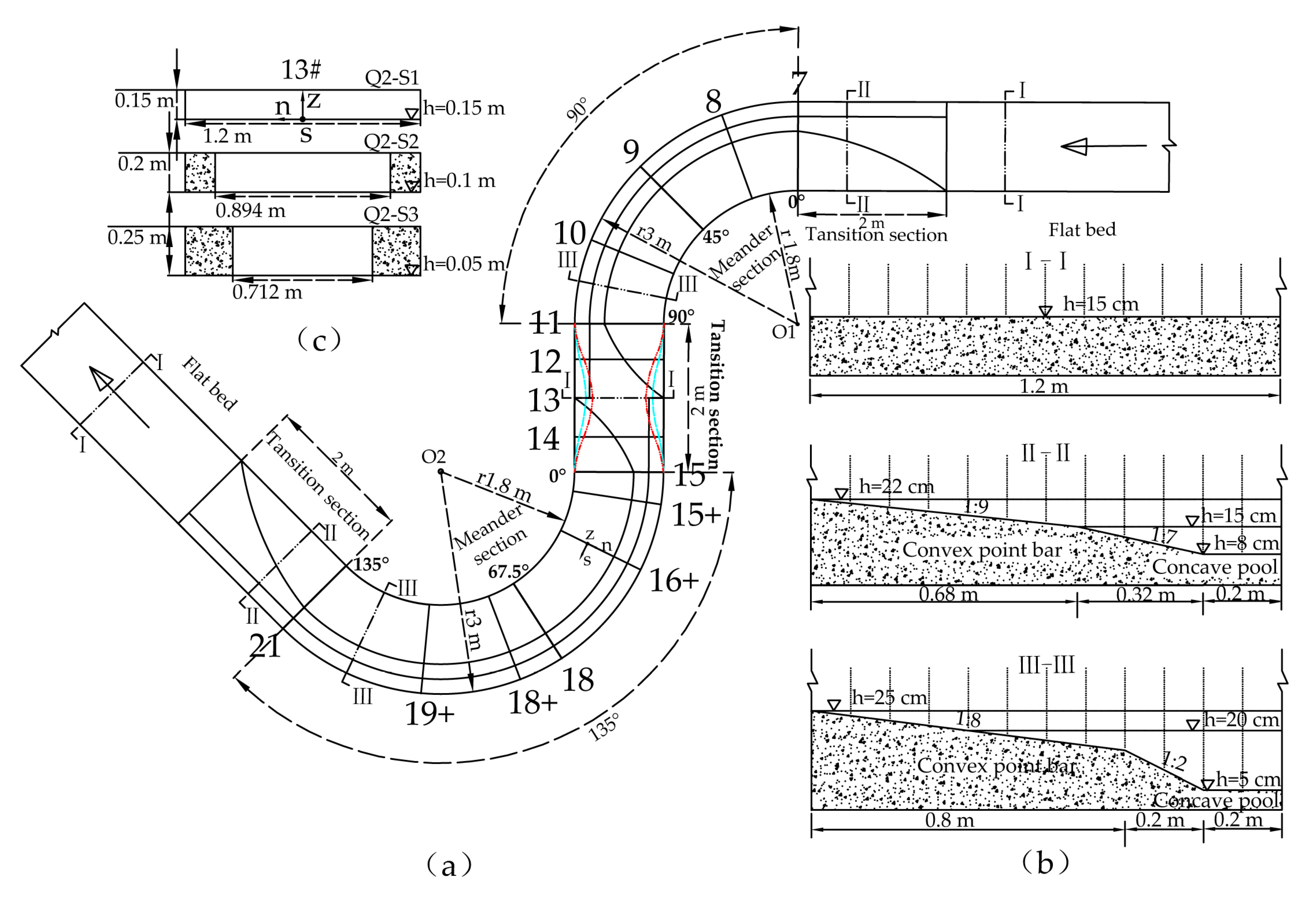
In this paper, 90° and 135° are selected as the central angles of the front and back bends of the continuous bend in the experimental flume. A 2 m long transition section is set between two bends, where the straight reach is tangent to the curved reach. The planform of the laboratory flume after generalization is shown in Figure 2a; a 7 m long straight reach is set up upstream and downstream of the continuous bend. The upstream straight reach ensures the stability of the flow entering the experiment reach, and the downstream straight reach reduces the influence of the tail gate on the flow structure. The radii of the central axes of the front and back bends are both 2.4 m, the width of the flume is 1.2 m, and the curvature ratio (r/B) is 2 [23]. If the curvature ratio is less than 2, it represents a sharp bend channel [24], so this flume can be regarded as a continuous sharp bend flume.
In Figure 2b, III-III shows the cross-section geometry of the bend flume, in which the width of the point bar is 0.8 m, with a transverse slope of 1:8. The elevation of the bar top is 0.25 m, and that of the bar bottom is 0.15 m. The concave pool is composed of a transitional slope with a width of 0.2 m linking to the point bar, with a transverse slope of 1:2, and a 0.2 m wide flat pool, with a constant elevation of 0.05 m. The straight inflow and outflow reaches and section 13# in the transition section are designed to have a horizontal bed with an elevation of 0.15 m, and their cross-section geometry is shown in I-I in Figure 2b. At the downstream end of the inflow reach and the upstream end of the outflow reach, the transition section with a length of 2 m transforms smoothly from the horizontal bed to the bar-pool geometry. The geometry of a randomly selected cross-section in this transition section is shown in II-II in Figure 2b.

2.2. Experiment and Scenario Design

The selected discharges, corresponding water levels and various hydraulic parameters are shown in Table 1. The inflow discharge is controlled by an electromagnetic flowmeter with an accuracy of 0.5%, and the discharge is controlled by adjusting the valve; the tail door is a plate-turning type, and the water level of the flume is controlled by adjusting the opening degree of the tail door. The experimental flume is made of cement plastering, which is as smooth and uniform as possible to reduce the influence of the variability in roughness on flow.
As shown in Figure 2a,c, section 13# has B1 = 1.20 m in the S1 state; in the S2 and S3 states, section 13# narrows to different degrees. After narrowing, the planform shapes of the transition sections are shown as cyan dotted lines and red dashed lines, and the corresponding widths are B2 = 0.89 m and B3 = 0.71 m, respectively. To ensure the consistency of the cross-sectional area, the transition sections of S2 and S3 are deepened accordingly.
The parameters of the three scenarios are shown in Table 1. After narrowing twice, the width/depth ratios of section 13# are significantly reduced, the variation amplitudes of Q1 are 47% and 67%, those of Q2 are 44% and 64%, and those of Q3 are 42% and 62%. The variation amplitudes of the width/depth ratio for the two scenarios at the three discharges gradually decrease with increasing discharge, but the differences are small. The variation amplitudes of the average width/depth ratio of the whole transition section for the two scenarios at the three discharges are consistent, 33% and 42.5%, respectively.
The calculation formulas of Fr and Re in the experiment are as follows:
F r = U g H
Re = U R ν
where U denotes average velocity of the cross-section, H represents average depth of the cross-section, g represents gravitational acceleration, R represents hydraulic radius, ν represents kinematic viscosity coefficient.
The Froude and Reynolds numbers of section 13# are chosen to represent the whole study area. Fr is calculated directly by Formula (1). By using the average width B and the average water depth H of the 13# section, the hydraulic radius R is obtained by the formula R = B H / ( B + 2 H ) , and Re is calculated by combining the average velocity U of the cross-section 13# and kinematic viscosity coefficient ν . The calculation results are shown in Table 1.

2.3. Data Collection and Processing

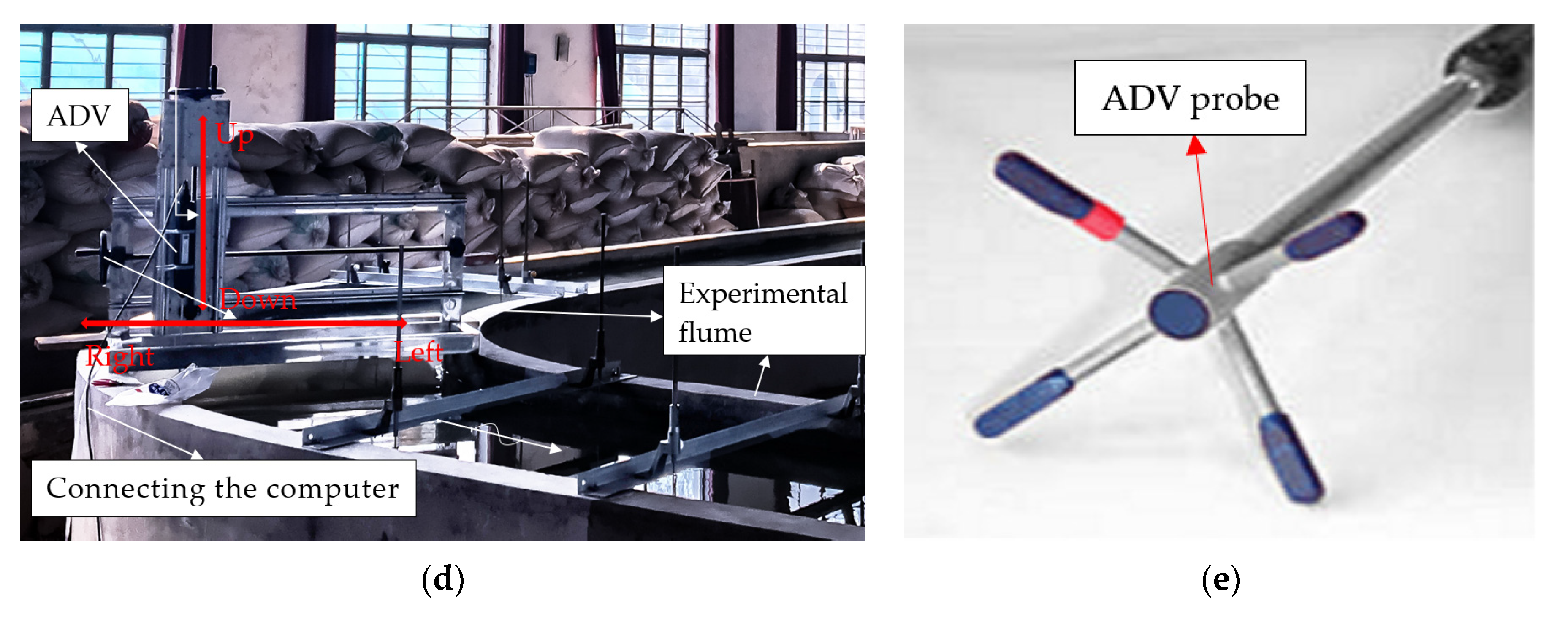
An Acoustic Doppler Velocimeter (ADV) was used to measure three-dimensional instantaneous velocity in the orthogonal curvilinear coordinate system. The position relationship between the measurement section and the orthogonal curvilinear coordinate system is shown in Figure 2a,c, where the downstream s axis coincides with the flume’s centreline, the transverse n axis points in the left direction, and the vertical z axis is upwards. The accuracy of the ADV is 0.5%. The sampling frequency was 200 Hz, and the sampling time was more than 30 s, which ensured that there were at least 6000 original velocity data points at each measuring point. The experimental setup with ADV system is installed on the model (Figure 2d), keeping the probe downward and collecting the water velocity 5 cm below the probe. ADV probe is shown in Figure 2e. When measuring, keeping the four corners of the probe on the same horizontal plane, it is ensured that the red mark of the probe is in the same direction with the downstream flow. Because the sampling volume of the probe was located 5 cm from the sensors and the probe must be completely submerged in the water, the velocity in the range of 5 cm below the surface could not be measured by the probe; considering the accuracy of the data, extrapolation processing was not carried out in this paper.
Cross-section 13# was selected as the typical section, and the accuracy assessment tests had been conducted by validating integral quantity of the normal velocity measured with ADV on cross-section 13# against the discharge measured with electromagnetic flowmeter at different discharges and conditions. The results in Table 2 showed that the error rates were all within 5%, we could infer that velocity measured with ADV was accurate enough in this experiment.
The concentration of particles in the water would influence the stability of the measurement signal. Generally, the Signal-to-Noise Ratio (SNR) must be larger than 15 to ensure data reliability [25]. When the SNR was less than 15, a small amount of plastic sand with a particle size smaller than 0.1 mm was added to the backwater system to increase the particle concentration. Both the particle size and density of the plastic sand were small, so although there was some settlement, the flow structure would not be affected.
The measurement interval of the front bend was 22.5° from section 0° to 90°, the measurement interval of the transition section was 0.5 m, and the measurement interval of the back bend was 33.75° from section 0° to 135°. The corresponding section number was shown in Figure 2a, and the additional sections 15+# and 18+# of the back bend, which were the generation and attenuation position of the circulation at some scenarios and discharges and located 11.25° downstream of sections 15# and 18#, were measured. Eleven vertical measuring lines were distributed at a horizontal interval of 10 cm across each measuring section, and 15 measuring points were arranged from bottom to top according to the intervals of 0.2 h , 0.3 h , 0.4 h , 0.5 h , 0.6 h , 0.7 h , 0.75 h , 0.84 h , 0.87 h , 0.9 h , 0.93 h , 0.96 h , 0.98 h and 1 h , respectively ( h was water depth; increasing distribution density with increasing depth). Because the measurement points across the whole cross-section were relatively sparse, interpolation processing was carried out before the circulation structure, intensity and turbulence kinetic energy experimental results were presented. The inverse distance weight interpolation method was used for interpolation, and the cross-sectional distribution map was drawn using the interpolation results.
The ADV may have some peaks caused by Doppler noise and Doppler signal aliasing in the measured velocity series. These peaks may be due to the measured velocity exceeding the set range of measured velocity or affected by the reflection of the previously transmitted signal. All of these phenomena will lead to the distortion of velocity measurement [26,27]. Therefore, it is necessary to denoise the velocity time series, and the phase space threshold processing method with threshold change is used to identify peak values in the velocity series. Then, the points before and after the peak values are replaced by polynomials.

3. Results and Discussion

3.1. Analysis of the Circulation Structure

In bends, due to the combined action of centrifugal force and hydrostatic pressure, surface water flows to the concave bank, bottom water flows to the convex bank and projection on cross-section forms circulation. In the size of the circulation, the transverse or vertical velocity is always larger than zero.
In typical cross-sections, the time-averaged velocity vector field was synthesized by using the transverse and vertical time-averaged velocities, and the transverse circulation structure was obtained by connecting the vectors with the streamline. The circulation structure here represents the distribution shape and size of the circulation on the n, z coordinate plane. Because the flume adopts a complex cross-section shape that is closer to the actual river channel, the main circulation structure in the bend is mostly narrow, exhibiting an irregular ellipse as the cross-section configuration, which is different from regular rectangular or trapezoidal channels.
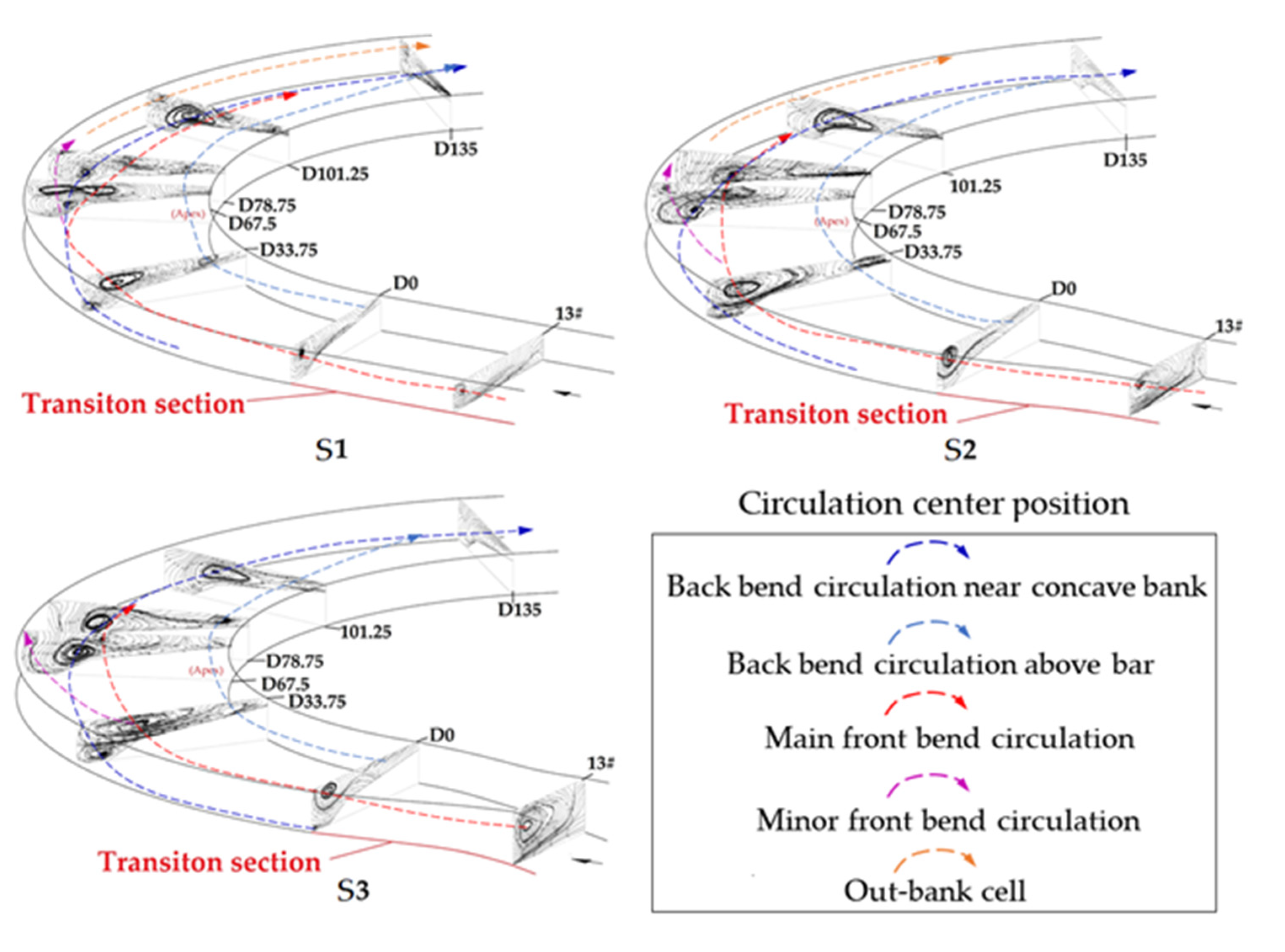
Figure 3 is a three-dimensional view of the variation in the circulation structure along the continuous bend at Q3. As shown in Figure 3, the streamline at the inlet section of the front bend begins to slightly bend, and there are signs of circulation generation. Then, a single clockwise transverse circulation is generated and gradually developed along the channel. At the outlet section, the circulation structure occupies the whole section. It can be seen from the red dotted line of the circulation centre position, the circulation centre gradually shifts from the bottom to the middle of the water body. In the transition section, we also observe a single clockwise circulation structure; however, the size is reduced, and the circulation centre is located closer to the left bank.
In the back bend channel, a single clockwise circulation can be seen at the inlet section. Since transverse circulation cannot be produced without centrifugal force, the clockwise circulation structure at the transition section and the inlet section are all the RCFB. The size of the RCFB decreases gradually along the channel, and the circulation structure is divided into two parts at the apex of the bend: the part moving to the surface of the concave bank and the part moving to the centre of the river channel. The RCFB near the concave bank is consumed by the Circulation of the Back Bend (CBB), approaching complete attenuation near 78.75° (purple dotted line), while the RCFB in the central area exists until close to the outlet of the back bend (red and orange dotted line). It should be noted that the very weak clockwise circulation structure near the concave bank gradually increases. Fariba and Alireza [28] found that the centrifugal force and cross-stream turbulent shear stress are main driving forces of near bank circulations and such conditions do exist near the concave bank. Combining the observed changes in the circulation structure along the channel, it can be inferred that this circulation is an “out-bank cell” (orange dotted line). After entering the back bend, an anticlockwise circulation structure begins to form near the bed of the concave bank (dark blue dotted line), and then an anticlockwise circulation structure forms above the convex point bar (blue dotted line). Along the channel, the two CBBs develop gradually, with the circulation in the concave pool being dominant. Afterwards, the two CBBs gradually merge together. In the back bend, a single circulation model is no longer applicable; two or more circulation structures with different vortex directions coexist, and the circulations in different directions squeeze each other, resulting in an irregular circulation structure.
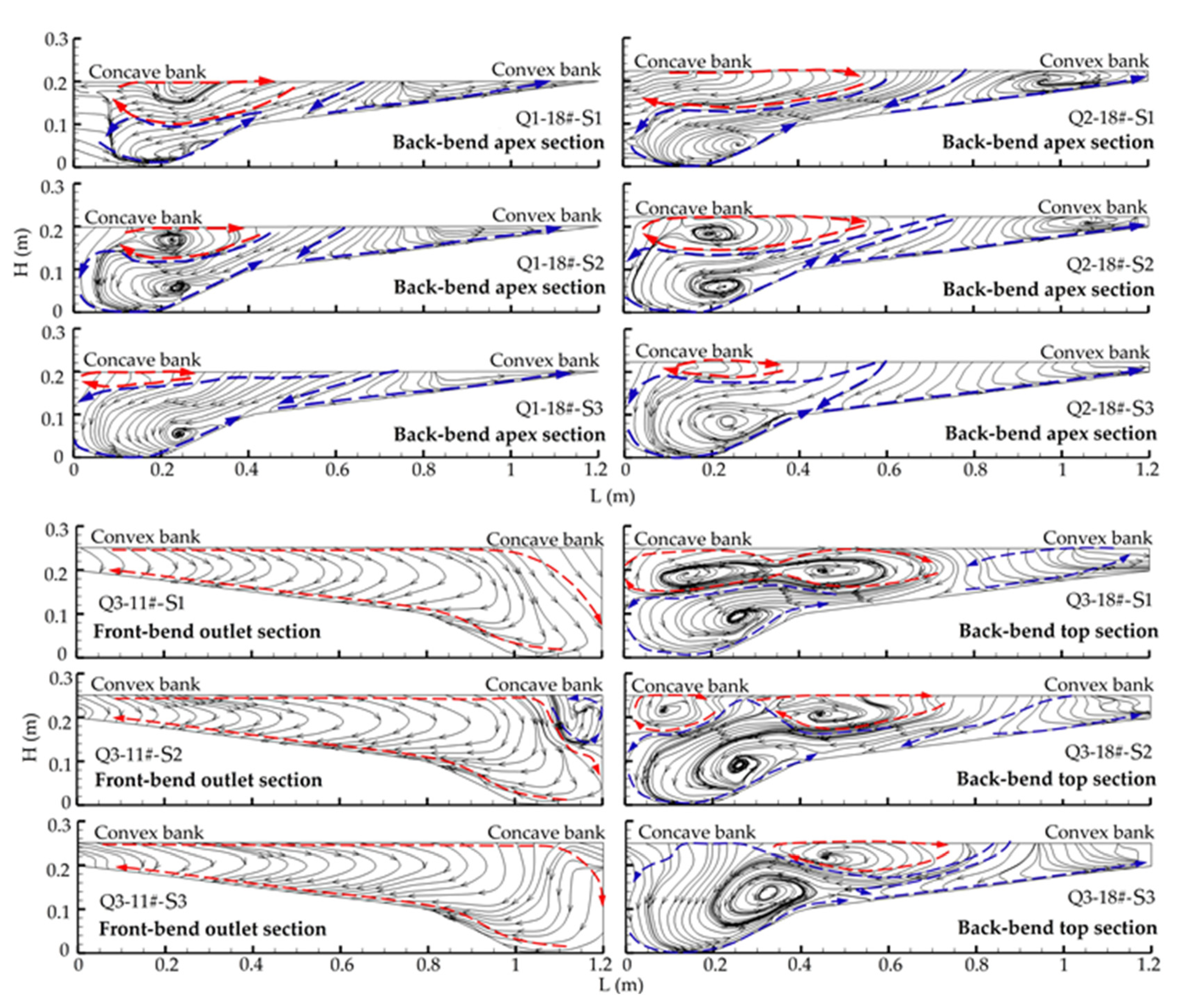
Typical sections are selected to analyse the influence of changes in the width/depth ratio on the circulation structure under different scenarios and discharges. As shown in Figure 4, with the decrease in the width/depth ratio of the transition section, at Q3, the circulation structure in the outlet section of the front bend changes little and is only slightly different in the upper part of the water body near the concave bank. However, at the three discharges, the circulation structure distribution at the apex section of the back bend all changes greatly. Especially at Q3, the size of the clockwise circulation structure decreases gradually and is divided into two parts, the component on the concave bank side gradually disappears; the size of the counterclockwise circulation structure gradually increases, and the two circulations gradually approach each other, nearly merging at S3. At other discharges, the RCFB at the apex section of the back bend decreases gradually, the CBB increases gradually.
To understand the change in the structure of the back bend more clearly, circulation structure distribution at typical cross-sections along the back bend in different scenarios is shown in Figure 5. Two or more circulation structures with different vortex directions coexist along the back bend in different scenarios. With the decrease in the width/depth ratio of the transition section, the size of the RCFB decreases gradually at the same cross-section, and minor RCFB rarely exists at cross-section 67.5° and either as main RCFB at cross-section 78.75° in S3. Meanwhile, the size of the CBB increased gradually at the same cross-section, and an anticlockwise circulation appears at the inlet section of the back bend at S3. There are no clockwise circulations near concave bank water surface at S2 and S3.
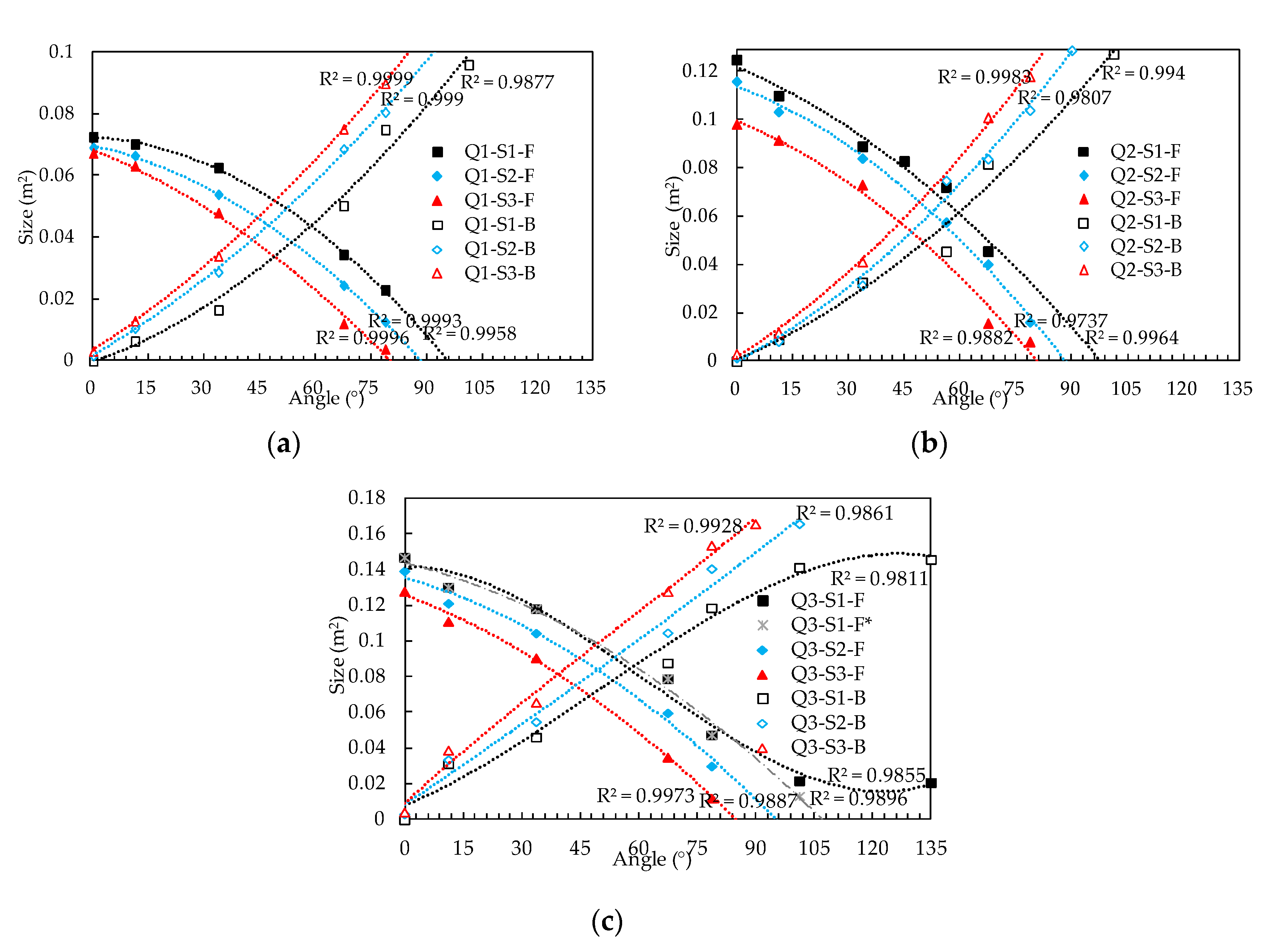
The changes in the size of the two kinds of circulation structures along the channel are analysed for different discharges and different scenarios (the CBB includes two parts, one in the concave pool and another above the convex point bar). To perform a more accurate statistical analysis of the circulation structure size, a cross-section is divided into grids with a maximum spacing of 1 cm. After interpolation, velocity vectors are plotted in each grid to identify the range of circulation. The statistical size is the size within the outer contour of the cross-section circulation; if the grid is within the range of circulation, its size is added to the circulation structure size. The changes in the size of the two kinds of circulation structures along the channel are plotted, and then, the trend lines are fitted, as shown in Figure 6. The location information of the key changes in the two circulation structures are given in Table 3.
As shown in Figure 6 and Table 3, at Q3~S1, the size of the structure of the RCFB in the back bend decreases gradually along the channel, while the size of the CBB increases. The size of the two kinds of circulation structures has the same intensity at approximately 59°. The trend near the outlet of the back bend has a large variation amplitude, which is mainly influenced by the abovementioned “out-bank cell”. The grey dotted line in the figure is the trend line after removing the “out-bank cell”. According to its intersection with the abscissa, the position corresponding to the complete attenuation of the RCFB can be deduced. The change in the circulation structure size at other discharges are similar to that of Q3, which also shows that the size of the two kinds of circulation structures increases and decreases along the channel, respectively, but there is no “out-bank cell” near the back bend outlet, and the trend is clearer. The positions where the intensities of the two circulation structures are equal are slightly different at different discharges (see Figure 6a,b).
It can be seen that the size of the two kinds of circulation structures varied with width/depth ratio of the transition section, under different conditions with the same discharge. The size of the RCFB decreases considerably at the inlet section of the back bend and then decreases downstream at the same position, and the complete attenuation position of the RCFB advances gradually. The generation position of the CBB also advances gradually with increasing size. The position where the intensities of the two circulation structures are equivalent clearly advances with decreasing width/depth ratio (see Table 3).

3.2. Analysis of Circulation Intensity

To quantitatively analyse the variation in the circulation on the typical section in the continuous bend, the intensity of the circulation is calculated. In this paper, circulation is regarded as the current rotating around a central point, and vorticity is used as an index to measure the circulation intensity. The vorticity field (three vorticity components) is determined based on the velocity flow field; the calculation formula is as follows [29,30,31,32]:
ω s = w n v z
where ω s is vorticity in downstream direction, v and w are the transverse and vertical components of velocity. After dimensionless treatment, ω s H / U , the contour map of the circulation intensity distribution in a typical section of a continuous bend was drawn, in which a negative value represents clockwise circulation, a positive value represents anticlockwise circulation, and the 0 contour line represents the boundary line between the two kinds of circulations, which is used to analyse the change in the distribution size of the two kinds of circulations.
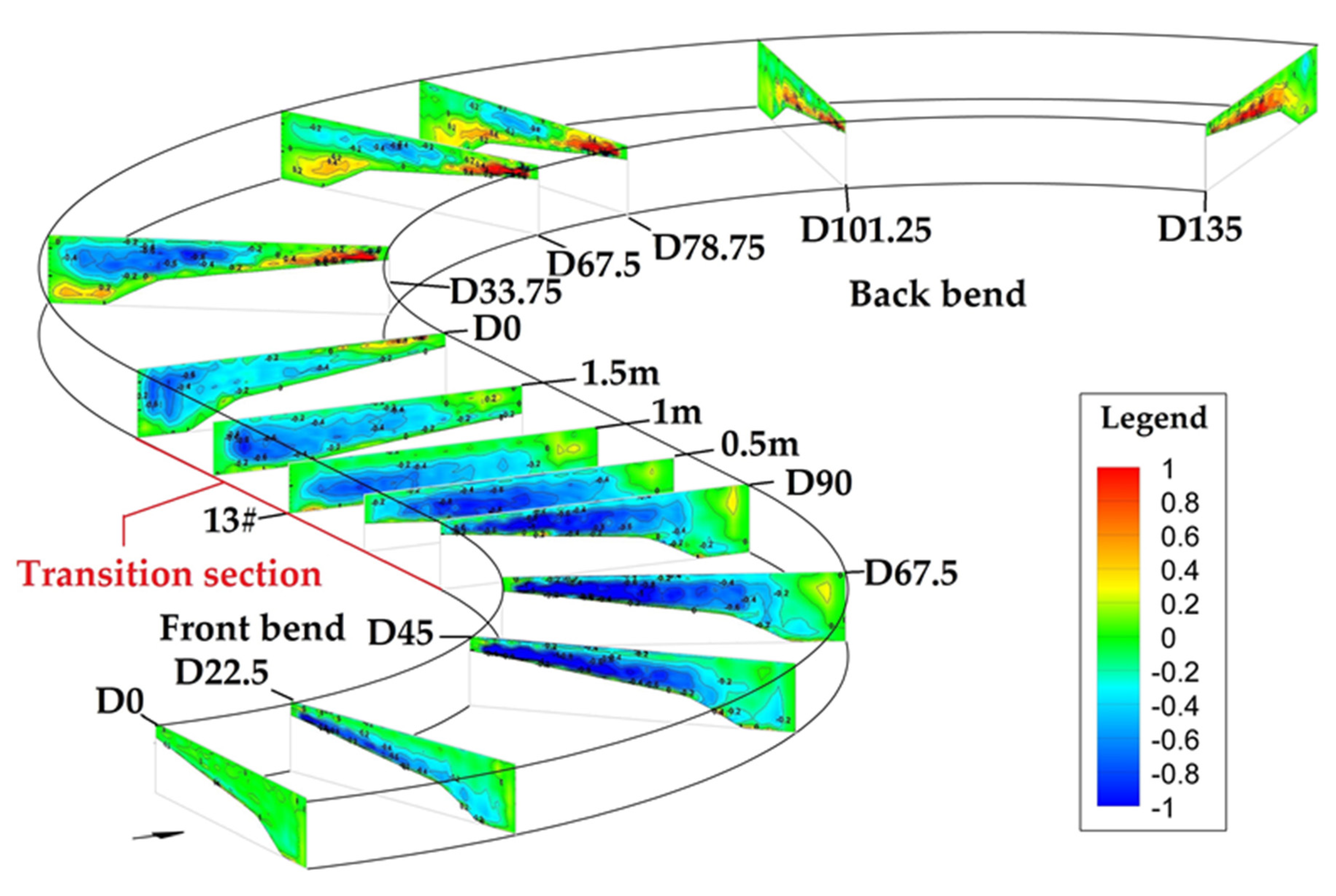
Figure 7 shows a three-dimensional view of the distribution of circulation intensity along the continuous bend with Q3. Combined with the analysis of circulation structure, this figure shows that clockwise circulation gradually occurs in the front bend, and the circulation intensity and size increase gradually along the channel, reaching a maximum value near 67.5°; there is no obvious decline in the circulation intensity until the exit of the bend. A small area of positive values appears near the concave bank of the front bend exit, which may indicate the formation of the “out-bank cell”, but no circulation structure is formed (see Figure 4). In the transition section, the clockwise circulation is still easily observable, but the intensity, especially the strong circulation intensity, decreases greatly ( ω s H / U > 0.6).
The size of the clockwise circulation at the inlet section of the back bend is still large, almost occupying the whole section. Although the size of the weak circulation intensity decreases to some extent, the size of the strong circulation intensity increases considerably at the 33.75° section, and the overall circulation intensity increases. The strong and weak circulation intensities both decrease rapidly below this section. Although there is sign of anticlockwise circulation at the bottom of the concave pool at the inlet section of the back bend, the formation of the anticlockwise circulation structure does not begin until the section of 11.25° (15+#), after which it develops gradually along the channel, and the intensity and size of the circulation increase gradually. After that, the two anticlockwise circulations merge together, and the circulation intensity centre moves to the middle of the channel.
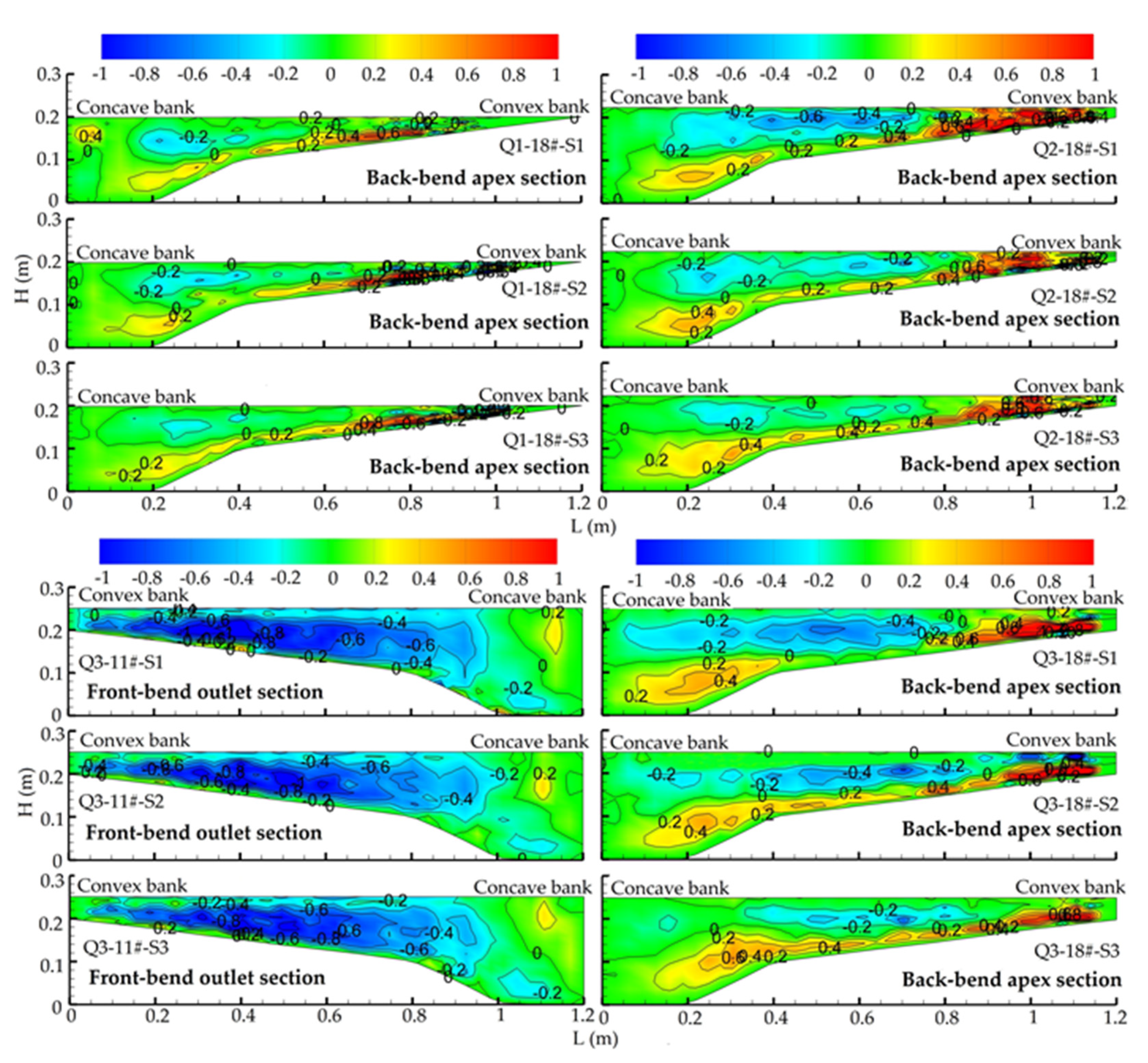
The sections of the front bend outlet and back bend apex were selected to analyse the variation in circulation intensity at the same time under different scenarios and different discharges. As shown in Figure 8, at Q3 and all three scenarios, the circulation intensity at the outlet section of the front bend weakens slightly, and the left and right sides of the main circulation area reduce slightly, but the overall change is not obvious; however, the circulation intensity and size at the apex section of the back bend change more obviously. With the decrease in the width/depth ratio of the transition section, the clockwise circulation intensity and size gradually decrease, while the counterclockwise circulation intensity and size gradually increase correspondingly. At other discharges, there is an obvious RCFB in the back bend, and the intensity of the CBB is influenced by the front bend; with the decrease in the width/depth ratio of the transition section, the change laws are the same as Q3.
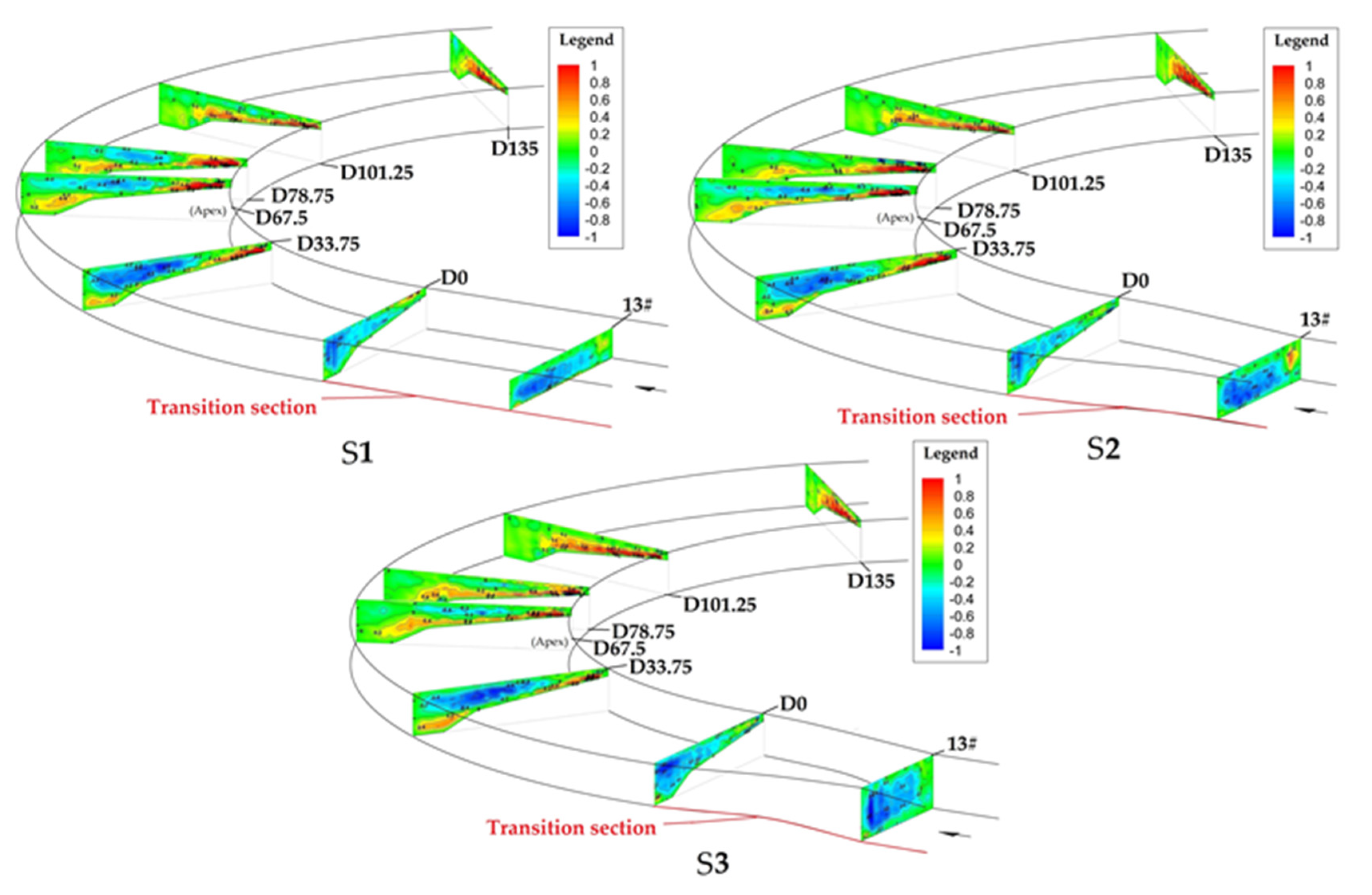
To show the variation in the circulation intensity of the back bend more clearly, circulation intensity distribution of typical cross-sections along the back bend at different scenarios under typical discharge is given in Figure 9. As figure shows, in different scenarios, two kinds of circulation intensity coexist. With the decrease in the width/depth ratio of the transition section, before the cross-section 33.75°, the intensity of the RCFB increases gradually at the same cross-section; then, after this section, all decrease rapidly. A positive intensity circulation appears at the inlet section of the back bend at S3. There are no negative intensity circulations near concave bank water surface at S2 and S3.
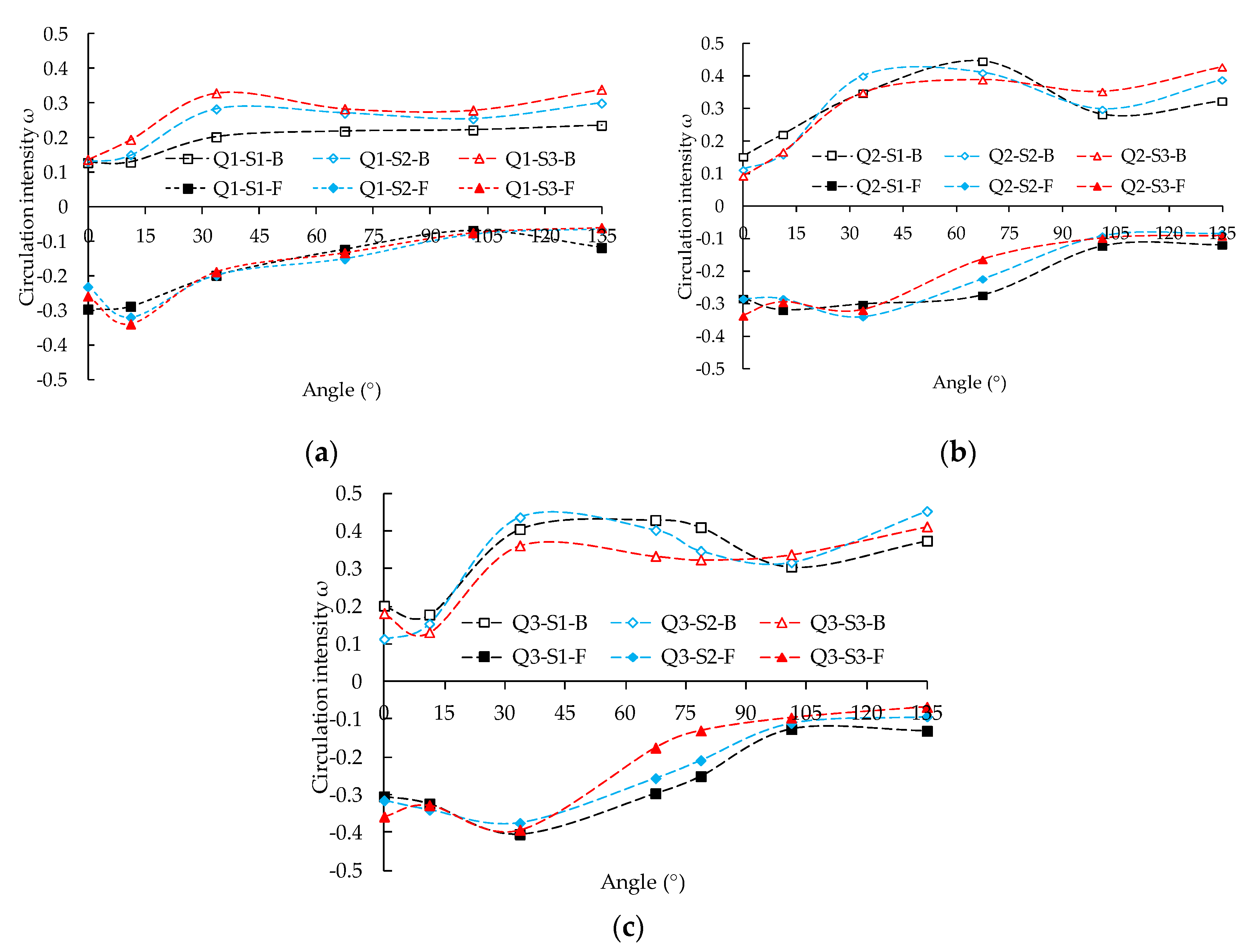
Figure 10 shows the variation in the two circulation intensities along the back bend for different discharges and scenarios. At Q3~S1, the intensity of the RCFB increases slightly near the entrance of the back bend and then decreases, with a small amplitude of fluctuation; however, the intensity of the CBB increases abruptly near the entrance and then changes slowly, weakening near the exit of the back bend, with a larger amplitude of fluctuation. The variation in circulation intensity at Q2~S1 is similar to that at Q3, but the variation in the intensity of the RCFB in the forward half of the back bend is not obvious, while at Q1~S1, the intensity of the RCFB is mainly reduced, and the intensity of the CBB mainly increases without fluctuating.
For the same discharge, with the decrease in the width/depth ratio of the transition section, the results of Q2 and Q3 show that the intensity of the RCFB weakens; while the intensity of the CBB changes only slightly, its fluctuation amplitude decreases greatly. In Q1, the intensity of the RCFB changes little, but the intensity of the CBB increases gradually.
At a fixed width/depth ratio, with increasing discharge, the intensity of the RCFB in the back bend gradually increases. The fluctuation of turbulence intensity in the back bend increases, with the distribution becoming more complex.

3.3. Analysis of Turbulent Kinetic Energy

Turbulent kinetic energy is a physical quantity that characterizes the degree of fluid turbulence. The magnitude of turbulent kinetic energy can reflect the intensity of fluid turbulence, the degree of fluid collision and friction. To calculate the TKE of each typical section along the continuous bend, the following calculation formula is employed:
k = 1 2 ( u 2 ¯ + v 2 ¯ + w 2 ¯ )
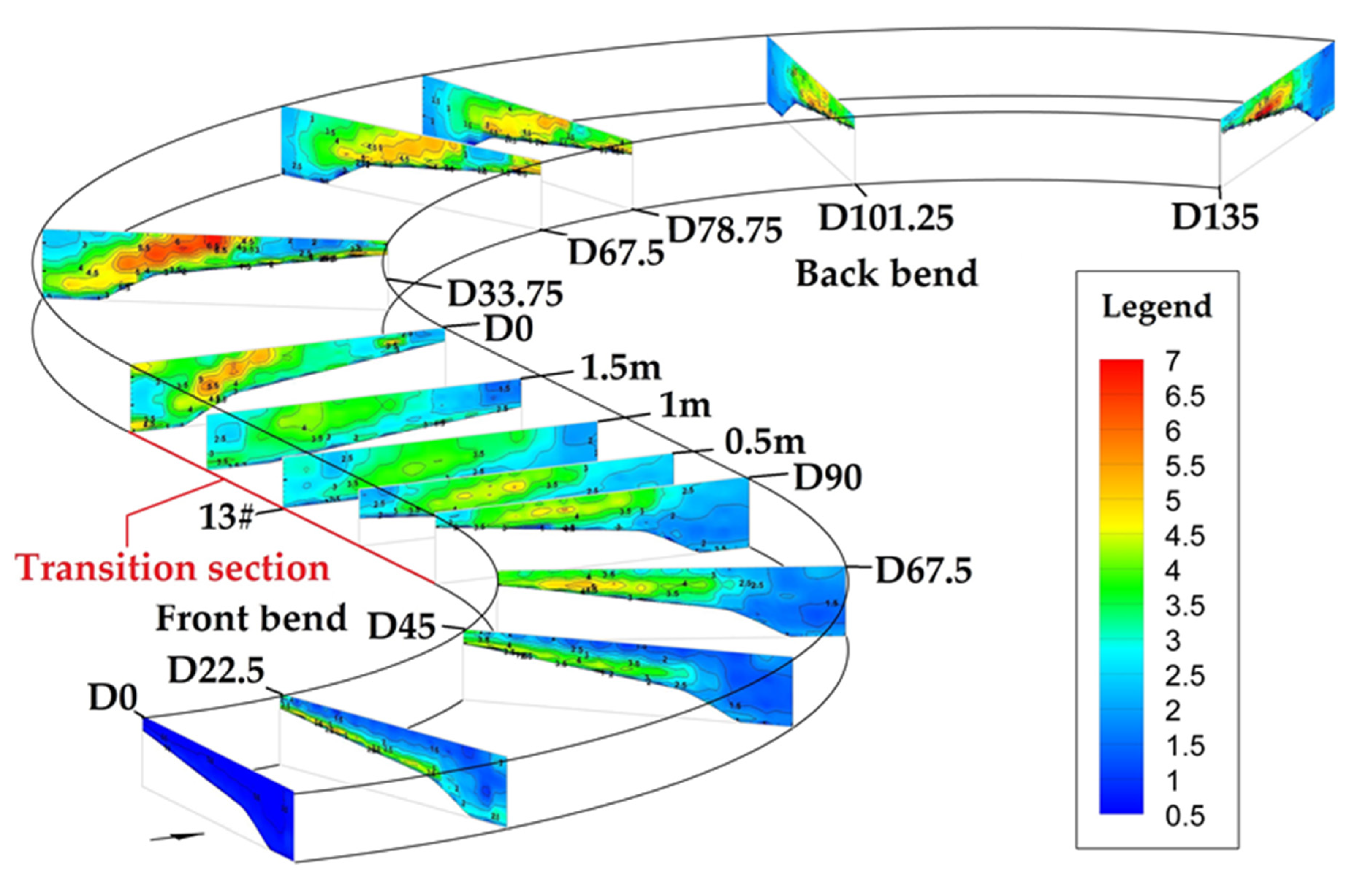
where u , v and w are the longitudinal, transverse and vertical turbulence velocity, respectively; u 2 ¯ , v 2 ¯ and w 2 ¯ are the longitudinal, transverse and vertical average turbulence intensity, respectively. The TKE distribution diagram of the typical sections along the continuous bend at Q3 is drawn in Figure 11.
As shown in Figure 11, the TKE in the front bend is divided into two parts, namely, the high-TKE area (6 > k ≥ 4.5) and the low-TKE area (k < 4.5). The results show that the TKE at the inlet section of the front bend is low and then increases gradually along the channel, with the area of high TKE appearing gradually. The high TKE reaches a maximum near 67.5° and then decreases slightly, while the low TKE increases along the channel. In the transition section, the high TKE disappears, and the low TKE increases slightly.
The amplitude of the variation in the distribution of the TKE in the back bend is larger than that in the front bend, with a very high TKE (k ≥ 6). In the middle part of the flume (0.2–0.9 m), the area of high TKE appears in the upper part of the middle part of the flume at the inlet section, and the overall TKE is relatively high. After that, the TKE in this part of the water body increases greatly, reaching a very high TKE, and then decreases gradually until the areas of very high TKE and high TKE disappear. Correspondingly, the TKE increases gradually in the concave pool; the high-TKE area forms and expands gradually in the lower part of the water body, gradually approaches the middle part of the flume, and remains close to the bed surface. At the same time, with the increase in the TKE, the area of very high TKE slowly forms and then occupies the dominant position. With the area of very high TKE approaching the middle of the flume, the TKE in the concave pool decreases greatly.
As shown in Figure 12, at three scenarios, the high TKE enters the transition section with the flow after exiting the front bend; although the high TKE decreases along the channel, the flow into the back bend still carries a high residual TKE, and after entering the back bend, it experiences rapidly increases. After that, the residual TKE of the front bend begins to be consumed, the back bend begins to produce TKE, which gradually develops along the channel, and the phenomenon of double peaks coexisting in the middle and back reaches of the back bend arises. With the decrease in the width/depth ratio of the transition section, before the cross-section 33.75°, the TKE all increases relative to S1 at the same cross-section; then after this section, the TKE in the concave pool decreases gradually along the way, but the TKE above the convex point bar decreases firstly gradually and then increases relative to S1 at the same cross-section.
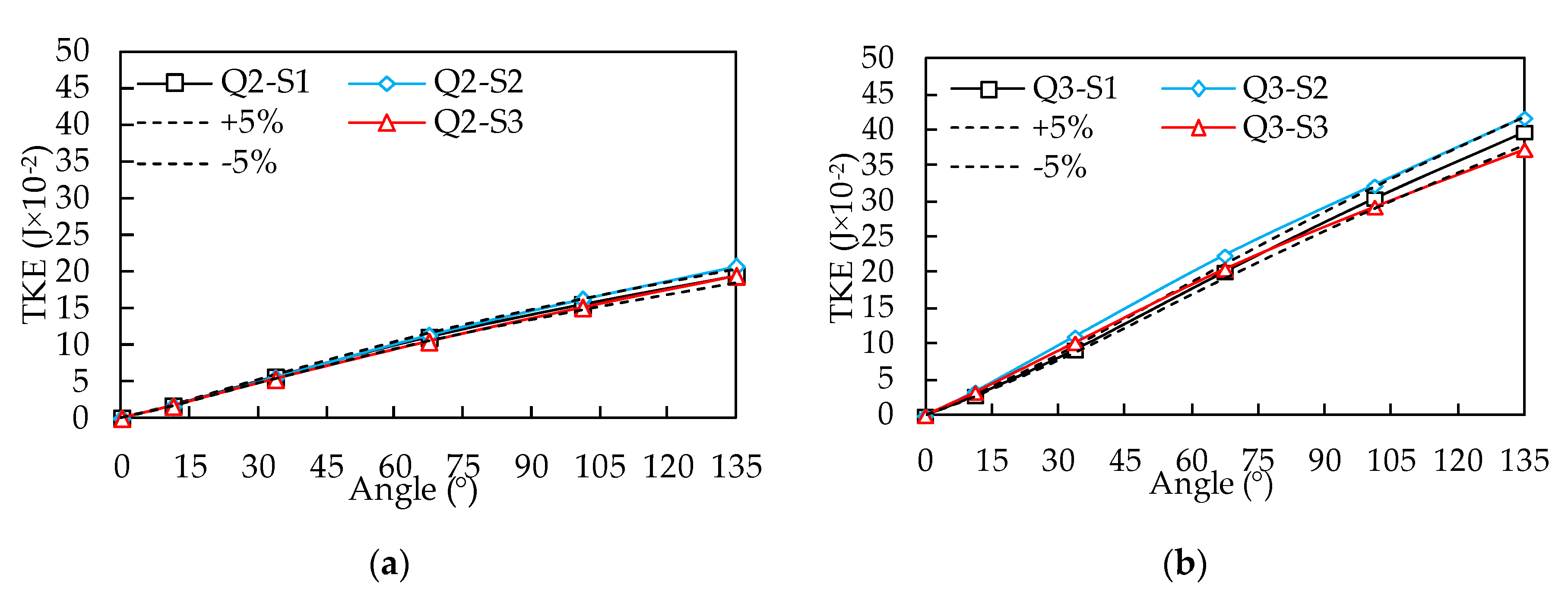
Figure 12 shows that the TKE distribution of the back bend is more complex. It is not easy to distinguish the residual TKE of the front bend from that generated by the back bend, and because the TKE is a field concept and a single section is not representative, the total TKE of the whole water body in the back bend is calculated. As shown in Figure 13, according to the change in the total TKE slope along the back bend, at the same discharge, with different width/depth ratios of the transition section, the distribution of the TKE along the back bend water body changes, but the overall change is small. The total TKE shows the same law, increasing slightly at S2 and decreasing slightly at S3, but the overall change is small, with a variation amplitude of approximately 5%. Comparing the results of different discharges under the same conditions, it is found that the greater the discharge is, the greater the amplitude of the variation in the TKE distribution, and the greater the total TKE.

3.4. Discussion

In this paper, the correlation between the front and back bends of a continuous bend is mainly revealed by their interaction. However, the analysis of the circulation structure, intensity and distribution of TKE along the continuous bend shows that the influence of the back bend on the front bend is relatively small and not easy to reflect [33], so it is usually not the focus of attention. Moreover, van der Meer et al. [34] and Lanzoni and Seminara [35] have shown that for an open channel with B/H < 10, the influence of a change in the downstream riverbed morphology will not extend upstream; the B/H ratios corresponding to all the scenarios in this paper are less than 10. Therefore, this paper mainly discusses the influence of the front bend on the back bend and the correlation reflected from this and explores the influence of the width/depth ratio of the transition section on the correlation between the front and back bends. Here, the correlation characterizes the degree of the influence of the front bend on the back bend, including the influence on circulation structure, circulation intensity and TKE. The greater the degree of influence, the stronger the correlation.
As the results show, when comparing the circulation structures of the front and back bends, there is only one single clockwise circulation in the front bend, and the configuration of the circulation structure is relatively regular. However, in the back bend, two or more circulation structures with different vortex directions coexist, with irregular circulation structure, which is similar to the previous results [22,36]; the circulation structure in the back bend is clearly more complex. The same as the circulation structure, the circulation intensity in the back bend is also clearly more complex. If the back bend is not influenced by the front bend, the evolution law of the circulation intensity of the back bend should be similar to that of the front bend and close to the maximum value near 67.5°. However, the development of the CBB is obviously restrained by the front bend, and the circulation intensity does not reach the maximum value, even at the outlet of the back bend. At the same time, the overall TKE along the back bend is larger, the areas of high TKE and very high TKE are clearly formed, the very high TKE region alternates along the channel, and the TKE distribution in the water body is more complex. The main reason for this phenomenon is the existence of residual TKE carried by the flow into the back bend.
Thus, it can be seen that due to the existence of the front bend and the short length of the transition section, the flow in the back bend carries the RCFB and TKE, which makes the distribution of the circulation structure, intensity and TKE of the back bend more complex, and makes the circulation intensity of the CBB smaller and total TKE greater than that of the front bend (single bend). It can be seen that the presence of the front bend will change the flow characteristics of the back bend. This finding is consistent with the results of Xiao et al. [37] and Moncho-Esteve et al. [38]. In addition to the circulation structure and intensity, it can also be seen that there is a strong correlation of the TKE between the front and back bends of the continuous bend.
Comparing different discharges under the same scenarios, it can be seen that with the increase in the discharge, the complete attenuation position of the RCFB gradually moves backwards. The distance of the influence of the front bend on the back bend increases. The intensity of the RCFB in the back bend gradually increases, with the distribution becoming more complex. The greater the amplitude of the variation in the TKE distribution is, the stronger the correlation becomes.
At Q3-S1, the structure of RCFB is continuously consumed when it passes through the transition section and enters the back bend, which is similar to the results of Bryk [25]. Previous studies have indicated that it takes a long distance for the circulation out of the front bend to completely disappear [39,40]. In this study, the complete attenuation position is at approximately 108°. However, according to the decline formula of the out-of-bend circulation presented in previous studies [39], the calculated decay distance is far beyond this length. The main reason for this finding is that the generation of the CBB and the opposite riverbed topography accelerate the decline in the RCFB. It can be seen that the circulations with the opposite vortex directions consume each other in the back bend. However, due to continuous power input, the CBB develops gradually, so the sizes of the two kinds of circulations show decreasing and increasing trends, respectively. The size and intensity of the RCFB decreases gradually, while those of the CBB increases gradually. The intensities of the two kinds of circulations are equivalent at approximately 60°. However, Rui [41] found that the intensities of these two kinds of circulations are equivalent at the outlet of the back bend (90°); the above difference is mainly due to the influence of the transition section, which weakens the front-bend factor before entering the back bend.
As the results shown, the intensity of the RCFB and the TKE all increase firstly (before 33.75°) in the inlet reach of the back bend, then decrease after 33.75°. Termini and Piraino [42] also found that the intensity of the RCFB increases firstly, then it decreases in intensity and disappears at crossover-section downstream, but it increases before the bend apex. However, Abad and Garcia [7,9] found that the intensity of the RCFB keeps increasing.
Combined with the change in circulation structure and intensity, it is found that the change in the TKE is consistent with that of the circulation structure and intensity along the channel, with each high-TKE region corresponding to a region with a strong circulation intensity. There is a single circulation structure in the front bend, whose intensity increases first and then decreases. Same to this study, Shukry [43], Kashyap et al. [44], Bai et al. [45] and Vaghefi et al. [46] all found that the intensity of the circulation increases gradually along the channel, reaching a maximum value at approximately 70°; there is no obvious decline in the circulation intensity until the exit of the bend. Correspondingly, the TKE also exhibits a single peak with similar trends, and even at the same place. The alternation of high-TKE regions in the back bend channel corresponds to the transformation of the primary and secondary positions of the RCFB and CBB. Thus, the size and distribution of the TKE are closely related to the size and distribution of the circulation intensity and circulation structure [47]. Moreover, the structural size, intensity and TKE of the RCFB all shrink to some extent after passing through the transition section, while all of them show expansion trends after entering the back bend. The synchronous trends of the convergence and expansion of structure size, intensity and TKE can also prove the above viewpoint. As shown in the results, with the decrease in the width/depth ratio of the transition section, at all discharges, the size of the RCFB decreases gradually, whereas the size of the CBB increases gradually due to the weakening of the inhibition effect, and the complexity of the distribution of the circulation structure in the back bend decreases; meanwhile, the intensity of the RCFB in the back bend decreases considerably; the complexity of the flow characteristics of the back bend decreases considerably, and the correlation between the front and back bends weakens. By measurement data analysis, You et al. [48] found that barrier reaches with low width/depth ratio can block the upstream channel adjustment from propagating to the downstream reaches in the bifurcated river. You’s results indicate that transition sections with low width/depth ratio have barrier effect and can decrease correlation between upstream and downstream reaches, which is in accordance with our results.
However, with the decrease in the width/depth ratio of the transition section, the circulation intensity above the convex point bar of the back bend does not become stronger but weakens gradually. The above phenomena are mainly due to the weakening of the inhibition of the RCFB. The compression effect on the circulation above the convex point bar is weakened accordingly and then extends to the middle of the river channel, so the corresponding vortex rotation degree weakens, which reflects that the circulation intensity decreases. The inhibition of the RCFB in the back bend gradually weakens, the intensity of the CBB also gradually weakens, which is partly due to the change in circulation size, and the overall fluctuation decreases, which indicates that the influence of the front bend gradually weakens. However, Q1 is different from Q2 and Q3: The intensity of the CBB increases gradually, but the variation in the RCFB is small, mainly because the circulation structure does not occupy the whole water body, and the RCFB easily moves; back-circulation develops relatively easily.
With the decrease in the width/depth ratio of the transition section, the intensity of the RCFB that enters the back bend, decreases. The main reason for this is that after decreasing the width/depth ratio of the transition section, the TKE of the water body increases, which leads to an increase in the water mixing level, leading to the energy consumption of the water body. At the same time, a change in the width/depth ratio will cause the river resistance to vary [49,50]. Above a certain width/depth ratio, with decreasing width/depth ratio, the river resistance increases. Under a certain width/depth ratio, although the resistance is not directly affected by the width/depth ratio, the effect of the sidewall becomes larger, and river resistance will also increase [51]. Moreover, in order to reduce the abrupt change in the boundary, the channel shape with a gradual change in river width is adopted; this kind of channel shape will change the flow and turbulence structure, which will directly lead to the direction of flow in a gradually shrinking reach to deviate from the sidewall to the axis and then in a gradually expanding reach to deviate from the axis to the sidewall. The aggregation and diffusion of the streamline increases the mixing level of the water body to some extent, which increases the water energy quantity loss. At the same time, anticlockwise circulation will be produced in the gradually expanding reach [52], which will also increase the consumption of the clockwise circulation of the front bend to some extent.
With the decrease in the width/depth ratio of the transition section, the total TKE in the back bend water body remains almost unchanged. The reason for this may be that when the configuration of the transition section changes, the flow mixing increases, leading to the increasing consumption of the forward bend circulation and increase in the converted TKE, so the TKE near the entrance of the back bend increases. The change in TKE is mainly concentrated in the second half of the transition section [53], and the change in TKE gradually highlights after entering the back bend; therefore, the difference in total TKE entering the back bend for the three scenarios is minor. Only with the decrease in the width/depth ratio of the transition section, part of the energy is carried by the RCFB that is converted into TKE in advance. Moreover, this study shows that the weakening of the RCFB corresponds to the enhancement of the CBB, so the corresponding TKE of the CBB is also slightly increased, which can reduce the difference caused by TKE loss in the transition section observed under all three scenarios. Therefore, the total TKE of the back bend water body does not change significantly with the change in the width/depth ratio of the transition section.
As mentioned above, the correlation is reflected by the influence of the front bend on the back bend, including the influence on the distribution of circulation structure, circulation intensity and TKE, number of the circulation and so on. However, all of these phenomena are due to the direct influence of the RCFB existence; thus, the distance that the RCFB exists in the back bend directly determines the degree of influence, that is, the correlation (see Table 3). The ratio of the existing distance of RCFB in back bend to the length of the back bend is used as a measure of the correlation and as a quantitative indicator of the correlation. The longer the distance of the RCFB in the back bend, that is, the greater the ratio of the existing distance of RCFB in back bend to the length of the back bend, indicates that the greater the influence of the front bend on the back bend, the stronger the correlation between the front and back bends. With the increase of the above ratio, the influence of front bend on back bend increases, and the correlation increases, and vice versa. The variation of the above ratio represents the variation of influence, that is, the variation of correlation between the front and back bends. The results are shown in Table 4: At Q3~S1, the correlation between the front and back bend is 0.8, which shows that the correlation is strong, and with the decrease of the discharges and width/depth ratios of the transition section, the correlations weaken.
In the experiment, the width/depth ratio of the transition section is reduced twice, and the variation of the correlation between the front and back bend is analysed and discussed (Table 4). In the first decrease in the width/depth ratio, the variation of the correlation is relatively large, 1~1.43 times that in the second one, and on the whole, the differences (including the position of the same intensity of the two kinds of circulations (Table 3)) are not significant. However, the corresponding width/depth ratio reduces to 33% of the original channel for the first decrease and only 9.5% for the second decrease. It can be seen that the relationship of the decrease in the width/depth ratio of the transition section and the decrease in the correlation of the front and back bends is not linear but approximately exponential. That is, the smaller the width/depth ratio is, the greater the influence of the same amplitude of variation in the width/depth ratio.
The relationship between the influence of the width/depth ratio on the correlation between the front and back bends of continuous bends and the discharge is discussed and analysed. It is found that there is also no linear relationship between the amplitude of the variation in discharge and the correlation; the larger the discharge is, the smaller the increase in the amplitude of the variation in the correlation caused by the same amplitude of the variation in the discharge. Moreover, with the same width/depth ratio, the greater the discharge is, the greater the influence of the width/depth ratio of the transition section on the correlation between the front and back bends. The relationship between the amplitude of the variation in the width/depth ratio and the correlation, as well as the relationship between the amplitude of the variation in the discharge and the correlation, are explored; the former shows an approximate exponential relationship, while the latter is close to a linear relationship. The influence of the width/depth ratio on the correlation is clearly greater than that of the discharge.
The flow characteristics of any single bend in a continuous bend are influenced not only by its own characteristics (configuration and composition of riverbed boundary) but also by the upstream and downstream reaches. In this paper, the relationship between the front and back bends of continuous bends and the influence of transition sections are investigated. We found that the upstream reach has a significant influence on the downstream reach, which leads to the obvious differences in the flow characteristics of the downstream reach in the continuous bend. The decrease of the width/depth ratio of the transition section will weaken the correlation between the front and back bends of the continuous bend. Hooke [54] observed that there was no correlation between continuous curves due to obstacles or contraction points between curves, which aligns with our findings. The different flow characteristics caused by the presence of front bend can inevitably lead to the differences of various forces in the water body and then affect the channel evolutions. That is, the correlation of flow movement characteristics between the front and back bends of continuous bends is bound to correspond to the correlation of river bed evolution, which is similar to the conclusion obtained by Frothingham and Rhoads [2]. By contrast, Lotsari et al. [55] found that there is neither correlation of flow characteristics nor the riverbed evolution between the front and back bends of a continuous bend, and thus thought that the single bend and its upstream and downstream reaches in a continuous bend are independent of each other in spatial evolution. Given the current different viewpoints on this [2,55], therefore, we suggest to analyse the bed shear stress and conduct movable bed experiments to further investigate the correlation between the front and back bends of continuous bends.
4. Conclusions

In order to better understand the influence of transition section configuration on the correlation of flow movement characteristics between the front and back bends of a continuous bend, laboratory flume experiments were implemented. The three-dimensional instantaneous velocity was measured by Acoustic Doppler Velocimeter (ADV). Through the analysis of circulation structure, circulation intensity and turbulent kinetic energy, the correlation of flow movement characteristics between the front and back bends in a continuous bend under different width/depth ratios of transition section were studied. The main findings of this study are the following:
  • In addition to those of the circulation structure and circulation intensity, there is a strong correlation of the TKE between the front and back bends of the continuous bend, which shows that the TKE of the back bend water body is higher as a whole than that of the front bend (single bend), and the distribution of the TKE across each section along the channel is more complex.
  • When the width/depth ratio is constant and the discharge increases, the influence level of the RCFB increases, the influence distance becomes longer, and the correlation of the flow movement between the front and back bends is enhanced. The larger the discharge, the greater the amplitude of the variation in the correlation caused by the same discharge variation amplitude. Moreover, the greater the discharge is, the greater the influence of the same amplitude of variation in the width/depth ratio of the transition section on the correlation between the front and back bends.
  • At the same discharge, with the decrease in the width/depth ratio, the size and intensity of the residual circulation at the same position in the back bend decrease; the decay of the residual circulation in the back bend accelerates, and the position corresponding to complete attenuation advances; the corresponding position of CBB generation advances, and its size and intensity increase; the distribution of TKE along the back bend water body adjusts, but the total TKE remains unchanged. On the whole, the decrease in the width/depth ratio leads to the weakening of the influence of the front bend on the back bend and the correlation between the front and back bends. Moreover, the smaller the width/depth ratio is, the greater the influence of the same amplitude of variation in the width/depth on the correlation. Within the scope of this paper, the most favourable transition geometrical configuration was the one with the minimum average width/depth ratio, the width/depth ratio decreases by 42.5% with the correlation decreased by approximately 20%.
  • There is no linear relationship between the amplitude of the variation in the discharge and the correlation between the front and back bends, but when the discharge increases, the correlation corresponding to the same variation in the discharge amplitude strengthens slightly. The relationship between the decrease in the amplitude of the width/depth ratio and the correlation is also not linear; it is approximately exponential. This comparison shows that the influence of the width/depth ratio on the correlation is greater than that of the discharge.
Overall, our study reveals the important role of transition sections in a continuous bend and may shed light on the mechanics of flow in continuous bends. It can also provide theoretical support for further research on sediment transport and riverbed evolution of continuous bends.

Author Contributions

Conceptualization, K.Z. and L.C.; data curation, Y.L., B.Y. and Y.W.; formal analysis, K.Z.; funding acquisition, L.C.; investigation, K.Z.; methodology, K.Z. and Y.L.; project administration, L.C.; resources, L.C.; software, K.Z., Y.L. and B.Y.; visualization, K.Z.; writing—original draft, K.Z.; writing—review and editing, L.C. All authors have read and agreed to the published version of the manuscript.

Funding

This research was funded by the National Key Research and Development Program of China (Grant No. 2016YFC0402101).

Conflicts of Interest

The authors declare no conflict of interest.

Nomenclature

T K E Turbulent Kinetic Energy
R C F B Residual Circulation of the Front Bend
r Radius of the bend
L / R Relative transition section length
A D V Acoustic Doppler Velocimeter
R / B Curvature ratio
U Average velocity of the cross-section
H Average depth of the cross-section
g Gravitational acceleration
R Hydraulic radius
ν Kinematic viscosity coefficient
S Scenario
Q Discharge
h Elevation
F r Froude number
R ¯ Radius of the central line
B Channel width of the continuous bend
B Width of section 13#
H Flow depth of section 13#
R * Hydraulic radius of section 13#
U * Average velocity of section 13#
B / H Width/depth ratio of section 13#
B ¯ Mean channel width of the transition section
H ¯ Mean channel depth of the transition section
B ¯ / H ¯ Mean width/depth ratio of the transition section
Re Reynolds number
s Longitudinal coordinates
n Transverse coordinates
z Vertical coordinates
S N R Signal-to-Noise Ratio
h * Water depth
C B B Back Bend Circulation
v Transverse component of velocity
w Vertical component of velocity
w s Vorticity
w s H / U Dimensionless vorticity
u Longitudinal turbulence velocity
v Transverse turbulence velocity
w Vertical turbulence velocity
u 2 ¯ Longitudinal average turbulence intensity
v 2 ¯ Transverse average turbulence intensity
w 2 ¯ Vertical average turbulence intensity

References

  1. Rowley, T.; Konsoer, K.M.; Ursic, M.; Langendoen, E.J. Evaluating interactions between flow structure and planform evolution on a series of six consecutive meander bends along the Pearl River, Louisiana. AGUFM 2018, 2018, EP33D-2442. [Google Scholar]
  2. Frothingham, K.M.; Rhoads, B.L. Three-dimensional flow structure and channel change in an asymmetrical compound meander loop, Embarras River, Illinois. Earth Surf. Process. Landf. 2003, 28, 625–644. [Google Scholar] [CrossRef]
  3. Mockmore, C. Flow around Bends in Stable Channels. Trans. Am. Soc. Civ. Eng. 1943, 3, 334. [Google Scholar]
  4. Huang, S.L.; Jia, Y.F.; Chan, H.C.; Wang, S.S.Y. Three-Dimensional Numerical Modeling of Secondary Flows in a Wide Curved Channel. J. Hydrodyn. Ser. B 2009, 21, 758–766. [Google Scholar] [CrossRef]
  5. Stoesser, T.; Ruether, N.; Olsen, N.R.B. Calculation of primary and secondary flow and boundary shear stresses in a meandering channel. Adv. Water Resour. 2010, 33, 158–170. [Google Scholar] [CrossRef]
  6. Baek, K.O.; Seo, I.W.; Jeong, S.J. Evaluation of Dispersion Coefficients in Meandering Channels from Transient Tracer Tests. J. Hydraul. Eng. 2006, 132, 1021–1032. [Google Scholar] [CrossRef]
  7. Abad, J.D.; Garcia, M.H. Experiments in a high-amplitude Kinoshita meandering channel: 2. Implications of bend orientation on bed morphodynamics. Water Resour. Res. 2009, 45, 142–143. [Google Scholar] [CrossRef]
  8. Blanckaert, K.; Kleinhans, M.G.; McLelland, S.J.; Uijttewaal, W.S.J.; Murphy, B.J.; van de Kruijs, A.; Parsons, D.R.; Chen, Q. Flow separation at the inner (convex) and outer (concave) banks of constant-width and widening open-channel bends. Earth Surf. Process. Landf. 2013, 38, 696–716. [Google Scholar] [CrossRef] [Green Version]
  9. Abad, J.D.; Garcia, M.H. Experiments in a high-amplitude Kinoshita meandering channel: 1. Implications of bend orientation on mean and turbulent flow structure. Water Resour. Res. 2009, 45, 7–25. [Google Scholar] [CrossRef] [Green Version]
  10. Kang, S.; Sotiropoulos, F. Flow phenomena and mechanisms in a field-scale experimental meandering channel with a pool-riffle sequence: Insights gained via numerical simulation. J. Geophys. Res. Earth Surf. 2011, 116. [Google Scholar] [CrossRef] [Green Version]
  11. Ghanmi, A. Modeling of flows between two consecutive reverse curves. J. Hydraul. Res. 1999, 37, 121–135. [Google Scholar] [CrossRef]
  12. Liu, Y.Q. Turbulence Intensity of Bend Flow. J. South China Univ. Technol. Nat. Sci. 2003, 12, 89–93. (In Chinese) [Google Scholar]
  13. Hu, X.Y.; Zhang, Q.S.; Ma, L.J. Numerical simulation of influence of transition section on continuously curved channel flow. Adv. Water Sci. 2011, 22, 851–858. (In Chinese) [Google Scholar]
  14. Zhou, J.Y.; Shao, X.J.; Wang, H.; Jia, D.D. Assessment of the predictive capability of RANS models in simulating meandering open channel flows. J. Hydrodyn. Ser. B 2017, 29, 40–51. [Google Scholar] [CrossRef]
  15. Zhou, J.Y.; Shao, X.J.; Yang, Y.; Qin, C.C.; Jia, D.D. Assessing the Predictive Capabilities of Several RANS Turbulent Models for Flow in Consecutive Reverse Bends. In Proceedings of the 35th Iahr World Congress, Vols I and Ii. Int. Assoc. Hydro Environ. Eng. & Res.,Chengdu, China, 8–13 September 2013; Zhaoyin, W., Lee, J.H.W., Eds.; Tsinghua University: Beijing, China, 2013. [Google Scholar]
  16. Jing, X.J.; Zhao, Z.Z. Experimental Study on the Effect of Cross-Sectional Shape of Transition Section on the Transverse Slope in Successive Bends. J. Chongqing Jiaotong Univ. 2013, 32, 681–686. (In Chinese) [Google Scholar]
  17. Cai, J.D.; Wang, W.; Wu, X.L. A Study on Bed-load Exchange between the Upper Pool and the Crossing Bar in Curved River. J. Sediment. Res. 1993, 18, 95–102. (In Chinese) [Google Scholar]
  18. Wang, X.Y.; Li, Y.T.; Sun, Z.H. Study on the regulation width of the middle and lower reaches of the Yangtze River. J. Sediment. Res. 2005, 30, 36–41. (In Chinese) [Google Scholar]
  19. Yin, Y.Q.; Hu, X.Y. Analysis on navigation parameters and straightening distances of ships passing through continuous bends. J. Transp. Sci. Eng. 2019, 35, 85–90. (In Chinese) [Google Scholar]
  20. Dietrich, W.E.; Smith, J.D. Influence of the point bar on flow through curved channels. Water Resour. Res. 1983, 19, 1173–1192. [Google Scholar] [CrossRef]
  21. Nelson, J.M.; Smith, J.D. Evolution and Stability of Erodible Channel Beds. In River Meandering; Ikeda, S., Parker, G., Eds.; American Geophysical Union: Washington, DC, USA, 1989; Volume 12, pp. 321–377. [Google Scholar]
  22. Thorne, C.R.; Hey, R.D. Direct measurements of secondary currents at a river inflexion point. Nature 1979, 280, 226–228. [Google Scholar] [CrossRef]
  23. Wang, J.Z.; Chen, L.; Zhang, W.; Chen, F. Experimental study of point bar erosion on a sand-bed sharp bend under sediment deficit conditions. Sediment. Geol. 2019, 385, 15–25. [Google Scholar] [CrossRef]
  24. Blanckaert, K. Hydrodynamic processes in sharp meander bends and their morphological implications. J. Geophys. Res. Earth Surf. 2011, 116, F01003. [Google Scholar] [CrossRef] [Green Version]
  25. Bryk, A.B. The Influence of Channel-Skewed Bedforms on Flow Structure in a High-Amplitude Meandering Channel. Ph.D. Thesis, University of Illinois, Urbana-Champaign, IL, USA, 2018. [Google Scholar]
  26. Nikora, V.I.; Goring, D.G. ADV Measurements of Turbulence: Can We Improve Their Interpretation? J. Hydraul. Eng. 1998, 124, 630–634. [Google Scholar] [CrossRef]
  27. Goring, D.G.; Nikora, V.I. Despiking Acoustic Doppler Velocimeter Data. J. Hydraul. Eng. 2002, 128, 117–126. [Google Scholar] [CrossRef] [Green Version]
  28. Esfahani, F.S.; Keshavarzi, A. Circulation cells topology and their effect on migration pattern of different multi-bend meandering rivers. Int. J. Sediment. Res. 2020, 35, 636–650. [Google Scholar] [CrossRef]
  29. Duarte, A. An Experimental Study on Main Flow, Secondary Flow and Turbulence in Open-Channel Bends with Emphasis on Their Interaction with the Outer-Bank Geometry. Ph.D. Thesis, Ecole Polytech. Fed. Lausanne, Lausanne, Switzerland, 2008. [Google Scholar]
  30. De Vriend, H.J. Steady Flow in Shallow Channel Bends. Ph.D. Thesis, Delft University of Technology, Delft, The Netherlands, 1981. [Google Scholar]
  31. De Vriend, H.J. Velocity redistribution in curved rectangular channels. J. Fluid Mech. 1981, 107, 423. [Google Scholar] [CrossRef]
  32. Blanckaert, K.; de Vriend, H.J. Secondary flow in sharp open-channel bends. J. Fluid Mech. 2004, 498, 353–380. [Google Scholar] [CrossRef] [Green Version]
  33. Rodriguez, J.F.; Bombardelli, F.A.; García, M.H.; Frothingham, K.M.; Rhoads, B.L.; Abad, J.D. High-resolution numerical simulation of flow through a highly sinuous river reach. Water Resour. Manag. 2004, 18, 177–199. [Google Scholar] [CrossRef]
  34. Van der Meer, C.; Mosselman, E.; Sloff, C.; Jagers, B.; Zolezzi, G.; Tubino, M. Numerical simulations of upstream and downstream overdeepening. In Proceedings of the 7th Symposium of River, Coastal and Estuarine Morphodynamics, Beijing, China, 6–8 September 2011. [Google Scholar]
  35. Lanzoni, S.; Seminara, G. On the nature of meander instability. J. Geophys. Res. Earth Surf. 2006, 111, F04006. [Google Scholar] [CrossRef] [Green Version]
  36. Chacinski, T.M.; Francis, J.R.D.; Werner, P.W. Discussion of “on the origin of River Meanders”. Trans. Am. Geophys. Union 1952, 33, 771. [Google Scholar] [CrossRef]
  37. Xiao, Y.; Yang, F.S.; Fu, H.X.; Li, J.W. Performance of Three-Dimensional Modeling for Flow Structures in Channel Bends. J. Waterw. Port Coast. Ocean Eng. 2017, 143, 06017004. [Google Scholar] [CrossRef]
  38. Moncho-Esteve, I.J.; García-Villalba, M.; Muto, Y.; Shiono, K.; Palau-Salvador, G. A numerical study of the complex flow structure in a compound meandering channel. Adv. Water Resour. 2018, 116, 95–116. [Google Scholar] [CrossRef]
  39. Nouh, M.; Townsend, R.D. Shear-stress distribution in stable channel bends. In Journal of the Hydraulics Division; John, A.H., Melvin, W.A., Eds.; American Society of Civil Engineers: New York, NY, USA, 1979; Volume 105, pp. 1233–1245. [Google Scholar]
  40. Li, Q.; Song, J.; Li, C.; Wei, Y.; Chen, J. Numerical and experimental study of particle deposition on inner wall of 180° bend. Powder Technol. 2013, 237, 241–254. [Google Scholar] [CrossRef]
  41. Rui, D.F. Numerical Model for Circumfluence and Movement of Sediment in Continuous Meandering River; Sichuan Univ.: Sichuan, China, 2005. (In Chinese) [Google Scholar]
  42. Termini, D.; Piraino, M. Experimental analysis of cross-sectional flow motion in a large amplitude meandering bend. Earth Surf. Process. Landf.. 2011, 36, 244–256. [Google Scholar] [CrossRef]
  43. Shukry, A. Flow around bends in an open flume. Trans. Am. Soc. Civ. Eng. 1950, 115, 751–788. [Google Scholar]
  44. Kashyap, S.; Constantinescu, G.; Rennie, C.D.; Post, G.; Townsend, R. Influence of Channel Aspect Ratio and Curvature on Flow, Secondary Circulation, and Bed Shear Stress in a Rectangular Channel Bend. J. Hydraul. Eng. 2012, 138, 1045–1059. [Google Scholar] [CrossRef]
  45. Bai, Y.C.; Song, X.L.; Gao, S.X. Efficient investigation on fully developed flow in a mildly curved 180° open-channel. J. Hydroinf. 2014, 16, 1250–1264. [Google Scholar] [CrossRef]
  46. Vaghefi, M.; Akbari, M.; Fiouz, A.R. An experimental study of mean and turbulent flow in a 180 degree sharp open channel bend: Secondary flow and bed shear stress. KSCE J. Civ. Eng. 2015, 20, 1582–1593. [Google Scholar] [CrossRef]
  47. Zeng, J.; Constantinescu, G.; Blanckaert, K.; Weber, L. Flow and bathymetry in sharp open-channel bends: Experiments and predictions. Water Resour. Res. 2008, 44, W09401. [Google Scholar] [CrossRef]
  48. You, X.; Tang, J.; Zhang, X.; Hou, W.; Yang, Y.; Sun, Z.; Weng, Z. The mechanism of barrier river reaches in the middle and lower Yangtze River. J. Geogr. Sci. 2017, 27, 1249–1267. [Google Scholar] [CrossRef] [Green Version]
  49. Knight, D.W. Boundary shear in smooth and rough channels. J. Hydraul. Div. 1981, 107, 839–851. [Google Scholar]
  50. Knight, D.W.; Demetriou, J.D.; Hamed, M.E. Boundary shear in smooth rectangular channels. J. Hydraul. Eng. 1984, 110, 405–422. [Google Scholar] [CrossRef]
  51. Church, M.; Biron, P.M.; Roy, A.G. Gravel Bed Rivers: Processes, Tools, Environments. Aust. Geogr. 2012, 45, 565–567. [Google Scholar]
  52. Wang, S.Y.; Zhou, S.F.; Zhao, X.E.; Liu, X.N.; Wang, X.K. Experimental study on the flow characteristics at local diverging-converging sections in mountain lotus root shape channel. J. Sichuan Univ. 2013, 45, 51–54. (In Chinese) [Google Scholar]
  53. Wang, W.E.; Liao, W.; Qi, L.J. Experimental study on the turbulence characteristics of wide and narrow river channels. Adv. Water Sci. 2020, 31, 394–403. (In Chinese) [Google Scholar]
  54. Hooke, J. Spatial variability, mechanisms and propagation of change in an active meandering river. Geomorphology 2007, 84, 277–296. [Google Scholar] [CrossRef]
  55. Lotsari, E.; Vaaja, M.; Flener, C.; Kaartinen, H.; Kukko, A.; Kasvi, E.; Hyyppä, H.; Hyyppä, J.; Alho, P. Annual bank and point bar morphodynamics of a meandering river determined by high-accuracy multitemporal laser scanning and flow data. Water Resour. Res. 2014, 50, 5532–5559. [Google Scholar] [CrossRef]
Figure 1. Continuous bends in nature. (a) The Jingjiang Reach, Yangtze River, China. (b) The Mississippi River.
Water 12 03213 g001
Figure 2. Design of the experimental flume. (a) Planform of the continuous bend. (b) Typical cross-section geometry. (c) Configuration of the section 13# at different scenarios. (d) Experimental setup on the model. (e) Acoustic Doppler Velocimeter (ADV) probe on the experimental setup.
Water 12 03213 g002aWater 12 03213 g002b
Figure 3. Distribution of circulation structures along the continuous bend at Q3. The direction of the arrow in the typical section is the flow direction. The red, purple, orange, dark blue and blue dotted lines denote different circulation centre positions along the continuous bend, respectively.
Water 12 03213 g003
Figure 4. Circulation structure distribution of the typical cross-sections under different scenarios and discharges. The direction of the arrow in the typical section is the flow direction. The red and blue dotted lines denote the clockwise and anticlockwise circulation structure, respectively.
Water 12 03213 g004
Figure 5. Circulation structure distribution change of typical cross-sections along the back bend at Q3 under different scenarios. The dark blue, blue, red, purple and orange dotted lines denote different circulation centre positions along the continuous bend, respectively.
Water 12 03213 g005
Figure 6. Variation in circulation structure size along the back bend: (a) Variation in circulation structure size at Q1, (b) Variation in circulation structure size at Q2, (c) Variation in circulation structure size at Q3. F of the legend denotes the Residual Circulation of the Front Bend (RCFB) in the back bend, and B of the legend denotes the Circulation of the Back Bend (CBB) in the back bend. The grey dotted line is the trend line after removing the out-bank cell. The size of circulation structure here is defined as the area occupied by circulation.
Water 12 03213 g006
Figure 7. Distribution of the circulation intensity along the continuous bend at Q3.
Water 12 03213 g007
Figure 8. Distribution of the circulation intensity of a typical cross-section under different discharges and scenarios.
Water 12 03213 g008
Figure 9. Distribution of the circulation intensity of a typical cross-section along the back bend at Q3 and different scenarios.
Water 12 03213 g009
Figure 10. Variation in circulation intensity along the back bend: (a) Variation in circulation intensity at Q1, (b) Variation in circulation intensity at Q2, (c) Variation in circulation intensity at Q3. F of the legend denotes the RCFB in the back bend, and B of the legend denotes the CBB in the back bend.
Water 12 03213 g010
Figure 11. Distribution of Turbulent Kinetic Energy (TKE) along the continuous bend at Q3 (m2/s2).
Water 12 03213 g011
Figure 12. Distribution of the TKE along the back bend at Q3 and at different discharges (m2/s2).
Water 12 03213 g012
Figure 13. Distribution of TKE in the back bend of the water body: (a) Distribution of TKE at Q2, (b) Distribution of TKE at Q3. The black dotted line is the 5% variation amplitude line of S1.
Water 12 03213 g013
Table 1. Experimental conditions and measured variables.
ConditionDischarge
(l/s)
Water Stage
(m)
Fr 3 R ¯ / B 4 B * / H * 5 B ¯ / H ¯ 6Re 7
S1 1Q1-16 20.2750.0962.09.69.848423
S20.0785.116.69818
S30.0673.165.6710,510
S1Q2-220.30.1018.008.2211,195
S20.0884.475.512,978
S30.0792.854.7213,856
S1Q3-350.3250.1276.867.0517,237
S20.1173.974.7119,879
S30.1092.594.0421,170
1 S denotes the scenario. 2 Q is discharge, 16, 22 and 35 are magnitude of discharges and denote 16 l/s, 22 l/s and 35 l/s, respectively. 3 Fr is the Froude number. 4 R ¯ is radius of the central line, B is the channel width of the continuous bend. 5 B is the width of section 13#, H is the flow depth of section 13#, B * / H * is the width/depth ratio of section 13#. 6 B ¯ is the mean channel width of the transition section, calculated by dividing plane area by total length of the transition section, where the plane area is obtained by the surface integral of the transition section boundary curve. H ¯ is the mean channel depth of the transition section, B ¯ / H ¯ is the mean width/depth ratio of the transition section. 7 Re is the Reynolds number.
Table 2. Instrument measurement error.
DischargeQ1-S1Q1-S2Q1-S3Q2-S1Q2-S2Q2-S3Q3-S1Q3-S2Q3-S3
Electromagnetic flowmeter (Ls−1)161616222222353535
ADV (Ls−1)15.616.416.622.1722.122.734.334.9435.67
Error (%)2.50%2.50%3.75%0.77%0.45%3.18%2.00%0.17%1.91%
Table 3. Development of the two kinds of circulations in the back bend.
ConditionThe Position Corresponding to the Complete Attenuation of the RCFBThe Generation Position of the CBBThe Position at Which the Two Circulation Types Have the Same Intensity
Discharge S1S2S3S1S2S3S1S2S3
Q196°88°80°11.25°59°48°41°
Q298°88°80°11.25°60°52°43°
Q3108°95°85°11.25°59°50°40°
Table 4. The correlation between the front bend and back bend and its variation relative to S1 and Q1.
DischargeCorrelationVariation (Q, %)Variation (S, %)
S1S2S3S1S2S3S1S2S3
Q10.710.650.59\\\\8.4516.90
Q20.730.650.592.8200\11.2619.18
Q30.800.700.6312.687.696.78\12.5021.25
Publisher’s Note: MDPI stays neutral with regard to jurisdictional claims in published maps and institutional affiliations.