Article

A WCSPH Particle Shifting Strategy for Simulating Violent Free Surface Flows

by
Abdelkader Krimi
*,
Mojtaba Jandaghian
and
Ahmad Shakibaeinia
Department of Civil, Geological and Mining Engineering, Polytechnique Montréal, 2900 Boulevard Edouard-Montpetit, Montréal, QC H3T 1J4, Canada
*
Author to whom correspondence should be addressed.
Water 2020, 12(11), 3189; https://doi.org/10.3390/w12113189
Submission received: 5 October 2020 / Revised: 9 November 2020 / Accepted: 10 November 2020 / Published: 14 November 2020
(This article belongs to the Special Issue Meshless Methods for Water Dynamics and Complex Flows)

Abstract

:
In this work, we develop an enhanced particle shifting strategy in the framework of weakly compressible δ + -SPH method. This technique can be considered as an extension of the so-called improved particle shifting technology (IPST) proposed by Wang et al. (2019). We introduce a new parameter named ϕ to the particle shifting formulation, on the one hand to reduce the effect of truncated kernel support on the formulation near the free surface region, on the other hand, to deal with the problem of poor estimation of free surface particles. We define a simple criterion based on the estimation of particle concentration to limit the error’s accumulation in time caused by the shifting in order to achieve a long time violent free surface flows simulation. We propose also an efficient and simple concept for free surface particles detection. A validation of accuracy, stability and consistency of the presented model was shown via several challenging benchmarks.

1. Introduction

Smoothed particle hydrodynamics (SPH) is a numerical method that belongs to the Lagrangian meshless family. It was developed initially by Gingold and Monaghan [1] to simulate astrophysical phenomena, and since it has been known for a wide range of different different fields now, from coastal to ocean and marine engineering problems [2,3,4,5,6,7,8,9], especially for the simulation of large deformation fluid flows [10,11,12,13].
Several SPH models have been proposed to deal with incompressible fluid flow simulation, such as ISPH [14,15,16], Riemann-based SPH [17,18,19,20], Eulerian–Lagrangian incompressible SPH [21,22], δ -SPH [23,24,25]. Thanks to the robustness, simplicity of implementation, and the ease of extension from the standard SPH model [26] without cumbersome modifications, the δ -SPH has been known as a good progress, and got the attention of researchers and engineers in several fields [27,28]. However, this model is suffering from some numerical problems, particularly the so-called tensile instability [29,30] that results in clustering of fluid particles. Such numerical artifacts are principally caused by the negative pressures due to the use of weakly compressible hypothesis, and the Lagrangian character of the SPH method, that leads the particles to follow the Lagrangian trajectories [31]. The non-uniform distribution resulting from clustering of fluid particles can significantly affect the convergence, stability and accuracy proprieties of the SPH method [32,33]. To deal with these challenging problems, Sun et al. [34] have combined a particle regularization technique, called particle shifting technique (PST) with δ -SPH model for the first time to create the so-called δ + -SPH model, while being inspired from Lind et al.’s work [35]. This SPH variant has shown an important improvement in solving some challenging problems, thanks to the obtained results in terms of the achievement of regular particle distribution. As noted by Sun et al. [36], the continuous enforcement of the particle regulating by PST can lead to some consistency issues due the accumulation of errors in time. This issue can be manifested by un-physical changes in the potential energy of the particles in the case of the simulation of violent free-surface flows characterized by cycles of breaking and splashing events (Dam break, sloshing problems), and by particle volume rising in the case of the simulation of confined flows. To overcome theses drawbacks, Sun et al. [36] have proposed again a consistent particle shifting technique within the δ + -SPH context by adding a deviation velocity that results some additional terms to the initial governing equations. This technique has shown a significant improvement in terms of accuracy and attenuation of the issues due to the accumulation of errors in time. In the case of simulation of free surface flow, a special treatment is added to the particle shifting formulation in the vicinity of the free surface region to deal with the problem of truncation of kernel function that leads to overestimation of the shifting. In δ + -SPH only tangential component of particle shifting vectors to the free surface is considered. The neglecting of the normal component may lead to nonphysical gaps between the free-surface and inner particles as it is shown in [37]. Wang et al. [37] have recently proposed other treatment near to the free surface region by reducing the PST formulation [34] to only the part containing the artificial pressure-like function described by Monaghan [30]. The resulting formulation has been called improved particle shifting technology (IPST). Comparing to the conventional particle shifting proposed in [34], this formulation has shown better performance in maintaining more regular particle distributions near the free surface region, and thus presents more accurate and stable simulations that results in low energy dissipation. Moreover, since the IPST formulation is independent of the normal vectors of the free-surface, all problems related to the inaccurate estimation of normal vectors are avoided. However, this method is still suffering from the consistency issues due the accumulation of errors over the time and it is very sensitive to the free surface detection, because if the free surface particles are poorly detected, a risk of disturbance is highly expected.
Several methods have been proposed in the literature for detecting the free surface particles. The traditional technique evaluates the particle intermediate densities, ρ , as if particle i satisfies ρ i < 0.99 ρ 0 condition, i belongs to the free surface region [15,38,39,40,41,42]. A similar volume based technique is developed by [43]. Lee et al. [44] represented a free surface detection algorithm based on the divergence of the particle’s position compared subsequently with a fixed threshold value (accordingly to the number of space dimensions). One should note that in these models the poor estimation of physical parameters (such as density) and the clustering of fluid particles significantly affect the accuracy of the free surface detection. Marrone et al. [45] and Barecasco et al. [46] proposed accurate geometrical free surface detection techniques based on predefined scan region. It has been shown that combining the well developed algorithms strengthens the detection of free surface regions in particle methods [37,47].
In this work, an extension of improved particle shifting technique (IPST) proposed by Wang et al. [37] has been proposed, and it is applied in the context of Weakly compressible δ + -SPH method. The effect of truncated kernel support on formulation the shifting particles near the free surface region as well as the risk of the interface disturbance of free surface due to the poor detection of free surface particles are reduced by introduction of a new parameter so-called ϕ to the IPST. A simple criterion based on the estimation of particle concentration is added to the particle shifting technique to limit the accumulation of errors over the time. Similar to Marrone et al. [45] and Barecasco et al. [46], A simple and efficient free geometrical free surface particle detection technique has been also proposed in the framework of the present work. The validation of the presented model was done via four challenging benchmarks with a gradual difficulty.
The paper is organized as follows. First, the governing equations are introduced. Then, in Section 3, the discrete form of the equations with the proposed contribution in terms of particle shifting technique and free surface particle detection algorithm are presented. Finally, in Section 4, validation examples are presented.

2. Governing Equations

The Navier–Stokes and displacement equations expressed in Lagrangian form for the inviscid fluid flows in isothermal condition, read as
d ρ d t = ρ · u d u d t = p ρ + f d r d t = u
where d ( . ) d t represents the material derivative following an infinitesimal fluid particles. ∇ is the nabla operator (gradient), ρ , p , u , r and f represent the density, the pressure, the velocity, the position and the body force (e.g., the gravity force) of the fluid phase, respectively.
The system (1) requires the equation of state (EOS) to represent a weakly compressible fluid flow by explicitly defining the pressure field from the density variable. Here, the weakly compressible smoothed particle hydrodynamics (WCSPH) approach [48] employs a linear form of the equation of state [49] given as:
p = c 0 2 ρ ρ 0
where ρ 0 , ρ and c 0 denote the reference density, the density and the reference speed of sound of the background pressure, respectively.
Since the choice of the time step for the simulation is directly related to the stability conditions, an artificial speed of sound is used as the reference value c 0 instead of the real physical speed of sound, in order to obtain a reasonable time step. Thus, following [11,49] we determine the value of c 0 as follows:
c 0 2 max U 0 2 δ ρ , g L 0 δ ρ , μ U 0 ρ 0 L 0 δ ρ
where U 0 , L 0 and μ are the reference velocity, the reference length, the dynamic viscosity and the surface tension coefficient, respectively, and δ ρ denotes the dimensionless density variation limited to 1 % .

3. Numerical Method

3.1. The Discrete System of Equations

The SPH method discretizes the physical domain into moving particles without implementing any connectivity among them. This method approximates any physical scalar (or vector) field using a convolution procedure. Numerically, it is performed by replacing the Dirac delta function with a smoothing function. This function denoted as the kernel function (W) must satisfy conditions such as symmetry (even function), normalization, compactness of its support, among others. More details regarding the particle approximation methodology are represented in [50]. The kernel function depends on the smoothing length, h, which defines the influence domain. In this work, the C2-Wendland [51] kernel function is chosen among others thanks to its low computational cost and its efficiency in terms of numerical convergence (for more details, we advise the reader to refer to [52]). The constant smoothing length h is chosen relative to the initial inter-particle distance Δ x 0 ( h = 2 Δ x 0 ). Further, the initial particle volume is given as V 0 = Δ x 0 d (with d being the space dimensions number) and the mass of each particle i remains invariant over the simulation time ( m = ρ 0 V 0 ).
In this study, we adopt the δ + -SPH method [34,53] to discretize the governing equations within the framework of weakly-compressible SPH method. A diffusive term added to the continuity equation (to compensate false diffusion) and the particle shifting technique regulating the fluid particles (by δ r i ) characterize the δ + -SPH method. The added diffusive term reduces the high-frequency noise to stabilize the density/pressure fields [54], while the particle shifting vector dispositions the particles to the area with less particle concentration to overcome the so-called tensile instability [34]. We summarize the δ + -SPH model as fellows:
d ρ i d t = ρ i j ( u j u i ) · i W i j V j + δ h c 0 j D i j · i W i j V j d u i d t = 1 ρ i j ( p i + p j ) i W i j V j + α h c 0 ρ 0 ρ i j π i j i W i j V j + g i d r i d t = u i ; p i = c 0 2 ( ρ i ρ 0 ) ; r i = r i + δ r i ; V i = m ρ i ;
where the symbol i is the gradient operator following a generic particle i and W i j = W | r i r j | , h denotes the kernel function. The quantities ρ i , u i , p i , r i , r i , δ r i , π i j and V i represent the density, the velocity, the pressure, the advected position, the particle’s position after shifting, the small position shift given by the particle shifting technique, the artificial viscosity term and the volume with respect to particle i, respectively. The variables sub-scripted by the index j belong to the neighboring particles of the particle i (i.e., the particles within the kernel support centred at i). The diffusive parameter, δ , is set to 0.1 for all the simulations, and D i j is expressed as follows [23]:
D i j = 2 ρ j ρ i 1 2 ρ j L + ρ i L · r j r i r j r i r j r i 2 .
Here, ρ i L and ρ j L are the re-normalized density gradients with respect to the particle i and its neighbors j given by [54]:
ρ i L = j ρ j ρ i L i i W i j V j
where the re-normalization matrix L i is expressed as
L i = j r j r i i W i j V j 1 .
In this work, we study the inviscid fluid flows, however, the artificial viscosity term is added to the momentum equation in order to enhance the stability of the numerical model [23,36,37,53]. We experienced that minimum value of the dimensionless parameter α of the artificial viscosity term is chosen equal to 0.02 to maintain the numerical stability in our scheme (the same value is used in [23]), for all the simulations presented and the term π i j is read as follows:
π i j = u j u i · r j r i r j r i 2 .
Here, the low storage 4th-order Runge–Kutta scheme [55] integrates the governing equations. To ensure the stability of the explicit method, the calculation time steps, δ t must fulfill the kinetic and the body force conditions given by [56]:
δ t = min C F L h c 0 , 0.25 h g 1 / 2
where we set the Courant–Friedrichs–Lewy constant C F L to 1.5 , since under this value the numerical stability is always maintained (the same value of the C F L = 1.5 is also used in [53]). Further, the generalized wall boundary condition method simulates the solid boundaries [11,57].

3.2. Enhanced Particle Shifting Technique

To ensure the stability of the particle methods, the particle regularization techniques have shown to be essential especially for dealing with highly dynamic fluid flows. Among the particle regularization techniques, the particle shifting (PS) method has been an effective approach for eliminating the tensile instability and avoiding unwanted fluid fragmentation [34,35,36,47,58]. Basically, the particle shifting formulations follow Fick’s law of diffusion to disposition particles toward regions with low particle concentration. Although the well-developed PS techniques represent promising results in surmounting the particle clustering, they still suffer from some inaccuracy and instability issues for the long-term simulations of real test cases involving the potential energy [36,37]. The accuracy of such PS techniques still relies on the free surface particle detection algorithm and the treatment of fluid particles within this region. Particularly, the limited number of neighboring particles included in the shifting process of the free surface vicinity particles (like the improved particle shifting technology (IPST) presented in [37]) may affect the regular particle distribution at the free surface. Furthermore, by applying the particle shifting continuously for long-term simulations of free surface flows, the potential energy of the system increases nonphysically (see [36]), and thus non-physical behavior of fluid flow can be generated. To surmount these issues related to the particle shifting techniques, here, we propose a free surface detection algorithm and modify the particle shifting equation. The former employs a simple but effective condition for detecting the free surface particles. While, for the latter we introduce a dynamic coefficient into the particle shifting equation to adapt its magnitude at the vicinity of the free surface (to control the false diffusion toward the free surface).

3.2.1. Free Surface Detection Algorithm

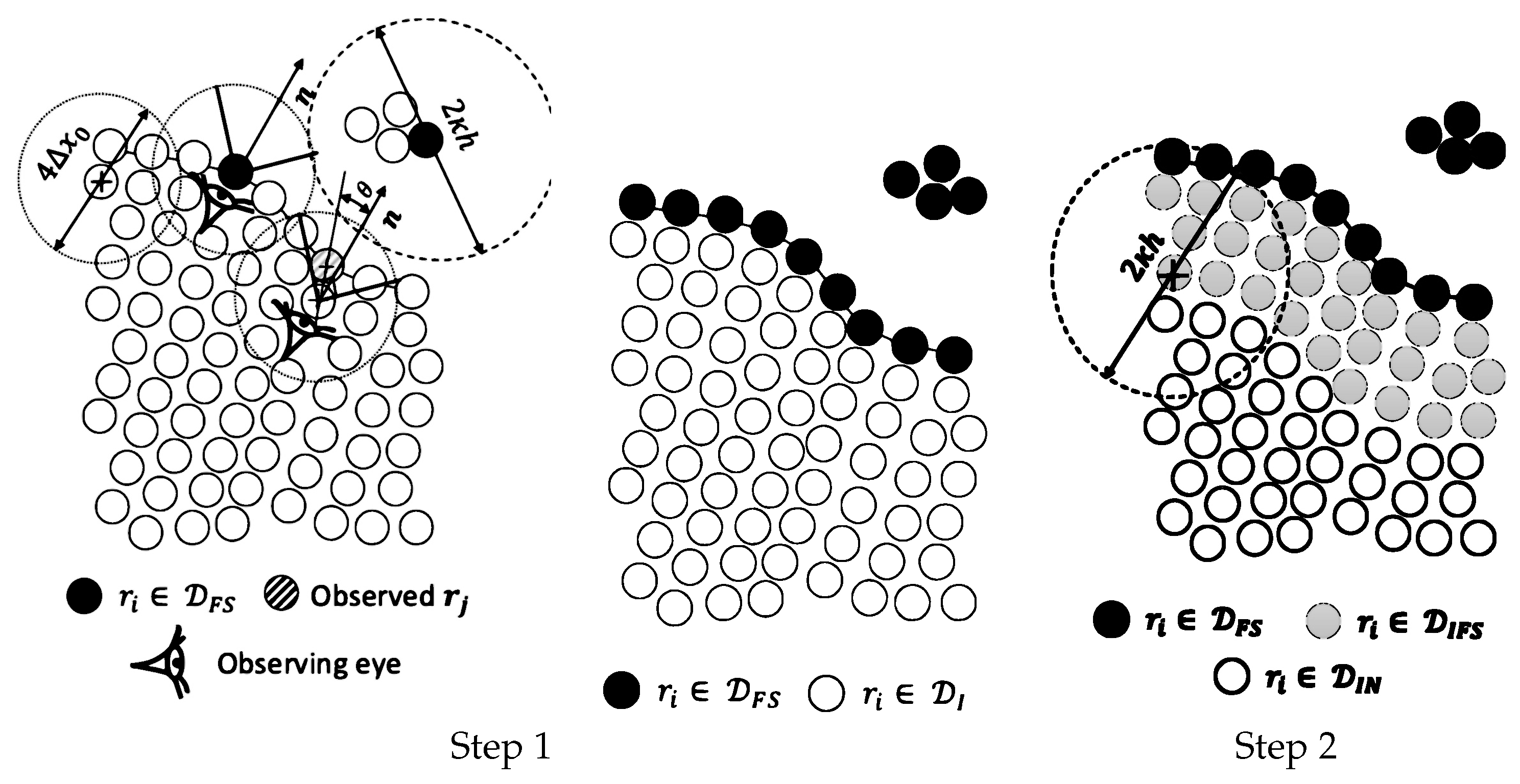
In this study, we employ a simple geometrical technique for detecting the free surface particles comparable to the methods proposed in [45,46]. This technique uses the concept of human eye vision (see Figure 1 where the human eye is presented by particle i). The vision distance, 2 Δ x 0 , and the angle of vision, θ , define the vision field corresponding to particle i. In the first step of the detection, if the particle i observes any particle within its vision field, the algorithm considers particle i as an inner particle, r i D I . Otherwise, as the vision area is empty, particle i is a free surface particle, r i D F S (see step 1 of Figure 2). Moreover, to distinguish the splashed particles, if the number of neighboring particles of particle i, N i , is less than or equal to N m i n ( N m i n = 8 in 2D or 26 in 3D), the algorithm treats particle i as a free surface particle. To specify the normal vector, n i , we utilize the re-normalization matrix, L i , as follows:
n i = L i j i W i j V j | L i j i W i j V j |
in which the symbol | . | denotes the magnitude of vector { . } . We summarize the first step of the free surface detection algorithm as follows:
arccos r ij · n i | r ij | θ 2 a n d r ij 2 Δ x 0 o r N i N m i n
where r ij = r j r i and particle i satisfying this condition is considered as aneps inner particle ( r i D I ), otherwise, it belongs to the free surface particles ( r i D F S )).
In the second step, we identify the particles which have at least a free surface particle ( r j D F S ) within their neighbor list (as the kernel support is expected to be truncated). To do so, the fluid particle i situated near the free surface region is considered as the inner free surface particles (i.e., r i j k h as r j D F S then r i D I F S ). In other words, all particles that do not belong to the free surface and have at least one free surface particle as a neighbor are considered as inner free surface particles ( r i D I F S the particle colored with gray color in Figure 2). The rest of the particles are the inner particles with the complete kernel support ( r i D I N ) (see step 2 of Figure 2).
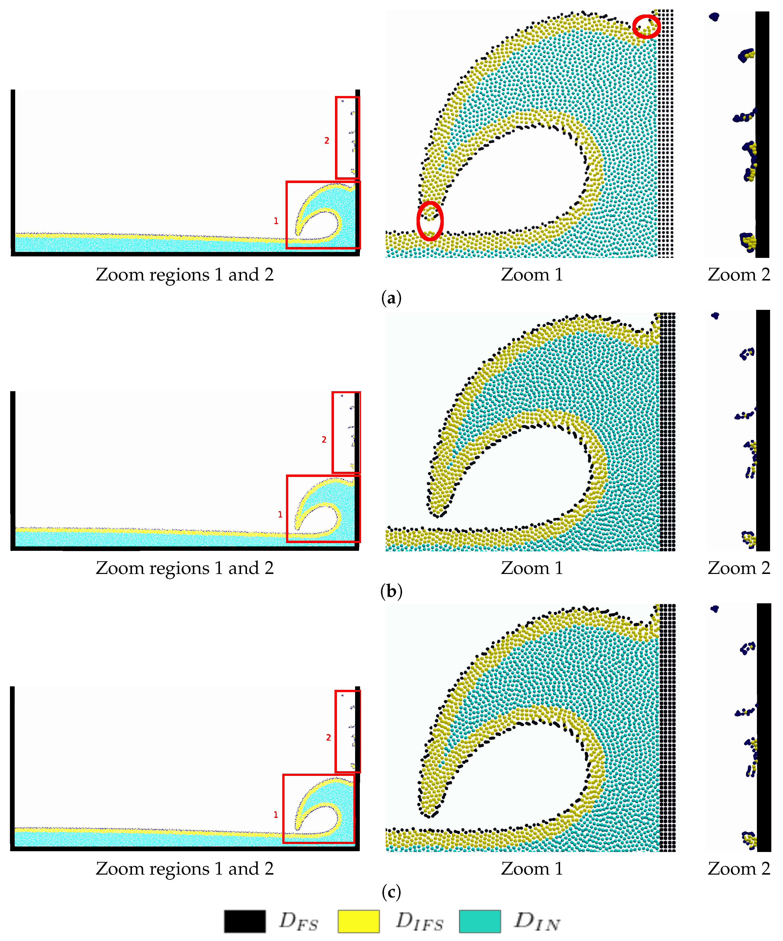
We compared our eye vision technique with the umbrella-shape area implemented in the free surface detection algorithm proposed by [45,47] (Figure 3). compared with the original umbrella technique [45], our proposed algorithm presents more accurate detection of the free surface particles, particularly in regions where the wave-breaking event occurs (see the red circles in the zoom region 1 of Figure 3a). However, comparing to the method proposed by Jandaghian and Shakibaeinia [47], a very similar results for the free surface particles are observed. This is due to the conservative searching region we consider for the vision field of the particles. It is worth to note that the proposed method is time-effective since less arithmetic operations are required (in comparison to [45,47] methods). Further, similar to the other searching areas and with some numerical simulation we found θ = π 2 to be a reasonable angle for the vision field in the benchmark test cases of this study.

3.2.2. Modified Particle Shifting Equation

To overcome the particles’ instability at the free surface region, we propose an enhanced version of the particle shifting equation. Herein, all the neighboring particles defined by the kernel function radius ( k h ) are considered for the SPH interpolation (unlike the IPST in [37]). A new parameter so-called ϕ is inserted into the equation to reduce the kernel truncation errors on the PS vectors close to the free surface. Further, a simple criterion based on the estimation of particle concentration C i is defined to limit the accumulation of errors in time caused by the continuous application of the PS. The new formulation is expressed as follows:
δ r i = ϕ CFL · Ma · 2 · h 2 · j ξ + χ i j i W i j V j
where χ i j denotes the artificial pressure-like function and is represented as follows [30]:
χ i j = R W i j W Δ x 0 n
in which R and n are constants set to 0.2 and 4, respectively [34,35,37]. CFL and Ma denote the Courant– Friedrichs–Lewy and Mach numbers, respectively and Δ x 0 is the initial inter-particle distance. We insert the parameter ξ into the PS equation given as:
ξ = 0 r i D F S r i D I F S 1 r i D I N
similar to the work of [37]. Particularly to modify the magnitude of the PS vector in the free surface region and specify the regions where the shifting is applied, we define ϕ by:
ϕ = 0 r i D F S r ij min . n j min k h r i D I F S 1 r i D I N 0 C i < 0.98 r i D I N
in which r ij min = r j min r i as the particle position r j min is the nearest free surface particle to particle i. C i denotes the concentration of particles located at r i and is given as:
C i = j W i j V j
As the PS manipulates the potential energy of the system in the long-term simulations (by decreasing the particle concentration and expanding the fluid domain, i.e., C i < 1 ) it is necessary to overcome this problem for modeling the free surface flows with several breaking events (e.g., Sun et al. [36] included additional diffusive terms into the continuity and momentum equations to compensate the effects of the nonphysical advection of the flow and material properties). Here, to deal with this issue caused by the PS technique, we deactivate the shifting of the inner particles ( r i D I N ) in the regions where their particle concentration reduces to less than 0.98 (i.e., if C i < 0.98 then ϕ = 0 ). The threshold value of 0.98 is chosen according to the nummerical expriments.Thanks to this simple criterion within the PS formulation, the long-term simulations of the violent free surface flows become possible (without implementing the additional diffusive terms into the governing equations). Furthermore, since the projected quantity, r ij min . n j min k h , changes smoothly from 0 to 1 (on the normal direction started from the free surface to the inner region) ϕ dynamically adjusts the magnitude of the PS vectors at the vicinity of the free surface (Figure 4—left). It should be noted that this term also deactivates the shifting of particles that the free surface detection algorithm may miss to consider as the free surface particle (poor estimation of free surface particles) (see Figure 4—right).
Note that the particle groups D I F S , D F S and D I N are already defined through the Figure 3.

4. Validation

Four challenging benchmarks are simulated to show the ability of the present work to achieve accurate and stable simulations. The first benchmark consists in the simulation of oscillating droplet under a central conservative force field, whereas for the second benchmark is devoted to simulate the evolution of initially-square fluid patch. These two problems cannot be simulated neither with the classical δ SPH method nor with the standard SPH one [59], due to the presence of strong tensile instability that may introduce un-physical fragmentation to the fluid domain. Via these two first benchmarks, we show the superiority of our enhanced PS formulation comparing to the one developed by Wang et al. [37] in terms of accuracy, stability, and energy conservation even when the free surface particles are poorly detected. The third and fourth benchmarks are devoted to simulate violent free surface flow, where dam-break and sloshing tank are chosen. It is known that the classical δ + -SPH scheme presents a weakness for the simulation of this kind of fluid flows. This is caused by the continuous introduction of the Particle shifting to the Lagrangian fluid displacement that subsequently promotes the accumulation of errors in time. The accumulation of theses errors can generate an un-physical expansion of the fluid domain when breaking events of violent free surface are presented [36]. Via these last benchmarks, we will demonstrate that our proposed technique can limit with such kind of problems.

4.1. Oscillating Droplet Uunder a Central Conservative Force Field

In this problem, a two dimensional water drop that initially has a circular shape with radius of R = 0.5 m evolving under central force field is simulated. The central force field f per unit mass is acting on the fluid as a body force and it is expressed in the Equation (16). Furthermore, the fluid drop is initially subjected to the velocity field expressed via the Equation (17) and has as density ρ = 1000 kg / m 3 . This test case is initially proposed by Monaghan and Rafiee [60], and after has been known as a good benchmark for SPH schemes validation [36,37,58,59,61] since its theoretical solution is available. The circular droplet oscillates and evolves like an ellipse in time, we define a and b as the semi-major and semi-minor axis of the evolving ellipse. The schematic of this problem is illustrated in Figure 5.
f = Ω 2 x , Ω 2 y T
u ( x , y , 0 ) = σ 0 x , σ 0 y T
where Ω denotes the dimensional parameter and it is taken as 1.5 s 1 . The global dynamics of the osculating drop depends on the ratio σ ( 0 ) / Ω , Here it is equal to 1. Thus, the initial value of the transient velocity parameter σ ( t ) is then σ 0 = σ ( 0 ) = 1.5 s 1 .
The theoretical solution for the oscillating fluid droplet in the case of single phase can be obtained by the simplification of the multi-phase formulation developed by Monaghan and Rafiee [60] and can be read as
d σ ( t ) d t = σ ( t ) 2 + Ω 2 b ( t ) 2 a ( t ) 2 b ( t ) 2 + a ( t ) 2 d a ( t ) d t = σ ( t ) a ( t ) a ( t ) b ( t ) = R 2 σ ( 0 ) = σ 0 = 1.5 a ( 0 ) = b ( 0 ) = R
The theoretical solution is obtained by solving the system of Equation (18) using Rung–Kutta 4th ordern algorithm [62]. After solving the system of Equation (18), the theoretical kinetic, Potential and total energies can be calculated, respectively as follows [60]:
E k ( t ) = π 8 σ ( t ) 2 a ( t ) b ( t ) a ( t ) 2 + b ( t ) 2 ρ 0
E p ( t ) = π 8 Ω 2 a ( t ) b ( t ) a ( t ) 2 + b ( t ) 2 ρ 0
E T = E k + E p
The presented SPH model, has been applied on this benchmark under two different particle resolutions that correspond to the initial inter-particle distances of d x = R 50 and d x = R 100 . The artificial speed of sound c 0 is set to 15 σ 0 R to match with the weakly-compressible hypothesis.
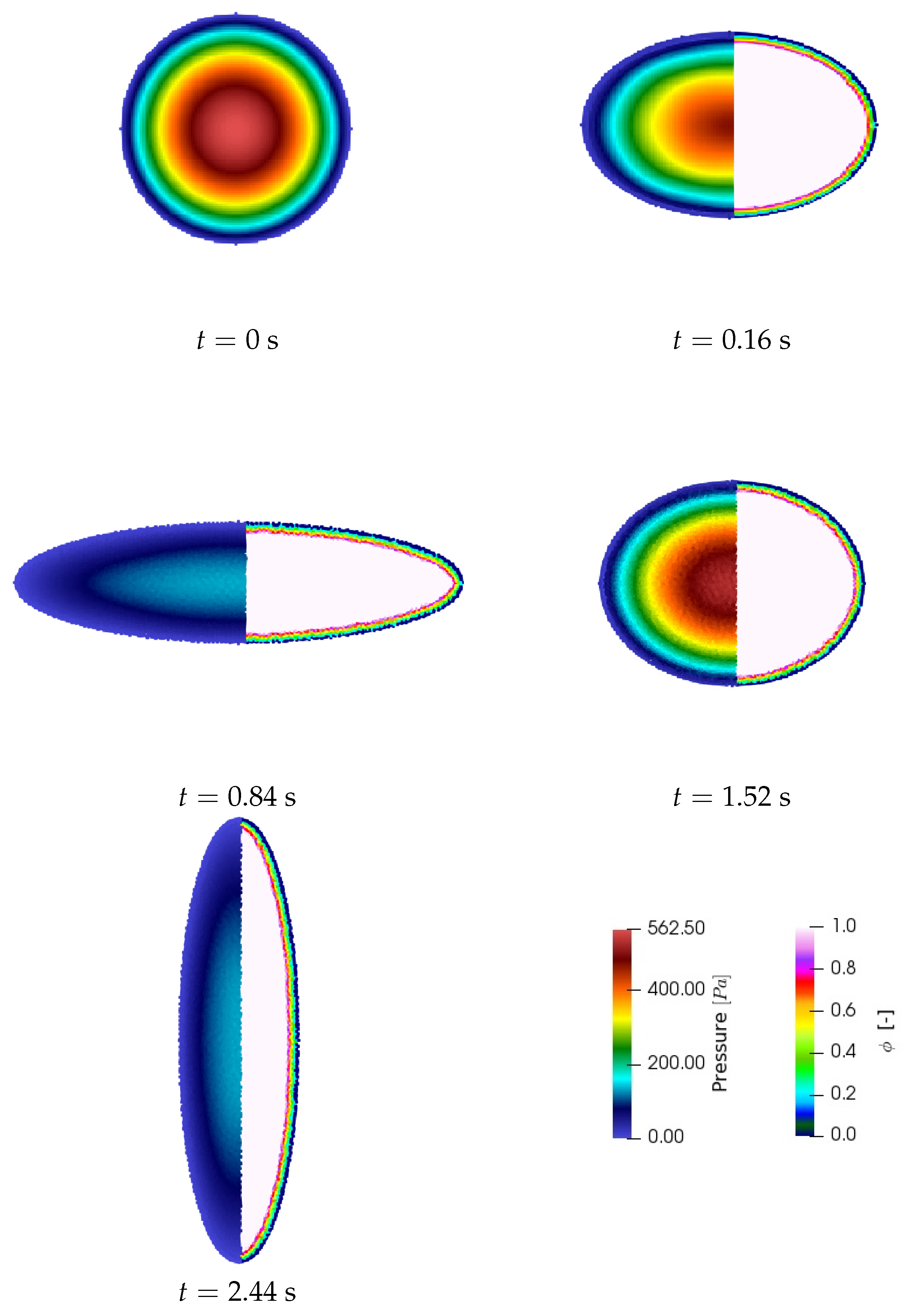
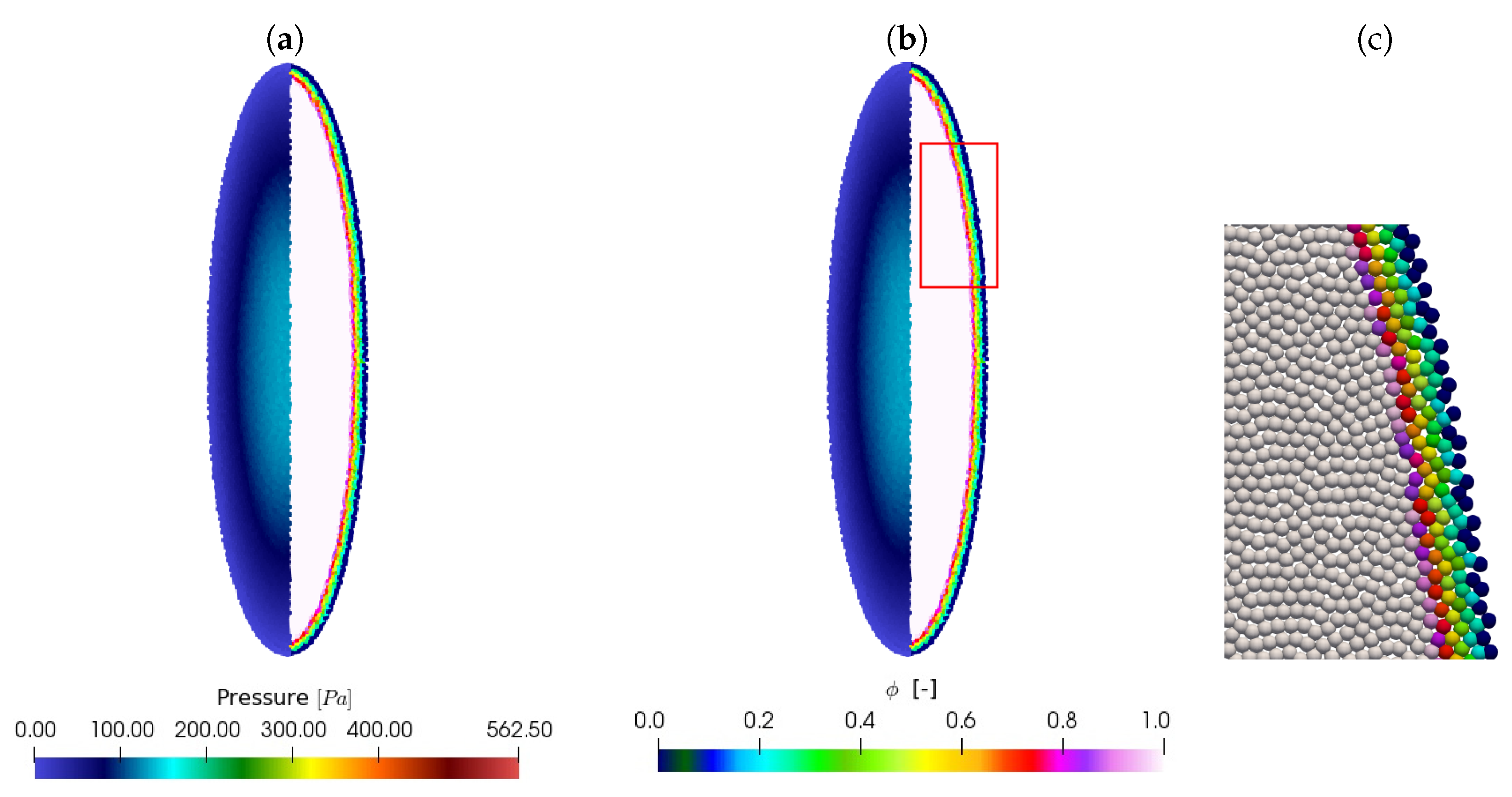
Figure 6 presents the shape evolution of the oscillating droplet for five time steps t = {0, 0.16, 0.84, 1.52, 2.44} s under the resolution ( d x = R 100 ). The fluid particles are colored with pressure filed on the left half of the droplet and with ϕ parameter field on the right half. In Figure 7, the fluid drop under the resolutions d x = R 100 and d x = R 50 at the time t = 2.44 s are represented respectively via the snapshots (a) and (b) of Figure 7. As in the previous Figure 6, the fluid particles are colored with pressure and ϕ - parameter on the left and the right half of the droplet, respectively. Through the zoom region of Figure 7b presented in Figure 7d, we show that the parameter ϕ varies from 0 to 1 normally from the free surface particle to the inner particles region, which grantees subsequently the progressive application of particle shifting near free surface region as we expect.
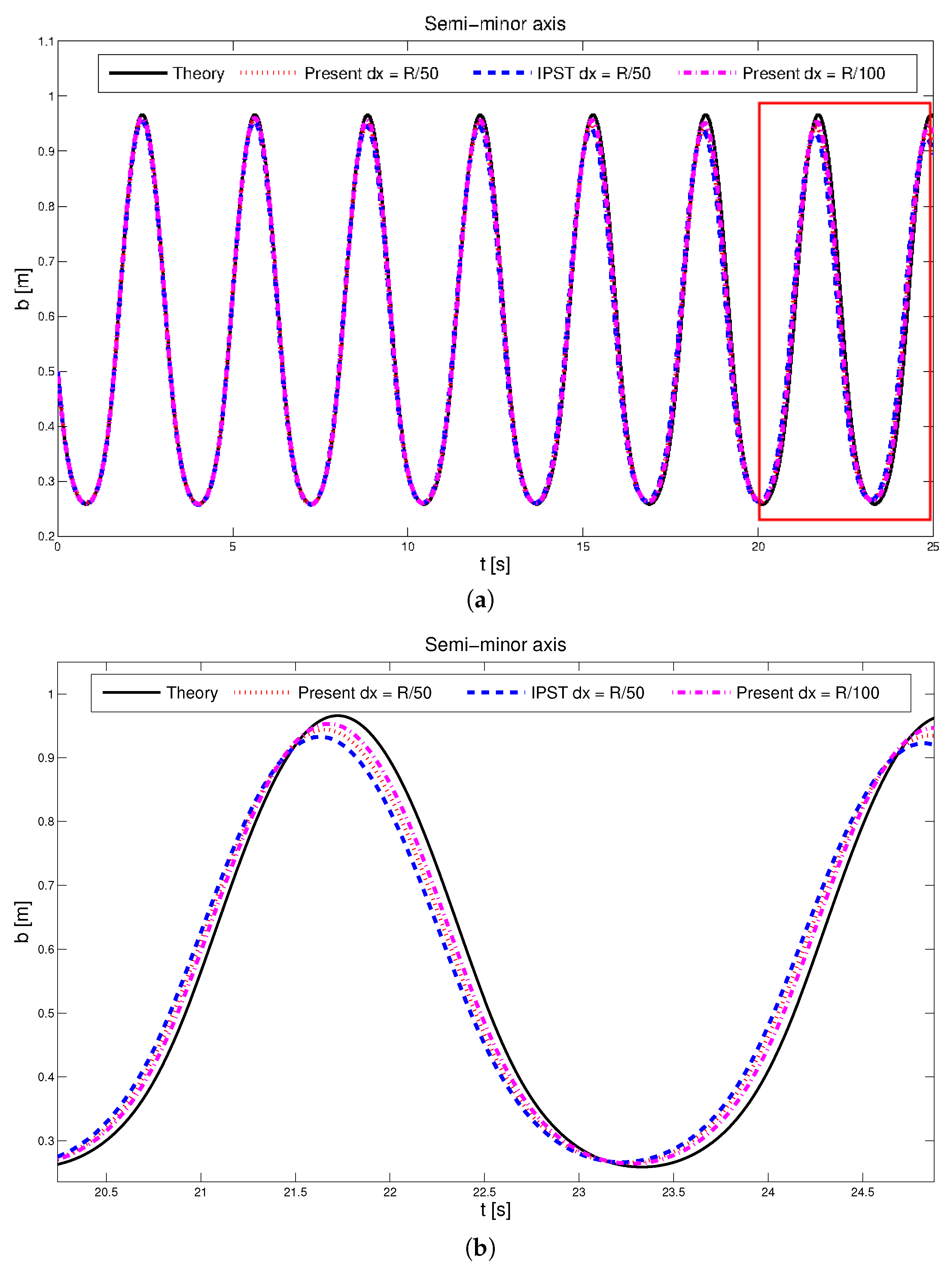
Figure 8 and Figure 9 show the time evolution of semi-major ( a ( t ) ) and semi-minor ( b ( ( t ) ) axis of the fluid droplet, respectively. A quantitative comparison between the theoretical results [60], the Improved particle shifting technology IPST proposed by Wang et al. [37] and the present work is also presented via these figures. It is shown that the present formulation of particle shifting gives more accurate results than the IPST formulation for both semi-major and semi minor axis under the resolution d x = R 100 . It is also shown that when we increase the particle resolution, the results tend to more converge to the theoretical results.
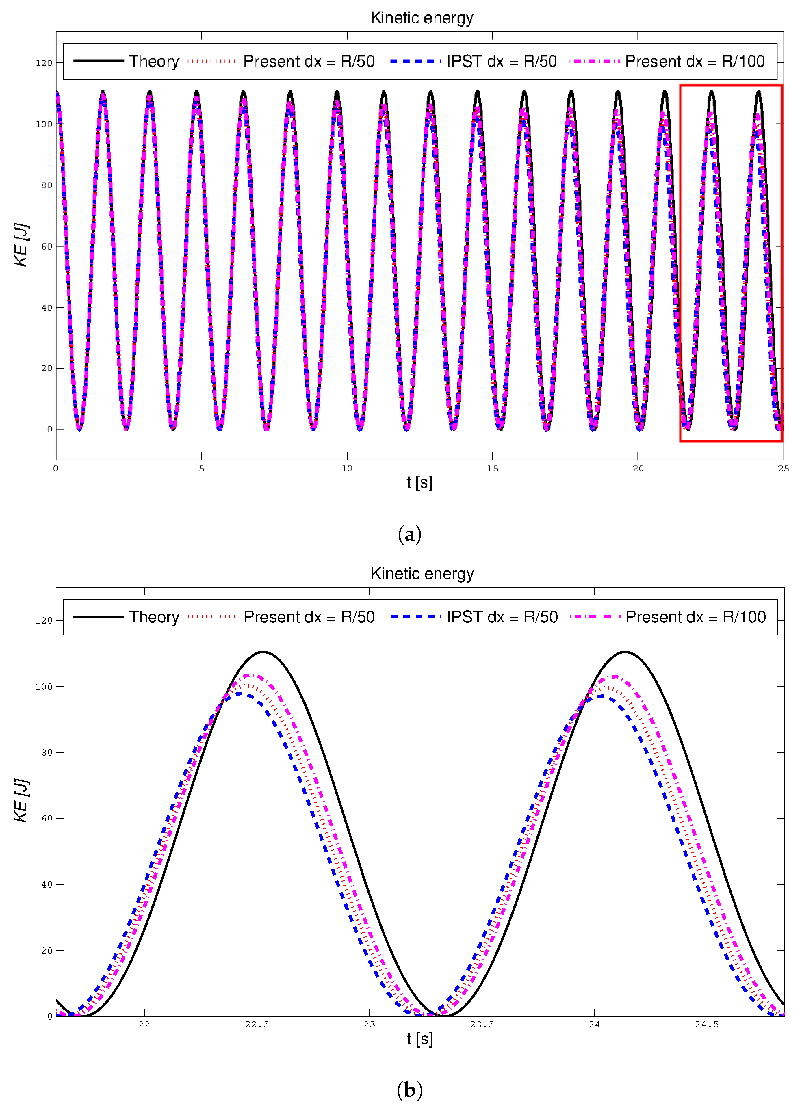
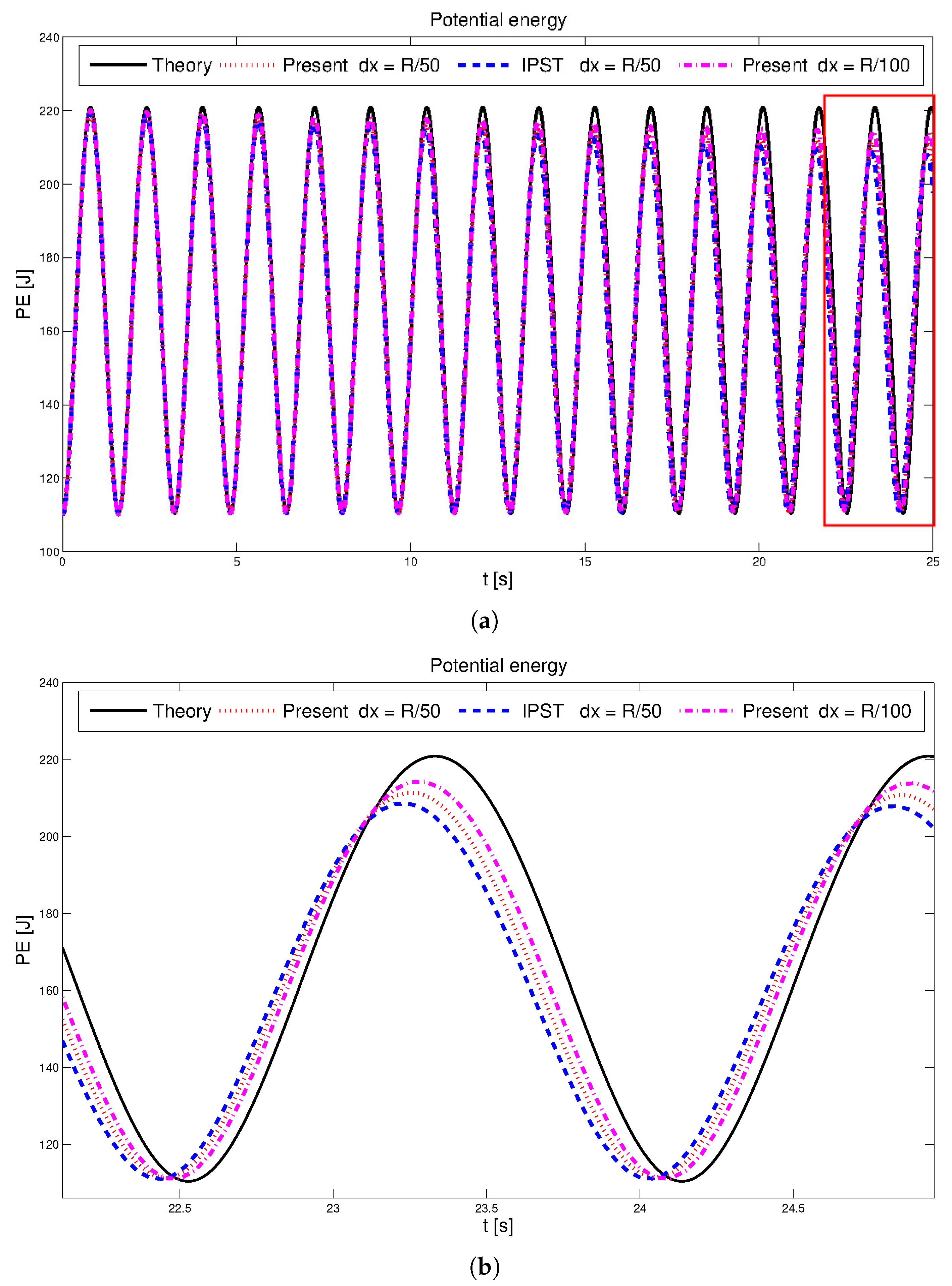
The time evolution of kinetic and potential energies of the osculating droplet are presented in the Figure 10 and Figure 11, respectively. Comparing to the theoretical results [60], we can remark that the present formulation provides better results in terms of kinetic and potential energies than the results obtained by using IPST [37]. With increasing of particle resolution ( d x = R 100 ), the evolution of kinetic and potential energies converges greatly to the theoretical solutions.
In the Figure 12, the time evolution of total energy is plotted. It is shown that the present particle shifting formulation is more conservative than the IPST formulation proposed by Wang et al. [37]. It is also shown that the present particle shifting formulation dissipates less energy when a higher resolution of particles is used.
It should be noted that in this simulation, the particle shifting was not limited over the time since the defined criterion always remains satisfied in the inner particle region ( C i > 0.98 ).
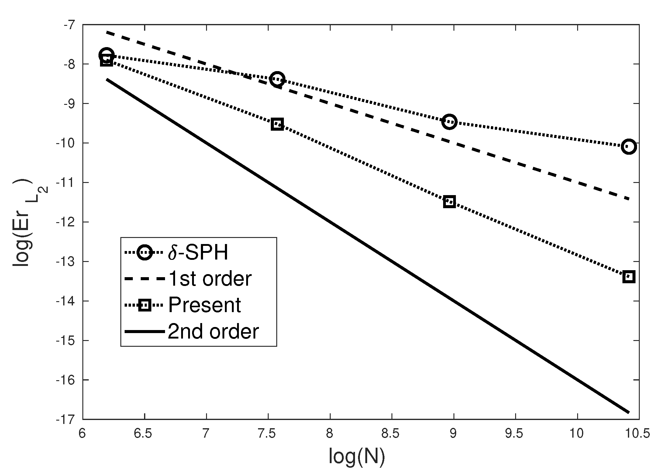
To quantify the error resulting from our present model and δ -SPH scheme [23] compared to analytical solution given by Monaghan and Rafiee [60], convergence studies were performed at the time t = 2.44 [ s ] under four particle resolutions including d x = R 12.5 , d x = R 25 , d x = R 50 and d x = R 100 that correspond to different particle numbers of N = 489 , 1945, 7821 and 31,377, respectively. The L 2 error ( E r L 2 ) was calculated at all particle positions based on the values of the horizontal velocity field obtained by our SPH model, δ -SPH and the analytical solution, Its formulation is given as in [63]:
E r L 2 = 1 N i = 1 N ( u i S P H u i A n a l y t i c a l ) 2
Here u i represents the values of the horizontal velocity of the particle i, Whereas for the subscript S P H indicates our present SPH model or the δ -SPH model and A n a l y t i c a l is the analytical solution. The results of the convergence study are shown in Figure 13, where it appears that the order of convergence of our present SPH model is comprise between 1 and 2, whereas for δ -SPH the presents a convergence order less than one.

4.2. Evolution of an Initially-Square Fluid Patch

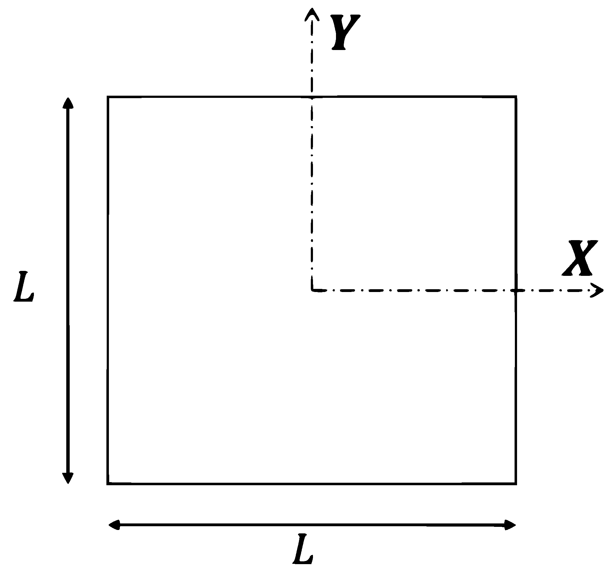
This test case presents an evolution of an inviscid fluid patch that initially has a shape of a square with side length L = 1 m (see Figure 14). This test is originally proposed by Colagrossi [64], and after it is used as numerical benchmark for the stability and accuracy assessment of particle methods [31,61,65,66]. The fluid square is initially subjected to a velocity field defined in the Equation (23) and pressure field obtained by solving the related Poisson equation (for more details, see [64]). Under these conditions, the fluid patch starts to rotate, and its middle part shrinks to the center, whereas for its corners extend to form gradually four fluid jets generated by the centrifugal force.
u ( x , y , 0 ) = ω y , ω x T
where ω = 1 rad / s denotes the constant angular velocity of the fluid path. The density of the fluid is taken equal to ρ = 1000 kg / m 3 .
For the numerical simulation, an initial regular particle distribution as Cartesian lattice is considered under two spacial resolutions of d x = L / 100 and d x = L / 200 (10,201 and 40,401 particles, respectively). The numerical speed of sound is taken equal to c 0 = 5 2 ω L .
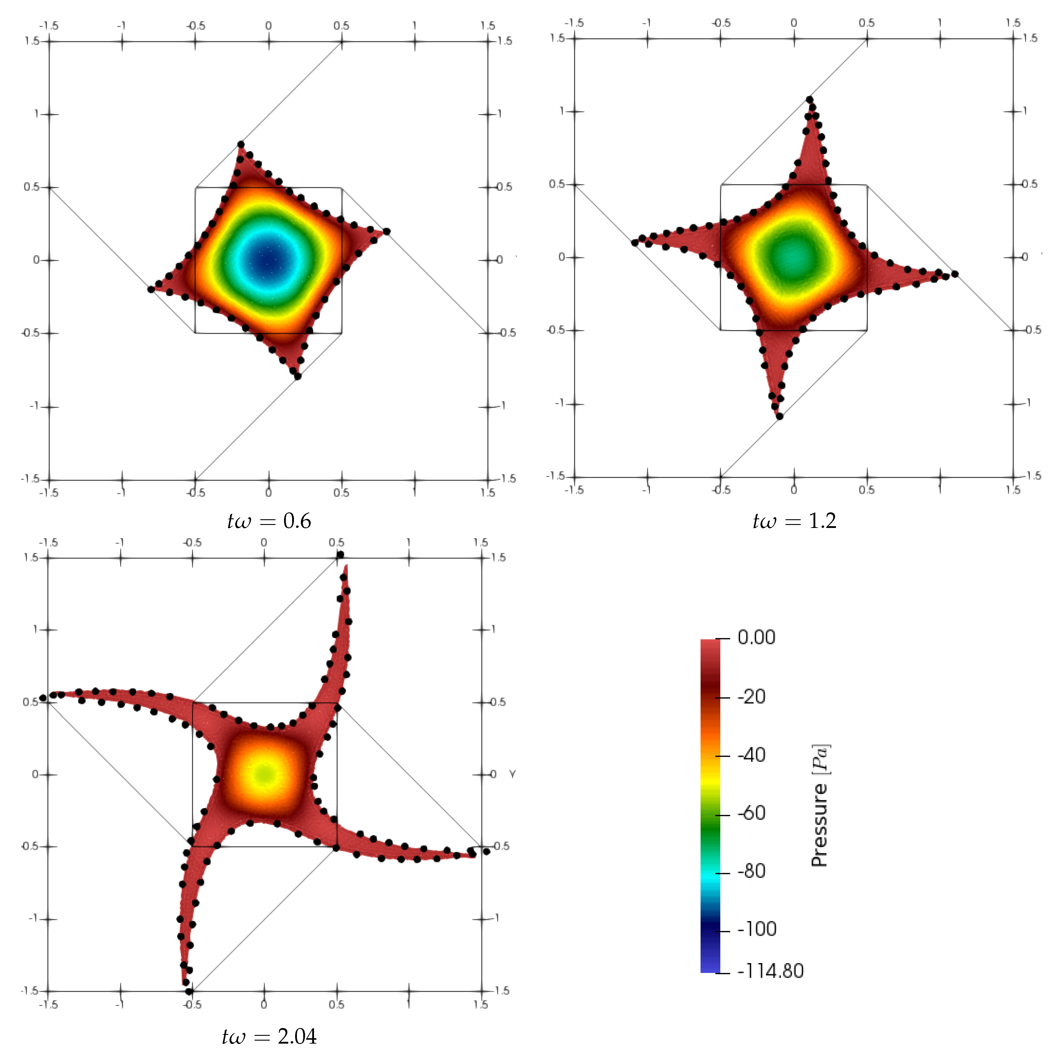
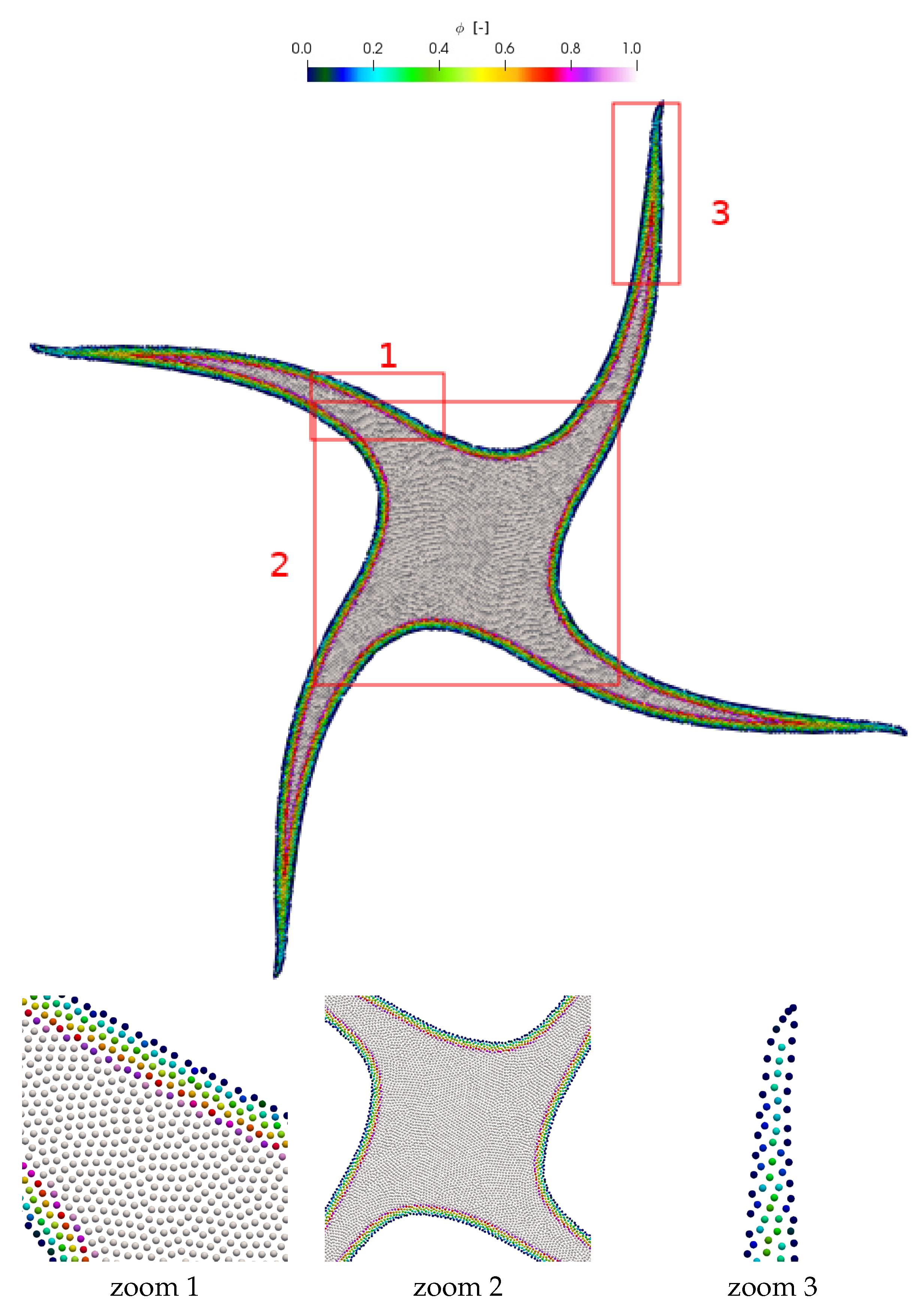
The evolution of the fluid path at three different dimensionless times t ω = { 0.6 , 1.2 , 2.04 } is plotted in Figure 15 under the particle resolution of d x = L / 100 . The fluid particles are colored with pressure field. The black nodes in the Figure 15 present the free surface obtained by using the Lagrangian finite difference method (FDM) [61]. A good agreement between FDM and present results in terms of free surface interfaces is observed.
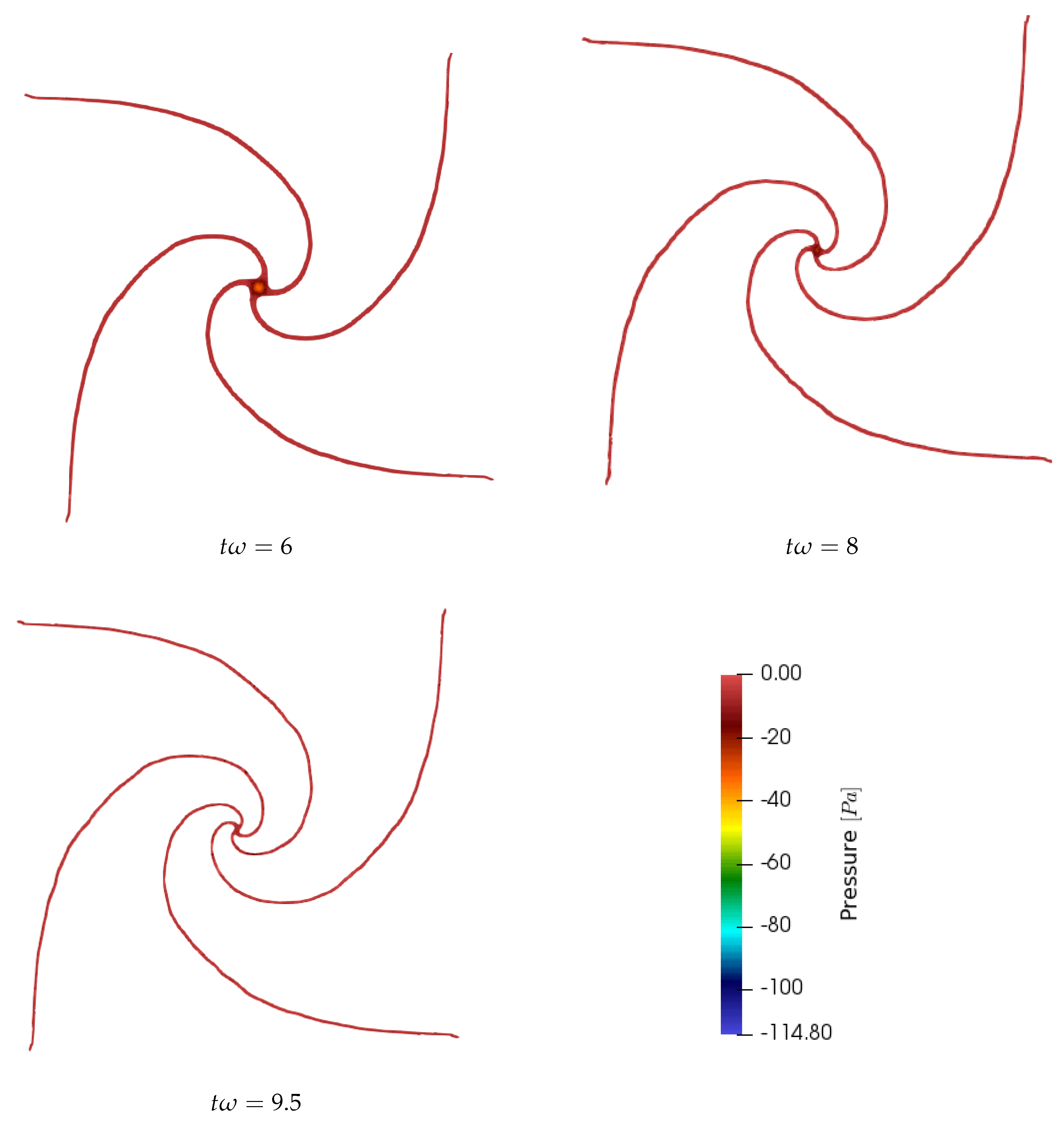
For a more advanced time, we present in the Figure 16 the evolution of the fluid shape at t ω = { 6.0 , 8.0 , 9.5 } under the particle resolution of d x = L / 100 . The four corners of fluid evolve in time and become thin and thin until reaching a fragmentation (abrupt disconnection of particles in the finest regions) caused by the lack of particular resolution. For the present resolution ( d x = L / 100 ), the fluid particles remain connected until time t ω = 9.5 , wheres for the resolution ( d x = L / 200 ), it can even exceed t ω = 12 .
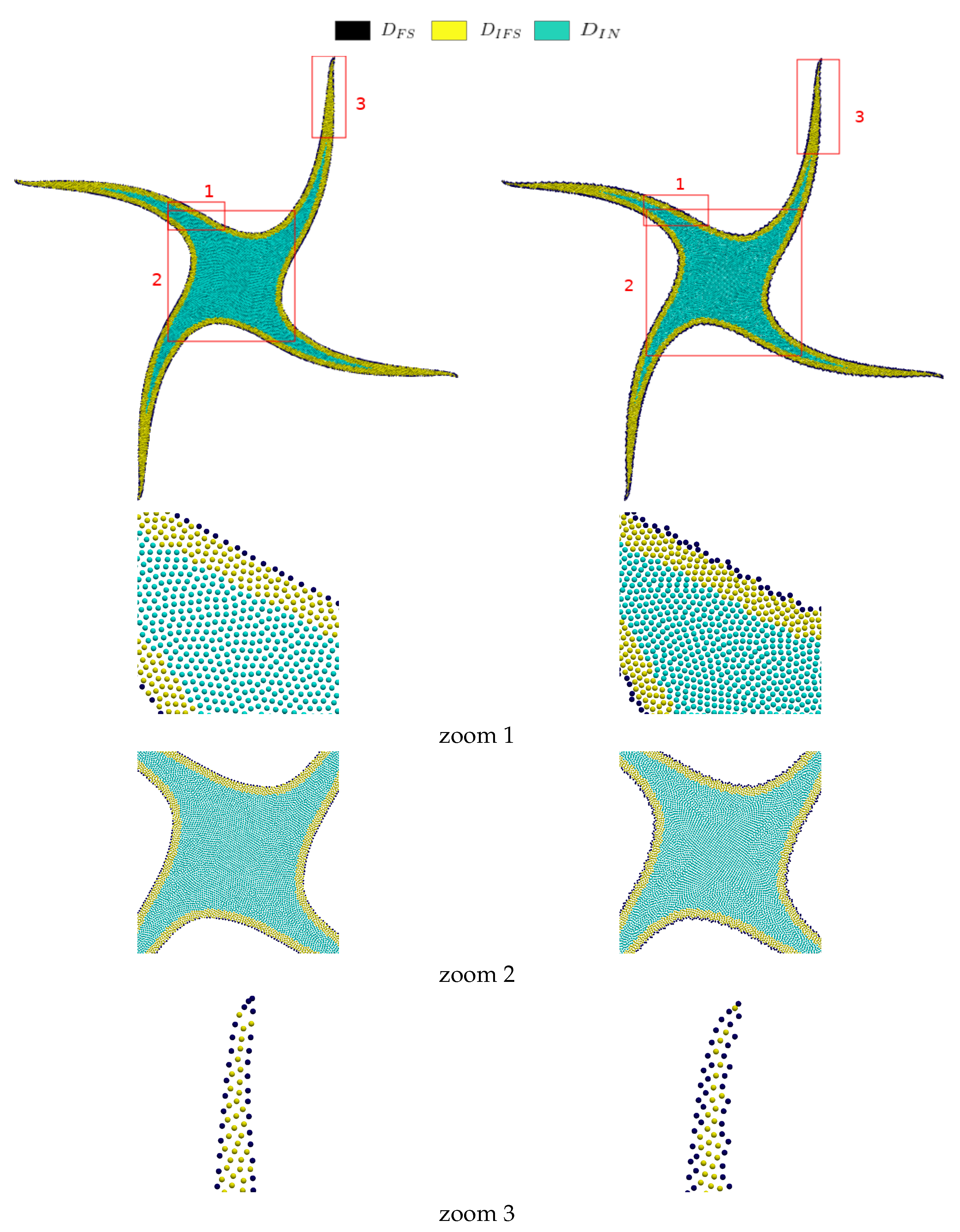
At time t ω = 2.2 the distribution of fluid particles obtained by using the present particle shifting model (the left column) and IPST model (the right column) [37] under the particle resolution of d x = L / 100 is depicted in the Figure 17.
To show the efficiency of our particle shifting model, we have deliberately used a value of θ = 0.95 π for the free surface detection algorithm in order to generate a poor detection of free surface particles, while θ is set to π 2 in the IPST model of [37] to have a good free surface particle detection. The Figure 17 shows the different regions of particles, where the free surface particles are colored with black color ( D F S ), the inner particles in the vicinity of the free surface ( D I F S ) are colored with yellow color, and interior particles ( D I N ) are colored with green color. Using our approach, it is clearly observed that in the fluid interface, there is some free surface particles that are not detected, and are considered as inner particles in the vicinity of the free surface ( D I F S ), since they are near to other detected free surface particles. From the right column of Figure 17 it is clear that a good detection of free surface particle is obtained. However, we observe that the free interface presents a low smoothness compared to our particle shifting approach.
Through the Figure 18, we show the ϕ parameter field can play the role of a corrective parameter where the poor detection of the free surface particles is appeared. The parameter ϕ takes values of zeros (or very close to zero) in non-detected free surface particles which subsequently exclude them from being shifted as expected and can be demonstrated by the Equation (11).
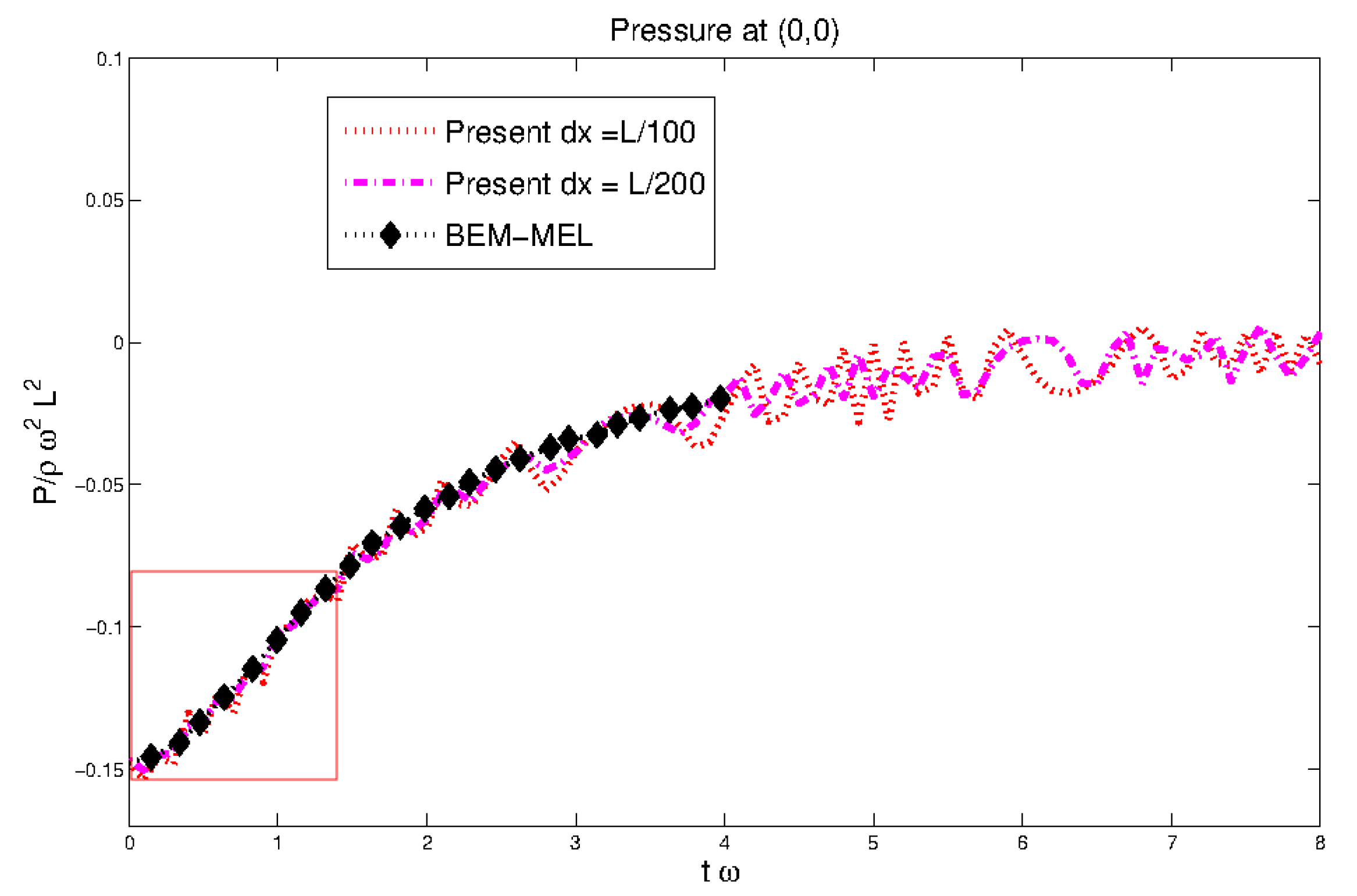
Figure 19 plots the time evolution of the pressure at the center of the fluid path for the particle resolution of d x = L 100 and d x = L 200 . We compare our results with the numerical results obtained by mixed Euler–Lagrangian-boundary element method (MEL-BEM) solver [61]. A good agreement in the overall behavior of the pressures is noted with the presence of oscillations due to the weakly-compressible fluid hypothesis. From the enlarged view (second row of Figure 19), it is shown that with the increase of the particle resolution, the pressure curve match more with the one of (MEL-BEM) solver [61] and presents less oscillations.
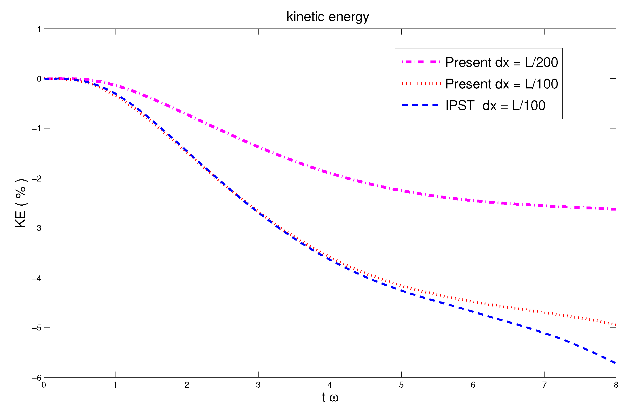
Figure 20 compares the dissipation of the kinetic energy (Equation (24)) for the present approach under two particle resolutions ( d x = L 100 and d x = L 200 ) and the so-called IPST proposed by Wang et al. [37] under the resolution of d x = L 100 . It is shown that with the increase of the particle resolution, the dissipation of total kinetic energy becomes less (at t ω = 8 , presents 2.7 % and 4.95 % of energy loss for the resolutions of d x = L 200 and d x = L 100 , respectively). It is also shown that the proposed particle shifting strategy has a better performance in terms of energy conservation comparing to IPST [37] at the same resolution d x = L 100 .
K E ( t ) = i u i ( t ) i u i ( 0 ) 1 × 100
As we have noted previously in Section 4.1, the defined criterion always remains satisfied in inner particle region part ( C i > 0.98 ), and thus the particle shifting is applied contentiously to the Lagrangian displacement during all the simulation time.

4.3. Dam Break Problem

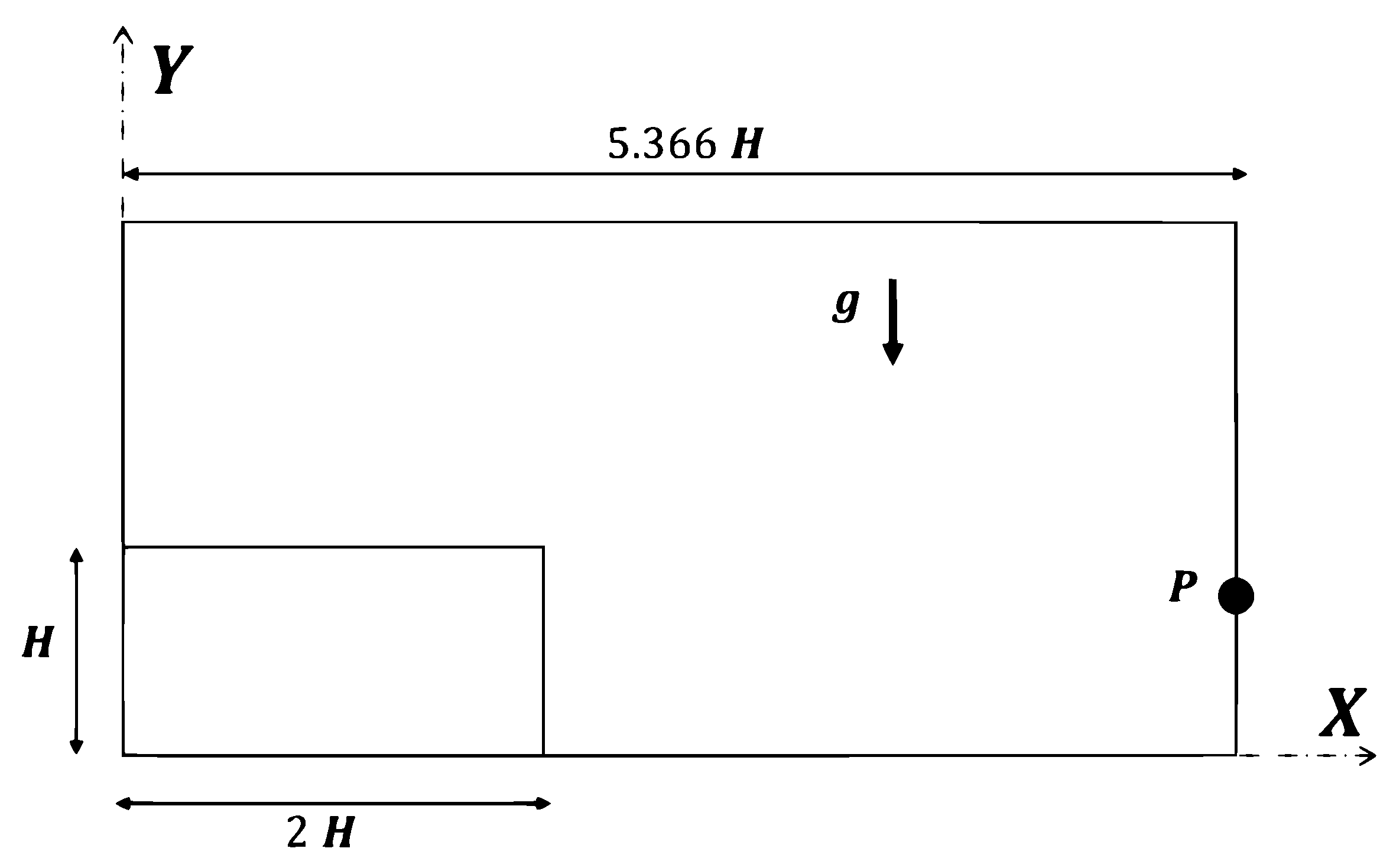
For this validation test case, we consider a two-dimensional dam break problem. This test has been experimentally investigated by several authors such as Martin et al. [67], Zhou et al. [68] and Buchner [69]. Since the generated flow is of complex with large deformation natures, it is becoming one of the most used benchmarks to validate SPH and other particle-based methods [23,47,57,70,71,72,73]. The initial configuration of the problem is illustrated in Figure 21. A water column of height H and length of 2 H is located in a rectangular tank of length 5.366 H . Here, H is taken equal to 0.6 m as in the experimental test of Buchner [69]. The water flow is considered inviscid with a density of 1000 kg / m 3 . The water column flows under the effect of gravity acceleration g = 0 , 9.81 T . To record the pressure signal, a pressure probe P located at the downstream wall exactly at y / H = 0.19 from the bottom of the tank is used (see Figure 21). Note that the probe position is slightly different from the experiments, and shift produces a better agreement with the SPH method due to several uncertainties in the measurements [74].
A particle resolution of 12,800 particles that corresponds to d x = H / 80 was considered for the simulation using our present particle shifting approach and that proposed by Wang et al. [37]. The formulation of analytical solution of the Poisson equation on the water column (see [75]) is used to initialize the pressure field. The water column is considered at rest at the time t = 0 , and thus the initial velocity is taken equal to zero for all particles. The numerical speed of sound used for the simulation is taken as c 0 = 10 2 g H .
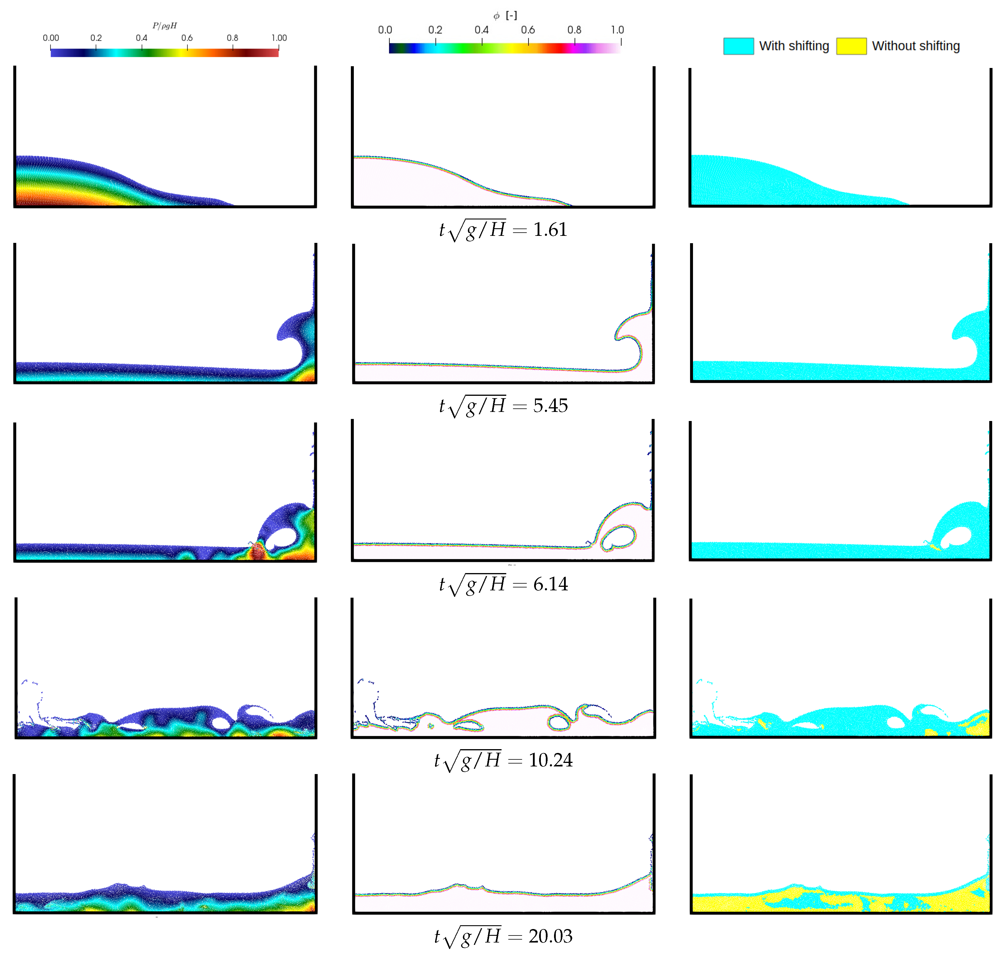
Several snapshots of the pressure field, ϕ parameter field and particle shifted regions at different time instances are shown in Figure 22. The obtained results present relatively smooth pressure field with a very low-frequency noise thanks to the application of particle shifting strategy. We can see via the second column of Figure 22 that the ϕ parameter field seems to well follow the free surface particles and it is also well defined through the vicinity region of free surface particles, which subsequently guarantees the correct application of the present particle shifting strategy. The last column shows with blue color the region when our particle shifting technique is considered, whereas for regions with yellow color, the shifting is excluded as in theses regions the errors caused by the continuous shifting are considered highly accumulated (extended fluid regions with C i < 0.98 ).
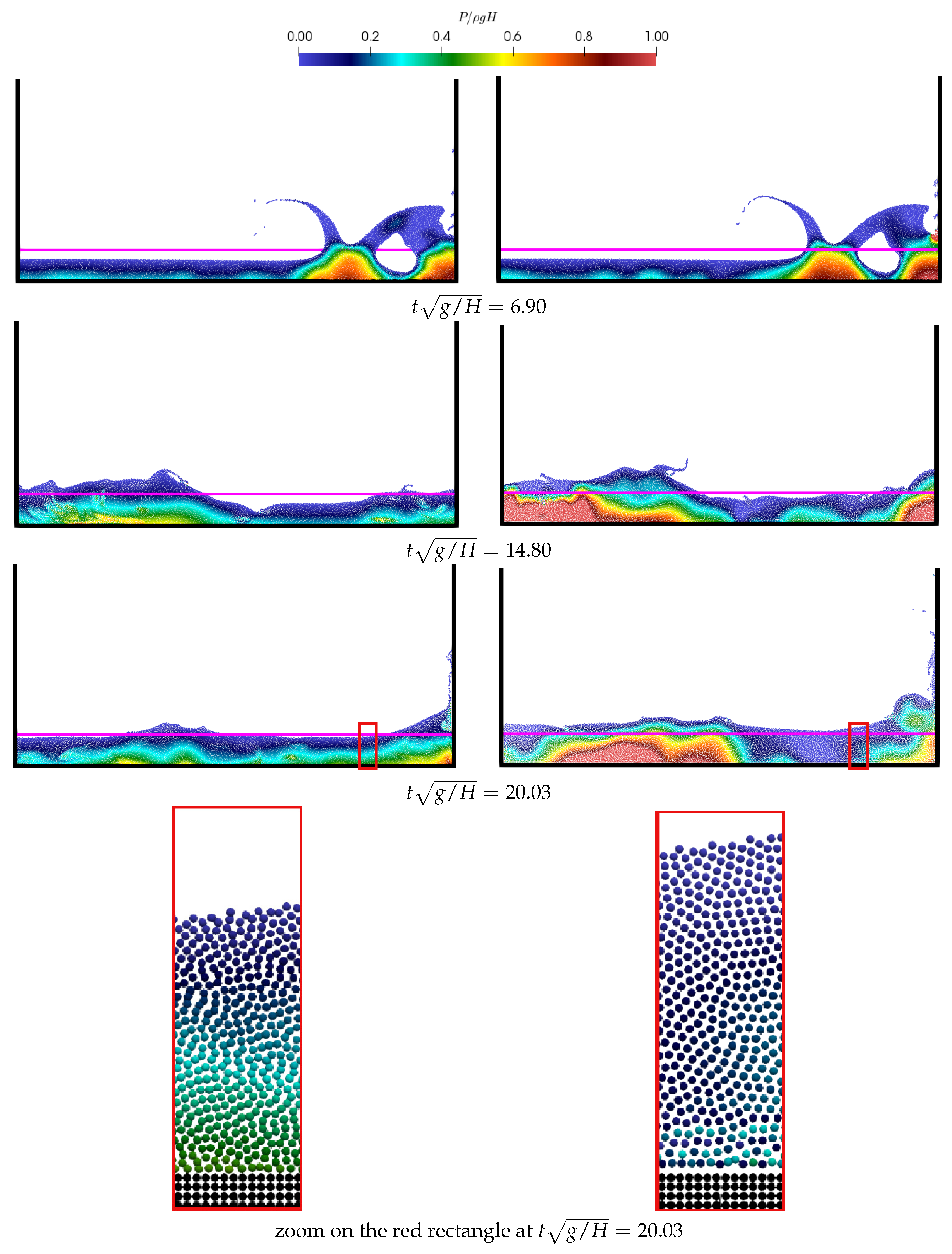
The Figure 23 depicts a comparison between the present particle shifting strategy, and IPST developed by Wang et al. [37] at three different times t g / H = { 6.00 , 14.80 , 20.03 } . A very similar results between the present and IPST approaches, are shown in the early stage of simulation when the inner fluid region remains unextended (here, the defined criterion is always satisfied: C i > 0.98 ). After, when the breaking event becomes more important ( t g / H > 7 ), the continuous process of shifting using IPST approaches will cause an accumulation of errors in time and can be manifested as un-physical expansion of the total fluid domain ( C i < 0.98 ). The right column shows the results obtained by IPST approach [37], we observe that total volume the free surface level at the later stage (advanced timing) is tending to be more and more higher than the expected one (magenta solid line found at the height of y 0.3748 H ), whereas for the left column where our approach is used, the free surface level tends to match with the expected theoretical level.
It should be noted that the expansion of the fluid volume is principally due to the continuous application of the particle shifting to the particle displacements, and not because of IPST technique developed by Wang et al. [37].
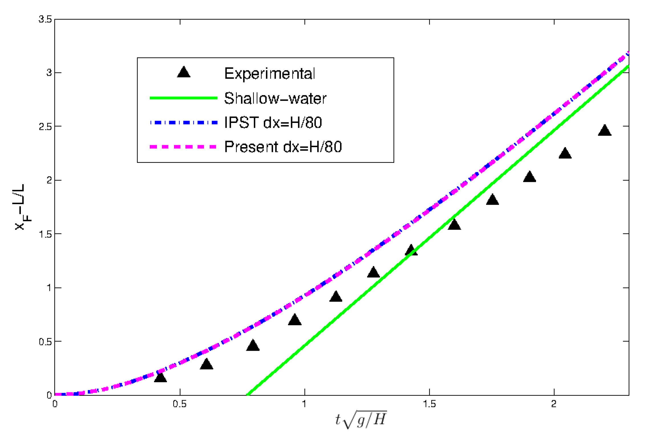
The dimensionless water wave front X f ( X f = x f 2 H H , with x f being the x coordinate of the water front) obtained by the present particle shifting strategy and IPST are compared with the analytical solution obtained from shallow water theory [76], and experimental data given by Buchner [69] in Figure 24. A perfect agreement is shown between both numerical approaches since at this stage the accumulated errors due to the use of particle shifting is not significant (non-expansion is observed during all the time presented in Figure 24, in other words, C i > 0.98 everywhere in the inner particles). As a quantitative comparison, the numerical results correspond relatively to the analytical solution from shallow water theory [76], and experimental data given by Buchner [69], however, it should be noted that a slower front wave is observed in experiments caused by several factors such as uncertainties of the measurements and wall roughness [77].
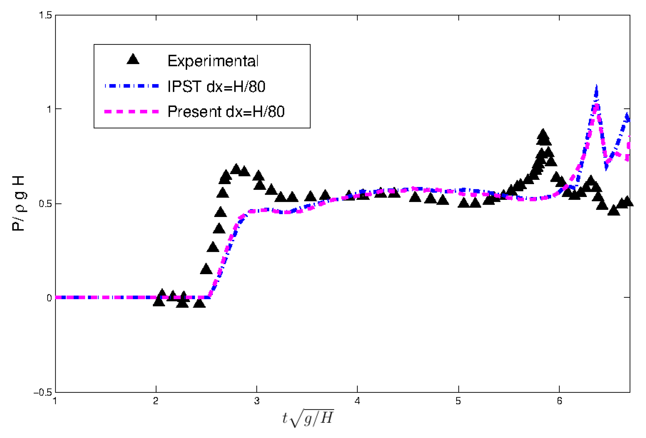
Figure 25 shows the time history of the recorded impact pressure signals on the right vertical wall at probe P. A very good compatibility is observed between the present particle shifting strategy and IPST developed by [37] since the measurement is done on the early stage of the simulation. Both numerical methods are with good agreement in the overall behavior with experimental data presented by Buchner [69]. The difference between numerical and experiments specially for peak pressures can be due to the influence of the air-cushioning cavity on the sensor measurement which is not taken into account in the numerical simulation (see [70]), and also the 3D effects.
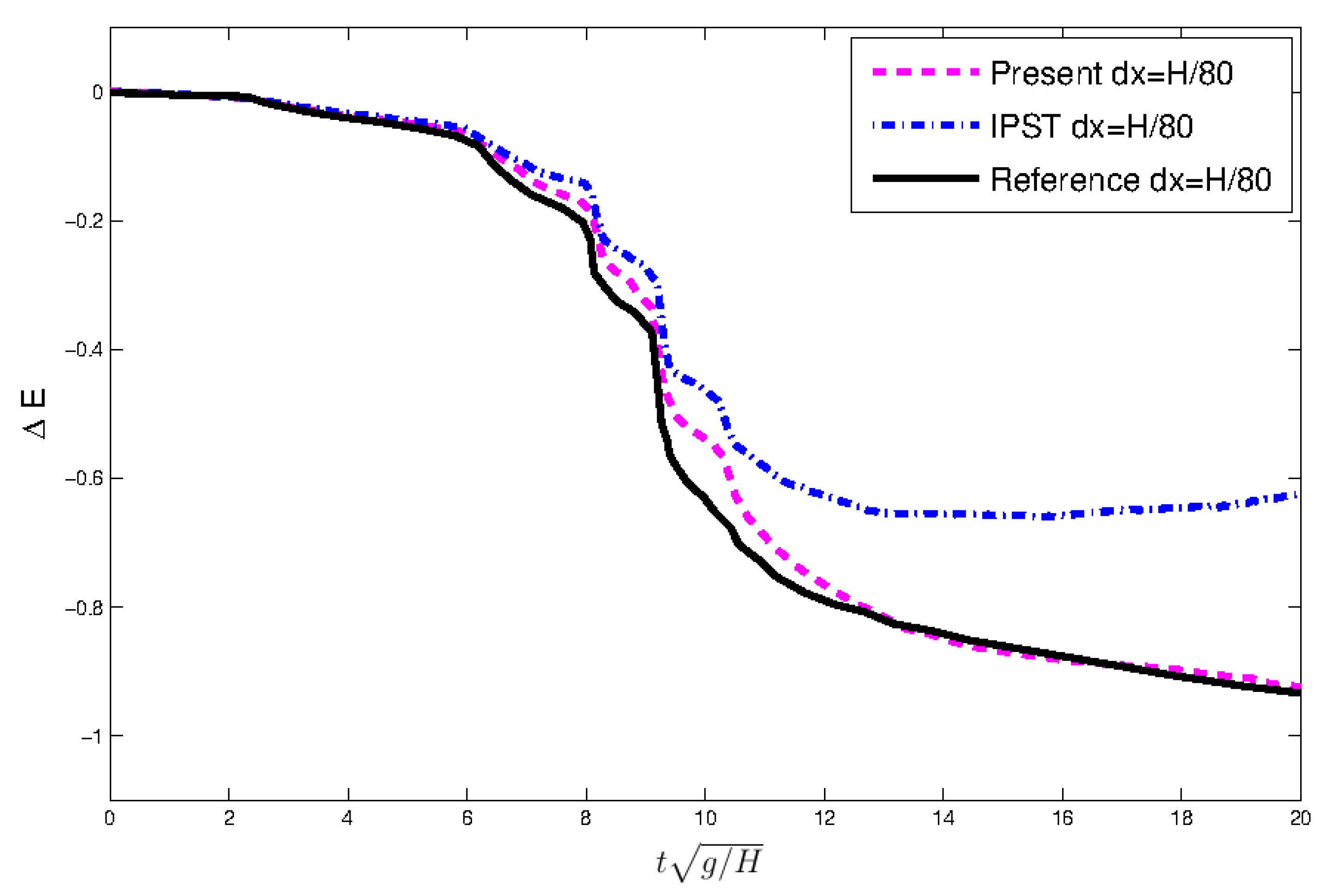
The time evolution of the numerical dissipation of mechanical energies Δ E obtained with the present particle shifting technique, IPST approach [37] and reference results of Marrone et al. [23]. ( δ S P H scheme) are plotted in Figure 26. The formulation proposed by Marrone et al. [23] is used to calculate Δ E , and it reads as
Δ E T = E k ( t ) + E p ( t ) E p 0 E p 0 E p
where E k ( t ) is the time evolution of kinetic energy, E p ( t ) the potential energy, E p 0 the initial potential energy and E p the potential energy when the flow reaches a hydrostatic steady state. A quantitative agreement is observed between the results obtained by the proposed particle shifting technique and the reference results of Marrone et al. [23]. Whereas for the results obtained by using IPST approach [37], a non-physical increase in mechanical energy is observed. This is caused by the increase in kinetic energy which is revealed by the non-physical expansion of the fluid particles (see the zoom regions in Figure 23 at t g / H = 20.03 ). This non-physical expansion of the total fluid domain is principally due to the breaking events that promote the accumulation of shifting errors to the Lagrangian displacement of the particles [36].
Through the Table 1, we compare the computational times obtained by using our present particle shifting formulation and IPST [37] for simulating 5 s of the physical time of the dam break case under 12,800 particles. It is found that our method takes a little longer than IPST [37], which is quite expected since in our method additional computational tasks are required as for calculating ϕ -parameter and expansion criterion are added. Both simulations are done in serial calculation on a machine equipped with a processor model: Intel(R) Core(TM) i7-6700HQ CPU @ 2.60 GHz and Random-access memory of 8 GB.

4.4. Sloshing in a Rectangular Tank

Through this test case, the motion of a fluid inside a partially filled tank that is subjected to periodic motion is numerically investigated. This flow is known as the fluid sloshing problem [78,79]. When the frequency of the tank motion is close to the natural frequency of the fluid due to gravitational wave, the resonance conditions prevail and may cause important loads impacts to the tank structures. Because this phenomenon is of complex and highly non-linear nature, the liquid sloshing flow has been used in several works to validate SPH models [77,80,81,82].
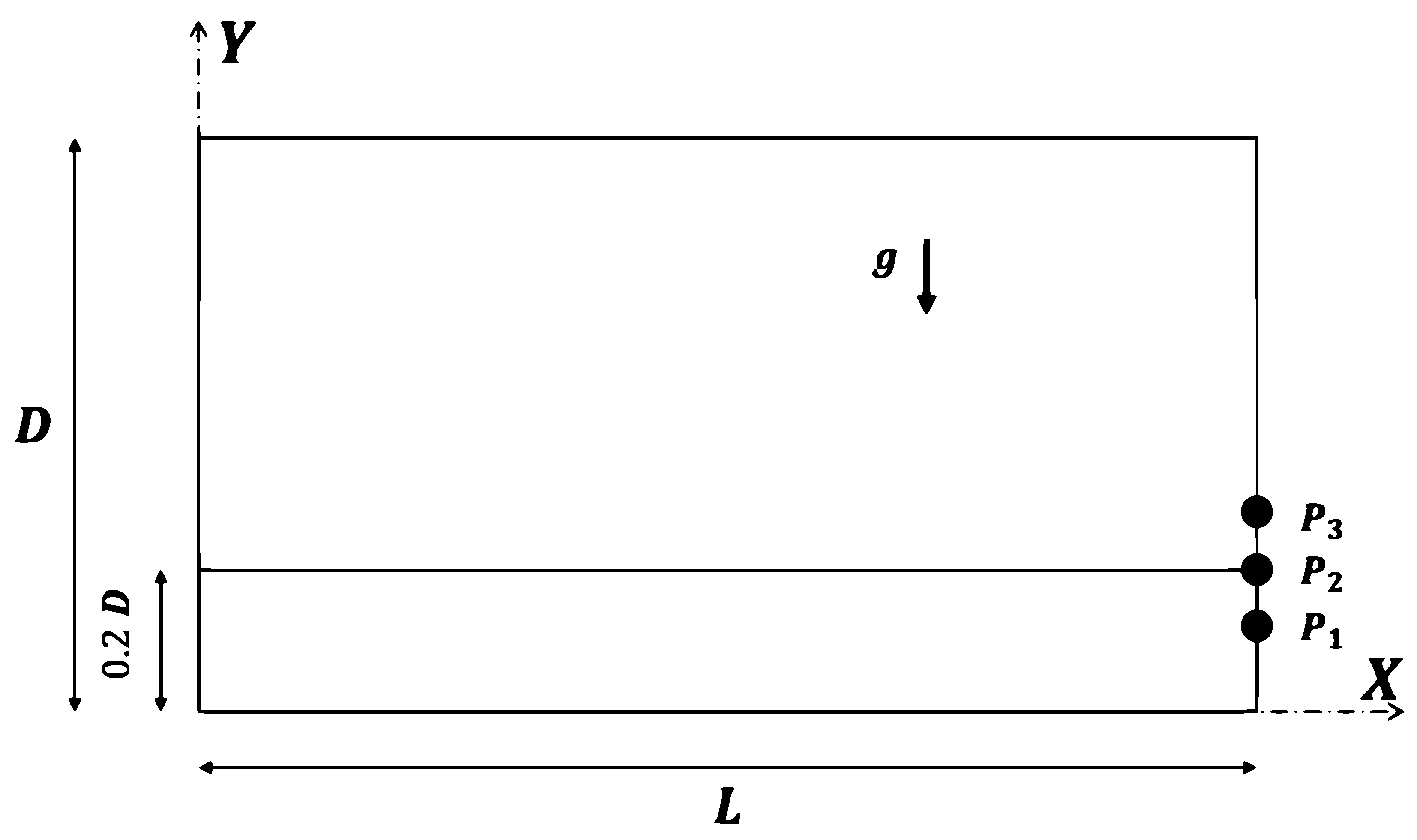
As it is illustrated in Figure 27, the initial configuration of the water sloshing in rectangular tank is presented. The same configuration as the experimental work of Rafiee et al. [80] is considered, when a rectangular tank of height D = 0.9 m and length of L = 1.3 m is partially filled with water to 20 % of its height D (i.e., H = 0.2 D = 0.18 m). The water flow is considered inviscid with a density of 1000 kg / m 3 , The gravity acceleration is taken as g = 0 , 9.81 T . The motion of tank is considered as a regular sinusoidal excitation along the horizontal direction (X-axis) with an amplitude of A 0 = 0.1 m and frequency f 0 = 0.496 Hrz that corresponds to the resonance frequency (i.e., x ˜ = A 0 sin ( 2 f 0 π t ) ). To record the pressure signals, three pressure probes P 1 , P 2 and P 3 located on the right wall of the tank respectively at the heights of 0.165 m, 0.18 m and 0.195 m from the bottom of the tank are used (see Figure 27).
In this work, a particle resolution of d x = L / 208 that corresponds to 5824 particles is considered for the simulation using our present particle shifting approach and that proposed by Wang et al. [37]. The initial pressure is taken as hydrostatic pressure. The velocity of the fluid is initialized by the same initial velocity of the tank as follows
u ( x , y , 0 ) = d x ˜ d t ( t = 0 ) , 0 T = 2 f 0 A 0 , 0 T
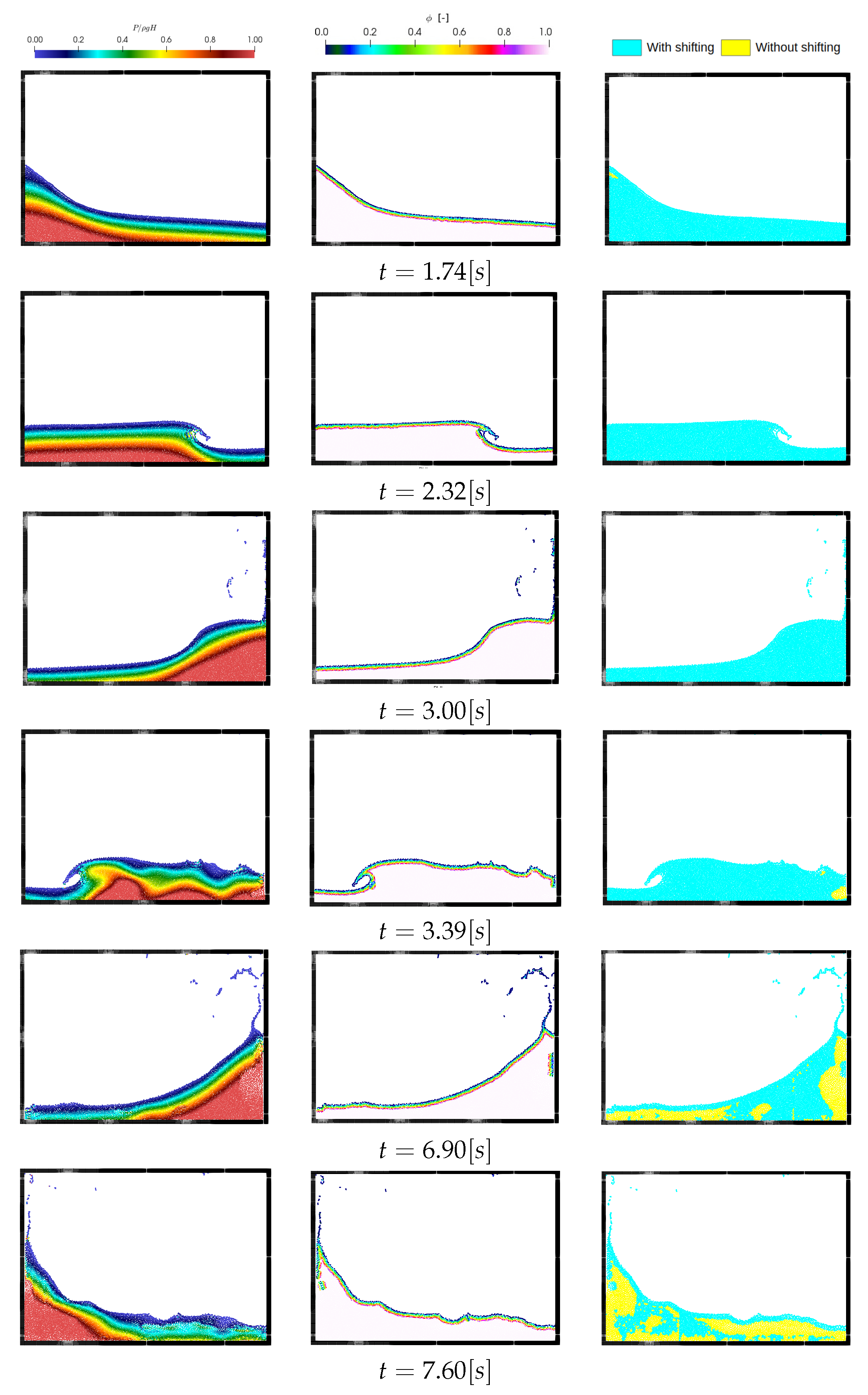
Figure 28 shows snapshots of the pressure field, ϕ parameter field and particle shifted regions at different times t = { 1.74 , 3.32 , 3.0 , 3.39 , 6.90 , 7.60 } s. The application of present particle shifting results a relatively smooth pressure filed at different times. We can also observe that the ϕ parameter is well defined, since it follows perfectly different regions of the fluid flow, and thus, it insures the correct application of the present particle shifting formulation. Via the third column of Figure 28, we show the application regions of the particle shifting technique.
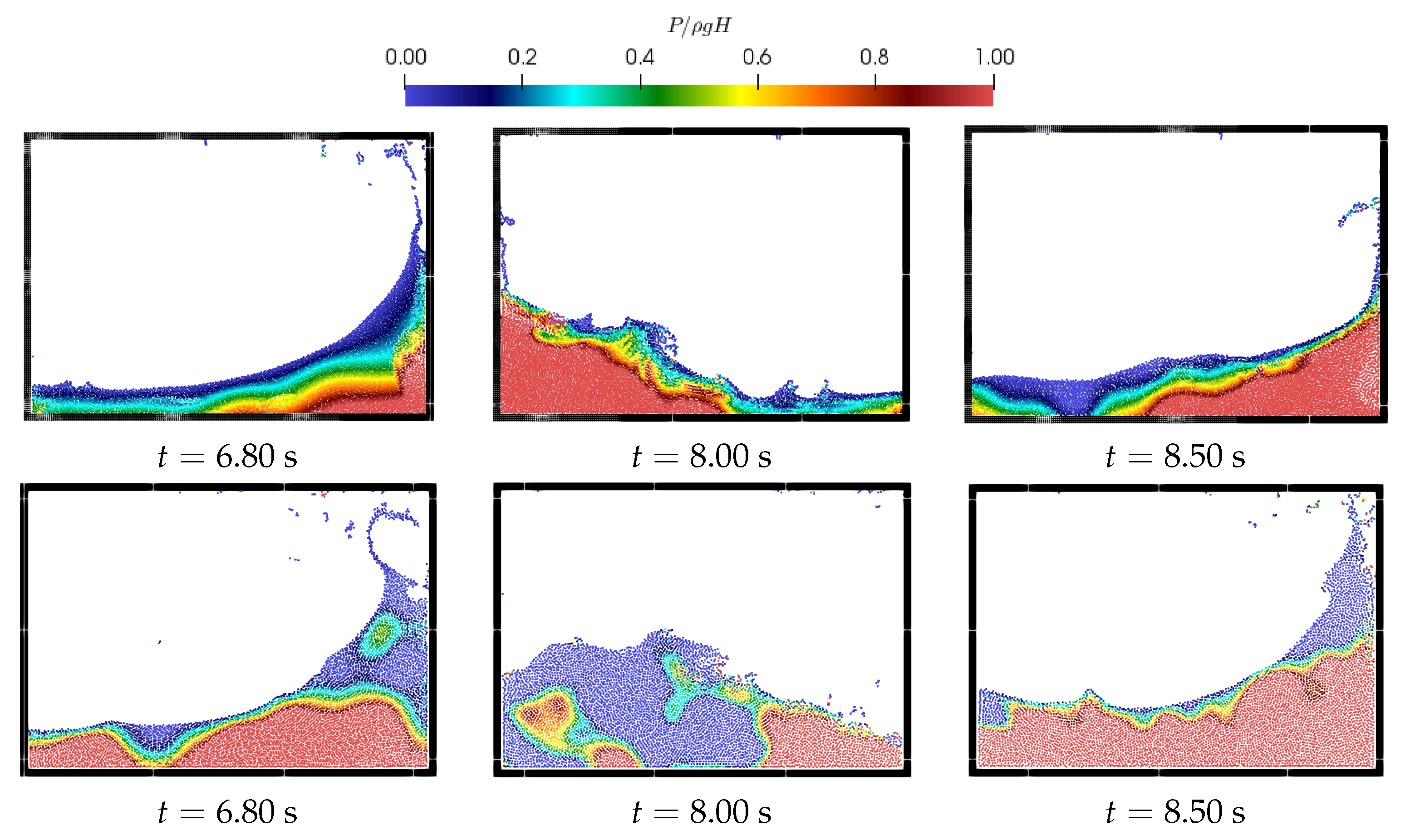
We compare via the Figure 29 at three different times t = { 6.80 , 8.00 , 8.50 } s, the pressure fields obtained by using the present particle shifting strategy and the improved particle shifting technique IPST developed by Wang et al. [37]. At these advanced times, the errors due to the continuous application of particle shifting strategy are highly accumulated, and thus will affect significantly the physics of the fluid flow. We can see that thanks to the application of particle shifting only in the region that meet our defined criterion (shifting applied only when ( C i > 0.98 )), the pressure filed are of fine smoothness comparing when we apply the IPST continuously without any limitation criterion. Furthermore, a non-physical dilatation of the total fluid volume is clearly visible in the second row of Figure 29 caused by the continuous application of the shifting.
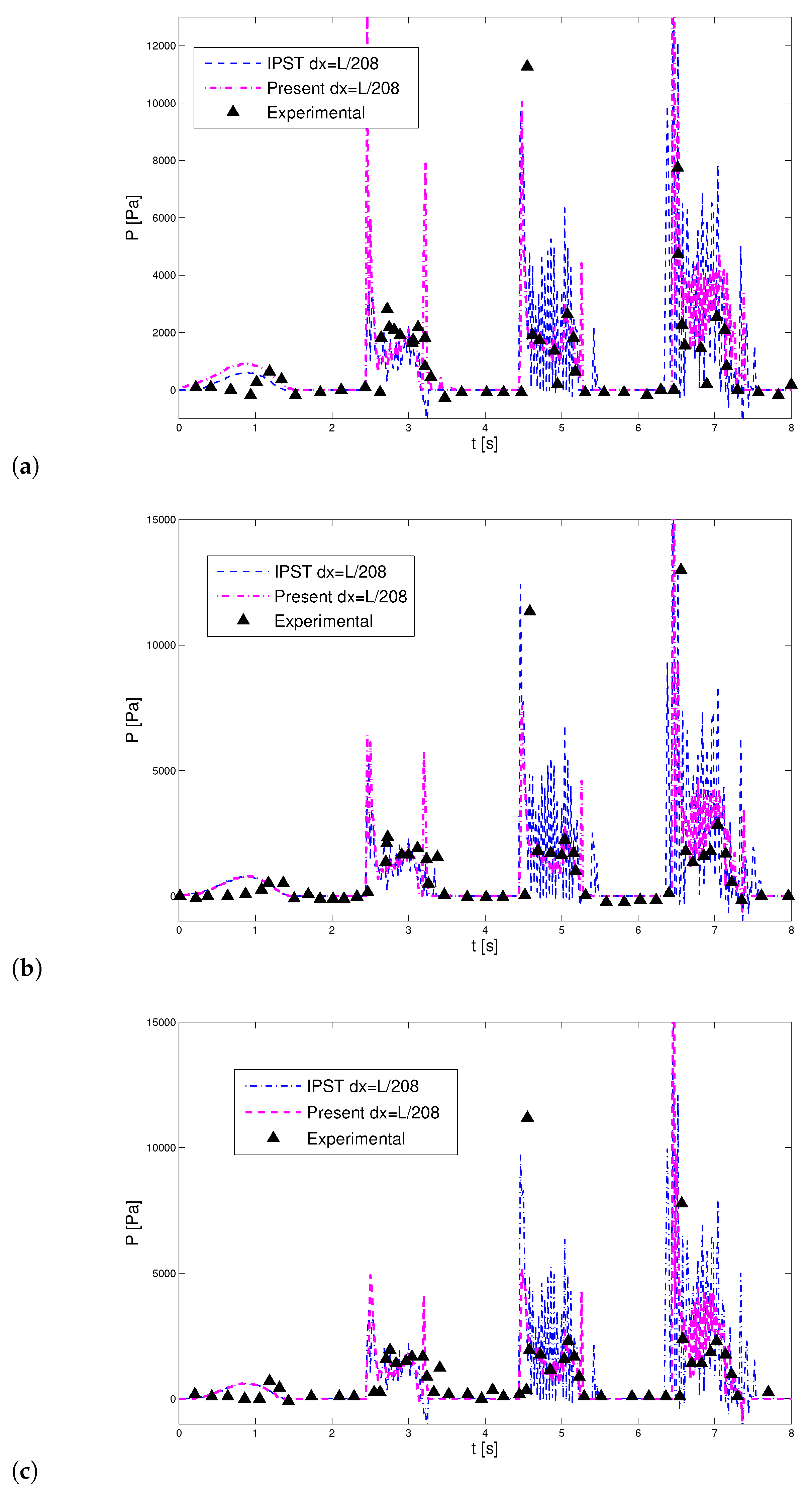
The time history of pressure signals recorded on the right vertical wall of the fluid tank at the positions P 1 , P 2 and P 3 are plotted in Figure 30. A good agreement in the overall behavior of the pressure between the present particle shifting technique and the experimental data [80] is noted along all the simulation. The peaks of pressure are overestimated by the numerical since the effect of entrapped air pockets is included in the experimental measurement. The pressure signals obtained by the continuous application of IPST [37] are of high oscillation frequency at advanced time and match less with the experimental data than our present approach. Such issue is produced because of the accumulated errors due to the particle shifting are significantly affect the overall flow physics as is shown previously in Figure 29. The noise presented in our pressure signals it may come naturally from the rapid dynamics of the highly violent fluid flows.
As it was already noted in the previous section, the non-physical dilation of fluid domain is caused by the continuous application of the particle shifting IPST. Thus, an application of criterion for deactivating the shifting where the particles expansion is occurred may overcome such issue.
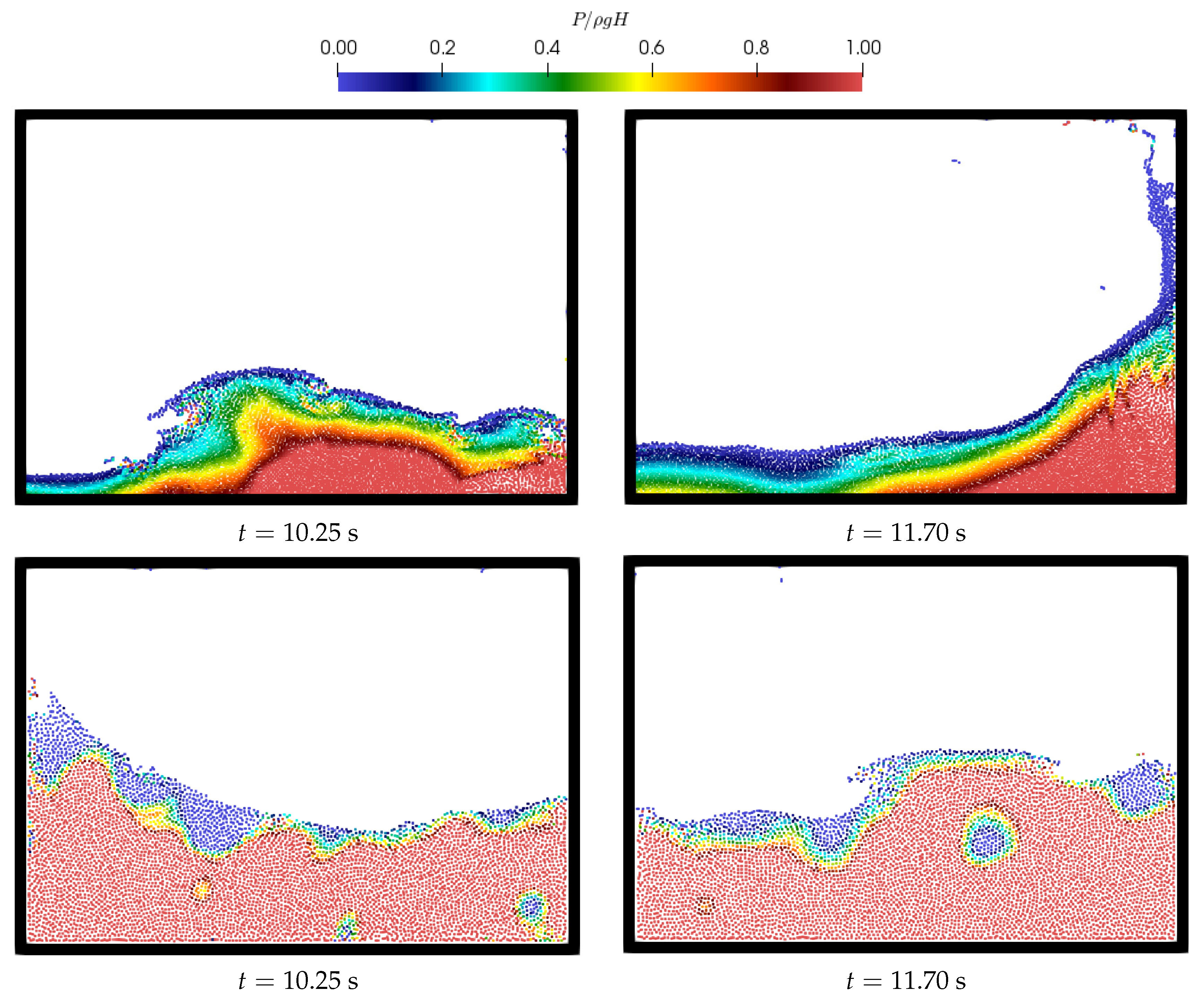
After reaching the 5th motion period of the sloshing tank, exactly at t = 10.25 s and t = 11.70 s, we present in Figure 31 the state of the flow within the tank obtained when our particle shifting approach and IPST [37] are used, The results obtained by our approach stay stable and show a correct physical behavior as expected. Nevertheless, when IPST is continuously applied to the particle positions, the fluid continues to expand and flows in a non-physical way and presents an unrealistic and unstable pressure field.

5. Conclusions

Through this work, an enhanced Particle Shifting strategy has been developed in the framework of weakly compressible δ + -SPH method. This technique can be considered as an extension of improved particle shifting technology (IPST) proposed by Wang et al. [37]. A new parameter ϕ is defined, on the one hand to reduce the effect of truncated kernel support on the formulation of the shifting particles near the free surface region, on the other hand, to deal with the problem of poor estimation of free surface particles. A simple criterion based on the estimation of particle concentration is also defined to limit the error’s accumulation in time caused by the shifting in order to achieve a long time violent free surface flows simulation. An efficient and simple concept for free surface particles detection has been also proposed via this paper.
The accuracy, stability of the present particle shifting strategy has been shown via four challenging benchmarks: Through the oscillating droplet under a central conservative force field and the evolution of initially-square fluid patch benchmarks, the superiority of our enhanced formulations of the particle shifting (PST) comparing to the one developed by Wang et al. [37] in terms of numerical proprieties and energy conservation are shown even when the free surface particles are poorly detected. Whereas for the two last benchmarks, the dam break flow and liquid sloshing flow in rectangular tank, it is demonstrated that the present approach with newly defined criterion can deal with violent free surface flows characterized by cyclic and high breaking wave events problems, which is considered as a weakness point for other particle shifting techniques.
Since our code is currently tow-dimensional, a validation of our present method in the context of 3D simulations will be considered in the future work. Furthermore, the application of our model in the case of a multi-phase and granular flows is targeted for future investigations.

Author Contributions

Conceptualization, A.K.; methodology, A.K. and M.J.; software, A.K.; validation, A.K., M.J. and A.S.; formal analysis, A.K.; investigation, A.K., M.J. and A.S.; resources, A.K., M.J. and A.S.; data curation, A.K., M.J. and A.S.; writing–original draft preparation, A.K., M.J. and A.S.; writing–review and editing, A.K., M.J. and A.S.; visualization, A.K.; supervision, A.S.; project administration, A.S.; funding acquisition, A.S. All authors have read and agreed to the published version of the manuscript.

Funding

This research was funded by the Canada Research Chair (CRC) program and Polytechnique Montreal, Canada.

Conflicts of Interest

The authors declare no conflict of interest.

References

  1. Gingold, R.A.; Monaghan, J.J. Smoothed particle hydrodynamics: Theory and application to non-spherical stars. Mon. Not. R. Astron. Soc. 1977, 181, 375–389. [Google Scholar] [CrossRef]
  2. Monaghan, J.J. Smoothed particle hydrodynamics and its diverse applications. Ann. Rev. Fluid Mech. 2012, 44, 323–346. [Google Scholar] [CrossRef]
  3. Ramírez, L.; Nogueira, X.; Khelladi, S.; Krimi, A.; Colominas, I. A very accurate Arbitrary Lagrangian– Eulerian meshless method for Computational Aeroacoustics. Comput. Methods Appl. Mech. Eng. 2018, 342, 116–141. [Google Scholar] [CrossRef] [Green Version]
  4. Tafuni, A.; Sahin, I. Hydrodynamic loads on vibrating cantilevers under a free surface in viscous fluids with SPH. In ASME International Mechanical Engineering Congress and Exposition; American Society of Mechanical Engineers: New York, NY, USA, 2013; Volume 56321, p. V07BT08A013. [Google Scholar]
  5. González-Cao, J.; Altomare, C.; Crespo, A.; Domínguez, J.; Gómez-Gesteira, M.; Kisacik, D. On the accuracy of DualSPHysics to assess violent collisions with coastal structures. Comput. Fluids 2019, 179, 604–612. [Google Scholar] [CrossRef]
  6. Mogan, S.C.; Chen, D.; Hartwig, J.; Sahin, I.; Tafuni, A. Hydrodynamic analysis and optimization of the Titan submarine via the SPH and Finite–Volume methods. Comput. Fluids 2018, 174, 271–282. [Google Scholar] [CrossRef]
  7. Verbrugghe, T.; Domínguez, J.M.; Altomare, C.; Tafuni, A.; Vacondio, R.; Troch, P.; Kortenhaus, A. Non-linear wave generation and absorption using open boundaries within DualSPHysics. Comput. Phys. Commun. 2019, 240, 46–59. [Google Scholar] [CrossRef]
  8. Domínguez, J.M.; Crespo, A.J.; Hall, M.; Altomare, C.; Wu, M.; Stratigaki, V.; Troch, P.; Cappietti, L.; Gómez-Gesteira, M. SPH simulation of floating structures with moorings. Coast. Eng. 2019, 153, 103560. [Google Scholar] [CrossRef]
  9. Kazemi, E.; Koll, K.; Tait, S.; Shao, S. SPH modelling of turbulent open channel flow over and within natural gravel beds with rough interfacial boundaries. Adv. Water Res. 2020, 140, 103557. [Google Scholar] [CrossRef]
  10. Krimi, A.; Rezoug, M.; Khelladi, S.; Nogueira, X.; Deligant, M.; Ramírez, L. Smoothed particle hydrodynamics: A consistent model for interfacial multiphase fluid flow simulations. J. Comput. Phys. 2018, 358, 53–87. [Google Scholar] [CrossRef] [Green Version]
  11. Krimi, A.; Khelladi, S.; Nogueira, X.; Deligant, M.; Ata, R.; Rezoug, M. Multiphase smoothed particle hydrodynamics approach for modeling soil–water interactions. Adv. Water Res. 2018, 121, 189–205. [Google Scholar] [CrossRef] [Green Version]
  12. Omidvar, P.; Kheirkhahan, M.; Hosseini, K. Simulation of two-phase Newtonian and non-Newtonian systems using smoothed particle hydrodynamics and herschel-bulkley model. J. Hydraul. 2019, 14, 19–33. [Google Scholar]
  13. Omidvar, P.; Nikeghbali, P. Simulation of violent water flows over a movable bed using smoothed particle hydrodynamics. J. Marine Sci. Technol. 2017, 22, 270–287. [Google Scholar] [CrossRef]
  14. Lo, E.Y.; Shao, S. Simulation of near-shore solitary wave mechanics by an incompressible SPH method. Appl. Ocean Res. 2002, 24, 275–286. [Google Scholar]
  15. Ataie-Ashtiani, B.; Shobeyri, G. Numerical simulation of landslide impulsive waves by incompressible smoothed particle hydrodynamics. Int. J. Numer. Methods Fluids 2008, 56, 209–232. [Google Scholar] [CrossRef]
  16. Fatehi, R.; Rahmat, A.; Tofighi, N.; Yildiz, M.; Shadloo, M.S. Density-based smoothed particle hydrodynamics methods for incompressible flows. Comput. Fluids 2019, 185, 22–33. [Google Scholar] [CrossRef]
  17. Nogueira, X.; Ramírez, L.; Clain, S.; Loubère, R.; Cueto-Felgueroso, L.; Colominas, I. High-accurate SPH method with multidimensional optimal order detection limiting. Comput. Methods Appl. Mech. Eng. 2016, 310, 134–155. [Google Scholar] [CrossRef] [Green Version]
  18. Vila, J. On particle weighted methods and smooth particle hydrodynamics. Math. Models Methods Appl. Sci. 1999, 9, 161–209. [Google Scholar] [CrossRef]
  19. Inutsuka, S.I. Reformulation of smoothed particle hydrodynamics with Riemann solver. J. Comput. Phys. 2002, 179, 238–267. [Google Scholar] [CrossRef] [Green Version]
  20. Zhang, C.; Hu, X.; Adams, N.A. A weakly compressible SPH method based on a low-dissipation Riemann solver. J. Comput. Phys. 2017, 335, 605–620. [Google Scholar] [CrossRef]
  21. Fourtakas, G.; Stansby, P.; Rogers, B.; Lind, S. An Eulerian–Lagrangian incompressible SPH formulation (ELI-SPH) connected with a sharp interface. Comput. Methods Appl. Mech. Eng. 2018, 329, 532–552. [Google Scholar] [CrossRef]
  22. Lind, S.J.; Stansby, P. High-order Eulerian incompressible smoothed particle hydrodynamics with transition to Lagrangian free-surface motion. J. Comput. Phys. 2016, 326, 290–311. [Google Scholar] [CrossRef]
  23. Marrone, S.; Antuono, M.; Colagrossi, A.; Colicchio, G.; Le Touzé, D.; Graziani, G. δ-SPH model for simulating violent impact flows. Comput. Methods Appl. Mech. Eng. 2011, 200, 1526–1542. [Google Scholar] [CrossRef]
  24. Meringolo, D.D.; Marrone, S.; Colagrossi, A.; Liu, Y. A dynamic δ-SPH model: How to get rid of diffusive parameter tuning. Comput. Fluids 2019, 179, 334–355. [Google Scholar] [CrossRef]
  25. Krimi, A.; Ramírez, L.; Khelladi, S.; Navarrina, F.; Deligant, M.; Nogueira, X. Improved δ-SPH Scheme with Automatic and Adaptive Numerical Dissipation. Water 2020, 12, 2858. [Google Scholar] [CrossRef]
  26. Monaghan, J.J. Smoothed particle hydrodynamics. Ann. Rev. Astron. Astrophys. 1992, 30, 543–574. [Google Scholar] [CrossRef]
  27. Antuono, M.; Colagrossi, A.; Marrone, S. Numerical diffusive terms in weakly-compressible SPH schemes. Comput. Phys. Commun. 2012, 183, 2570–2580. [Google Scholar] [CrossRef]
  28. Shadloo, M.S.; Oger, G.; Le Touzé, D. Smoothed particle hydrodynamics method for fluid flows, towards industrial applications: Motivations, current state, and challenges. Comput. Fluids 2016, 136, 11–34. [Google Scholar] [CrossRef]
  29. Swegle, J.; Hicks, D.; Attaway, S. Smoothed particle hydrodynamics stability analysis. J. Comput. Phys. 1995, 116, 123–134. [Google Scholar] [CrossRef]
  30. Monaghan, J.J. SPH without a tensile instability. J. Comput. Phys. 2000, 159, 290–311. [Google Scholar] [CrossRef]
  31. Oger, G.; Marrone, S.; Le Touzé, D.; De Leffe, M. SPH accuracy improvement through the combination of a quasi-Lagrangian shifting transport velocity and consistent ALE formalisms. J. Comput. Phys. 2016, 313, 76–98. [Google Scholar] [CrossRef]
  32. Antuono, M.; Bouscasse, B.; Colagrossi, A.; Marrone, S. A measure of spatial disorder in particle methods. Comput. Phys. Commun. 2014, 185, 2609–2621. [Google Scholar] [CrossRef]
  33. Matsunaga, T.; Koshizuka, S.; Hosaka, T.; Ishii, E. Moving surface mesh-incorporated particle method for numerical simulation of a liquid droplet. J. Comput. Phys. 2020, 409, 109349. [Google Scholar] [CrossRef]
  34. Sun, P.; Colagrossi, A.; Marrone, S.; Zhang, A. The δ-plus-SPH model: Simple procedures for a further improvement of the SPH scheme. Comput. Methods Appl. Mech. Eng. 2017, 315, 25–49. [Google Scholar] [CrossRef]
  35. Lind, S.J.; Xu, R.; Stansby, P.K.; Rogers, B.D. Incompressible smoothed particle hydrodynamics for free-surface flows: A generalised diffusion-based algorithm for stability and validations for impulsive flows and propagating waves. J. Comput. Phys. 2012, 231, 1499–1523. [Google Scholar] [CrossRef]
  36. Sun, P.; Colagrossi, A.; Marrone, S.; Antuono, M.; Zhang, A.M. A consistent approach to particle shifting in the δ-Plus-SPH model. Comput. Methods Appl. Mech. Eng. 2019, 348, 912–934. [Google Scholar] [CrossRef]
  37. Wang, P.P.; Meng, Z.F.; Zhang, A.M.; Ming, F.R.; Sun, P.N. Improved particle shifting technology and optimized free-surface detection method for free-surface flows in smoothed particle hydrodynamics. Comput. Methods Appl. Mech. Eng. 2019, 357, 112580. [Google Scholar] [CrossRef]
  38. Shao, S.; Lo, E.Y. Incompressible SPH method for simulating Newtonian and non-Newtonian flows with a free surface. Adv. Water Res. 2003, 26, 787–800. [Google Scholar] [CrossRef]
  39. Shao, S. Incompressible SPH simulation of wave breaking and overtopping with turbulence modelling. Int. J. Numer. Methods Fluids 2006, 50, 597–621. [Google Scholar] [CrossRef]
  40. Khayyer, A.; Gotoh, H.; Shao, S. Corrected incompressible SPH method for accurate water-surface tracking in breaking waves. Coast. Eng. 2008, 55, 236–250. [Google Scholar] [CrossRef] [Green Version]
  41. Khayyer, A.; Gotoh, H.; Shao, S. Enhanced predictions of wave impact pressure by improved incompressible SPH methods. Appl. Ocean Res. 2009, 31, 111–131. [Google Scholar] [CrossRef] [Green Version]
  42. Khayyer, A.; Gotoh, H. Modified moving particle semi-implicit methods for the prediction of 2D wave impact pressure. Coast. Eng. 2009, 56, 419–440. [Google Scholar] [CrossRef]
  43. Schwaiger, H.F. An implicit corrected SPH formulation for thermal diffusion with linear free surface boundary conditions. Int. J. Numer. Methods Eng. 2008, 75, 647–671. [Google Scholar] [CrossRef]
  44. Lee, E.S.; Moulinec, C.; Xu, R.; Violeau, D.; Laurence, D.; Stansby, P. Comparisons of weakly compressible and truly incompressible algorithms for the SPH mesh free particle method. J. Comput. Phys. 2008, 227, 8417–8436. [Google Scholar] [CrossRef]
  45. Marrone, S.; Colagrossi, A.; Le Touzé, D.; Graziani, G. Fast free-surface detection and level-set function definition in SPH solvers. J. Comput. Phys. 2010, 229, 3652–3663. [Google Scholar] [CrossRef]
  46. Barecasco, A.; Terissa, H.; Naa, C.F. Simple free-surface detection in two and three-dimensional SPH solver. arXiv 2013, arXiv:1309.4290. [Google Scholar]
  47. Jandaghian, M.; Shakibaeinia, A. An enhanced weakly-compressible MPS method for free-surface flows. Comput. Methods Appl. Mech. Eng. 2020, 360, 112771. [Google Scholar] [CrossRef]
  48. Monaghan, J.J. Simulating free surface flows with SPH. J. Comput. Phys. 1994, 110, 399–406. [Google Scholar] [CrossRef]
  49. Morris, J.P. Simulating surface tension with smoothed particle hydrodynamics. Int. J. Numer. Methods Fluids 2000, 33, 333–353. [Google Scholar] [CrossRef]
  50. Liu, M.; Liu, G.; Lam, K. Constructing smoothing functions in smoothed particle hydrodynamics with applications. J. Comput. Appl. Math. 2003, 155, 263–284. [Google Scholar] [CrossRef] [Green Version]
  51. Wendland, H. Piecewise polynomial, positive definite and compactly supported radial functions of minimal degree. Adv. Comput. Math. 1995, 4, 389–396. [Google Scholar] [CrossRef]
  52. Dehnen, W.; Aly, H. Improving convergence in smoothed particle hydrodynamics simulations without pairing instability. Mon. Not. R. Astron. Soc. 2012, 425, 1068–1082. [Google Scholar] [CrossRef] [Green Version]
  53. Sun, P.; Colagrossi, A.; Marrone, S.; Antuono, M.; Zhang, A. Multi-resolution Delta-plus-SPH with tensile instability control: Towards high Reynolds number flows. Comput. Phys. Commun. 2018, 224, 63–80. [Google Scholar] [CrossRef]
  54. Antuono, M.; Colagrossi, A.; Marrone, S.; Molteni, D. Free-surface flows solved by means of SPH schemes with numerical diffusive terms. Comput. Phys. Commun. 2010, 181, 532–549. [Google Scholar] [CrossRef]
  55. Williamson, J. Low-storage runge-kutta schemes. J. Comput. Phys. 1980, 35, 48–56. [Google Scholar] [CrossRef]
  56. Monaghan, J.J. Smoothed particle hydrodynamics. Rep. Prog. Phys. 2005, 68, 1703. [Google Scholar] [CrossRef]
  57. Adami, S.; Hu, X.Y.; Adams, N.A. A generalized wall boundary condition for smoothed particle hydrodynamics. J. Comput. Phys. 2012, 231, 7057–7075. [Google Scholar] [CrossRef]
  58. Khayyer, A.; Gotoh, H.; Shimizu, Y. Comparative study on accuracy and conservation properties of two particle regularization schemes and proposal of an optimized particle shifting scheme in ISPH context. J. Comput. Phys. 2017, 332, 236–256. [Google Scholar] [CrossRef]
  59. Meringolo, D.; Colagrossi, A.; Marrone, S.; Aristodemo, F. On the filtering of acoustic components in weakly-compressible SPH simulations. J. Fluids Struct. 2017, 70, 1–23. [Google Scholar] [CrossRef]
  60. Monaghan, J.J.; Rafiee, A. A simple SPH algorithm for multi-fluid flow with high density ratios. Int. J. Numer. Methods Fluids 2013, 71, 537–561. [Google Scholar] [CrossRef]
  61. Le Touzé, D.; Colagrossi, A.; Colicchio, G.; Greco, M. A critical investigation of smoothed particle hydrodynamics applied to problems with free-surfaces. Int. J. Numer. Methods Fluids 2013, 73, 660–691. [Google Scholar] [CrossRef]
  62. Dormand, J.R.; Prince, P.J. A family of embedded Runge-Kutta formulae. J. Comput. Appl. Math. 1980, 6, 19–26. [Google Scholar] [CrossRef] [Green Version]
  63. Zheng, X.; Shao, S.; Khayyer, A.; Duan, W.; Ma, Q.; Liao, K. Corrected first-order derivative ISPH in water wave simulations. Coast. Eng. J. 2017, 59, 1750010. [Google Scholar] [CrossRef]
  64. Colagrossi, A. A Meshless Lagrangian Method for Free-Surface and Interface Flows with Fragmentation. Ph.D. Thesis, University Roma, Roma, Italy, 2005; pp. 1–234. [Google Scholar]
  65. Khayyer, A.; Gotoh, H. Enhancement of stability and accuracy of the moving particle semi-implicit method. J. Comput. Phys. 2011, 230, 3093–3118. [Google Scholar] [CrossRef]
  66. Oger, G.; Doring, M.; Alessandrini, B.; Ferrant, P. An improved SPH method: Towards higher order convergence. J. Comput. Phys. 2007, 225, 1472–1492. [Google Scholar] [CrossRef]
  67. Martin, J.C.; Moyce, W.J.; Martin, J.; Moyce, W.; Penney, W.G.; Price, A.; Thornhill, C. Part IV. An experimental study of the collapse of liquid columns on a rigid horizontal plane. Philos. Trans. R. Soc. Lond. Ser. A Math. Phys. Sci. 1952, 244, 312–324. [Google Scholar]
  68. Zhou, Z.; De Kat, J.; Buchner, B. A nonlinear 3D approach to simulate green water dynamics on deck. In Proceedings of the Seventh International Conference on Numerical Ship Hydrodynamics, Nantes, France, 19–22 July 1999; pp. 1–15. [Google Scholar]
  69. Buchner, B. Green Water on Ship-Type Offshore Structures. Ph.D. Thesis, Delft University of Technology, Delft, The Netherlands, 2002. [Google Scholar]
  70. Colagrossi, A.; Landrini, M. Numerical simulation of interfacial flows by smoothed particle hydrodynamics. J. Comput. Phys. 2003, 191, 448–475. [Google Scholar] [CrossRef]
  71. Mokos, A.; Rogers, B.D.; Stansby, P.K.; Domínguez, J.M. Multi-phase SPH modelling of violent hydrodynamics on GPUs. Comput. Phys. Commun. 2015, 196, 304–316. [Google Scholar] [CrossRef]
  72. Chen, Z.; Zong, Z.; Liu, M.; Zou, L.; Li, H.; Shu, C. An SPH model for multiphase flows with complex interfaces and large density differences. J. Comput. Phys. 2015, 283, 169–188. [Google Scholar] [CrossRef]
  73. Zhang, T.; Koshizuka, S.; Xuan, P.; Li, J.; Gong, C. Enhancement of stabilization of MPS to arbitrary geometries with a generic wall boundary condition. Comput. Fluids 2019, 178, 88–112. [Google Scholar] [CrossRef]
  74. Greco, M. A Two-Dimensional Study of Green-Water Loading. Ph.D. Thesis, Norwegian University of Science and Technology, Trondheim, Norway, 2001. [Google Scholar]
  75. Cherfils, J.M. Développements et Applications de la Méthode SPH Aux écoulements Visqueux à Surface Libre. Ph.D. Thesis, CNRS-Université du Havre, Le Havre, France, 2011. [Google Scholar]
  76. Ritter, A. Die fortpflanzung der wasserwellen. Z. Ver. Dtsch. Ing. 1892, 36, 947–954. [Google Scholar]
  77. Rezavand, M.; Zhang, C.; Hu, X. A weakly compressible SPH method for violent multi-phase flows with high density ratio. J. Comput. Phys. 2020, 402, 109092. [Google Scholar] [CrossRef] [Green Version]
  78. Bellezi, C.A.; Cheng, L.Y.; Okada, T.; Arai, M. Optimized perforated bulkhead for sloshing mitigation and control. Ocean Eng. 2019, 187, 106171. [Google Scholar] [CrossRef]
  79. ARAI, M.; Hata, R.; Cheng, L.Y. Sloshing in vertical and horizontal axisymmetric tanks. J. Jpn. Soc. Naval Arch. Ocean Eng. 2018, 27, 117–123. [Google Scholar] [CrossRef]
  80. Rafiee, A.; Pistani, F.; Thiagarajan, K. Study of liquid sloshing: Numerical and experimental approach. Comput. Mech. 2011, 47, 65–75. [Google Scholar] [CrossRef]
  81. Cao, X.; Ming, F.; Zhang, A. Sloshing in a rectangular tank based on SPH simulation. Appl. Ocean Res. 2014, 47, 241–254. [Google Scholar] [CrossRef]
  82. Winkler, D.; Meister, M.; Rezavand, M.; Rauch, W. gpuSPHASE—A shared memory caching implementation for 2D SPH using CUDA. Comput. Phys. Commun. 2017, 213, 165–180. [Google Scholar] [CrossRef]
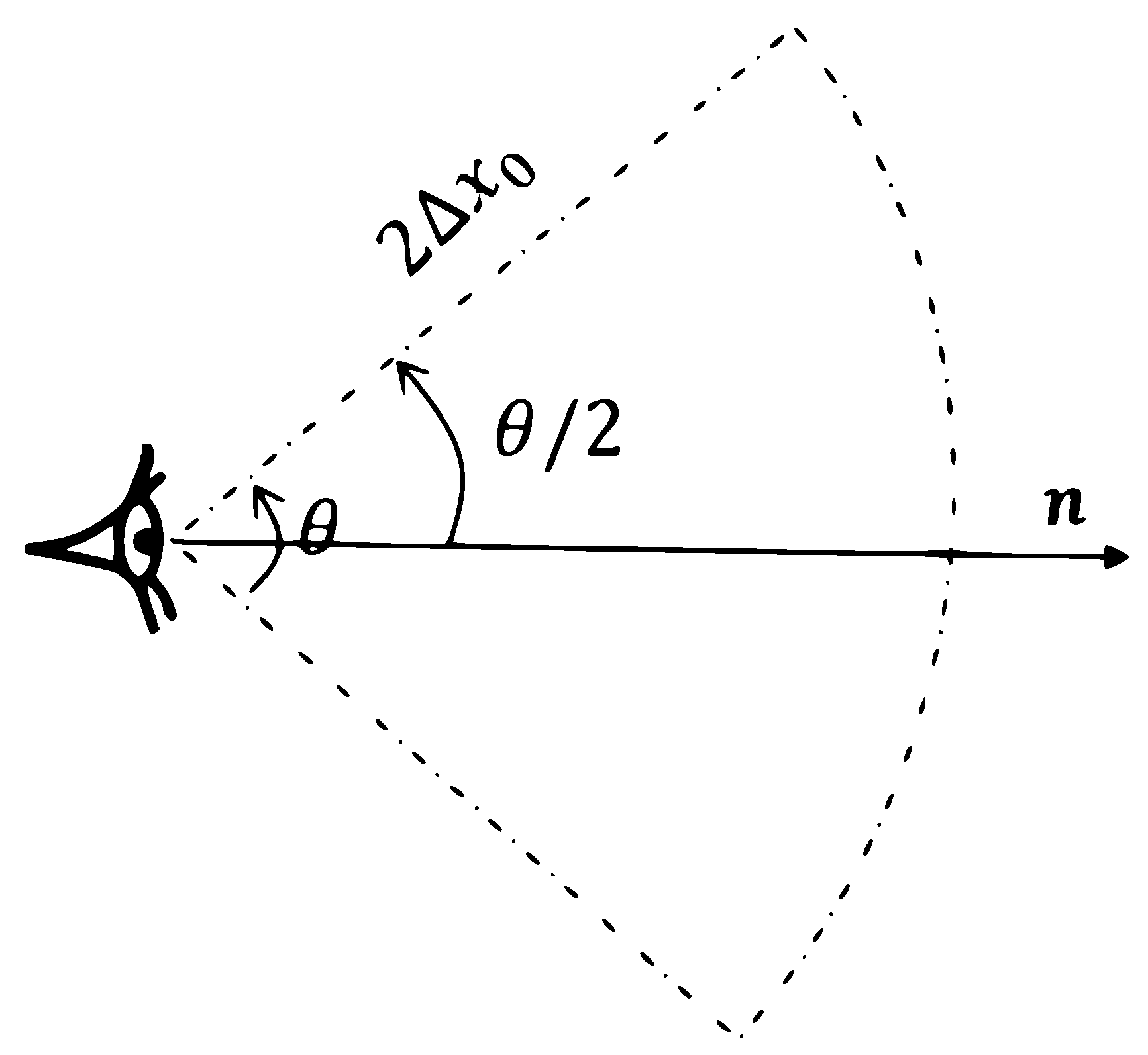
Figure 1. Free surface particle detection concept. θ is the angle of vision and 2 Δ x 0 is the vision distance. Where Δ x 0 denotes the initial particle spacing.
Water 12 03189 g001
Figure 2. Principals of the free surface particles detection, Step 1 presents the free surface particles detection conditions and Step 3 presents the definition of inner particles near to the free surface particles.
Water 12 03189 g002
Figure 3. The free surface particles detected for the dam-break example. The free surface particle of the fluid are colored with black color ( D F S ), whereas for the particle colored with yellow and green colors represent respectively, the inner particle near ( D I F S ) and far ( D I N ) from the free surface region. The first row (a) shows the results via the method proposed by Marrone et al. [45], while the rows (b,c) represent the results using Jandaghian and Shakibaeinia [47] and the present approaches, respectively.
Water 12 03189 g003
Figure 4. Different parameters used to define ϕ for particle i as r i D I F S .
Water 12 03189 g004
Figure 5. Oscillating droplet under a central conservative force field. R is the raduis of the intial circular drop, a and b are the semi-major and semi-minor axis of the evolving ellipse, respectively.
Water 12 03189 g005
Figure 6. Oscillating droplet under a central conservative force field: Pressure and the dimensionless parameter ϕ evolution in time. The right half of the droplet is colored by the pressure field, and the left half is colored by the ϕ paremeter field.
Water 12 03189 g006
Figure 7. Oscillating droplet under a central conservative force field: The particle are colored with pressure and dimensionless ϕ - parameter on the left and the right half of the fluid droplet, respectively at the time t = 2.44 s. (a) under the resolution of d x = R 100 in the snapshot (a) and d x = R 50 in (b). The snapshot (c) shows a zoom on the ϕ field obtained through the selected red rectangle of the snapshot (b).
Water 12 03189 g007
Figure 8. Oscillating droplet under a central conservative force field: horizontal semi major axis evolution in time a ( t ) . The black solid line presents the theoretical results obtained by solving the system (18) [60]. The red dotted line represents the results obtained by the present particle shifting formulation for the fluid droplet of resolution d x = R 50 , whereas for the magenta dash-dot line is for d x = R 100 . The blue dashed line represents the results obtained by the particle shifting technology (IPST) proposed by Wang et al. [37]. The bottom part (b) of the figure represents the zoom of selected red rectangle in (a).
Water 12 03189 g008
Figure 9. Oscillating droplet under a central conservative force field: Vertical semi minor axis evolution in time b ( t ) . The black solid line presents the theoretical results obtained by solving the system (18) [60]. The red dotted line represents the results obtained by the present particle shifting formulation for the fluid droplet of resolution d x = R 50 , whereas for the magenta dash-dot line is for d x = R 100 . The blue dashed line represents the results obtained by the particle shifting technology (IPST) proposed by Wang et al. [37]. The bottom part (b) of the figure represents the zoom of selected red rectangle in (a).
Water 12 03189 g009
Figure 10. Oscillating droplet under a central conservative force field: Kinetic energy evolution in time E k ( t ) . The black solid line presents the theoretical results obtained by solving the system (18) [60]. The red dotted line represents the results obtained by the present particle shifting formulation for the fluid droplet of resolution d x = R 50 , whereas for the magenta dash-dot line is for d x = R 100 . The blue dashed line represents the results obtained by the particle shifting technology (IPST) proposed by Wang et al. [37]. The bottom part (b) of the figure represents the zoom of selected red rectangle in (a).
Water 12 03189 g010
Figure 11. Oscillating droplet under a central conservative force field: Potential Energy evolution in time E p ( t ) . The black solid line presents the theoretical results obtained by solving the system (18) [60]. The red dotted line represents the results obtained by the present particle shifting formulation for the fluid droplet of resolution d x = R 50 , whereas for the magenta dash-dot line is for d x = R 100 . The blue dashed line represents the results obtained by the particle shifting technology (IPST) proposed by Wang et al. [37]. The bottom part (b) of the figure represents the zoom of selected red rectangle in (a).
Water 12 03189 g011
Figure 12. Oscillating droplet under a central conservative force field: Total energy evolution in time E T ( t ) . The black solid line presents the theoretical results obtained by solving the system (18) [60]. The red dotted line represents the results obtained by the present particle shifting formulation for the fluid droplet of resolution d x = R 50 , whereas for the magenta dash-dot line is for d x = R 100 . The blue dashed line represents the results obtained by the particle shifting technology (IPST) proposed by Wang et al. [37].
Water 12 03189 g012
Figure 13. Oscillating droplet under a central conservative force field: Convergence studies with present SPH and δ -SPH [23] schemes. The dotted line with small circles denotes the convergence curve of the δ -SPH scheme and the dotted line with small squares denotes the convergence curve of the present SPH model. The dashed and continues lines represent 1 st and 2 nd order of convergence slops, respectively.
Water 12 03189 g013
Figure 14. Evolution of an initially-square fluid patch: initial configuration.
Water 12 03189 g014
Figure 15. Evolution of an initially-square fluid patch: Pressure field obtained at dimentionless times t ω = { 0.6 , 1.2 , 2.04 } . The black bold points present the free surface evaluated by the Lagrangian Finite Difference Method [61].
Water 12 03189 g015
Figure 16. Evolution of an initially-square fluid patch: Pressure field obtained and evolving shape of the square path at dimensionless times t ω = { 6 , 8 , 9.5 } .
Water 12 03189 g016
Figure 17. Evolution of an initially-square fluid patch: The fluid particles distribution at the dimensionless time t ω = 2.2 . The left column presents the results obtained by using our particle shifting approach (here a poor detection free surface is presented), whereas for the right column shows the results obtained using by using IPST [37]. The three last rows of the figure present the zooms on the three selected regions.
Water 12 03189 g017
Figure 18. Evolution of an initially-square fluid patch: The fluid particles distribution at the dimensionless time t ω = 2.2 in the case of poor detection free surface. The particles are colored with dimensionless ϕ -parameter field. The second row presents the zooms on the three selected regions.
Water 12 03189 g018
Figure 19. Evolution of an initially-square fluid patch: Time evolution of the pressure at the center of the fluid path. The red dotted line represents the results obtained by the present particle shifting formulation for the particle resolution of d x = L 100 , whereas for the magenta dash-dot line, it corresponds to the particle resolution of d x = L 200 . The black dotted line with diamond marker denotes the pressure results obtained by BEM-MEL solver [61]. The second row of the figure presents a zoom region.
Water 12 03189 g019aWater 12 03189 g019b
Figure 20. Evolution of an initially-square fluid patch: Dissipation of the kinetic energy. The red dotted line presents the results obtained by the present particle shifting formulation for the particle resolution of d x = L 100 , The blue dashed line represents the results obtained by using IPST [37] for the particle resolution of d x = L 100 . whereas for the magenta dash-dot line presents the results obtained by the present particle shifting formulation for the particle resolution of d x = L 200 .
Water 12 03189 g020
Figure 21. Dam break flow: problem configuration.
Water 12 03189 g021
Figure 22. Dam break flow: Snapshots of the computational results at dimensionless times t g / H = { 1.61 , 5.45 , 6.14 , 10.24 , 20.02 } . The left column presents the pressure field, the middle column denotes the ϕ -parameter field and the right column presents the restriction field (no shifting is applied on the yellow region).
Water 12 03189 g022
Figure 23. Dam break flow: Snapshots of pressure field at dimensionless times t g / H = { 6.00 , 14.80 , 20.03 } , The left column depicts the results obtained by the present method. The right column presents the results obtained with IPST [37]. The solid magenta line shows the position of final free surface at equilibrium, should the total volume conserve.
Water 12 03189 g023
Figure 24. Dam break flow: time evolution of the water front, the green solid line presents the analytical solution from shallow water theory [76], The black triangles denotes the experimental data given by Buchner [69]. The blue dash-dot line represents the results obtained by using IPST [37], whereas for the magenta dashed line presents the results obtained by the present particle shifting formulation.
Water 12 03189 g024
Figure 25. Dam break flow: History of the pressure signals recorded at P. The black triangles denotes the experimental data given by Buchner [69]. The blue dash-dot line represents the results obtained by using IPST [37], whereas for the magenta dashed line presents the results obtained by the present particle shifting formulation.
Water 12 03189 g025
Figure 26. Dam break flow: Time evolution of mechanical energy. The blue dash-dot line represents the results obtained by using IPST [37], whereas for the magenta dashed line presents the results obtained by the present particle shifting formulation. The black reference curve is taken from Marrone et al. [23].
Water 12 03189 g026
Figure 27. Sloshing in a rectangular tank: initial configuration.
Water 12 03189 g027
Figure 28. Sloshing in a rectangular tank: Snapshots of the computational results at times t = { 1.74 , 2.32 , 3.00 , 3.99 , 6.90 , 7.60 } s. The left column presents the pressure filed, the middle column denotes the ϕ -parameter filed and the right column presents the restriction field (no shifting is applied on the yellow region).
Water 12 03189 g028
Figure 29. Sloshing in a rectangular tank: Snapshots of pressure field at times t = { 6.80 , 8.00 , 8.50 } s, The first row depicts the results obtained by the present method. The second row presents the results obtained with IPST [37].
Water 12 03189 g029
Figure 30. Sloshing in a rectangular tank: time history of the impact pressure at the three installed probes P 1 , P 2 and P 3 . figures (ac) present the comparison between the present numerical and experimental pressure signals obtained at the probes P 1 , P 2 and P 3 , respectively. The black triangles denotes the experimental data given by Rafiee et al. [80]. The blue dashed line represents the results obtained by using IPST [37], whereas for the magenta dash-dot line presents the results obtained by the present particle shifting formulation.
Water 12 03189 g030
Figure 31. Sloshing in a rectangular tank: Snapshots of pressure field at times t = 10.25 s and t = 11.70 s. The first row depicts the results obtained by the present method. The second row presents the results obtained with IPST [37].
Water 12 03189 g031
Table 1. Dam break flow: comparison table of the computational times using our present particle shifting formulation and IPST [37] for simulating 5 s of the dam break physical time under 12,800 particles.
Particle Shifting ModelComputational Time in s
Present particle shifting formulation6813
IPST [37]6608
Publisher’s Note: MDPI stays neutral with regard to jurisdictional claims in published maps and institutional affiliations.