Abstract
An independent field performance evaluation for a secondary stormwater filtration device, named the Ecosol Strom Pit (Class 2), was performed between May 2017 and July 2019 in an urban catchment in Queensland, Australia. During the testing period, a total of 37 rainfall events were recorded, of which between 15 and 21 events were evaluated as qualifying for the purposes of characterizing the removal efficiency performance of the device. A statistical analysis of the event mean concentrations (EMCs) of the flow streams through the device indicate a statistically significant difference between the influent and effluent streams. A variety of pollutant removal evaluation metrics, including concentration-based and total load-based metrics, were utilized in this study to characterise the efficacy of the device. Two new approaches are proposed for facilitation the analysis: a nonlinear regression approach to more effectively deal with nonlinear patterns in the influent and effluent data and the regression of concentration (ROC), which is an added concentration-based metrics. In summary, the removal efficiencies of the Ecosol Storm Pit (Class 2) were evaluated to be 72–74% for total suspended solids (TSS), 45–50% for total phosphorus (TP), 41–45% for total nitrogen (TN), 27–32% for total heavy metals (THM), 79–85% for total petroleum hydrocarbons (TPH), and 80–88% for total recoverable hydrocarbons (TRH).
1. Introduction
Within current day Australia, larger scale urban developments require the incorporation of water-sensitive urban design (WSUD) objectives and principles to minimize the impact urban development has on the natural water cycle by protecting natural ecosystems and their water quality [1]. WSUD best environmental management practices typically require planners and developers to apply a “fit for purpose” approach to stormwater treatment measures, which often requires a treatment train approach, as no individual treatment measure adequately treats the full range of pollutants contained within the run-off from typical urban developments. Treatment measures reduce the concentration of a range of pollutants, thereby enhancing water quality. The objectives of the field study were to verify the pollutant removal capabilities of the Ecosol Storm Pit (Class 2).
The Ecosol Storm Pit (Class 2) is a unique compact at-source or in-line secondary stormwater filtration system, designed to carry out multiple treatment processes on stormwater runoff within the one compact underground device [2]. The unit consists of a primary treatment inlet litter basket, designed to capture and retain all particles larger than 200 microns, as well as a unique patented multi-barrier media filter for secondary treatment. Due to the multi-barrier media, the Ecosol Storm Pit (Class 2) uses various physical, chemical and biological pollutant removal mechanisms to filter contaminants normally found in stormwater runoff, namely, polypropylene for fine solids, oils and grease, conditioned clinoptilolite for positively charged dissolved contaminants, and laterite for negatively charged dissolved contaminants.
The multi-barrier filter bed, as well as its three specific filter materials, have been trialed in water, wastewater, and stormwater treatment applications around the world. A stormwater treatment device packed with porous polypropylene media was trialed in Otsu, Shiga-Japan [3]. Eight rainfall events were monitored with the total rainfall and maximum intensity ranging from 7 to 51 mm and from 2 to 10 mm/h, respectively. The mean removal efficiency for pollutants studied was 92% for suspended solids (SS), 72% for chemical oxygen demand (COD), 44% for TP, and above 70% and 60% for the heavy metals and polycyclic hydrocarbons (PAHs), respectively [3]. A clinoptilolite cartridge filter was trialed in the Garching campus of the Technical University of Munich, Germany, treating the runoff from an 11-year-old zinc roof [4]. Samples of 24 rain events were examined and zinc was detected in the roof runoff in concentrations of up to 25 mg/L. The clinoptilolite filter was able to remove up to 97% of the zinc from the roof runoff [4]. Athanasiadis et al. [5] presented results from a field trial of GHD’s StormDMTTM device (a patented design of the aforementioned multi-barrier), treating stormwater runoff generated at a bulk storage facility in the Port of Townsville, Australia. The StormDMTTM multi-barrier filter achieved a concentration removal efficiency (CRE) of approximately 80% for total lead and 76% for total zinc.
The device was installed in April 2017 and the stormwater filtration monitoring began in May 2017 and was completed in July 2019. This paper reports on the filtration performance analysis findings from this field study.
2. Materials and Methods
2.1. Site and Filtration Device Details
An appropriate site was selected by Urban Asset Solutions Pty Ltd. (Adelaide, Australia) to install the Ecosol Storm Pit (Class 2) for monitoring and testing. Testing was undertaken in accordance with the “Stormwater Quality Improvement Device Evaluation Protocol” (SQIDEP) [6]. The monitoring and verification of testing methodologies and site evaluation were developed by authors. The site is located in the Redlands City Depot, Queensland. The location of the unit was at the most extreme downstream point for the catchment of interest to give the best representation of the site for monitoring [7]. The area contributing runoff to the Ecosol Storm Pit (Class 2), consisted of approximately 120 m2 of roof considered 100% impervious, 240 m2 asphalt-paved considered 90% impervious, and 860 m2 mixed with 70% imperviousness. The total area of the site is almost 1220 m2 with an average of 77% impervious covering. Figure 1a and Figure 2 show the layout of the catchment, including the stormwater drainage network and the installed Ecosol Strom Pit (Class 2).
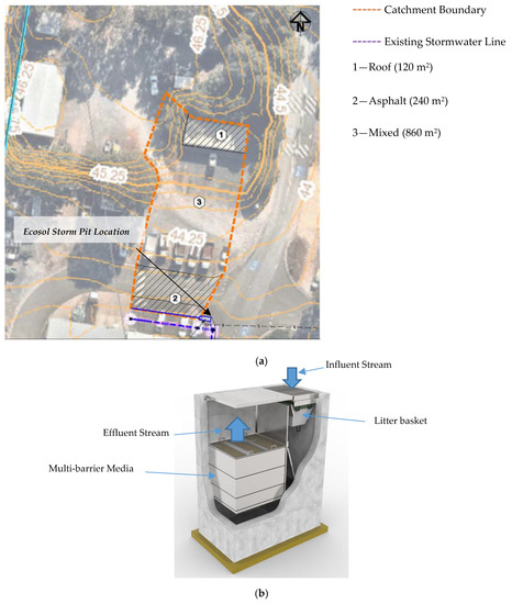
Figure 1.
(a) Existing site layout and catchment plan [8]; (b) Ecosol Storm Pit (Class 2) [3].
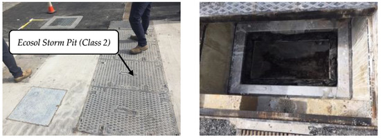
Figure 2.
Installed Ecosol Storm Pit (Class 2).
A schematic of the Ecosol Storm Pit (Class 2) is given in Figure 1b. The Ecosol Storm Pit (Class 2) is an all-in-one primary and secondary filtration system that helps overcome the need for multiple treatment measures in small catchments. Housed in a pre-cast concrete unit, the device consists of a primary treatment inlet litter basket designed to capture and retain all particles larger than 200 micron, and then incorporates a series of internal baffles for retention of hydrocarbons in a spill situation and the retention of particles (>93 micron). It also includes a unique patented multi-barrier media filter for secondary treatment that comprises the following three filtration media [2]:
- Porous polypropylene—designed to remove fine solids, oil and grease, and particulate bound contaminants aiming to protect and increase the lifespan and performance of the secondary filter media;
- Chemically conditioned clinoptilolite—designed to remove mainly positively charged dissolved contaminants, and in some cases colloidally bound contaminants. In particular, heavy metals such as mercury, cadmium, chromium, nickel, zinc, copper, lead and nutrients such as ammonium nitrogen;
- Laterite—designed to remove negatively charged dissolved contaminants. In particular heavy metals such as arsenic and nutrients such as nitrate nitrogen and phosphate. In addition, this layer functions as a final polishing step.
In accordance with [9], a minimum of a 1 in 3-month Average Recurrence Interval (ARI) needs to be considered for designing the operational flow rate of a stormwater filtration device. The 3-month treatable flow was estimated to be 14.0 L/s, which is based on the 3-month ARI peak flow being 50% of the 1-year ARI peak flow [9]. Therefore, the installed device was designed to treat a flow rate of 14.0 L/s. According to (SQIDEP) [6], pre-sampling of three events at the site was undertaken for water quality testing to ensure that pollutant levels from the site were within satisfactory detectable ranges.
Estimates of pollutant loads of the site were calculated using the Model for Urban Stormwater Improvement Conceptualisation (MUSIC) software and manually in accordance with Australian Runoff Quality Manual Guidelines (ARQ) [10]. In the MUSIC model, a rainfall period of 10 years (1980–1990) was used as the meteorological data, as suggested by reference [11], and the stormwater flow pollution generation parameters for each surface type were derived from [12], as reproduced and summarized in Table A7 in Appendix B. The results for the two meteorological datasets are summarized in Table 1.

Table 1.
Comparison of Model for Urban Stormwater Improvement Conceptualisation (MUSIC) model and Australian Runoff Quality Manual Guidelines (ARQ) results.
2.2. Instrumentation and Sampling Methodology
Two Isco 3700 Full-size autosamplers with capacity to hold 24 × 250 mL samples were installed close to the device, as shown in Figure 3a,b, for influent and effluent automated sampling during each event. The pump rate of the Isco 3700 autosampler is 3000 mL/min with a line transport velocity of 0.70 m/s through a medical grade sample tube (3/8″ inner diameter). Since a water velocity of 1.0 m/s is typically required to avoid significant loss of stormwater particles [13], some particles may not have been captured by the autosampler, which would have directly affected the TSS measurement. (This is discussed in greater depth in Section 3). Pressure measurement LMP 307 stainless steel probe for influent flow monitoring was used. The stainless-steel probe LMP 307 is designed for continuous level measurement in water. Rainfall was measured by a Tipping Bucket Rain gauge (Model TB3) that is capable of sampling at intervals of 5 min and increments of 0.2 < 0.25 mm (in accordance with SQIDEP [6]). The electronic rain gauge was connected to a data logger (Model CR800) for monitoring the rainfall during each event and it was installed on top of the existing building wall close to the autosamplers as shown in Figure 3a. The CR800 series data logger was used for monitoring signals from instruments and storing the generated impulses. Figure 3 shows layout and the installed instrumentation.
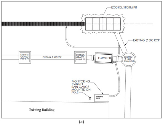
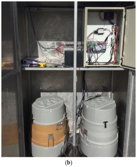
Figure 3.
Installed instrumentation: (a) Instrumentation layout [8]; (b) Influent and effluent autosamplers and data loggers.
Sampling locations for the stormwater were taken at as close proximity as possible to the device inlet and outlet to avoid potential sources of contamination that would alter the device efficiency data, as recommended by [6]. Figure 4 shows the sample locations.
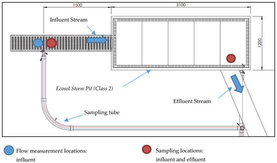
Figure 4.
Flow sensors and sample intake locations [8].
At the start of a rainfall event, a maximum of four grab samples were taken by the influent and effluent autosamplers at 2-min intervals to test for hydrocarbons. Following this, the autosamplers sampled the first eight aliquots at volumetric intervals of up to 1500 L. Following this, the volumetric sampling interval changed to a maximum of 3000 L. The influent and effluent samples (except grab samples) were then composited off-site, independently, using a volume weighted technique for evaluating the Even Mean Concentrations (EMCs) of TSS, TP, TN, and heavy metals.
2.3. Overview of Metrics
2.3.1. Concentration Removal Efficiency (CRE)
Concentration removal efficiency (CRE) is computed to determine the reduction in pollutant concentration through device. The formula for computing CRE for each event is as follows
where and are the event mean concentrations in the inflow and outflow, which were collected as flow-weighted composite samples during each event, as discussed in Section 2.2.
2.3.2. Efficiency Ratio (ER)
The efficiency ratio (ER) is defined in terms of the average event mean concentration (EMC) of pollutants, as shown below
The average EMC is defined based on the arithmetic average as shown below
This method weights EMCs from all storms equally regardless of the relative magnitude of a storm. For example, a high-concentration/high-volume event has a weighting in the average EMC equal to a low concentration/low volume event. This method also minimizes the potential impact of smaller/cleaner runoff from storm events on actual performance calculations. In other words, in a storm-by-storm efficiency approach, a low removal value for such an event is weighted equally to a larger value [14].
2.3.3. Summation of Loads (SOL)
The summation of the loads (SOL) method defines the efficiency based on the ratio of the summation of all influent loads to the summation of all effluent loads, as shown below
The sum of inlet and outlet loads are calculated as
In Equation (5), is the total volume of flow for storm event j, and m is number of qualifying events.
2.3.4. Efficiency of Individual Storm Loads (ISL)
The Efficiency of Individual Storm Loads (ISL) method calculates efficiency for each storm event based on the loads in versus the loads out. The mean value of these individual efficiencies can be taken as the overall efficiency of the device. The efficiency of the device for a single storm is given by the Environmental Protection Agency (EPA) [14], as shown below
The average efficiency for all qualifying events is calculated as below
It can be seen that for average efficiency, the weight of all storms is equal, and efficiency is viewed as an average performance value, regardless of storm size.
2.3.5. Regression of Loads (ROL)
The regression of loads (ROL) method, as described by Martin and Smoot [15], defines the regression efficiency as the slope () of the least-squares linear regression of inlet loads and outlet loads of pollutants, with the intercept constrained to zero. The zero intercept is specified as an “engineering approximation that allows the calculation of an overall efficiency and meets the general physical condition of zero loads-in (zero rainfall) yield zero loads-out”. The equation for the ROL efficiency is defined as below
The regression method determines the line about which the sum of the squares of the deviations of loads-out are at a minimum subject to the constraint of an origin intercept. For storms with small loads, the deviations are small, though the individual storm efficiency may be relatively high. This method gives equal weight to the deviations from the regression line, but not to individual storm efficiencies. Therefore, more influence is given to large storms in the regression method than in the averaging method [15]. In this method, squared correlation (R2) and root mean square error (RMSE) is suggested as a measure of the consistency of the regression because it is not affected by the spurious correlation that occurs when regressing loads data. Regression of loads data produce spurious correlations because the same discharge is incorporated into the independent and dependent regression variables [16].
Since a nonlinear regression is often more suitable for much influent and effluent data, Equation (8) needs to be corrected when the fitting curve is not a straight line. In the case of nonlinear regression, the fitting curve does not have a constant slope, and Equation (8) is no longer valid. In this paper, a new formula for calculating the percentage removal in the case of a nonlinear regression is presented.
If is the nonlinear function of a fitting curve (x is the input loading and y is the output loading), then the percentage of the mass of the influent load that is not collected by the unit (i.e. transported through to the effluent load) is defined based on the area under the fitting curve divided by the area under the line with a unitary slope. That is, this unitary slop line corresponds to the null filter, where the input load is equal to the output load, as shown in Figure 5. Then, the percentage removal is given conceptually as
which is given mathematically as
where is the area under the fitting curve between the limits of 0 and x; and is the area under the line for the null filter (input = output) between these limits, as shown in Figure 5.
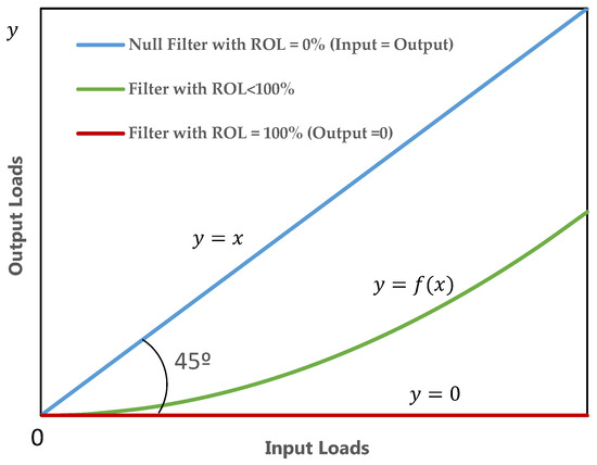
Figure 5.
Regression of Loads for Filters with ROL = 0 to 100%.
For the evaluation of the regression curve, both the squared correlation () and the root mean squared error (RMSE) are calculated, as shown below
where and are the measured and predicted output loading, respectively, and is the average of the measured output loading.
2.3.6. Regression of Concentrations (ROC)
Equations (9)–(12) could also be used for the EMCs’ input and output values. In this case, ROL is called Regression of Concentrations (ROC). To calculate ROC from Equation (10), x and y are the EMC influent and EMC effluent, respectively, and in Equations (11) and (12), and are the measured and predicted EMC effluent, and is the average of the measured EMC effluent.
2.3.7. Confidence Level
According to SQIDEP [6], pollutants with relatively consistent concentrations and removal rates may require only a smaller number of events to be analyzed to achieve statistical confidence for performance characterization. Where pollutant concentrations and removal rates are more variable, additional samples may be required to account for this variability. If the level of statistical significance is not achievable, more events must be sampled until 90% statistical significance is achieved.
3. Results and Discussion
In accordance with SQIDEP [6], the two key criteria for accepting a rainfall event as a qualifying event are based on: (1) the run-off hydraulic properties; and (2) the pollutant concentration values. In the case of the hydraulic criteria, at least two peak inflows from sampled events should exceed 75% of the design TFR of the device (14.0 L/s in this case), and one at or greater than the design TFR. It is also required that 80% of events should have a minimum of eight aliquots. A nominal minimum antecedent dry period (ADP) of six hours of no rain is recommended by [6] to allow for sufficient recharging of pollutants between events and allow time to reset the samplers. If 6 h is not achieved, the inlet pollutant concentration is to be assessed to ensure the concentration is not too low.
For the pollutant criteria, the mean concentration of any individual event should fall within two standard deviations of the typical untreated stormwater contaminant concentrations, as presented in Table 1 of [6]. Any mean concentrations above these values are to be automatically disqualified from the analysis. The averaged EMC of all qualifying storms should fall within one standard deviation of the expected catchment mean concentration. Storms with influent pollutant concentrations below the recommended minimum in Table 1 of [6] (the limit of detection (LOD)) were also excluded.
A total number of 37 rainfall events were recorded from May 2017 to July 2019. Details of each event during the field tests have been recorded and are shown in Table A1 in Appendix A. The events were observed to cover a wide range of antecedent conditions, storm behaviors, and consequent flow rates, with antecedent dry periods from 1.23 to over 3000 h, rain depths ranging from 6.0 to 36.0 mm, and peak flow rates through the unit ranging from 1.75 to 23.0 L/s. A total of 34 events passed the hydraulic criteria. Finally, based on [6], the total number of qualifying events for each pollutant type is as follows: 15 for TSS; 20 for TP; 15 for TN; 21 for THM; 15 for TPH; 15 for TRH. For all qualifying events as identified by the sampling methodology, the event mean concentrations (EMCs) were determined from a local, independent NATA accredited laboratory analysis of a flow-weighted composite of several samples collected during the qualifying storm, as described in Section 2. The results of the EMCs for both the influent and effluent streams for these pollutants are shown in Table 2 and Table A2, Table A3, Table A4, Table A5 and Table A6. An effluent pollutant concentration less than the limit of detection was set as half of the LOD, as suggested by [6]. The EMC results for TSS were based on a rescaling of the data as determined from a statistical analysis of autosampler data compared to manually sampled data, as outlined in the technical field test report [17]. As is widely understood in the literature, autosamplers may underestimate the TSS concentration due to solid segregation effects, imperfect sampling or homogenization procedures [18] and line transport velocity. Manually controlled sampling is a more accurate sampling procedure and can be used to determine inaccuracies associated with autosamplers. For evaluating the difference in the TSS concentrations from the autosampler and the manual grab samples, two sets of samples for TSS were collected for four individual events: one set was obtained by grab samples from over the v notch weir and at the outlet pipe, the other was taken by the autosamplers at the same time from both the influent and effluent streams. It was observed that there were significant differences in the two methods of sampling for TSS at the inlet, and that this difference needed to be considered and taken into account when analyzing the data for TSS. As discussed, this difference is attributed to the errors associated with autosamplers, the manual grab sample is considered to be of higher accuracy.

Table 2.
Total suspended solids (TSS) influent and effluent results (LOD = 5 mg/L).
3.1. Statistical Analysis
To evaluate the filtration performance of the device, a statistical characterization and analysis of the EMC data is required. The results of normal and lognormal distribution tests for the influent and effluent EMC datasets based on the Shapiro–Wilk and Anderson–Darling tests are shown in Table 3 and Table A8. As is clear from Table 3, the EMC of all pollutants (except TSS) is evaluated as being likely to be lognormally distributed, and for TSS it is evaluated to be more likely to be normally distributed. The results of the distribution tests are used to assess the difference between the distributions of the influent and effluent samples, as well as estimating the summary statistics of the datasets.

Table 3.
Normal and Lognormal distribution test for even mean concentration (EMC) influent and effluent.
For log-normal data, estimates of the arithmetic summary statistics of the population (mean, median, standard deviation, and coefficient of variation) should be based on their theoretical relationships with the mean and standard deviation of the transformed data. Computing the mean and standard deviation of log transforms of the sample EMC data and then converting them to an arithmetic estimate often obtains a better estimate of the mean of the population due to the more typical distributional characteristics of water quality data. This value will not necessarily match that produced by the simple arithmetic average of the data for smaller datasets. Both provide an estimate of the population mean, but the approach utilizing the log-transformed data tends to provide a better estimator [14]. Gilbert [19] recommends that in cases where the data are not highly skewed (coefficient of variation (COV) less than 1.2), that the arithmetic mean is the preferred measure of central tendency. The arithmetic summary statistics of the datasets along with COV are presented in Table 4, and it is evident that all the data have a COV of much less than 1.2 (even less than 1.0). Consequently, the arithmetic summary statistics of the influent and effluent population (mean, median, standard deviation, and COV) are used to calculate the performance of the device.

Table 4.
Arithmetic summary statistics of the data sets.
Figure 6 presents the cumulative probability plot for both influent and effluent concentrations for all paired data. Probability plots are among the most useful pieces of information that can result from a device evaluation study [13], because they provide both an indication of the normality of the distribution of the data, and also a visual comparison of the influent and effluent distributions. Note that for TSS, TPH, and TRH the distributions are very distinct, which indicates that a substantial reduction in TSS, TPH, and TRH does occur from the influent to the effluent stream.
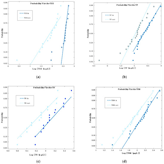
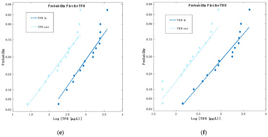
Figure 6.
Probability plots for pollutants: (a) TSS; (b) total phosphorous (TP); (c) total nitrogen (TN); (d) total heavy metals (THM); (e) total petroleum hydrocarbons (TPH); (f) total recoverable hydrocarbons (TRH).
3.1.1. Box and Whisker Plots
Box and whisker plots provide a schematic representation of the central tendency and spread of the influent and effluent EMC datasets. The box plots summarize the 25th and 75th percentiles, the median, and outlying observations. Notched box and whisker plots for TSS, TP, TN, THM, TPH, and TRH are shown in Figure 7, where the notches indicate the 95% confidence interval about the median. It can be seen that the lower confidence limit on the median for influent TN and effluent TRH is less than the lower quartile, resulting in the reversal of the lines at the bottom of the box plot. Overlapping confidence intervals in influent and effluent box plots are an indication that the central tendency of the data (i.e., the mean or median) may not be significantly different. From the six box plots, it is to be expected that TSS, THM, TPH, and TRH medians are significantly different, whereas this is not immediately clear for TP and TN medians. This will be discussed in the next section.
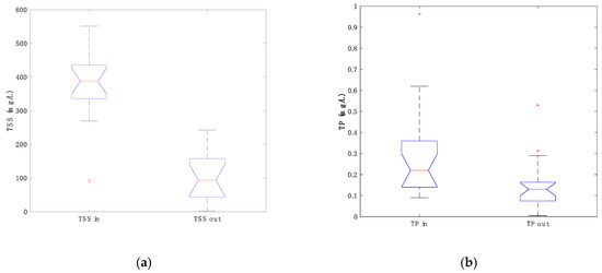
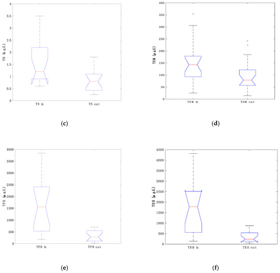
Figure 7.
Box and Whisker plots for the pollutant: (a) TSS; (b) TP; (c) TN; (d) THM; (e) TPH; (f) TRH.
Interleaved bar graphs of influent and effluent for all pollutants are also shown in Figure 8, which provide a direct comparison of the relative magnitude of the concentrations from the influent versus the effluent streams.
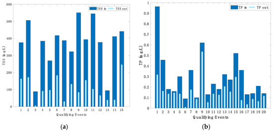
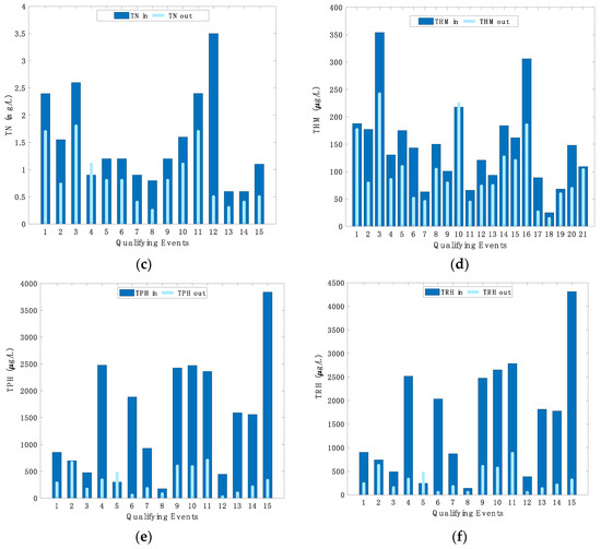
Figure 8.
Interleaved bar plots for all pollutants: (a) TSS; (b) TP; (c) TN; (d) THM; (e) TPH; (f) TRH.
3.1.2. Statistical Comparison of Event Mean Concentrations
Within the following section, the performance efficacy of the device is analyzed; prior to this analysis, it is necessary to undertake a statistical analysis of the device’s influent and effluent concentrations to determine the presence of statistically significant differences, and hence a statistically significant filtration [14]. Statistical significance testing of the difference between the influent and effluent EMCs was undertaken based on the normal and lognormal distribution assumptions of the EMC data, as discussed in Section 3.1. The significance tests determine whether the difference between the central tendency of the concentrations for the influent and effluent EMCs is statistically significant. The selection of the appropriate statistical significance test depends on the distribution and size of the datasets, as presented in Section 3.1. The statistical significance tests adopted are (1) Sign Test; (2) Wilcoxon–Mann–Whitney Rank test; and (3) the paired t-test. Nonparametric tests (Tests 1 or 2) are only needed if the data are not normally distributed (even after log transformation). As the data are normal or lognormal, the validity of the paired t-test (Test 3) holds; however, for the purpose of completion, all tests are used for the purpose of comparison.
The tests are performed by comparing the difference between the influent and effluent datasets over all qualifying events. The results are shown in Table 5. From the results of the statistical significance testing, it may be seen that the critical value for the rejection of equality of means (the p-value) for all pollutants is well below the predetermined significance value of α = 0.05. Hence, the influent and effluent EMCs for all pollutants are significantly different in their means, meaning that the Storm Pit (Class 2) is found to operate effectively for all pollutant types.

Table 5.
Parametric test results—Paired Samples t-test.
The same results were also achieved for the non-parametric test, and it was observed that differences between influent and effluent for EMC for all pollutants are significantly different in their medians, even though removal was not immediately clear, from consideration of the boxplots for TP and TN.
3.2. Evaluation of Performance Metrics
Performance metrics for the Ecosol Storm Pit (Class 2) for filtration of each pollutant type, based on the EMC results, are presented in this section. A variety of pollutant removal calculation methods have been utilized in monitoring studies to evaluate the efficacy of the performance of the device. The methods considered to characterize removal efficiencies are: Concentration Removal Efficiency (CRE); Efficiency Ratio (ER); Summation of Loads (SOL); Average Efficiency; Regression of Loads (ROL); and Regression of Concentration (ROC).
3.2.1. Efficiency Metrics
Statistics (e.g., mean, median, standard deviation and COV) for the efficiency performance metrics and confidence level across the range of qualifying storm events for all pollutants are shown in Table 6.

Table 6.
Statistics for efficiency performance metrics.
3.2.2. Regression Metrics
Figure 9 shows the best regression fitting curves for all pollutant loads. It can be seen that for all pollutants (except TSS and THM), the fitting curves are not linear. The values of , , and ROL are shown in Table 7. Note that ROL efficiencies for all pollutant loads were calculated based on Equation (10) at , where is the centroid of the area under the fitting curve.
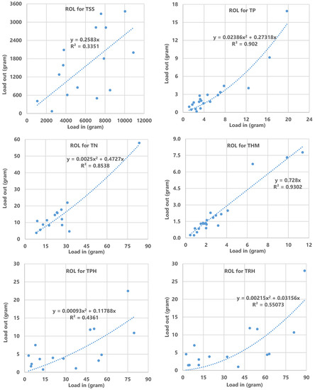
Figure 9.
Regression fitting curves for pollutant loads (ROL).

Table 7.
Regression of load results.
Figure 10 shows the best regression fitting curves for all EMC pollutants. Note that the fitting curves for TSS, TPH, and TRH are linear, while for TP, TN, and THM they are not linear. The ROC for all pollutants along with regression curve fitting details are also shown in Table 8. ROC efficiencies for all EMCs pollutant were calculated based on Equation (10) at , where is the centroid of the area under the fitting curve.
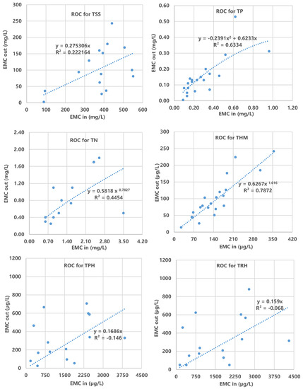
Figure 10.
Regression fitting curves for pollutant concentrations (ROC).

Table 8.
Regression of concentration results.
3.2.3. Concentration Removal Efficiency versus Event Mean Concentration
Figure 11 shows graphs of the concentration removal efficiency as a function of the influent concentration for all pollutant types. It is observed that only in cases of TPH and TRH is there a mild trend that indicates increasing efficiencies with increasing influent concentration. However, in other pollutants there is no coherent relationship between these two parameters.
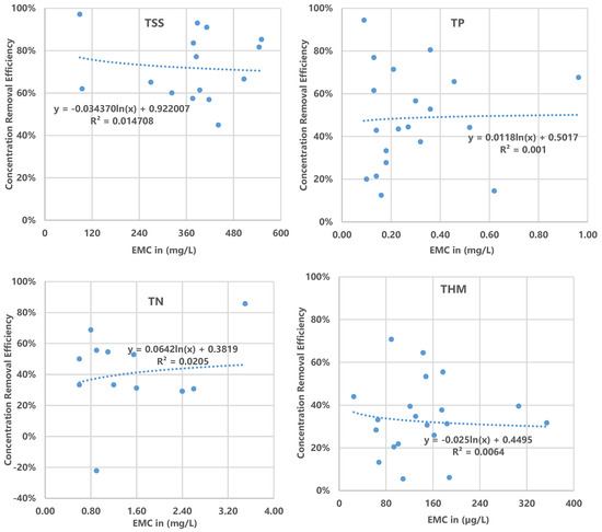
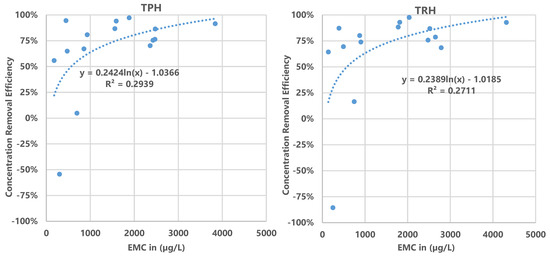
Figure 11.
Concentration Removal Efficiency as a function of influent concentration for all pollutants.
3.2.4. Summary of Removal Efficiency
Efficiency results, along with confidence levels for all pollutants, are shown in Table 9 and Figure 12. As discussed before, ER and ROC are related to EMCs, whereas SOL and ROL are related to the total pollutant loads. It can be seen that there is good agreement between the results of efficiencies for each pollutant, with variations amongst metrics being within 5% of one another.

Table 9.
Efficiency results for Ecosol Storm Pit (Class 2).
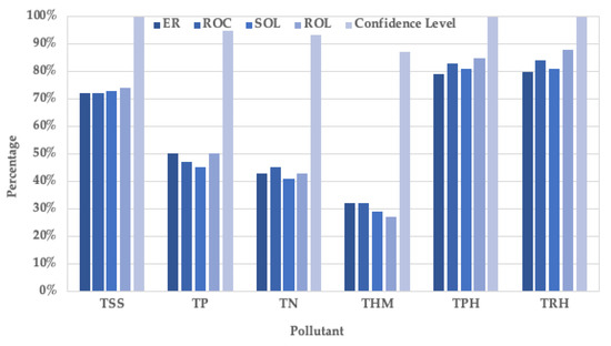
Figure 12.
Efficiency Results for Ecosol Storm Pit (Class 2).
It is noted that the required SQIDEP [6] confidence level of 90% was achieved for pollutants TSS, TP, TN, TPH, and TRH, while for THM, confidence level was marginally lower at 87.3%.
3.3. Discussion
For the purposes of discussion, the results for the Ecosol Storm Pit (Class 2) are compared to a similar field study. The field results for a system comprised of a similar treatment train involving 200 micron mesh pit baskets followed by media cartridge filters (perlite, zeolite and activated alumina) were reported in [20]. The site was also located in Queensland, Australia, but the catchment possessed only residential land-use, and was predominantly roof area (56%). Based on an analysis of nine qualifying events, the reported efficiency ratios were 32% for TSS, 37% for TP and 38% for TN for the pit basket, and 87% for TSS, 55% for TP and 42% for TN for the cartridge filter. These reported removal efficiencies for the cartridge filter from [20] are within one standard deviation of the TSS results and half a standard deviation of the TP and TN results for the Ecosol Storm Pit (Class 2). However, a direct comparison between the approaches is difficult, not only because of the limited number of events in [20], but particularly given that the pollutant concentration levels were significantly less than the concentration levels from the field tests within this study. For example, the median (mean) influent EMC from for TSS from [20] was less than 10% [27%] of that experienced in the field tests reported here, and the influent ECM for the cartridge was less than 4% [7%]. Despite these differences, the efficacy of the combined treatment of a filtration mesh followed by a media filter is evident.
In highly controlled laboratory experiments, [21] studied the effectiveness of an up-flow filtration system using a novel polypropylene fibrous media. This new media is highly porous, and forms a floating filtration layer. Removal rates for suspended solids varied from 70% within the pre-treatment chamber up to 94% within the media chamber, highlighting what is achievable under highly controlled conditions. However, concentration levels within [21] were less than half those encountered within this study. In consideration of TN and TP, it is important to note that high removal efficiencies are achievable within retention-based systems, for example the bio-retention work from [22]. However, these systems are typically a secondary treatment option, as opposed to the Ecosol Storm Pit (Class 2), which is intended as an at-source treatment.
4. Conclusions
With support in the industry growing for more certainty around performance claims for stormwater filtration devices and methods, Stormwater Australia and key industry stakeholders, in consultation with practitioners, developed the “Stormwater Quality Improvement Device Evaluation Protocol” (SQIDEP) [6] for testing a water-sensitive urban design asset’s pollutant removal characteristics. SQIDEP [6] encourages consistent, scientifically rigorous and independent field testing to validate device performance. This paper details the field test performance results for the Ecosol Storm Pit (Class 2), in accordance with this protocol. All event sampling was independently completed by Moreton Environmental and the data independently analyzed by The University of Adelaide.
The analysis demonstrated the difference in event mean concentrations for the influent and effluent streams to be statistically significant for the range of metrics considered, where the removal efficiencies of the Ecosol Storm Pit (Class 2) are summarized as: between 72 and 74% for TSS with the influent EMC range from 0.0 to 551 mg/L and load range from 0.0 to 10,900 g; 45–50% for TP with the influent EMC range from 0.0 to 0.96 mg/L and load range from 0.0 to 20 g; 41–45% for TN with the influent EMC range from 0.0 to 3.50 mg/L and load range from 0.0 to 84 g; 27–32% for THM with the influent EMC range from 0.0 to 0.35 mg/L and load range from 0.0 to 11.4 g; 79–85% for TPH with the influent EMC range from 0.0 to 3.84 mg/L and load range from 0.0 to 80 g; and 80–88% for TRH with the influent EMC range from 0.0 to 4.30 mg/L and load range from 0.0 to 89 g.
This work represents the culmination of an extensive two-year field study, where a full-scale unit was subject to a wide variety of storm events and consequent operating conditions. The SQIDEP framework [6] provided a rigorous guide for the development and analysis of the field study. Given the inherent variability in the field results, it was important to undertake extensive testing to provide a statistically meaningful characterization of the removal efficiencies. A key learning from this project is the importance of judicious selection of storm events for chemical analysis of the samples (i.e., ensuring adherence of the event to the qualifying criteria as discussed in Section 3), as this represents a significant component of the overall project costs. Despite the difficulties, well-designed full-scale field studies provide the most rigorous testing regime for storm water filtration studies.
Author Contributions
The authors have contributed equally to the preparation of this article. All authors have read and agreed to the published version of the manuscript.
Funding
This research was funded by Urban Asset Solutions Pty Ltd through direct funding to The University of Adelaide.
Acknowledgments
The authors acknowledge the funding of this project by Urban Asset Solutions Pty Ltd., in particular Andrew Macklin; Adrian Fair; and Sam Kowald for their generous support.
Conflicts of Interest
The authors declare no conflict of interest.
Appendix A. Event Data

Table A1.
Details of all Events during the field testing.
Table A1.
Details of all Events during the field testing.
| Events | Date/Time | Antecedent Dry Period (ADP) (h) | Rain Depth (mm) | Number of Aliquots | Maximum Intensity (mm/h) | Peak Flow Rate (L/s) | Percentage of Design Flow | Qualifying Events? (Based on Hydraulic Criteria) (Y/N) | |||
|---|---|---|---|---|---|---|---|---|---|---|---|
| Start | End | Duration (h) | |||||||||
| Influent | Effluent | ||||||||||
| Rainfall 1 | 18/5/17 23:06 | 19/5/17 23:58 | 24.87 | 75.00 | 9.8 | 9 | 12 | 4.1 | 4.1 | 29.1% | Y |
| Rainfall 2 | 10/6/17 19:46 | 11/6/17 16:56 | 21.17 | 523.80 | 15.6 | 10 | 30 | 2.5 | 2.5 | 17.9% | Y |
| Rainfall 3 | 15/7/17 18:28 | 15/7/17 21:00 | 2.53 | 817.53 | 26.0 | 7 | 102 | 8.0 | 8.0 | 57.1% | Y |
| Rainfall 4 | 18/11/17 11:00 | 19/11/17 20:00 | 33.00 | 3014.00 | 31.6 | 20 | 84 | 14.7 | 14.7 | 104.7% | Y |
| Rainfall 5 | 20/11/17 23:00 | 21/11/17 9:00 | 10.00 | 27.00 | 11.4 | 14 | 90 | 11.1 | 11.1 | 79.1% | Y |
| Rainfall 6 | 29/11/17 5:00 | 30/11/17 18:00 | 37.00 | 188.00 | 19.4 | 10 | 31 | 4.8 | 4.8 | 34.4% | Y |
| Rainfall 7 | 4/12/17 12:00 | 4/12/17 18:00 | 6.00 | 90.00 | 21.8 | 13 | 24 | 5.5 | 5.5 | 39.6% | Y |
| Rainfall 8 | 25/12/17 19:00 | 25/12/17 20:20 | 1.33 | 505.00 | 34.6 | 20 | 90 | 12.8 | 12.8 | 91.7% | Y |
| Rainfall 9 | 2/1/18 19:00 | 2/1/18 22:00 | 3.00 | 191.00 | 16.8 | 18 | 48 | 10.2 | 10.2 | 73.0% | Y |
| Rainfall 10 | 1/2/18 18:12 | 4/2/18 14:02 | 67.83 | 716.20 | 31.0 | 10 | 36 | 4.1 | 4.1 | 28.9% | Y |
| Rainfall 11 | 11/2/18 18:00 | 11/2/18 23:58 | 5.97 | 171.97 | 36.4 | 11 | 150 | 22.2 | 22.2 | 158.6% | Y |
| Rainfall 12 | 22/2/18 15:50 | 23/2/18 0:52 | 9.03 | 255.87 | 21.6 | 20 | 36 | 14.3 | 14.3 | 102.1% | Y |
| Rainfall 13 | 26/2/18 19:46 | 26/2/18 21:46 | 2.00 | 90.90 | 32.2 | 15 | 90 | 18.5 | 18.5 | 132.1% | Y |
| Rainfall 14 | 6/3/18 0:32 | 6/3/18 4:20 | 3.80 | 170.77 | 17.8 | 10 | 54 | 7.3 | 7.3 | 52.2% | Y |
| Rainfall 15 | 21/3/18 0:50 | 22/3/18 3:20 | 26.50 | 356.50 | 14.0 | 10 | 48 | 11.4 | 11.4 | 81.4% | Y |
| Rainfall 16 | 22/3/18 20:00 | Sampler Failed | N | ||||||||
| Rainfall 17 | 26/8/18 9:36 | Sampling Methodology Failed | N | ||||||||
| Rainfall 18 | 4/9/18 13:18 | 4/9/18 16:18 | 3.00 | 217.3 | 21.8 | 24 | 72 | 18.34 | 18.34 | 40.3% | Y |
| Rainfall 19 | 11/10/18 12:56 | 11/10/18 13:48 | 0.87 | 884.63 | 8.0 | 9 | 24 | 5.64 | 5.64 | 35% | Y |
| Rainfall 20 | 12/10/18 23:10 | 13/10/18 6:20 | 7.17 | 33.37 | 11.0 | 10 | 30 | 4.84 | 4.84 | 22% | Y |
| Rainfall 21 | 13/10/18 9:54 | 13/10/18 19:20 | 9.43 | 3.57 | 15.8 | 14 | 30 | 3.11 | 3.11 | 29.1% | Y |
| Rainfall 22 | 21/10/18 14:30 | Sampler Failed to Trigger | N | ||||||||
| Rainfall 23 | 5/12/18 11:14 | 5/12/18 13:45 | 2.52 | NA | 12.8 | 24 | 7 | 7 | 12.8 | 50.0% | Y |
| Rainfall 24 | 16/12/18 16:30 | 16/12/18 21:40 | 5.17 | 266.75 | 22.6 | 22 | 9.3 | 9.3 | 22.6 | 66.4% | Y |
| Rainfall 25 | 3/1/19 21:58 | 3/1/19 23:58 | 2.00 | 432.3 | 7.0 | 8 | 7.3 | 7.3 | 7 | 52.1% | Y |
| Rainfall 26 | 4/2/19 6:50 | 4/2/19 9:40 | 2.83 | 750.87 | 8.0 | 7 | 5.55 | 5.55 | 8 | 39.6% | Y |
| Rainfall 27 | 5/2/19 22:10 | 6/2/19 3:00 | 4.83 | 36.5 | 22.4 | 24 | 16.2 | 16.2 | 22.4 | 115.7% | Y |
| Rainfall 28 | 7/2/19 2:30 | 7/2/19 4:52 | 2.37 | 23.5 | 9.0 | 11 | 7.46 | 7.46 | 9 | 53.3% | Y |
| Rainfall 29 | 27/3/19 8:50 | 27/3/19 17:50 | 9.00 | 1155.97 | 21.4 | 21 | 36 | 10.32 | 10.32 | 73.7% | Y |
| Rainfall 30 | 2/4/19 17:00 | 2/4/19 20:50 | 3.83 | NA | 19.6 | 19 | 48 | 12.3 | 12.3 | 87.9% | Y |
| Rainfall 31 | 20/4/19 9:36 | 20/4/19 12:36 | 3.00 | 420.8 | 6 | 8 | 72 | 13.12 | 13.12 | 93.7% | Y |
| Rainfall 32 | 20/4/19 15:36 | 20/4/19 19:00 | 3.40 | 3 | 13.4 | 16 | 84 | 10 | 10 | 71.4% | Y |
| Rainfall 33 | 17/5/19 0:00 | 17/5/19 10:10 | 10.17 | 629 | 12 | 7 | 18 | 1.75 | 1.75 | 12.5% | Y |
| Rainfall 34 | 16/06/2019 16:10 | 16/06/2019 17:35 | 1.42 | 726 | 22.8 | 12 | 240 | 23.05 | 23.05 | 164.3% | Y |
| Rainfall 35 | 24/6/19 22:00 | 25/6/19 18:32 | 20.53 | 196.42 | 11.0 | 10 | 24 | 8.2 | 8.2 | 58.6% | Y |
| Rainfall 36 | 25/6/19 19:46 | 26/6/19 5:42 | 9.93 | 1.23 | 21.2 | 13 | 30 | 11.9 | 11.9 | 85.0% | Y |
| Rainfall 37 | 4/7/19 23:34 | 5/7/19 0:34 | 1.00 | 209.87 | 8.2 | 20 | 24 | 4.61 | 4.61 | 32.9% | Y |

Table A2.
TP influent and effluent results (LOD = 0.01 mg/L).
Table A2.
TP influent and effluent results (LOD = 0.01 mg/L).
| Qualifying Event No | Rainfall No | Number of Aliquots | Max Flowrate (L/s) | Flow Volume (L) | TP (mg/L) | |
|---|---|---|---|---|---|---|
| Influent | Effluent | |||||
| 1 | Rainfall 1 | 9 | 4.1 | 12,933 | 0.963 | 0.312 |
| 2 | Rainfall 2 | 10 | 2.5 | 11,305 | 0.457 | 0.157 |
| 3 | Rainfall 5 | 14 | 11.1 | 9903 | 0.180 | 0.130 |
| 4 | Rainfall 6 | 10 | 4.8 | 19,838 | 0.160 | 0.140 |
| 5 | Rainfall 7 | 13 | 5.5 | 22,158 | 0.300 | 0.130 |
| 6 | Rainfall 8 | 20 | 12.8 | 28,867 | 0.090 | 0.005 |
| 7 | Rainfall 9 | 18 | 10.2 | 19,693 | 0.360 | 0.170 |
| 8 | Rainfall 10 | 10 | 4.1 | 20,485 | 0.100 | 0.080 |
| 9 | Rainfall 11 | 11 | 22.2 | 31,853 | 0.620 | 0.530 |
| 10 | Rainfall 12 | 20 | 14.3 | 30,000 | 0.130 | 0.050 |
| 11 | Rainfall 13 | 15 | 18.5 | 33,889 | 0.230 | 0.130 |
| 12 | Rainfall 14 | 10 | 7.3 | 18,181 | 0.180 | 0.120 |
| 13 | Rainfall 15 | 10 | 11.4 | 14,600 | 0.320 | 0.200 |
| 14 | Rainfall 18 | 24 | 18.34 | 60,959 | 0.270 | 0.150 |
| 15 | Rainfall 19 | 9 | 5.64 | 6671 | 0.520 | 0.290 |
| 16 | Rainfall 20 | 10 | 4.84 | 9266 | 0.360 | 0.070 |
| 17 | Rainfall 21 | 14 | 3.11 | 18,476 | 0.130 | 0.030 |
| 18 | Rainfall 24 | 22 | 9.3 | 21,890 | 0.140 | 0.080 |
| 19 | Rainfall 25 | 8 | 7.3 | 7515 | 0.210 | 0.060 |
| 20 | Rainfall 26 | 7 | 5.55 | 8400 | 0.140 | 0.110 |

Table A3.
TN influent and effluent results (LOD = 0.1 mg/L).
Table A3.
TN influent and effluent results (LOD = 0.1 mg/L).
| Qualifying Event No | Rainfall No | Number of Aliquots | Max Flowrate (L/s) | Flow Volume (L) | TN (mg/L) | |
|---|---|---|---|---|---|---|
| Influent | Effluent | |||||
| 1 | Rainfall 1 | 9 | 4.1 | 12,933 | 2.397 | 1.697 |
| 2 | Rainfall 2 | 10 | 2.5 | 11,305 | 1.551 | 0.732 |
| 3 | Rainfall 4 | 20 | 14.7 | 32,159 | 2.600 | 1.800 |
| 4 | Rainfall 5 | 14 | 11.1 | 9903 | 0.900 | 1.100 |
| 5 | Rainfall 7 | 13 | 5.5 | 22,158 | 1.200 | 0.800 |
| 6 | Rainfall 9 | 18 | 10.2 | 19,693 | 1.200 | 0.800 |
| 7 | Rainfall 12 | 20 | 14.3 | 30,000 | 0.900 | 0.400 |
| 8 | Rainfall 13 | 15 | 18.5 | 33,889 | 0.800 | 0.250 a |
| 9 | Rainfall 14 | 10 | 7.3 | 18,181 | 1.200 | 0.800 |
| 10 | Rainfall 15 | 10 | 11.4 | 14,600 | 1.600 | 1.100 |
| 11 | Rainfall 19 | 9 | 5.64 | 6671 | 2.400 | 1.700 |
| 12 | Rainfall 20 | 10 | 4.84 | 9266 | 3.500 | 0.500 |
| 13 | Rainfall 21 | 14 | 3.11 | 18,476 | 0.600 | 0.300 |
| 14 | Rainfall 24 | 22 | 9.3 | 21,890 | 0.600 | 0.400 |
| 15 | Rainfall 25 | 8 | 7.3 | 7515 | 1.100 | 0.500 |
a For this event LOD was reported as 0.5 mg/L by the laboratory analysis.

Table A4.
THM influent and effluent results (LOD not available).
Table A4.
THM influent and effluent results (LOD not available).
| Qualifying Event No | Rainfall No | Number of Aliquots | Max Flowrate (L/s) | Flow Volume (L) | THM (µg/L) | |
|---|---|---|---|---|---|---|
| Influent | Effluent | |||||
| 1 | Rainfall 1 | 9 | 4.1 | 12,933 | 187.9 | 176.4 |
| 2 | Rainfall 2 | 10 | 2.5 | 11,305 | 177.1 | 78.82 |
| 3 | Rainfall 4 | 20 | 14.7 | 32,159 | 354.0 | 241.8 |
| 4 | Rainfall 5 | 14 | 11.1 | 9903 | 130.5 | 85.16 |
| 5 | Rainfall 6 | 10 | 4.8 | 19,838 | 175.1 | 109.0 |
| 6 | Rainfall 7 | 13 | 5.5 | 22,158 | 143.2 | 50.90 |
| 7 | Rainfall 8 | 20 | 12.8 | 28,867 | 63.11 | 45.20 |
| 8 | Rainfall 9 | 18 | 10.2 | 19,693 | 150.0 | 104.0 |
| 9 | Rainfall 10 | 10 | 4.1 | 20,485 | 101.0 | 78.91 |
| 10 | Rainfall 11 | 11 | 22.2 | 30,000 | 217.9 | 223.9 |
| 11 | Rainfall 12 | 20 | 14.3 | 30,000 | 65.93 | 44.05 |
| 12 | Rainfall 13 | 15 | 18.5 | 33,889 | 121.0 | 73.25 |
| 13 | Rainfall 14 | 10 | 7.3 | 18,181 | 93.48 | 74.34 |
| 14 | Rainfall 15 | 10 | 11.4 | 14,600 | 184.0 | 126.5 |
| 15 | Rainfall 18 | 24 | 18.34 | 60,959 | 162.0 | 120.0 |
| 16 | Rainfall 19 | 9 | 5.64 | 6671 | 306.1 | 185.1 |
| 17 | Rainfall 20 | 10 | 4.84 | 9266 | 89.10 | 26.05 |
| 18 | Rainfall 21 | 14 | 3.11 | 18,476 | 25.00 | 14.00 |
| 19 | Rainfall 24 | 22 | 9.3 | 21,890 | 68.00 | 59.00 |
| 20 | Rainfall 25 | 8 | 7.3 | 7515 | 148.0 | 69.00 |
| 21 | Rainfall 26 | 7 | 5.55 | 8400 | 109.0 | 103.0 |

Table A5.
TPH influent and effluent results (LOD = 50 µg/L).
Table A5.
TPH influent and effluent results (LOD = 50 µg/L).
| Qualifying Event No | Rainfall No | Max Flowrate (L/s) | Flow Volume (L) | TPH (µg/L) | |
|---|---|---|---|---|---|
| Influent | Effluent | ||||
| 1 | Rainfall 1 | 4.1 | 12,933 | 855.2 | 281.5 |
| 2 | Rainfall 2 | 2.5 | 11,305 | 697.7 | 665.0 |
| 3 | Rainfall 3 | 8 | 9857 | 476.3 | 167.5 |
| 4 | Rainfall 4 | 14.7 | 32,159 | 2478 | 338.3 |
| 5 | Rainfall 5 | 11.1 | 9903 | 300.7 | 464.3 |
| 6 | Rainfall 6 | 4.8 | 19,838 | 1885 | 54.18 |
| 7 | Rainfall 7 | 5.5 | 22,158 | 930.8 | 179.5 |
| 8 | Rainfall 8 | 12.8 | 28,867 | 178.6 | 79.02 |
| 9 | Rainfall 9 | 10.2 | 19,693 | 2425 | 597.5 |
| 10 | Rainfall 10 | 4.1 | 20,485 | 2471 | 585.7 |
| 11 | Rainfall 11 | 22.2 | 31,853 | 2361 | 705.5 |
| 12 | Rainfall 12 | 14.3 | 30,000 | 448.7 | 25.00 |
| 13 | Rainfall 13 | 18.5 | 33,889 | 1591 | 95.06 |
| 14 | Rainfall 14 | 7.3 | 18,181 | 1560 | 208.4 |
| 15 | Rainfall 15 | 11.4 | 14,600 | 3840 | 330.3 |

Table A6.
TRH influent and effluent results (LOD = 100 µg/L).
Table A6.
TRH influent and effluent results (LOD = 100 µg/L).
| Qualifying Event No | Rainfall No | Max Flowrate (L/s) | Flow Volume (L) | TRH (µg/L) | |
|---|---|---|---|---|---|
| Influent | Effluent | ||||
| 1 | Rainfall 1 | 4.1 | 12,933 | 903.9 | 236.1 |
| 2 | Rainfall 2 | 2.5 | 11,305 | 746.3 | 623.2 |
| 3 | Rainfall 3 | 8 | 9857 | 493.1 | 151.1 |
| 4 | Rainfall 4 | 14.7 | 32,159 | 2518 | 332.1 |
| 5 | Rainfall 5 | 11.1 | 9903 | 247.6 | 459.6 |
| 6 | Rainfall 6 | 4.8 | 19,838 | 2035 | 50.00 |
| 7 | Rainfall 7 | 5.5 | 22,158 | 875.0 | 174.6 |
| 8 | Rainfall 8 | 12.8 | 28,867 | 140.0 | 50.00 |
| 9 | Rainfall 9 | 10.2 | 19,693 | 2478 | 602.5 |
| 10 | Rainfall 10 | 4.1 | 20,485 | 2651 | 566.2 |
| 11 | Rainfall 11 | 22.2 | 31,853 | 2786 | 880.3 |
| 12 | Rainfall 12 | 14.3 | 30,000 | 389.4 | 50.00 |
| 13 | Rainfall 13 | 18.5 | 33,889 | 1814 | 129.7 |
| 14 | Rainfall 14 | 7.3 | 18,181 | 1779 | 209.3 |
| 15 | Rainfall 15 | 11.4 | 14,600 | 4314 | 315.3 |
Appendix B. Modeling and Distribution Analysis

Table A7.
MUSIC Storm flow mean concentrations for South East Queensland (Log10 Values) [12].
Table A7.
MUSIC Storm flow mean concentrations for South East Queensland (Log10 Values) [12].
| Land Use Category | TSS Concentration Log10 (mg/L) | TP Concentration Log10 (mg/L) | TN Concentration Log10 (mg/L) |
|---|---|---|---|
| Urban Residential | |||
| Roads | 2.43 | −0.30 | 0.26 |
| Roofs | 1.30 | −0.89 | 0.26 |
| Other Impervious Areas | 2.18 | −0.47 | 0.26 |
| Other Pervious Areas | 2.18 | −0.47 | 0.26 |
| Industrial | |||
| Roads | 2.43 | −0.30 | 0.25 |
| Roofs | 1.30 | −0.89 | 0.25 |
| Other Impervious Areas | 2.43 | −0.30 | 0.25 |
| Other Pervious Areas | 2.18 | −0.47 | 0.25 |
| Commercial | |||
| Roads | 2.43 | −0.30 | 0.37 |
| Roofs | 1.30 | −0.89 | 0.37 |
| Other Impervious Areas | 2.43 | −0.30 | 0.37 |
| Other Pervious Areas | 2.18 | −0.47 | 0.37 |

Table A8.
Normal and Lognormal distribution test for EMC influent and effluent.
Table A8.
Normal and Lognormal distribution test for EMC influent and effluent.
| Tabular Results | TSS | TP | TN | THM | TPH | TRH | ||||||
|---|---|---|---|---|---|---|---|---|---|---|---|---|
| Influent | Effluent | Influent | Effluent | Influent | Effluent | Influent | Effluent | Influent | Effluent | Influent | Effluent | |
| Test for normal distribution | ||||||||||||
| Shapiro-Wilk test | ||||||||||||
| W | 0.8779 | 0.9674 | 0.8117 | 0.8167 | 0.8733 | 0.8780 | 0.9210 | 0.9077 | 0.9207 | 0.9141 | 0.9218 | 0.9045 |
| p value | 0.0442 | 0.8181 | 0.0013 | 0.0016 | 0.0377 | 0.0443 | 0.0909 | 0.0496 | 0.1973 | 0.1563 | 0.2053 | 0.1117 |
| Passed normality test? | No | Yes | No | No | No | No | Yes | No | Yes | Yes | Yes | Yes |
| p value summary | * | ns | ** | ** | * | * | ns | * | ns | ns | ns | ns |
| Anderson-Darling test | ||||||||||||
| A2* | 0.7604 | 0.2188 | 1.174 | 1.192 | 0.7719 | 0.7024 | 0.5425 | 0.7567 | 0.4564 | 0.4691 | 0.4418 | 0.5218 |
| p value | 0.0370 | 0.8015 | 0.0034 | 0.0031 | 0.0346 | 0.0525 | 0.1439 | 0.0411 | 0.2287 | 0.2119 | 0.2493 | 0.1539 |
| Passed normality test? | No | Yes | No | No | No | Yes | Yes | No | Yes | Yes | Yes | Yes |
| p value summary | * | ns | ** | ** | * | ns | ns | * | ns | ns | ns | ns |
| Test for lognormal distribution | ||||||||||||
| Shapiro-Wilk test | ||||||||||||
| W | 0.7144 | 0.8070 | 0.9685 | 0.8810 | 0.9516 | 0.9474 | 0.9519 | 0.9593 | 0.9340 | 0.9257 | 0.9252 | 0.9199 |
| p value | 0.0004 | 0.0045 | 0.7221 | 0.0184 | 0.5498 | 0.4842 | 0.3692 | 0.5015 | 0.3132 | 0.2352 | 0.2310 | 0.1919 |
| Passed lognormality test? | No | No | Yes | No | Yes | Yes | Yes | Yes | Yes | Yes | Yes | Yes |
| p value summary | *** | ** | ns | * | ns | ns | ns | ns | ns | ns | ns | ns |
| Anderson-Darling test | ||||||||||||
| A2* | 1.810 | 0.9201 | 0.2363 | 0.7861 | 0.3037 | 0.2925 | 0.3541 | 0.2896 | 0.4318 | 0.3837 | 0.4913 | 0.4056 |
| p value | <0.0001 | 0.0142 | 0.7562 | 0.0342 | 0.5289 | 0.5555 | 0.4289 | 0.5787 | 0.2645 | 0.3495 | 0.1854 | 0.3082 |
| Passed lognormality test? | No | No | Yes | No | Yes | Yes | Yes | Yes | Yes | Yes | Yes | Yes |
| p value summary | *** | * | ns | * | ns | ns | ns | ns | ns | ns | ns | ns |
ns—Not significant; * Significant; ** Very significant; *** Extremely significant.
References
- Department of Planning and Local Government (DPLG). Water Sensitive Urban Design Technical Manual for the Greater Adelaide Region; Government of South Australia: Adelaide, Australia, 2010.
- Urban Asset Solutions (UAS). Ecosol™, Storm Pit (Class 2) Technical Specification; UAS: Adelaide, Australia, 2016. [Google Scholar]
- Lee, B.-C.; Matsui, S.; Shimizu, Y.; Matsuda, T.; Tanaka, Y. A new installation for treatment of road runoff: Up-flow filtration by porous polypropylene media. Water Sci. Technol. 2005, 52, 225–232. [Google Scholar] [CrossRef] [PubMed]
- Athanasiadis, K.; Helmreich, B.; Wilderer, P.A. Elimination of Zinc from Roof Runoff through Geotextile and Clinoptilolite Filters. Acta Hydrochim. Hydrobiol. 2004, 32, 419–428. [Google Scholar] [CrossRef]
- Athanasiadis, K.; McFadyen, P.; Brennan, M. Removal of Heavy Metals from Stormwater Runoff by a passive multi-barrier Treatment system. Water J. 2016, 1, 1–8. [Google Scholar] [CrossRef]
- Storm Water Australia. Stormwater Quality Improvement Device Evaluation Protocol (SQIDEP); Stormwater Australia: Brisbane, Australia, 2018. [Google Scholar]
- National Institute of Water & Atmospheric Research Ltd (NIWA) Consultant for Environment Southland. Design of Stormwater Monitoring Program; Environment Southland: Auckland, New Zealand, 2014.
- Urban Asset Solutions (UAS). Ecosol, Drawing RSJ0148—A007, Site 3—RCC Depot—Storm Pit (Class 2) Catchment Summary; UAS: Adelaide, Australia, 2015. [Google Scholar]
- Gold Coast Planning Scheme Policies. Our Living City, Policy 11; Section 13; Gold Coast City Council: Gold Coast, Australia, 2005.
- Wong, T.H.F.; Engineers Australia; National Committee on Water Engineering. Australia Runoff Quality (ARQ): A Guide to Water Sensitive Urban Design; Engineers Media for Australian Runoff Quality Authorship Team: Crows Nest, Australia, 2006. [Google Scholar]
- Brisbane City. Guidelines for Pollutant Export Modelling in Brisbane Version 7; Brisbane City: Brisbane, Australia, 2003. [Google Scholar]
- Gold Coast City Council (GCCC). Music Modeling Guidelines; Version 1; GCCC: Gold Coast, Australia, 2006.
- Burton, G.A., Jr.; Pitt, R. Stormwater Effect Handbook; Lewis Publishers: Boca Raton, FL, USA, 2002. [Google Scholar]
- U.S. Environmental Protection Agency (EPA). Urban Stormwater BMP Performance Monitoring, A Guidance Manual for Meeting the National Stormwater BMP Database Requirements; EPA-821-B-02-001; EPA: Office of Water: Washington, DC, USA, 2002.
- Martin, E.H.; Smoot, J.L. Constituent-Load Changes in Urban Storm Water Runoff Routed through a Detention Pond-Wetland System in Central FLORIDA. In Water Resources Investigation 1986, Report 85-4310; United States Geological Survey: Reston, VA, USA, 1986. [Google Scholar]
- Benson, M.A. Spurious correlation in hydraulics and hydrology. J. Hydraul. Div. 1965, 91, 35–42. [Google Scholar]
- The Uni of Adelaide. Ecosol Storm Pit (Class 2) Field Study Report B: Evaluation of Treatment Performance; Report No A157123-B-S1; The Uni of Adelaide: Adelaide, Australia, 2019. [Google Scholar]
- U.S. Environmental Protection Agency (EPA). Handbook for Sampling and Sample Preservation of Water and Wastewater; EPA-600/4-82-029; EPA: Cincinnati, OH, USA, 1982.
- Gilbert, R.O. Statistical Methods for Environmental Pollution Monitoring; John Wiley & Sons: Hoboken, NJ, USA, 1987. [Google Scholar]
- Drapper, D.; Hornbuckle, A. Field Evaluation of a Stormwater Treatment Train with Pit Baskets and Filter Media Cartridges in Southeast Queensland. Water 2015, 7, 4496–4510. [Google Scholar] [CrossRef]
- Hwang, Y.; Seo, Y.; Kim, H.; Roh, K.; Kim, D. Evaluation of solids removal and optimisation of backwashing for an up-flow stormwater filtration system utilising novel floating fibrous media. Environ. Technol. 2019, 1694080. [Google Scholar] [CrossRef]
- Luo, H.; Guan, L.; Jing, Z.; He, B.; Cao, X.; Zhang, Z.; Tao, M. Performance Evaluation of Enhanced Bioretention Systems in Removing Dissolved Nutrients in Stormwater Runoff. Appl. Sci. 2020, 10, 3148. [Google Scholar] [CrossRef]
© 2020 by the authors. Licensee MDPI, Basel, Switzerland. This article is an open access article distributed under the terms and conditions of the Creative Commons Attribution (CC BY) license (http://creativecommons.org/licenses/by/4.0/).