Abstract
An unconditionally mass conservative hydrologic model proposed by Talbot and Ogden provides an effective and fast technique for estimating region-scale water infiltration. It discretizes soil moisture content into a proper but uncertain number of hydraulically interacting bins such that each bin represents a collection of pore sizes. To simulate rainfall-infiltration, a two-step alternating process runs until completion; and these two steps are surface water infiltration into bins and redistribution of inter-bin flow. Therefore, a nonlinear dynamical system in time is generated based on different bin front depths. In this study, using rigorous mathematical analysis first reveals that more bins can produce larger infiltration fluxes, and the overall flux variation is nonlinear with respect to the number of bins. It significantly implies that a greater variety of pore sizes produces a larger infiltration rate. An asymptotic analysis shows a finite change in infiltration rates for an infinite number of bins, which maximizes the heterogeneity of pore sizes. A corollary proves that the difference in the predicted infiltration rates using this model can be quantitatively bounded under a specific depth ratio of the deepest to the shallowest bin fronts. The theoretical results are demonstrated using numerical experiments in coarse and fine textured soils. Further studies will extend the analysis to the general selection of a suitable number of bins.
1. Introduction
The recharge of groundwater [1,2] is critical in many aspects, for example, natural environments, industry, and agriculture. Therefore, recharging aquifers is urgent in regions with growing demands [3,4] on water supplies that are the key to the local ecosystem and to economic development [5,6]. By using either natural or artificial methods to conduct the recharge, estimating infiltration is usually subject to both uncertainties and multiple types of errors. Moreover, the problem of rainfall-induced shallow landslides represents the most common natural hazard [7] in some areas of the world. These landslides are activated by intense rainfall events where water infiltration causes an increase of both volumetric content and pore pressure, thus worsening the slope stability in landslide prone areas. Thus, effective and economic numerical models are first needed to simulate the movement of water in the vadose zone, especially for large-scale distributed hydrologic applications over a relatively long period [8,9].
For groundwater infiltration there are advanced reservoir modeling methods based on the Richards equation [10] that can provide exact solutions to estimate infiltration [11,12]. However, these methods are computationally expensive especially for a large geographic area such as a city or a large ranch or farm. To simulate the rain-infiltration process over a number of years, they are complicated and computationally costly since they determine where the water moves in space. The Green–Ampt model [13], due to its computational convenience, is widely used in estimating infiltration parameters and states, such as flux, accumulative water content, and infiltration time [14,15,16,17]. Nevertheless, it makes some ideal, although unrealistic assumptions, for instance, it assumes the existence of an abrupt wetting front, and uniform water content behind the wetting front. To avoid these limitations, several contributions have modified this model. They can be classified as experimentally based corrections [18,19], and mathematically or physically based optimizations [20,21,22]. To avoid the drawbacks of the Green–Ampt model and rapidly determine how well ground water and aquifers are recharged only, the Talbot–Ogden model is proposed [23,24] for estimating large-scale surface water infiltration into various unsaturated soil textures [25] over long periods. Valuable features of this model are the relatively low computational cost and the large-scale applicability. These features are essential for integrating the hydrologic–hydrogeologic model into an integrated model for the identification of water related hazards as well as supporting an early warning system for the reduction of hydrogeological risk.
The Talbot–Ogden model is derived from the unsaturated Darcy’s law and conservation of mass for water moving through a variably saturated porous media. It quickly simulates the infiltration in the water content-depth (θ-z) domain as its new perspective. In Figure 1, the fundamental idea in the Talbot–Ogden model is presented. In this model, bins are constructed by discretizing the moisture content domain as shown in Figure 1a. According to their water content values, they are independently arranged in parallel, not in series. Bins represent a collection of pore sizes corresponding to a specific range of moisture content θi ≤ θ ≤ θe in a soil. Within a particular bin, this range of moisture content can be found throughout the soil over the vertical domain (Figure 1b). Since the model has only one spatial dimension, this assumption is valid regardless of how sufficiently small the horizontal discretization is. The Green–Ampt equation is transformed and applied to compute the depth infiltration independently in each bin. A process called redistribution, which is invoked at every time step immediately after infiltration, governs the horizontal inter-bin flow along the θ-axis according to the capillary pressure associated with each bin. This process will take into account all the saturated bins but not only restricted to the local neighborhoods of different bins. The infiltration and redistribution are respectively driven by gravitational and relative capillary forces in each bin. During the infiltration, the capillary pressure and hydraulic conductivity become dynamic, and the wetting front as in the Green–Ampt model (Figure 1a) may not exist. The discretized water content domain has also been extended to be affine multi-dimensional [26] for depicting more complicated pore size distributions. It is an intrinsically mass conservative model that can be applied to various soil textures [8,23,27]. However, its suitability is directly related to the uncertain number of bins because the predicted flux is highly nonlinear with respect to the discretization in the moisture content domain. Therefore, this uncertainty plays an important role under different soil conditions in this model. The convergence test for choosing a proper number of bins by Talbot and Ogden [23] is more rigorously analyzed in this work, and its physical meaning, a greater variety of pore sizes leading to a larger infiltration rate, can be naturally explained from this study. It will also be quantitatively estimated how an infinite water content discretization affects the flux variation through an asymptotic analysis by linearly fitting the wetting front. It directly indicates that a particular depth ratio of the deepest to the shallowest bin fronts can maximize the infiltration flux.
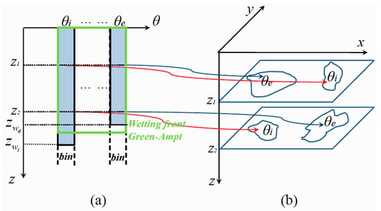
Figure 1.
The mechanism in the Talbot–Ogden model. (a) Bins corresponding to different porosity θ-values compared to the wetting front in the Green–Ampt model; (b) Different moisture content in a soil over the vertical domain.
In Section 2, the Talbot–Ogden model is first introduced, which allows us to create a fast solver to simulate infiltration using finite water content discretization. A detailed sensitivity analysis is then made on the quantitative change of the flux as a function of the number of bins, and this work is generalized to an asymptotic analysis that gives an upper bound for infiltration flux variation. In Section 3, the infiltration flux variation using this model is firstly estimated from the physical parameters of a variety of real soil textures. Infiltration simulations for examples in both coarse and fine soil textures are presented using different numbers of bins to validate the theoretical analysis. Section 4 is the conclusive part.
2. Theory and Methodology
2.1. The Talbot–Ogden Model
Before presenting the Talbot–Ogden model, let us briefly review the Green–Ampt model relevant to it. The Green–Ampt equation [13], which is based on Darcy’s law, provides a very simple model to describe the infiltration of water into the subsurface soil. By neglecting the depth of ponded water, the Green–Ampt equation for vertical infiltration is given by:
where f is the infiltration rate, Ks is saturated hydraulic conductivity, θi is initial moisture content, θd is the maximum moisture content during infiltration, Hc is the effective capillary drive at the wetting front, and F(t) is the cumulative infiltration depth at time t.
The Talbot–Ogden model discretizes the entire water content domain into bins that flow in soils based on the porosity [23] and there is only one vertical spatial dimension (Figure 2) in this model. From the initial moisture content θi to the effective porosity θe there are n bins indexed by j with equal bin width ∆θ. The midpoint value (j − 1)∆θ + ∆θ/2 represented by θj is the moisture content of the j-th bin and the depth of its saturated wetting front is zj. The j-th bin is assumed to be either fully saturated or dry at any depth. The residual moisture content is θr. The rightmost saturated bin is θd. The bins between θd and θe are unsaturated but can become saturated later. In the Green–Ampt model, the cumulative infiltration function F(t) is defined as F(t) = z(θd − θi). If we let f = dF/dt = (θd − θi)dz/dt, the vertical infiltration formula by substituting this expression into Equation (1) is obtained.
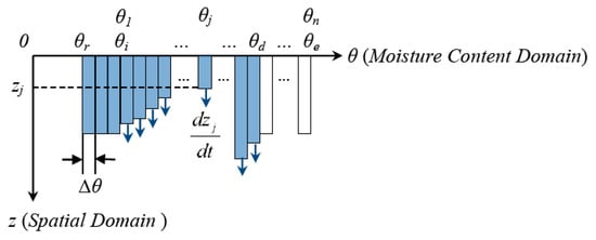
Figure 2.
The infiltration in the Talbot–Ogden model.
Based on Equation (2), the front of the j-bin grows as:
Here, ψ represents the capillary pressure.
The vertical infiltration of water in each bin is governed by Equation (3). The horizontal movement of water through bins is shown in Figure 3. By Equation (3), the infiltration rate dzj/dt is inversely proportional to zj if the other parameters are constant for the j-th bin. Hence, bins to the right tend to have greater front depths than the left ones especially in the beginning of infiltration (Figure 3a).
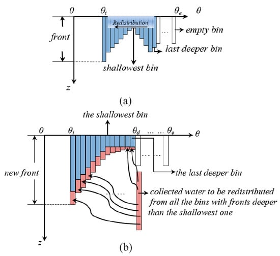
Figure 3.
The redistribution in the Talbot–Ogden model: (a) pre-redistribution and (b) post-redistribution.
Due to the capillary effect in soil, water in bins with large θ-values tends to flow to those bins with smaller θ. This horizontal flow is referred to as the redistribution. It reorganizes the redundant water collected from those protruding wetting fronts in all saturated bins proportional to the values of the capillary pressure ψ(θj) of every bin participating in the redistribution [23]. In the redistribution process (Figure 3b), the last deeper bin is defined as the first saturated bin found over the moisture content domain along the negative direction of the θ-axis whose front depth is higher than the shallowest saturated bin. Note that the wetting front depths gradually decrease from left to right after the redistribution since the capillary pressure in the bins on the left acts immediately on water found at depth in the bins to the right in this model [23].
The reasons for choosing a fixed moisture content θd for both K(θ) and ψ(θ) in Equation (3) are found in [23]. Water tends move downward through the saturated bins with large θ-values, which is the reason that K(θd) is chosen for every bin. However, the capillary pressure in a soil with only lower moisture content than the current saturated bin is always satisfied prior to the rightmost saturated bin, which is the reason that ψ(θd) is chosen for every bin. The functions K(θ) and ψ(θ) are from Brooks and Corey [28], but other soil hydraulic models [29,30,31] can be used without affecting the analysis and conclusions in this paper.
Due to the uncertain discretization of the moisture content domain into n bins, a dynamical system [32] is generated
and
In Equations (4) and (5), the term redist represents the redistribution as the inter-bin movement of water.
The second term of the right hand side in Equation (4) comes from Equation (3) as infiltration. The computation is inexpensive using Equation (4), as for every time step only n ordinary different equations are solved for the infiltration. The simulation of redistribution takes O(n) operations for all n bins. In the numerical convergence test by Talbot and Ogden, the largest n is 400 with a time step size 2.5 s for the coarsest soil sand, which provides a fast, accurate solution.
2.2. Instantaneous Infiltration Rates Analysis
The most important quantity in the Talbot–Ogden model is the bin width ∆θ. Therefore, the range of ∆θ must be selected to match the unsaturated flow in specific soil systems because the flux is nonlinear with respect to ∆θ. There are two simple assumptions made before analyzing the flux: (1). θd is assumed to be fixed and independent of the number of bins, which is reasonable since θd corresponds to the rightmost saturated bin that is changing during the infiltration; (2). All bins with θi ≤ θ ≤ θd are already saturated. If there are empty bins, it means that the surface water can be absorbed in the next time step so that the instantaneous infiltration rate equals the precipitation rate.
The number of bins and its nonlinear influence on the predicted flux can be considered under these assumptions. Now the only uncertain quantity in the Talbot–Ogden model is the number of bins, which means either a finer or a coarser discretization. All other parameters remain constant. The unsaturated flow divides into two steps within every time step: infiltration and redistribution (Figure 4).

Figure 4.
A numerical example: (a) infiltration and (b) redistribution.
The infiltration governs the vertical downward movement of water in every bin. The redistribution governs the horizontal inter-bin flow. The amount of water redistributed to each bin is proportional to the local capillary pressure. In Figure 4, redundant water in the protruding bin caused by infiltration is redistributed to the bins to its left. In the next time step, the process begins with another infiltration followed by redistribution (Equation (4)). These two processes alternate until the simulation completes. The strength of the peak in that particular protruding bin with more infiltration will depend on the bin width ∆θ due to its nonlinearity effect in Equation (4). The redistribution phase moves no surface water downward into the soil by assumption, but only rearranges the wetting fronts in different bins. Due to the properties of the decreasing front depths by the redistribution, an analysis of the instantaneous infiltration rates in the Talbot–Ogden model can be made.
2.2.1. One Bin versus Two Bins
Figure 5 presents the model of one bin and its division into two bins. The rectangle ACHF represents bin1. Its wetting front is FH, its width is ∆θ1, and its depth is z1. Similarly, the two bins in Figure 5 are bin2 (ABJI) and bin3 (BCED) with wetting fronts IJ and DE, respectively. Both their bin widths are equal to ∆θ2, which means ∆θ1 = 2∆θ2. Their front depths are z2 and z3. It is assumed that the entire water content for the two cases is the same. So, the water in bin1 equals that contained in the union of bin2 and bin3, that is . These two cases can be compared. Let VOnebin and VTwobins denote the instantaneous infiltration rates for each case. VOnebin is calculated by
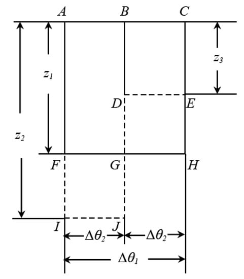
Figure 5.
One bin versus two bins.
VTwobins is calculated by
Based on the capillary pressure of the soil, a relationship among depths exists: z2 > z1 > z3, since left bins always have deeper wetting fronts than the bins to their right. Moreover, if z2 = z3, then splitting one bin into two bins reverts back to the one bin case. Now, the difference between the instantaneous infiltration rates can be computed by subtracting (6) from (7). Thus,
Equation (8) uses . Therefore, when one bin is split into two bins and all possible pores are saturated, additional water infiltrates into the soil faster. Its increment can be bounded by (8). Doubling the number of bins leads to a more continuous flow among bins. Hence, more bins mean a higher infiltration rate. One bin is increased to n bins to prove this assumption.
2.2.2. One Bin versus n Bins
Similarly, n bins can be obtained by equally discretizing the moisture content domain of the one bin case into n pieces. All other parameters remain constant. In Figure 6, the rectangle ABCD represents one bin binX. Its depth and bin width are zX and ∆θX, respectively. Then binX is split into n bins, marked by bin1, bin2, …, binn−1, and binn. All these new bins have the same width ∆θ. Their depths from left to right are z1, z2, …, zn−1 and zn. It is similar to the previous example to have , n∆θ = ∆θX = θd − θi, and z1 ≥ z2 ≥ … ≥ zn. By geometry there exists an index l such that z1 ≥ z2 ≥ … ≥ zl ≥ zX ≥ zl+1 ≥ … ≥ zn. The infiltration rate of binX is
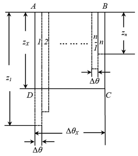
Figure 6.
One bin versus n bins.
For the n-bin case, the summed infiltration rate is
By Equation (9) and Equation (10), the infiltration difference between these two cases is
Note that the last step of Equation (11) uses
Therefore from Equation (11), which means Vnbins − VOnebin ≥ 0, more bins in the model result in a greater infiltration rate.
Now, n1 bins is increased to n2 bins, where n2 and n1 are integers and n2 > n1. This case resembles the extension from one bin to bins. The difference in infiltration rates between these n1 and n2 bins is bounded by . By Equation (11), we can conclude that if a soil texture can be fitted by a finer discretization, its overall conductivity becomes higher in the Talbot–Ogden model. We found the infiltration rate using asymptotic analysis.
2.3. Asymptotic Analyses and Its Physical Meaning
Asymptotic analysis is used when the number of bins increases toward infinity. Equation (11) and the assumption n∆θ = θd − θi are used first:
Before asymptotic analysis, the wetting front curve is loosely assumed to approximate a straight slanted line (Figure 7) in the θ-z domain. This assumption can also be demonstrated by the water content profiles in the solutions of the Richards Equation using Hydrus-1D [27] under many circumstances. Although it is only an approximation, all the wetting fronts in this model decrease from z1 to zn (Figure 6) after redistribution in every time step. When n → ∞, the effect of the number of bins on the instantaneous infiltration rate in the Talbot–Ogden model is:
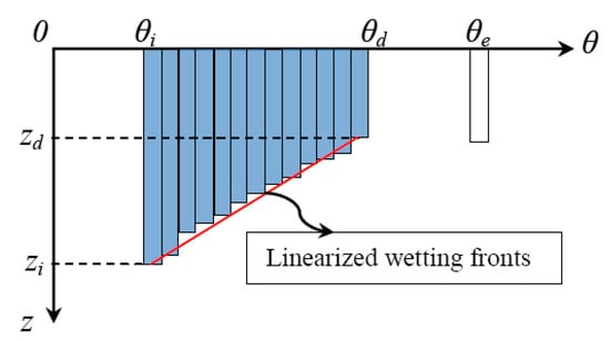
Figure 7.
Approximately linearly decaying wetting fronts.
Equation (14) is obtained by the fundamental law of integration, which is the Newton–Leibniz rule. Summing the reciprocals and then taking the average results in a positive number. Therefore, in the integration the lower bound is 1/zn, and the upper bound is 1/z1.
Moreover, z1 corresponds to the deepest saturated bin, whereas zn corresponds to the shallowest one. For convenience let zi and zd denote these two depths, respectively, because of the moisture content they represent. Thus, when n → ∞,
What Equation (15) tells us is that the variation in infiltration rate depends only on the depths corresponding to the initial porosity θi and the moisture content θd of the rightmost saturated bin. These two special bins are actually the deepest and the shallowest ones, respectively. An interpretation is that the whole wetting front is pushed downward by water in the largest saturated porosity θd and is prevented from progressing by water in the initial moisture content θi. Therefore, the advancement of the wetting front is a compromise between these two bins. Interestingly, the unit of length does not count in the expression, and the quantity is dimensional and is meaningful in physics. However, its value needs some further research, which is crucial for this model. The following practical case is presented: suppose the two wetting fronts satisfy
If then the following limits hold:
and
Therefore, it follows that
Equation (18) means that if the wetting fronts corresponding to the initial moisture content θi and the effective porosity θe are within some distance from each other in depth, the infiltration in the Talbot–Ogden model will eventually become a steady state flow. However, a transformation will make this discussion easier.
Without loss of generality, let zi = rzd with r > 1, then a function D(r) characterizing the difference between Vnbins and VOnebin, is defined by D(r) = ln(r)/(r − 1) − 2/(r + 1). It follows that
The potential maximum or minimum of D(r) can be attained by taking its derivative
which has a zero point at r ≈ 8.16. There are also two limits for two extreme cases:
and
Equation (21) corresponds to the Green–Ampt model. Equation (22) means that if the deepest wetting front is too far away from the shallowest one, then the infiltration rate also tends to the one bin case (Figure 8).
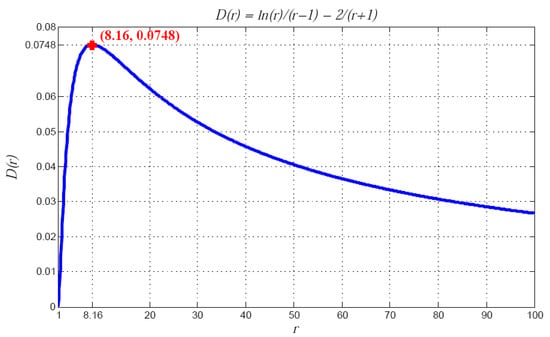
Figure 8.
Ratio r of the deepest wetting front to the shallowest one and its influence on D(r).
The curve in Figure 8 very clearly shows the change in D(r). With the maximum value of D(r), it is able to bound . Note that
where λ denotes the pore size distribution index [14]. If θd = θe, then the hydraulic models used in inequality (23) are unimportant because K(θd) = Ks and ψ(θd) = ψb always hold. In this situation, hence,
the upper bound of the infiltration rate error can be calculated. Note that if a soil texture is chosen, then zd can grow as a function of time and the rainfall rate, therefore making this upper bound decrease with respect to time.
3. Numerical Experiments
In this section, the flux variation upper bound is calculated from the physical parameters of a variety of soil textures. Numerical tests are then carried out to simulate infiltration and verify our analysis in the previous section.
If zd is fixed in Equation (24), what is important is the product of saturated hydraulic conductivity Ks and the bubbling pressure ψb. Therefore, 0.0748∙Ksψb gives a bound for discrepancy of infiltration rates. In Table 1 [23], Ksψb decreases from coarser to finer soils. The one exception is between clay loam and silty clay loam. In general, the upper bound of becomes larger with coarser soils. Significantly, this finding means that if the soil is finer, then the infiltration will not be distinguishable based on a change in the number of bins. However, in coarse textured soil systems, the number of bins is more important than in finer ones. This is the reason why more bins may be required to test the coarser soil: the outcome varies in a wider range.

Table 1.
Parameters of different soil systems.
From the last column of Table 1, if zd is fixed and not too deep nor too shallow, then the value 0.0748∙Ksψb is in fact a certain bound for the variation in infiltration rate. This condition means that if the rainfall rate is around that value or of the same scale for a specific soil system, then the choice of a proper number of bins to make the simulation realistic is needed. Hence, the choice of the number of bins should be determined at least by both the soil and rainfall rates. Note that when zd is very large in inequality (24), the bound becomes small, which means the Talbot–Ogden model acts as the Green–Ampt model or the Richards model for the steady state flow.
Using the Talbot–Ogden method it is possible to simulate this infiltration process by choosing some parameters, including an appropriate number of bins. If the proper number of bins is relatively large, then the modeled soil lets water quickly pass through it, which indicates that an underground reservoir recharges quicker. On the other hand, if fewer bins are needed, then the model indicates that this soil has a good capacity to retain water, which is beneficial for growing plants and for agriculture. In general, the number of bins may indicate the pore size categories that can be modeled in the soil for infiltration.
The comparison of instantaneous infiltration rates computed by Talbot–Ogden method and Hydrus-1D is tested. In this work, the main focus is the influence of the number of bins on the infiltration rates in the Talbot–Ogden method. The soil parameters used are listed in Table 2 [14]. The time step ∆t is set as 10 s for all the simulations to guarantee the comparison consistency. Figure 9 shows the infiltration rate curves corresponding to different numbers of bins for three soil textures. These three types are sand, sandy clay, and silt loam. Different rainfall rates are used because each soil type can generate comparable data only under the proper rainfall rate. One continuous rainfall is one pulse. There are two pulses, and each lasts for 1.5 h. The numbers of bins used in testing are 25, 125, and 250.

Table 2.
Soil textures and parameters used in model evaluation.
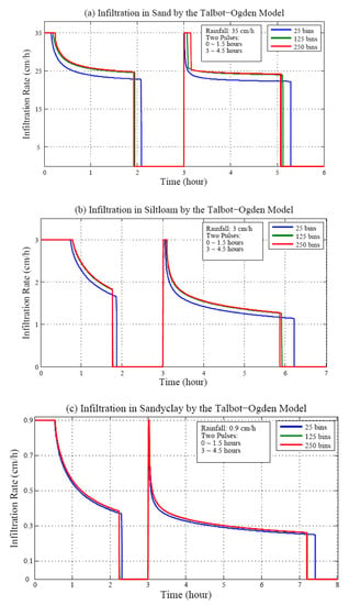
Figure 9.
Comparison of infiltration rates in (a) sand, (b) silt loam, and (c) sandy clay using different numbers of bins.
With an increase in the numbers of bins, the infiltration rate in any soil system rises. During the second precipitation, this phenomenon is even more obvious than in the first one. The reason is explained by the analysis given in Section 2. At the beginning of the second rainfall there are already some dry pores with larger pores that correspond to θ near θe, which is to the right of the moisture content domain. The depth zd is very small at this moment so that the change in infiltration rate is more sensitive to the perturbation of the numbers of bins than that in the first pulse. Mathematically, if zd < 1 cm (the unit is consistent with that in Table 1), the upper bounds given by inequality (24) and Table 1 are relatively easier to approach during the second pulse, thus verifying the analysis in Section 2.
The quadratic or root mean squared (RMS) difference in the instantaneous infiltration rates calculated at every time step with 25 bins and 125 or 250 bins, are defined as
and
where f represents the instantaneous infiltration rates as computed for different numbers of bins, respectively, and N is the number of f values in the interval for which RMS is calculated. In Table 3, the columns of RMS values and their comparisons show that the effect on the infiltration rate becomes smaller with an increase in the number of bins. In the fourth column of Table 3, the decreasing RMS1/RMS2 values indicate that the coarser the soil texture is, the more sensitive the infiltration rate is to the change in the number of bins, especially at the beginning of this change. This phenomenon can be attributed to the relatively large range of infiltration change for coarser soils as shown in Table 1. Note that the root mean square values in Table 3 also satisfy RMS1,2 < 0.0748∙Ksψb.

Table 3.
Influence of the number of bins on the infiltration in the Talbot–Ogden model.
Figure 10a shows how infiltration behaves when the number of bins increases rapidly. There are three arrays of data for comparison: one with 100 bins, another with 500 bins, and the rest with bins. The rainfall rate is set to 2 cm/h, and two pulses are selected with each lasting 1.5 h. Figure 10b shows similar results but with a coarser soil system silt loam. Let N denote the number of time steps where infiltration discrepancies appear corresponding to different numbers of bins, the following equation is used to calculate the influence of the rapid increase in the number of bins:
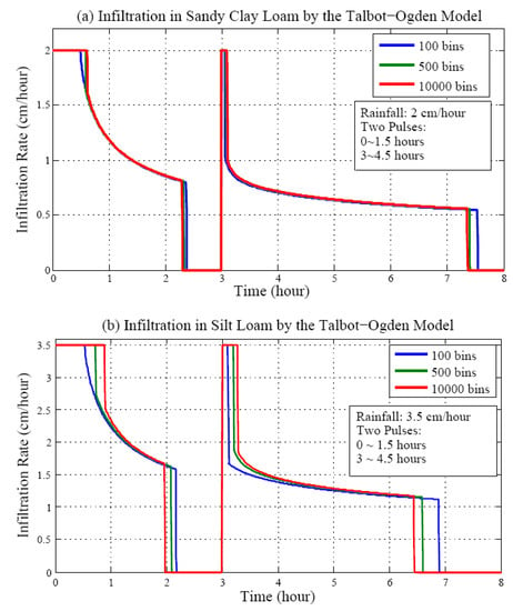
Figure 10.
Infiltration in (a) sandy clay loam, and (b) silt loam with a large increase in the number of bins.
For the three cases in Figure 10a,b, the use of (27) yields Table 4. In Table 4, for sand clay loam, the difference in average infiltration rates using 100 bins and bins is

Table 4.
Influence of large number of bins on the infiltration rate compared with 100 bins as the baseline.
Similarly, for silt loam, their difference is
In Equations (28) and (29) show that if the number of bins increases by 100 times, then the increment in the infiltration rates is still bounded by the data in Table 1. In fact, the increment of infiltration rate is more significant from 100 bins to 500 bins. These results show that infiltration in the finer soil system is less sensitive to the rapid increase in the number of bins than the coarser one, which is consistent with the analysis in Equation (24) and Table 1.
4. Conclusions
A sensitivity analysis of the instantaneous infiltration rates in the Talbot–Ogden model is developed with rigorous mathematical deduction and reasonable physical assumptions. This analysis starts from the two-bin case to the n-bin case. It is concluded that the infiltration rate increases with finer discretization in the moisture content domain. Numerical experiments on the overall infiltration rates have confirmed this theoretical conclusion. Therefore, the choice of the number of bins is very important for different soil textures. When θd approaches θe, the Talbot–Ogden model always generates higher infiltration fluxes than the Green–Ampt model, where K = Ks and Hc = −ψb are set.
An asymptotic analysis is also made on estimating the largest infiltration rates. Using the loose assumption of a line-shaped wetting front, the asymptotic analysis provides an upper bound of the infiltration rate difference resulting from two arbitrarily different moisture content discretizations. The numerical experiments then illustrate this result. These upper bounds for different soil textures can determine the accuracy of the Talbot–Ogden model in predicting the fluxes in various environments. Note that if the wetting front is apparently nonlinear, which is possible in the Talbot–Ogden model especially when precipitations are intermittent, then this asymptotic analysis may be adjusted to be piecewise for different intervals of the moisture content domain. The nonlinearity can be handled using exponential functions (i.e., zα, α > 1) to approximate the depths of the wetting fronts.
There are basically two factors determining the infiltration rates in the Talbot–Ogden model. One is the number of bins by the n-bin case analysis and the other is the front depth discrepancy between the leftmost bin and the rightmost bin in our asymptotic analysis. Moreover, it is intrinsically mass conservative and is always computable.
The analysis will be extended to predicting the infiltration rate variation as a function of time but not only restricted to the instantaneous moment. Meanwhile, bugs and cracks can be easily incorporated into this model, although this will make the flux analysis more complicated. This model can also be extended to heterogeneous soil textures by solving stacked homogeneous soil layers, which is future work.
Author Contributions
In this study, L.L. has made contributions to conceptualization, formal analysis, data curation, investigation and writing-review and editing. H.Y. has made his contributions to methodology, software, formal analysis, resources, and writing-original draft. Both authors have acquired funds for this research.
Funding
This research was sponsored by the Natural Science Foundation for Young Scientists of Jiangsu Province (grant no. BK20180450), the Natural Science Foundation of Nanjing University of Posts and Telecommunications NUPTSF (grant no. NY219080) and the China Postdoctoral Science Foundation (grant no. 2018T110531).
Acknowledgments
The authors gratefully acknowledge the assistance of Talbot, Ogden and Craig Douglas for their extraordinary insights and comments in the development of this paper. The authors also thank King Abdullah University of Science and Technology for the support on computational resources.
Conflicts of Interest
The authors declare no conflict of interest.
Physical Notations and Units
| Variable | Physical Meaning | Unit |
| Ks | Saturated hydraulic conductivity | [LT−1] |
| K | Hydraulic conductivity | [LT−1] |
| ψb | Bubbling pressure | [L] |
| ψ | Capillary pressure | [L] |
| Hc | Suction head/Effective capillary pressure | [L] |
| θ | Moisture content or porosity | [L3L−3] |
| θi | Initial moisture content | [L3L−3] |
| θd | The maximum moisture content during infiltration | [L3L−3] |
| θe | Effective moisture content | [L3L−3] |
| θr | The residual water content | [L3L−3] |
| ∆θ | Bin width after discretization | [L3L−3] |
| f, V | Infiltration rate | [LT−1] |
| F | Total water in soil | [L] |
| t | Time | [T] |
| z | Infiltration depth | [L] |
| zd | Front depth of the bin associated with θd | [L] |
| Front depth of the bin associated with θe | [L] | |
| Front depth of the bin associated with θi | [L] |
References
- De Vries, J.J.; Simmers, I. Groundwater recharge: An overview of processes and challenges. Hydrogeol. J. 2002, 10, 5–17. [Google Scholar] [CrossRef]
- Sanford, W. Recharge and groundwater models: An overview. Hydrogeol. J. 2002, 10, 110–120. [Google Scholar] [CrossRef]
- Smith, R.P. Geologic setting of the Snake River plain aquifer and vadose zone. Vadose Zone J. 2004, 3, 47–58. [Google Scholar] [CrossRef]
- McElroy, D.L.; Hubbell, J.M. Evaluation of the conceptual flow model for a deep vadose zone system using advanced Tensiometers. Vadose Zone J. 2004, 3, 170–182. [Google Scholar] [CrossRef]
- Wilson, L.G. Monitoring in the vadose zone part I: Storage changes. Gr. Water Monit. Remediat. 1981, 1, 32–41. [Google Scholar] [CrossRef]
- Charbeneau, R.J. Groundwater Hydraulics and Pollutant Transport; Waveland Press: Long Grove, IL, USA, 2006. [Google Scholar]
- Manenti, S.; Amicarelli, A.; Todeschini, S. WCSPH with limiting viscosity for modeling landslide hazard at the slopes of artificial reservoir. Water 2018, 10, 515. [Google Scholar] [CrossRef]
- Sophecleous, M. Interactions between groundwater and surface water: The state of the science. Hydrogeol. J. 2002, 10, 52–67. [Google Scholar] [CrossRef]
- Huang, J.; Liao, W.; Li, Z. A multi-block finite difference method for seismic wave equation in auxiliary coordinate system with irregular fluid–solid interface. Eng. Comput. 2018, 35, 334–362. [Google Scholar] [CrossRef]
- Richards, L.A. Capillary conduction of liquids in porous mediums. Physics 1931, 1, 318–333. [Google Scholar] [CrossRef]
- Celia, M.A.; Bouloutas, E.T. A general mass-conservative numerical solution for the unsaturated flow equation. Water Resour. Res. 1990, 26, 1483–1496. [Google Scholar] [CrossRef]
- Schneid, E.; Knabner, P.; Radu, F. A priori error estimates for a mixed finite element discretization of the Richards’ equation. Numer. Math. 2004, 98, 353–370. [Google Scholar] [CrossRef]
- Green, W.H.; Ampt, C.A. Studies on soil physics. J. Agric. Sci. 1911, 4, 1–24. [Google Scholar] [CrossRef]
- Rawls, W.J.; Asce, M.; Brakensiek, D.L.; Miller, N. Green–Ampt infiltration parameters from soils data. J. Hydraul. Eng. 1983, 109, 62–70. [Google Scholar] [CrossRef]
- Huyakorn, P.S.; Pinder, G.F. Computational Methods in Subsurface Flow; Academic Press: New York, NY, USA, 1983. [Google Scholar]
- Haverkamp, R.; Vauclin, M.; Touma, J.; Wierenga, P.J.; Vachaud, G. A comparison of numerical simulation models for one-dimensional infiltration. Soil Sci. Soc. Am. J. 1977, 41, 285–294. [Google Scholar] [CrossRef]
- Grimaldi, S.; Petroselli, A.; Romano, N. Green–Ampt curve-number mixed procedure as an empirical tool for rainfall-runoff modeling in small and ungauged basins. Hydrol. Process. 2012. [Google Scholar] [CrossRef]
- Freyberg, D.L.; Reeder, J.W.; Franzini, J.B.; Remson, I. Application of the Green-Ampt Model to infiltration under time-dependent surface water depths. Water Resour. Res. 1980, 16, 517–528. [Google Scholar] [CrossRef]
- Zadeh, K.S.; Shirmohammadi, A.; Montas, H.J.; Felton, G. Evaluation of infiltration models in contaminated landscape. J. Environ. Sci. Health Part A 2007, 42, 983–988. [Google Scholar] [CrossRef] [PubMed]
- Voller, V.R. On a fractional derivative form of the Green–Ampt infiltration model. Adv. Water Resour. 2011, 34, 257–262. [Google Scholar] [CrossRef]
- Barry, D.A.; Parlange, J.Y.; Li, L.; Jeng, D.S.; Crapper, M. Green–Ampt approximations. Adv. Water Resour. 2005, 28, 1003–1009. [Google Scholar] [CrossRef]
- Gerolymatou, E.; Vardoulakis, I.; Hilfer, R. Modeling infiltration by means of a nonlinear fractional diffusion model. J. Phys. D Appl. Phys. 2006, 39, 4104–4110. [Google Scholar] [CrossRef]
- Talbot, C.A.; Ogden, F.L. A method for computing infiltration and redistribution in a discretized moisture content domain. Water Resour. Res. 2008, 44. [Google Scholar] [CrossRef]
- Ogden, F.L.; Lai, W.; Steinke, R.C.; Zhu, J.; Talbot, C.A.; Wilson, J.L. A new general 1-D vadose zone flow solution method. Water Resour. Res. 2015, 51, 4282–4300. [Google Scholar] [CrossRef]
- Yu, H.; Douglas, C.C.; Ogden, F.L. A new application of dynamic data driven system in the Talbot-Ogden model for groundwater infiltration. Procedia Comput. Sci. 2012, 9, 1073–1080. [Google Scholar] [CrossRef][Green Version]
- Yu, H.; Deng, L.; Douglas, C.C. An extension of the Talbot-Ogden hydrology model to an affine multi-dimensional moisture content domain. J. Algorithms Comput. Technol. 2013, 7, 271–286. [Google Scholar] [CrossRef]
- Simunek, J.; van Genuchten, M.T.; Sejna, M. The HYDRUS Software Package for Simulating the Two-and Three-Dimensional Movement of Water, Heat, and Multiple Solutes in Variably-Saturated Media, Technical Manual, 1st ed.; PC Progress s. r. o.: Prague, Czech Republic, 2006. [Google Scholar]
- Brooks, R.H.; Corey, A.T. Properties of porous media affecting fluid flow. J. Irrig. Drain. Div. Proc. Am. Soc. Civ. Eng. 1966, 92, 61–88. [Google Scholar]
- Van Genuchten, M.T. A closed-form equation for predicting the hydraulic conductivity of unsaturated soils. Soil Sci. Soc. Am. J. 1980, 44, 892–898. [Google Scholar] [CrossRef]
- Durner, W. Hydraulic conductivity estimation for soils with heterogeneous pore structure. Water Resour. Res. 1994, 30, 211–223. [Google Scholar] [CrossRef]
- Kosugi, K. Lognormal distribution model for unsaturated soil hydraulic properties. Water Resour. Res. 1996, 32, 2697–2703. [Google Scholar] [CrossRef]
- Yong, P.; Huang, J.; Li, Z.; Liao, W.; Qu, L.; Li, Q.; Liu, P. Optimized equivalent staggered-grid FD method for elastic wave modelling based on plane wave solutions. Geophys. Suppl. Mon. Not. R. Astronom. Soc. 2016, 208, 1157–1172. [Google Scholar] [CrossRef]
© 2019 by the authors. Licensee MDPI, Basel, Switzerland. This article is an open access article distributed under the terms and conditions of the Creative Commons Attribution (CC BY) license (http://creativecommons.org/licenses/by/4.0/).