Article

Fossil Diesel, Soybean Biodiesel and Hydrotreated Vegetable Oil: A Numerical Analysis of Emissions Using Detailed Chemical Kinetics at Diesel Engine Like Conditions

by
Leonel R. Cancino
1,*,
Jessica F. Rebelo
1,
Felipe da C. Kraus
1,
Eduardo H. de S. Cavalcanti
2,
Valéria S. de B. Pimentel
2,
Decio M. Maia
2 and
Ricardo A. B. de Sá
2
1
Internal Combustion Engines Laboratory (LABMCI), Joinville Technological Center (CTJ), Federal University of Santa Catarina (UFSC), Rua Dona Francisca 8300, Joinville 89219-600, SC, Brazil
2
Instituto Nacional de Tecnologia, Av. Venezuela, 82–Praça Mauá, Rio de Janeiro 20081-312, RJ, Brazil
*
Author to whom correspondence should be addressed.
Atmosphere 2024, 15(10), 1224; https://doi.org/10.3390/atmos15101224
Submission received: 7 September 2024 / Revised: 21 September 2024 / Accepted: 26 September 2024 / Published: 14 October 2024
(This article belongs to the Special Issue Recent Advances in Mobile Source Emissions (2nd Edition))

Abstract

:
Nowadays, emissions from internal combustion engines are a relevant topic of investigation, taking into account the continuous reduction of emission limits imposed by environmental regulatory agencies around the world, obviously as the result of earnest studies that have pointed out the impact on the human health of high levels of contaminants released into the environment. Over recent years, the use of biofuels has contributed to attenuating this environmental issue; however, new problems have been raised, such as NOx emissions tend to increase as the biofuel percentage in the fuel used in engines increases. In this research, the emissions of a compression ignition internal combustion engine modeled as a variable volume reactor with homogeneous combustion were numerically investigated. To analyze the combustion process, a detailed kinetics model tailored specifically for this purpose was used. The kinetics model comprised 30,975 chemical reactions involving 691 chemical species. Mixtures of fuel surrogates were then created to represent the fuel used in the Brazilian fuel marketplace, involving (i) fossil diesel—“diesel A”, (ii) soybean diesel—“biodiesel”, and (iii) hydrotreated vegetable oil— “HVO”. Surrogate species were then selected for each of the aforementioned fuels, and blends of those surrogates were then proposed as mixture M1 (diesel A:biodiesel:HVO—90:10:0), mixture M2 (diesel A:biodiesel:HVO—85:15:0), and mixture M3 (diesel A:biodiesel:HVO—80:15:5). The species allowed in the kinetics model included all the fuel surrogates used in this research as well as the target emission species of this study: total hydrocarbons, non-methane hydrocarbons, carbon monoxide, methane, nitrogen oxides, carbon dioxide, soot, and soot precursors. When compared to experimental trends of emissions available in the literature, it was observed that, for all the proposed fuel surrogates blends, the numerical approach performed in this research was able to capture qualitative trends for engine power and the target emissions in the whole ranges of engine speeds and engine loads, despite the CO and NOx emissions at specific engine speeds and loads.

1. Introduction

Emissions from internal combustion (IC) engines are one of the most important issues related to the transportation industry because of the environmental aspects related to greenhouse gas emissions and climate change and their influences on human health [1,2,3]. The Statistical Review of World Energy report [4] indicated that 596.15 EJ (14,214.9 Mtoe) were consumed worldwide in 2021, 184.21 EJ (4,399.8 Mtoe) of which corresponded to energy coming from petroleum since about 70% of petroleum production is consumed in IC [5], so around 3080 Mtoe were used throughout 2021 in internal combustion engines. A recent greenhouse gas emissions report [6] showed that from 2005 to 2020, the tons of carbon dioxide equivalent (CO2e) emissions from the transport sector contributed about 16.45% of the total CO2e per year emissions considering the main sectors (electricity and heat, transport, manufacturing and construction, agriculture, fugitive emissions, industry, buildings, waste, aviation and shipping, and other fuel combustion). The peak occurred in 2018, with about 17.20%, and the CO2e contribution was around 15.49% in 2020. Effectively, the environmental regulations have contributed to slowing down global oil consumption, forcing the industry to seek different solutions in terms of emissions mitigation and new fuel developments. The use of renewable fuels has been rising over the last decades, with several reports in the literature showing promising and assessed techniques for biodiesel production [7,8,9,10], going from the first to the fourth biodiesel generations (1st—Edible biomass, 2nd—Non-Edible Biomass, 3rd—Algal Biomass, and, 4th—Chemical Processing), thus contributing to slowing down fossil fuel consumption and the carbon dioxide equivalent (CO2e) emissions released into the environment. The transport industry has accompanied this process, and internal combustion engines initially developed for fossil fuels have been adapted for using renewable fuels. Research centers worldwide have been adapting IC to biofuels by employing both experimental and numerical approaches. Proof of this is the rising number of publications reporting numerical and experimental data of IC fueled with renewable fuels [11,12,13]. IC emissions are related to the engine operating conditions and the fuel used [14]. Fossil fuels used in heavy-duty engines such as diesel are mixtures composed of hundreds of chemical species containing several chemical groups involving paraffin (normal and branching), aromatics, olefins, naphthenes, and a parcel of oxygenated fuels in Brazil. Soybean biodiesel and hydrogenated vegetable oil (HVO), first and second-generation biofuels, respectively, were studied in the present research. Due to their complementary performance characteristics, there is great interest from the Brazilian fuel regulation authorities (ANP) in using them complementarily and to assess their performance in vehicular diesel applications as blends to fossil diesel. Soybean biodiesel is a Fatty Acid Methyl Ester (FAME) mainly composed of methyl palmitate (C17H34O2), methyl stearate (C19H38O2), methyl oleate (C19H36O2), methyl linoleate (C19H34O2), and methyl linoleate (C19H32O2) [9,10,15,16]. Hydrogenated vegetable oil is mainly composed of branched and normal paraffin [17,18]. The large number of chemical species renders the combustion modeling of real fuels/biofuels intractable [19]. To overcome this issue, fuel surrogate mixtures are created for research purposes in an attempt to emulate the combustion process of a real fuel (hundreds of species, most without kinetics models/characterizations) by using a reduced number of well-characterized chemical species [20]. Several strategies have been developed to define the composition of a surrogate mixture: (i) physical surrogates, in which case the focus is on tunning the physical properties of the blend to those of the real fuel; (ii) chemical surrogates, with a focus on tunning the chemical properties of the blend to those of the real fuel; (iii) physicochemical surrogates, with a focus on tunning both the physical and chemical properties of the blend to those of the real fuel. Additionally, some formulations focus on fundamental combustion experiments (combustion behavior such as laminar flame speed, ignition delay time, speciation, etc.) [21,22,23]. Nowadays, the formulation of a surrogate mixture that meets all requirements (i.e., physical, chemical, and combustion characteristics) to match a real fuel is not possible. It should be noted that the chemical kinetics of fossil fuels are only partially known despite over one century of fossil fuel use in IC. Detailed kinetics models may be found in the literature for pure chemical species or mixtures of up to six to nine compounds called “fuel surrogates” [24,25,26]. The scenario is worse for biofuels, with few detailed kinetics models reported in the literature involving more than four compounds. The trend is that the greater the number of atoms in the real fuel (average chemical formula), the more significant the number of chemical species that must be used in a surrogate mixture to accurately represent the combustion of the real fuel. In theory, fuel surrogates (or surrogate mixtures) need to have physicochemical, kinetics, and thermodynamic properties similar to those of the real fuel; however, this is almost never possible in practice. Additional information on fuel surrogates may be found in [19,27,28,29,30]. Depending on the focus of a numerical simulation, one of three numerical approaches is usually chosen: (a) Zero-dimensional thermodynamic models, (b) Quasi-dimensional models, and (c) Computational fluid dynamics models with chemical reactions—CRFD. Figure 1 didactically shows the differences between the three approaches.
Zero-dimensional thermodynamic models (Figure 1a) are the most commonly used route as a starting point in the research and development of internal combustion engines [33], and Merker et al. [31] presented an expanded discussion of each of the three approaches shown in Figure 1. Several engine performance parameters may be acquired from the simple modeling of engine components to obtain classical curves relating pressure and volume (p,V) and temperature and entropy (T,s) [14,34,35], with which the cycle work and cycle heat [36] are obtained. In the combustion process, reactants undergo chemical transformations including the formation and depletion of intermediary species and the formation of stable species, which include pollutants, so chemical transformations must be described by the choice of a kinetics model. There are two boundaries to choose from: (i) global kinetics models, (ii) detailed kinetics models, or something in between (e.g., reduced models, skeletal models, semi-detailed models) [33]. Global models widely used in Computational Reactive Fluid Dynamics (CRFD) attempt to represent the kinetic evolution of a fuel using one or two chemical reactions, rendering the CRFD approach viable. However, having few chemical species limits the prediction of results in terms of the concentration of combustion products and, mainly, pollutant emissions, even though most of these models can predict consistent temperature and pressure values throughout the combustion process. Usually, global kinetics models are plausible for stoichiometries around ϕ = 1.0, as shown by Westbrook and Dryer [37]. On the other hand, depending on the number of atoms in the fuel for which the mechanism was developed, detailed kinetics models may vary regarding the number of species and chemical reactions. For example, for methane (four atoms), the GRIMech 3.0 mechanism [38] presented 53 species among 325 reactions. In the case of i-octane (26 atoms), the mechanism detailed by Curran et al. [25] presented 3606 chemical reactions involving 857 chemical species. The premise of the detailed kinetic mechanisms is as follows: “The greater the number of chemical species and elementary reactions, the more significant the chance of obtaining accurate predictions of thermodynamic states (e.g., X i , p, T, H, U, S, etc.)”. This premise of detailed kinetics mechanisms demands that each elementary reaction in a kinetics model have physically consistent reaction parameters (pre-exponential coefficient, temperature dependence coefficient, and activation energy). In this paper, a numerical assessment of emissions (THC, NMHCs, CO, CH4, NOx, CO2, soot, and soot precursors) of a compression ignition IC was performed. The engine was assumed to be a homogeneous charge compression ignition (HCCI) engine, and version 3.0 of the CANTERA software [39] was used. Surrogates blends for fossil diesel, soybean biodiesel, and hydrogenated vegetable oil were used as fuel mixtures. The choice of surrogates for the blend mixtures was based on a literature review.

2. Literature Review on Fuel Surrogates, Experiments and Simulations

2.1. Fossil Diesel Surrogates

Table 1 shows several studies reported in the literature, each containing different chemical species as fossil diesel surrogate mixtures. It should be noted that several formulations of diesel surrogates have been used in recent years, from pure chemical species [40] to binary [41], ternary [42], and quaternary mixtures [43], up to mixtures with nine chemical species in their composition [23]. It is interesting to observe that the number of chemical species used to represent (real) fossil diesel combustion processes increases over time, depending on the focus of development of the fuel surrogate.
Liu et al. [42] pointed out that n-heptane is the single-chemical species most used as a diesel fossil surrogate, and several studies in the literature have supported this observation ([32] and references therein), mainly due to the proximity of its cetane number CN ∼53 relative to that of real fossil diesel (40 ≤ CN ≤ 55). Ramirez L. et al. [41] reported that, although it is a simple binary mixture, the mixture of 70% n-decane with 30% 1-methylnaphthalene represents physicochemical and combustion properties well, with a specific mass of ∼798 kg/m3 (20 °C), a cetane number ∼53, and a H/C ratio of ∼1.8. It should be noted that Frassoldati et al. [44] numerically analyzed the same binary mixture with different percentages to evaluate the performance of a skeletal kinetics model compared to experimental data reported in the literature. The main focus of Mueller et al. [29] was the formulation of four surrogate blends of ultra-low sulfur diesel, maximizing the structural similarity of the surrogate hydrocarbons relative to real diesel. As in other research groups worldwide, the fuel surrogates were selected from the set of nine reference diesel fuels (from the Fuels for Advanced Combustion Engines—FACE program) created and characterized under the auspices of the Coordinating Research Council—CRC using funding from the CRC and the US Department of Energy. Liu et al. [42] reported four mixtures of diesel fuel surrogates prepared and tested on a bench engine. The results pointed out advantages and disadvantages of each mixture used under different engine operating conditions in terms of emissions, presenting a tendency/influence (observed by them) on the formation of soot relative to the presence of toluene in the composition of the diesel surrogate mixture formulations. Qian et al. [45] reported three mixtures of diesel surrogates based on their own formulation methodology with the goal of accurately representing the combustion of real diesel in internal combustion engines, in addition to taking into account the physicochemical properties of the mixtures. The authors pointed out that the mixture of five components in the proportion established (21.6% n-hexadecane, 15.5% n-octadecane, 26.0% 2,2,4,4,6,8,8-heptamethylnonane (i-cetane), 20.7% 1-methylnaphthalene, 16.2% decalin, %mol.) was the one that best approximated the experimental values in terms of engine emissions. Yu et al. [46] reported a ternary mixture of diesel surrogates validated in terms of ignition delay time (IDT) in rapid compression machine (RCM) experiments and speciation in flow reactors (Flow Reactor, Jet Stirred Reactor). The authors pointed out that the experimental results of the IDT and speciation for the proposed mixture were close to those obtained for real diesel, thus validating the choice of chemical species (and mixture percentages) in the proposed ternary mixture. The ternary mixture developed by Qian et al. [45] was studied by Bai et al. [47], who numerically analyzed and validated it against experimental data (Ignition delay time—IDT, Laminar Flame Speed—LFS, and speciation) on fundamental combustion benches (Rapid Compression Machine—RCM, High-Pressure Shock Tube—HPST, Jet Stirred Reactor—JSR, Counterflow Reactor—CFT). Additionally, the surrogate was tested in a diesel engine operating in Homogeneous Charge Compression Ignition—HCCI mode. The authors emphasized that, under the experimental validation conditions, the ternary mixture represented the actual diesel combustion process well. It should be noted that no reports on the use of the mixtures reported in this reference in experiments or numerical simulations of fundamental combustion experiments or internal combustion engines were found. Kukkadapu et al. [23] reported another methodology for formulating fuel surrogates, this time using objective functions throughout an optimization process. Their study aimed to improve the auto-ignition prediction of the surrogate mixture, in addition to guaranteeing the physicochemical properties of real diesel. A list of potential candidates for diesel fuel surrogates based on previous research by the same group and the studies by Mueller et al. [29] and Mueller et al. [48] was also reported, with chemical species from the Fuels for Advanced Combustion Engines—FACE program from the Coordinating Research Council—CRC.

2.2. Biodiesel Surrogates

Several studies reported in the literature have indicated that biodiesel is mainly made up of saturated and unsaturated fatty acid methyl esters (FAMEs), with five of such species highlighted as the most present in biodiesels: methyl palmitate (C17H34O2), methyl stearate (C19H38O2), methyl oleate (C19H36O2), methyl linoleate (C19H34O2), and methyl linolenate (C19H32O2) [9,10,15,16]. The literature also includes studies reporting as biodiesel surrogates slightly smaller chemical species (C11–C15) including two oxygen atoms in the molecule [15] and even chemical species with five carbon atoms (and two oxygen atoms) [49]. Additionally, a study was found to include ethanol (two carbon atoms and one oxygen atom) in a small proportion (∼1.0 vol.%) as a substitute for biodiesel [50]. Table 2 lists some selected works reported in the literature involving pure chemical species used as biodiesel surrogates, as well as different formulations involving binary mixtures [51] and mixtures of a biodiesel substitute and fossil diesel [52,53]. Kerras et al. [22] showed a list of various mixtures of chemical species, none of them within the FAME species, such as ternary mixtures of 1-methylnaphthalene, i-cetane, and n-eicosane, varying the percentages of each component in the blend to represent biodiesel/fossil diesel blends, from B5 to B100. It should be noted that no reports on the use of the mixtures reported in this reference in experiments or numerical simulations of fundamental combustion or internal combustion engines were found, however, it should be mentioned that the methodology developed by Kerras et al. [22] for developing physical surrogates is interesting.
Ramirez L. et al. [54] showed a ternary formulation for B30 composed of 30% methyl octanoate (FAME) and two hydrocarbons (one straight-chain and saturated and the other aromatic). De Bortoli and Pereira [50] presented a quaternary mixture involving two FAME species, a straight-chain saturated hydrocarbon (n-heptane), and an oxygenated chemical species (ethanol). Lee et al. [58] showed a quaternary mixture composed only of FAME species. Other works involving pure biodiesel surrogates (methyl decanoate [60], methyl linoleate [61], methyl butanoate [62]) were not listed in Table 2 for simplicity; however, there are many studies published in the literature involving the use of pure chemical species as biodiesel surrogates.

2.3. HVO Surrogates

Hydrotreated vegetable oil (HVO) is basically made up of saturated straight-chain and branched hydrocarbons, in the proportions of ∼10% and ∼90%, respectively, both groups with a number of carbon atoms ranging from 14 to 18 and a cetane index usually greater than ∼70 [17]. It should be observed that HVO is a biofuel made from the hydrogenation of vegetable oil; thus, it is not an alternative or clean fuel. Table 3 presents three studies reported in the literature with formulations of mixtures of HVO surrogates. Alkhayat [18] worked with the formulation of seven HVO surrogate hydrocarbon mixtures, with six ternary mixtures and one binary, involving eight hydrocarbons, six saturated and two unsaturated. In the seven proposed HVO surrogate mixtures in [18], the maximum concentration of branched-chain paraffin did not exceed 30%, thus going against that observed by Bays et al. [17] and Lee et al. [63].
Refs. [17,18] are both relatively recent studies (2022 and 2023, respectively) that show the results of the chromatographic analyses of the HVO samples used in each research. Observing the chromatographic data, it is possible to visualize the antagonistic behavior of the two results in terms of percentage (%) of iso and normal paraffin. Lanfaloni [64] analyzed three mixtures for HVO surrogates involving four chemical species as potential HVO surrogates: n-pentadecane, i-cetane, 2-methyl-pentadecane, and 2-methylheptane. In [64], mixture 3 was closer than the others in terms of the distillation curve, while mixture 2 was closer to the physicochemical properties of HVO. Note that, in the [64], the iso-paraffin proportion is higher, from ∼70% to ∼80%, representing iso-paraffin by i-cetane, thus following the same trend as the data presented by Bays et al. [17]. Luning et al. [21] analyzed five mixtures of chemical species for algal biodiesel surrogates (Hydrotreated Renewable Diesel [HRD]). Depending on the physicochemical and combustion characteristics investigated, it was concluded that the quinary mixture composed of 9.3% n-pentadecane, 13.8% n-hexadecane, 26.5% n-heptadecane, 19.3% n-octadecane, and 31.1% i-dodecane was the one that best represented the algae-based HRD. Note that Lanfaloni [64] and Bays et al. [17] pointed in the same direction in terms of a more significant amount of i-paraffin, while Luning et al. [21] and Alkhayat [18] pointed in the opposite direction, showing higher n-paraffin content.

3. Materials and Methods

3.1. The In-House Cantera-Python Computational Tool for Analysis

In this research, a Python script native to Cantera [39] was used for numerical simulations. This Python script has been improved over recent years by students and researchers at the Federal University of Santa Catarina (UFSC) Internal Combustion Engines Laboratory (LABMCI/CTJ). Figure 2 shows the solution flowchart for the homogeneous charge compression ignition engine. The engine cylinder was considered an adiabatic, variable, and stirred reactor, and the solution was then obtained as a function of time, represented in the simulation as every crank angle (CA) piston position along the four strokes. Additional details of the computational tool used for the simulation may be found in [36].
The cantera-python script does not resolve the full 3D fluid flow field. Thus, turbulence is not modeled, and the fuel is injected in the gas phase, so the spray phenomena are not included/modeled. The combustion is assumed to occur spatially homogeneously in a perfectly stirred reactor (PSR), and the kinetics evolution of the chemical species involved in the process is then represented by a detailed kinetics model described below, allowing all the fuels used as surrogates (see Table 4) as well as the target emissions species of this research (THC, NMHCs, CO, CH4, NOx, CO2, soot, and soot precursors).

3.2. Fuel Surrogates Composition for Numerical Simulations

The compositions of fuel surrogates for fossil diesel, soybean diesel, and HVO were defined depending on their chemical characteristics and compositions in the Brazilian fuel marketplace (Fossil diesel ☞ diesel A) and taking into account the information shown in Table 1, Table 2 and Table 3. For fossil diesel, we used the same formulation as Liu et al. [42]; for soybean biodiesel, we pondered the C/H ratio (1.82), as reported by Rinaldi et al. [65], using the chemical formula of methyl-decanoate, methyl-palmitate, and methyl-linoleate, resulting in a mixture of 11%, 11%, and 78%, respectively. Concerning HVO, the mixture of 10% n-hexadecane and 90% i-cetane was employed, as reported by Bays et al. [17], stemming from chromatographic analyses.
  • Fossil diesel (diesel A): 81% n-docecane, 14% toluene, 5% cyclohexane, with cetane number of CN = 44.3, pointed out as the best surrogates mixture for engine performance and emissions in the work of Liu et al. [42].
  • Soybean diesel (biodiesel): 11% methyl-decanoate, 11% methyl-palmitate, 78% methyl-linoleate, with C/H ratio of 1.82, and reported as soybean biodiesel composition in the work of Rinaldi et al. [65].
  • Hydrotreated vegetable oil (HVO): 10% n-hexadecane, 90% i-cetane, as reported in reference [17].
Once defined the fuel surrogates for fossil diesel, biodiesel and HVO, are then defined the fuel mixtures simulated in this work as follows:
  • Mixture M1 ☞ diesel A:biodiesel:HVO (90:10:0)
  • Mixture M2 ☞ diesel A:biodiesel:HVO (85:15:0)
  • Mixture M3 ☞ diesel A:biodiesel:HVO (80:15:5)
It is important to mention that the mixture ratios of the surrogate blends used in this work attempt to tune characteristics of the real fuel compositions (chemical groups, cetane number, chromatography analysis, etc.) according to Brazilian fuel legislation. Mixture M1 is related to the commercial diesel used in Brazil until March 2023, mixture M2 to the real fuel that will be used in Brazil starting in 2026, and mixture M3 to a planned diesel formulation with HVO addition.

3.3. The Detailed Kinetics Model for Fossil Diesel, Soybean Biodiesel and HVO

The detailed kinetics model used in this work was developed by the CRECK Modeling Group specifically for this research group (Personal communication, Prof. M. Pelucchi and Prof. T. Faravelli, December 2023) at the Department of Chemistry, Materials, and Chemical Engineering of Politecnico di Milano. The model was the result of an adequate blending process of several subsets of chemical kinetics models for pure hydrocarbons and oxygenated species, all of them contained in the real fuels and chosen in the present study as potential fuel surrogates to conform the fuel mixtures. The detailed kinetics model is composed of 30,975 chemical reactions involving 691 chemical species and allows all the chemical species used in this work as fuel surrogates (see Table 4).
The kinetics model allows predicting the target emissions (THC, NMHCs, CO, CH4, NOx, CO2, Soot, and Soot precursors) for the engine under compression ignition-like conditions. In terms of soot modeling, the kinetics model from the CRECK group incorporates the soot modeling reported in [66,67,68], including: (i) Soot precursors: polycyclic aromatic hydrocarbon—PAH, (ii) Particles: pseudo-species with 320 to 4 × 10⁴ carbon atoms and average mass from 4 × 10³ amu to 4.9 × 10⁵ amu, and (iii) Aggregates: pseudo-species with more than 8 × 10⁴ and average mass higher than 9.7 × 10⁵ amu. The chemical kinetics of nitrogen has been documented plenty by Faravelli et al. [69] and Frassoldati et al. [70].

3.3.1. Simulation Parameters and Conditions Used in This Work

For the numerical simulations, engine geometrical parameters and operating conditions were set so as to represent a commercial engine available in the Brazilian marketplace. The engine in question was the ON ROAD F1C (Light Commercial Vehicles) 125kW (170 HP) 3500 rpm—Euro V. Geometrical parameters were used, and operating conditions were estimated/extrapolated. Table 5 shows all the input parameters given to the numerical simulation for the operating conditions simulated in this study.
It should be stressed that when a factory diesel engine works with mixtures of other types of fuel with base diesel, it is necessary to apply variable systems on the engine (variable compression ratio, variable valve timing, exhaust gas recirculation, higher fuel injection pressure, split injection, etc.). This study proposed a simulation to verify the engine performance concerning emissions when employing different blends using the geometric and operating parameters shown in Table 5. It should be noted that the cantera-python script is flexible, covering several engine operating conditions. For example, it is possible to set the fuel injection process in three injection stages. It is important to acknowledge that, in this study, the total fuel mass was injected in two stages for the operating conditions shown in Table 5. The online engine documentation does not inform relevant engine operating parameters such as (a) valve timing, (b) air temperature and pressure after the power boosting system, (c) fuel injection system, and (d) specific fuel consumption. Hence, all operating parameters in Table 5 used for simulations in this research were chosen based on typical engine operating parameters found in the literature for compatible engine performance parameters.

4. Results and Discussion

As shown in Table 5, the engine speed ranged from 1000 rpm to 3000 rpm, with Δ = 250 rpm, resulting in nine simulation points for each mass of injected fuel. The injected fuel ranged from 12.5 × 10 5 kg to 37.5 × 10 5 kg, with Δ = 2.5 × 10 5 kg (11 simulation points); thus, 99 simulations were performed. The total simulation time was ∼90 days (full time) using a desktop computer with 64GB RAM, 3.7 GHz, six cores, and 2TB storage. In this study, nitrogen oxides (NOx) are reported as the summation of NO, NO2, and NO3, the Nonmethane hydrocarbons (NMHCs) are assumed to be the summation of ethane (C2H6), ethene (ethylene C2H4), acetylene (C2H2), propane (C3H8), propene (propylene C3H6), and n-butane (n−C4H10), and the total hydrocarbons (THCs) are assumed to be the summation of non-burned fuel along the cycle (see Table 4) for all the mixtures investigated in this research.

4.1. Number of Cycles Simulated for Engine Stable Operation

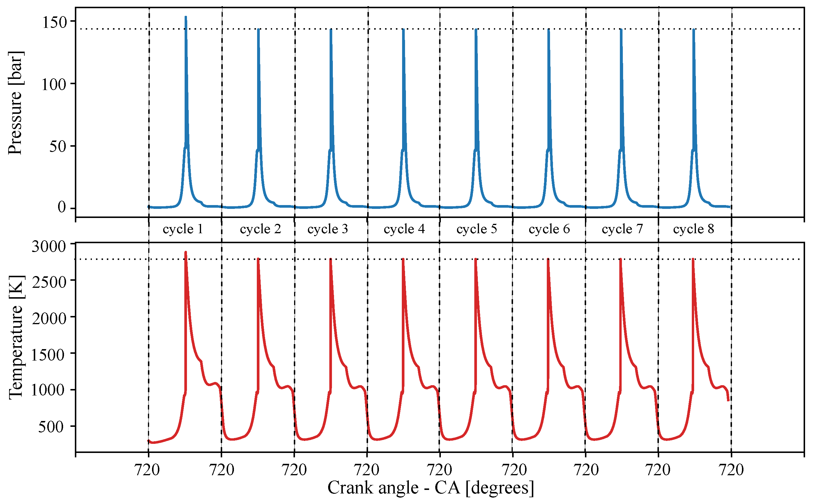
Throughout the engine operation simulation, it is necessary to check the minimum number of consecutive cycles of operation in order to collect converged and stable data on the engine operation. In other words, the pressure and temperature after each cycle will not be the same over the first simulated cycles, so the output collected over the first cycles does not represent stable engine operation data. In the cantera-python script used in this research, the minimum number of engine operation cycles to be simulated was obtained using an iterative procedure, looking at the pressure and temperature peaks, as shown in Figure 3.

4.2. Predicted Engine Expansion Power

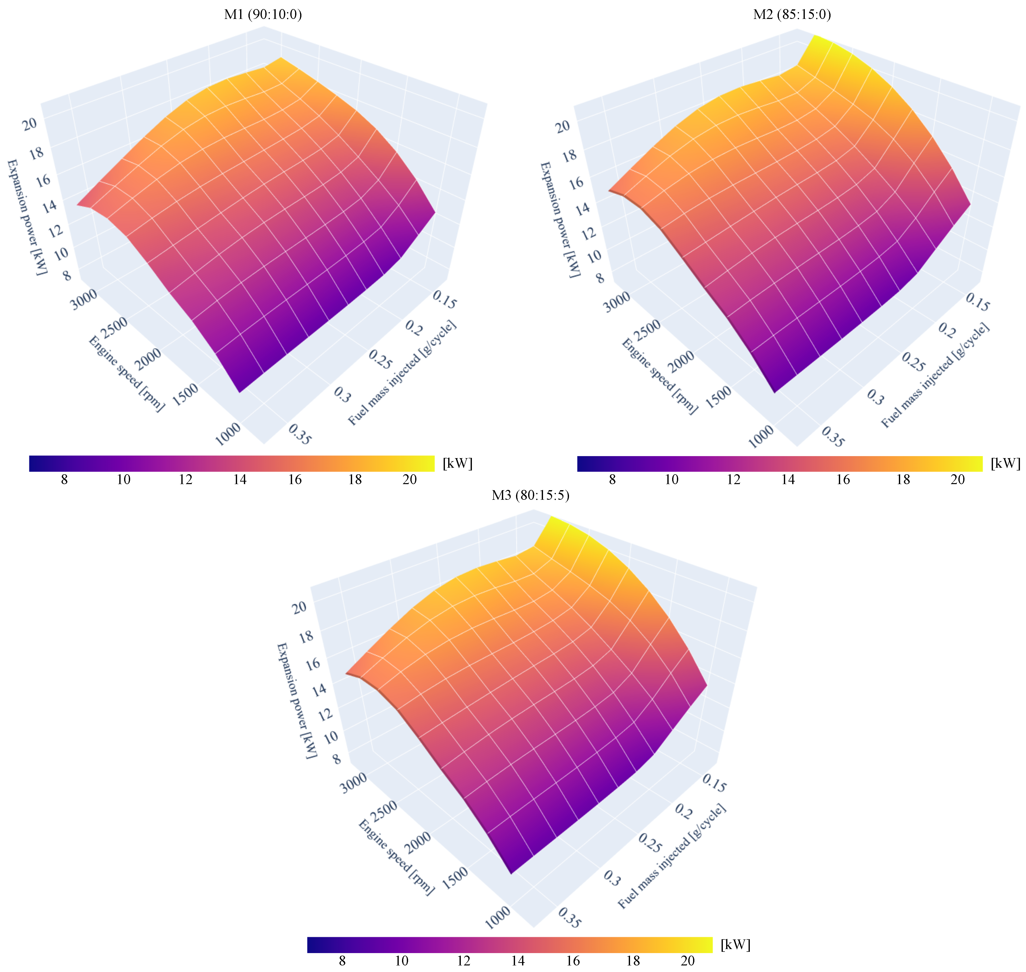
Figure 4 shows the expansion power obtained from simulations though the work per cycle estimated as the area under the p-v diagram and the engine speed [14]. It should be noted that the expansion power in Figure 4 is shown per cylinder and, when compared to the engine in question (four-cylinder—ON ROAD F1C (Light Commercial Vehicles) 125kW (170 HP) 3500 rpm—Euro V), the range of the expansion power from the simulations matches that of the engine brake power. However, it is important to explain that the expansion power values obtained from numerical simulations should be considered as a reference because they do not take into account heat transfer effects, total friction, spray behavior, and other phenomena present in real engine operation (see Section 3.1 for details) not included in the numerical model of this study.
Figure 4 shows the typical behavior of diesel engines. One may observe that the power increases as the engine speed increases until the engine speed is close to the maximum speed, after which the power decreases. For the engine in question, the maximum reported power is in the 3000 rpm to 3500 rpm range (125 kW). In the simulations performed in this study, the maximum power obtained was close to 2750 rpm for all mixtures, and all with close values around 88 kW, 97 kW, and 97 kW (for M1, M2, and M3, respectively) for an injected fuel mass of 0.5 g/cycle. Thus, the specific fuel consumptions at those operating points were 468 g/kWh, 428 g/kWh, and 428 g/kWh for M1, M2, and M3, respectively. It should be noted that the expansion powers obtained in this research are related to the estimated engine operating parameters specified in Table 5.

4.3. Emissions as Function of Engine Speed

As shown in Table 5, the engine speed ranged from 1000 rpm to 3000 rpm, with Δ = 250 rpm, resulting in nine simulation points for each injected fuel mass, which ranged from 0.125 g/cycle to 0.375 g/cycle per cylinder, with Δ = 0.025 g/cycle. In Figure 3, one may observe that only after four to six cycles were there no variations in the pressure and temperature peaks. Numerically, the variation in temperature and pressure peaks was lower than ∼10.0 K and ∼1.5 bar for all the numerical engine simulations; considering the operating conditions estimated in this study, the number of cycles used was 12 (see Table 5). Figure 5, Figure 6 and Figure 7 show comparisons at an engine speed of 2000 rpm for CO, CO2, CH4, and NOx, polycyclic aromatic hydrocarbons (PAH, soot precursors), soot (particles and aggregates), non-methane hydrocarbons, and unburned hydrocarbons for all the mixtures investigated in this research.
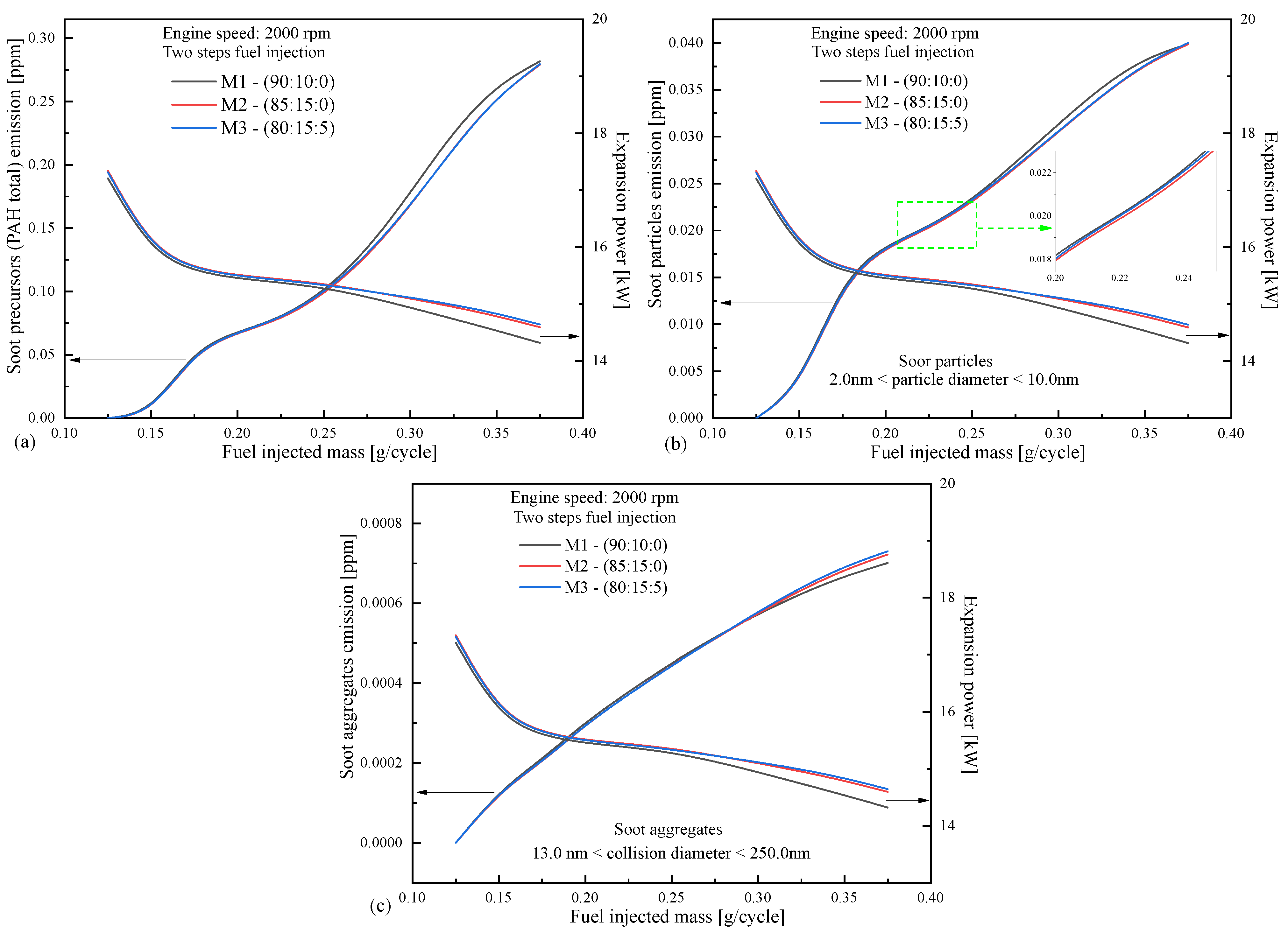
One may observe in Figure 5 that the kinetics mechanism can partially reproduce the qualitative trend of experimental data observed in the literature. Figure 5a shows that for CO emissions and fuel mass injections below 0.15 g/cycle and above 0.275 g/cycle, the qualitative trend of numerical simulations follows the experimental trend of measurements reported in the literature [71,72,73,74,75], and the higher the biodiesel percentage is in mixture, the lower the CO emissions. Within the 0.15 g/cycle to 0.275 g/cycle mass injection range, the production of CO was more significant for the mixture M2 (with a more considerable amount of biofuel). One may note that, as mentioned in Section 3.3.1, the numerical simulations performed in this study assumed static conditions, fixed valve timing and fuel injection parameters (see Table 5) for all fuel injection masses, so the chance of obtaining nonrealistic trend predictions increases. For the CO2 emissions, Figure 5b shows that the numerical results also indicated the experimental trend observed in the literature [71,72,73,74,75] that the more biodiesel there is, the higher the production of CO2 considering all engine speeds and injected fuel masses analyzed in this study. It should be noted that the detailed kinetics model and the engine modeling were consistent with the qualitative trends observed in the literature for diesel engines. For methane emissions, shown in Figure 5c, the numerical simulation returned values qualitatively consistent with experimental data reported in the literature [76,77,78,79]. The higher the biodiesel percentage, the lower the CH4 emissions for all engine speeds and injected fuel masses analyzed in this study. It should be noted that the detailed kinetics model and the engine modeling were consistent with the qualitative trends observed in the literature for diesel engines in terms of methane emission prediction. Figure 5d shows the modeling response for NOx emissions. One may observe that the numerical results are qualitatively consistent with qualitative trends observed in the literature for injected fuel masses below 0.150 g/cycle (from 1750 to 2250 rpm): the higher the biodiesel percentage in the mixture, the higher the NOx emissions [71,72,78,78]. As for the numerical CO emission predictions of this study, the numerical simulations performed assumed static conditions, fixed valve timing and fuel injection parameters (see Table 5) for all fuel injection masses, so the chance of obtaining nonrealistic trend predictions increases. Figure 6 shows the trends for soot precursors and particulate matter in two size ranges (particle diameters from 2 nm to 10 nm, and aggregates with collision diameters from 13 nm to 250 nm). For polycyclic aromatic hydrocarbons (Figure 6a) the numerical results followed the qualitative trend observed in the literature for measurements that adding biodiesel to the mixture reduces the PAH emissions [80], particles (Figure 6b), and aggregates (Figure 6c) [78]. It should be noted that the numerical prediction only failed to agree with the observed experimental trend (from literature) for injected fuel masses over 0.275 g/cycle and aggregates with collision diameters of 13 nm < dc < 250 nm.
Figure 7 shows the results for nonmethane hydrocarbons and unburned hydrocarbons. The numerical simulation using detailed chemical kinetics showed that increasing the amount of biodiesel in the mixture leads NMCH and THC emissions to decrease, as experimentally reported in the literature [72,78,81].
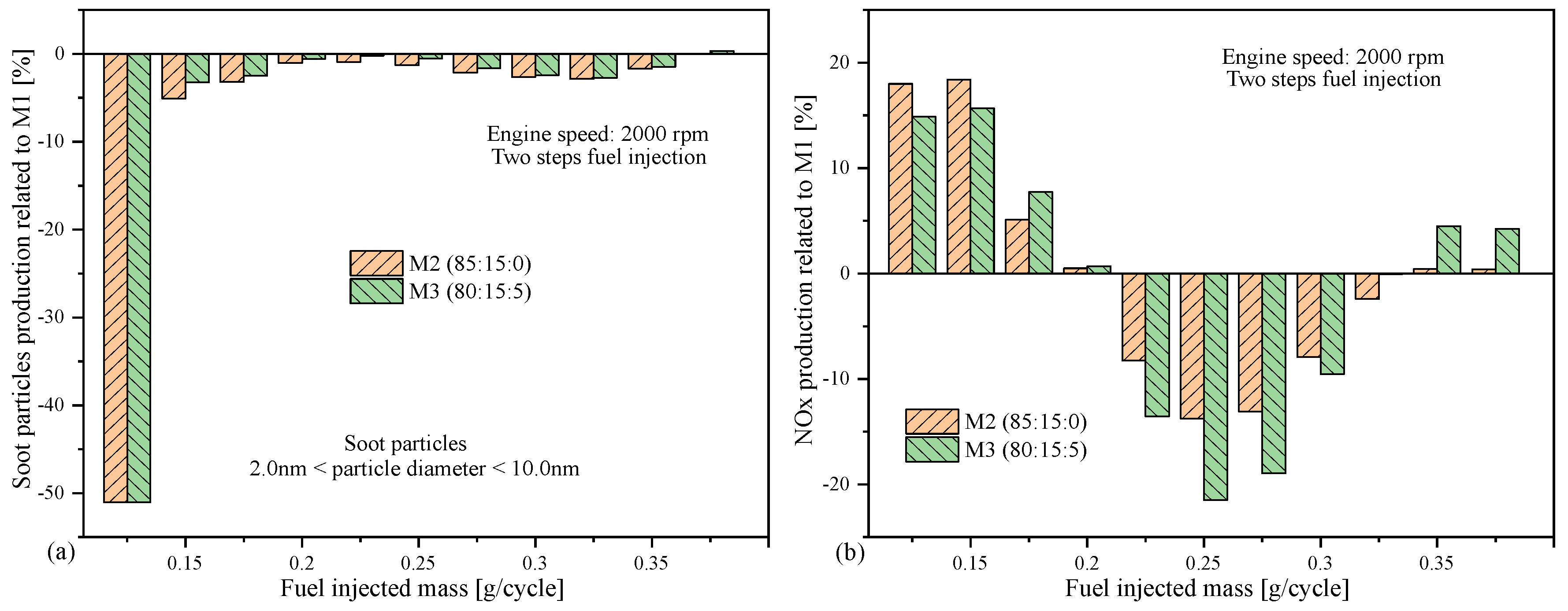
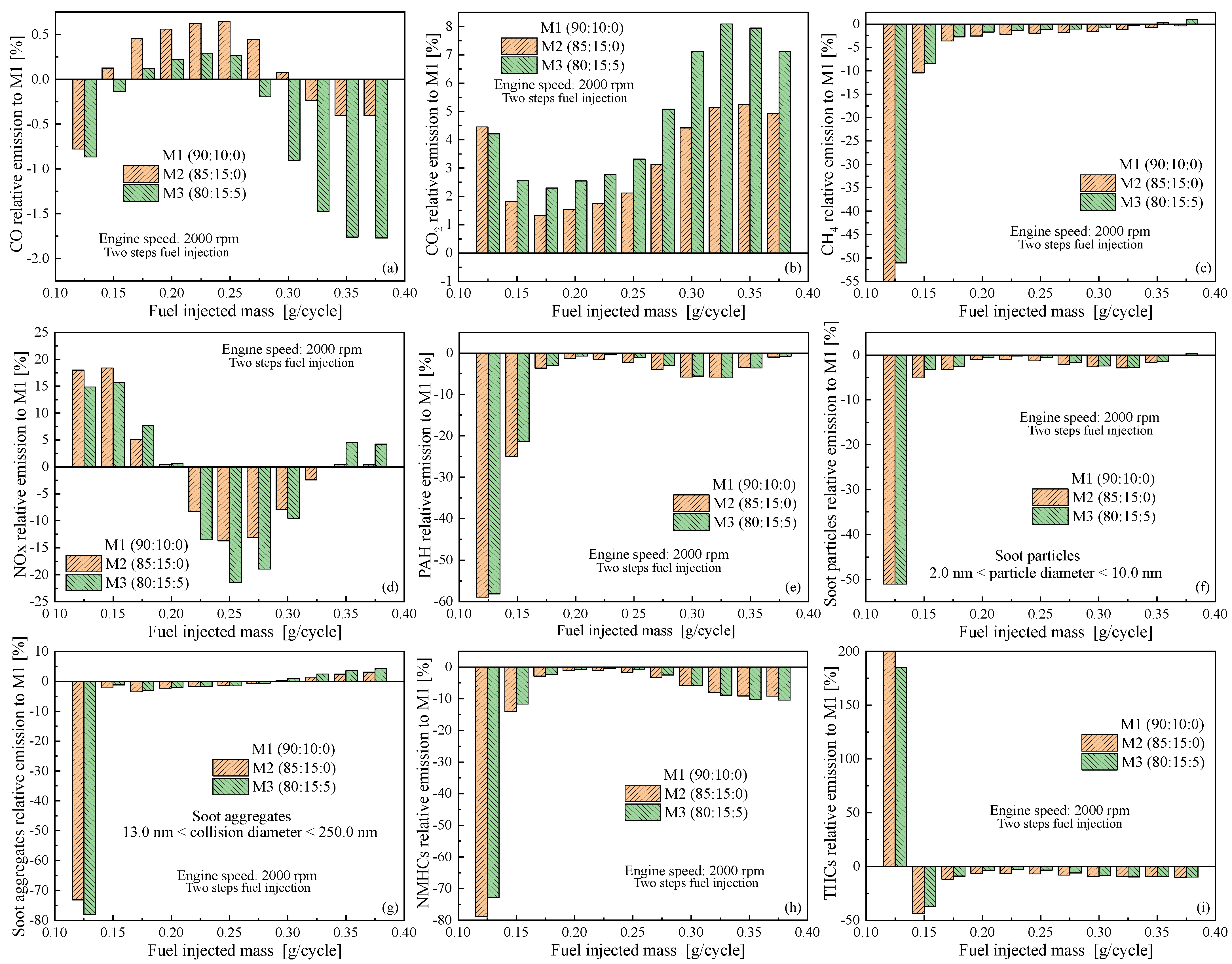
Figure 8 shows the emissions (relative to mixture M1) of soot particles and total NOx of mixtures M2 and M3 at an engine speed of 2000 rpm and covering the full range of injected fuel masses (per cylinder, per cycle). Figure 8a shows the emissions of mixtures M2 and M3 relative to mixture M1 of particles with diameters ranging from 2 nm to 10 nm; as previously mentioned, increasing the biodiesel percentage in the mixture, the numerical response obtained in this simulation study qualitatively agreed with the experimental results reported in the literature for both the mixtures when increasing the biodiesel percentage for mixture M2 and adding HVO for mixture M3 [78].
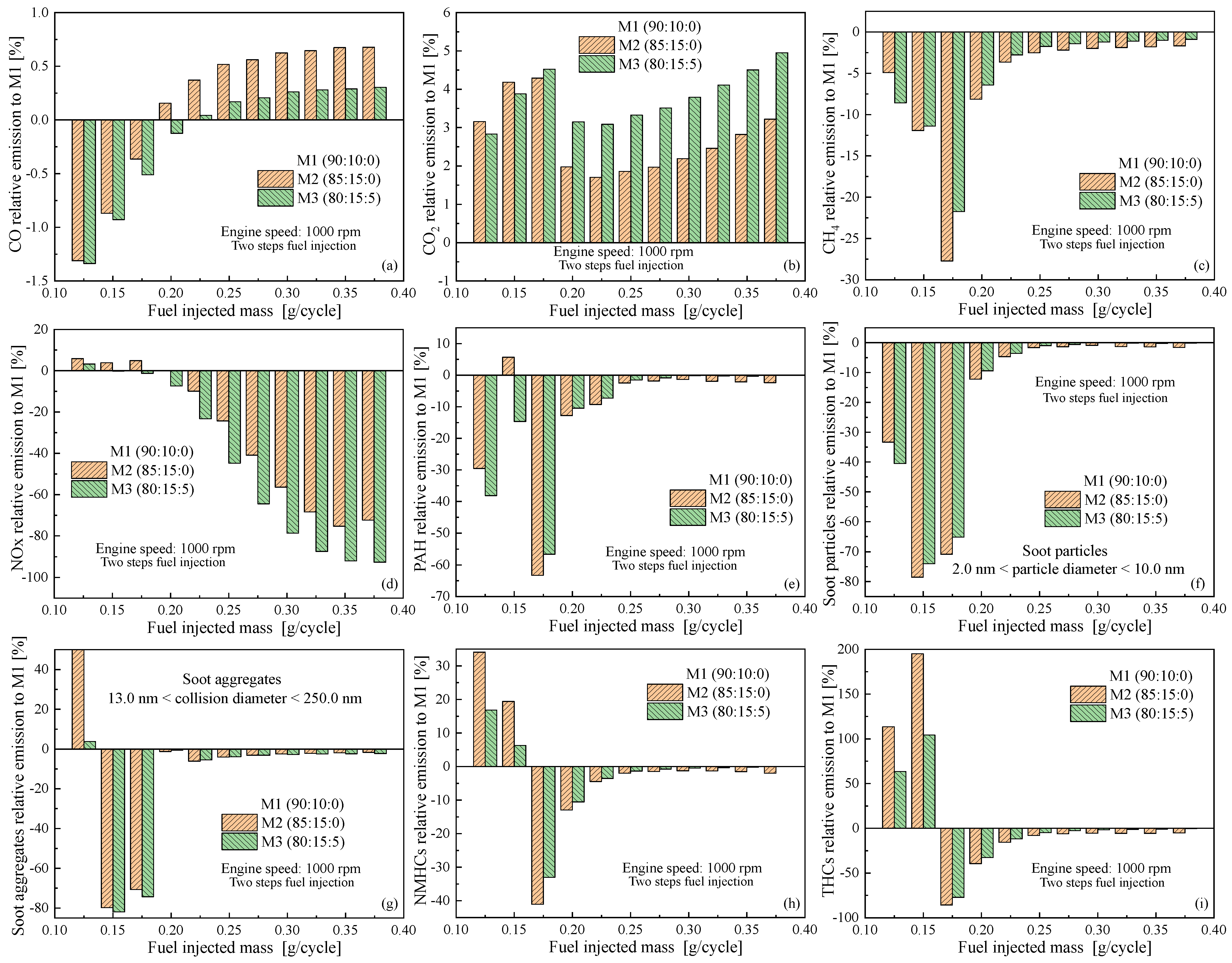
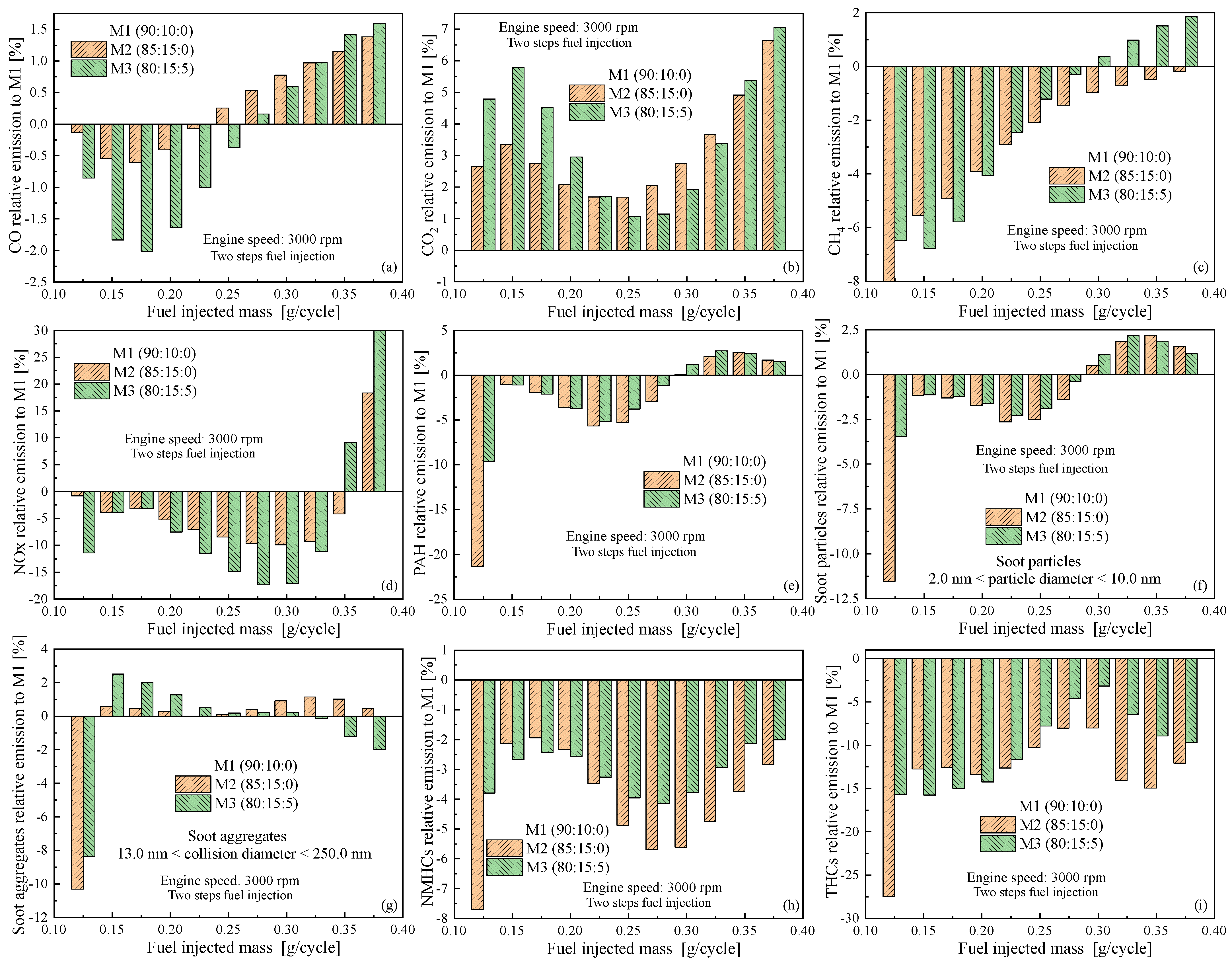
For nitrogen oxides (NOx), shown in Figure 8b, the numerical simulations reported an inversion in behavior depending on the amount of fuel injected (engine load). Most reported experimental data indicate that NOx emissions increase as the amount of biodiesel increases [72,81]. In the present study, for injected fuel masses from 0.125 g/cycle to 0.20 g/cycle, the numerical results followed the experimental trend reported in the literature. However, outside this range, the numerical simulations presented emissions inconsistent with the experimental data (see Figure 8b). As for the numerical predictions of CO emissions made in this study, the numerical simulations performed assumed static conditions, fixed valve timing and fuel injection parameters (see Table 5) for all fuel injection masses, so the chance of obtaining nonrealistic trend predictions increases. To expand the emissions analysis for low and high engine speeds, Figure 9, Figure 10 and Figure 11 show the emissions relative to mixture M1 (commercial diesel in the Brazilian marketplace) of mixtures M2 and M3 for all the estimated engine operating conditions described in Table 5.
It should be noted that Figure 8a and Figure 8b correspond to Figure 10f and Figure 10d, respectively. Comparing Figure 10f and Figure 10d (engine speed of 2000 rpm) to the corresponding emissions at 1000 rpm and 3000 rpm (Figure 9f and Figure 9d and Figure 11f and Figure 11d, respectively), one may observe that the emissions trend changes, as reported in the literature for experimental approaches [76,80]. For a better understanding of the following analysis, the low, average, and high engine speeds in this study are 1000 rpm, 2000 rpm, and 3000 rpm, respectively.
From Figure 9a, Figure 10a and Figure 11a, one may observe that the numerical trend of CO emissions changes as the engine speed increases. It should be noted that, for lower speeds, the prediction range for qualitative CO emissions allowed up to 0.175 g/cycle of injected fuel mass, with this range extended to 0.200 g/cycle of injected fuel mass for high engine speeds. From Figure 9b, Figure 10b and Figure 11b, one may observe that the numerical trend of CO2 emissions also changes as the engine speed increases from low to high. The numerical prediction of this study followed the experimental trend observed in the literature: the higher the biodiesel percentage, the higher the CO2 emissions, with this for all engine speeds [74] and injected fuel masses [77]. The numerical prediction of methane emissions followed the same behavior as CO2 relative to being consistent with the experimental trend, as may be seen in Figure 9c, Figure 10c and Figure 11c. For nitrogen oxides, the modeling performed in this study showed contradictory behaviors for low speed and high loads (injected fuel mass over 0.200 g/cycle), average speed and average loads (injected fuel mass from 0.200 g/cycle to 0.325 g/cycle), and high speed and low and average loads (injected fuel mass below 0.325 g/cycle), as shown in Figure 9d, Figure 10d and Figure 11d. In terms of polycyclic aromatic hydrocarbons, the numerical trend of this research (Figure 9e, Figure 10e and Figure 11e) followed the experimental trend reported in the literature for the entire investigated range of injected fuel mass [80]. The same behavior in terms of qualitative trends was observed for soot particles and aggregates, as shown in Figure 9f, Figure 10f and Figure 11f and Figure 9g, Figure 10g and Figure 11g), respectively. It should be noted that for nonmethane hydrocarbons, the numerical predictions followed the qualitative trend of emissions observed in the available literature for the low and average engine speeds and the entire range of engine loads (injected fuel mass). For high engine speeds, the numerical predictions were not satisfactory for low loads (injected fuel mass under 0.150 g/cycle), as one may observe in Figure 9h, Figure 10h and Figure 11h, respectively. The qualitative trend of total hydrocarbon emissions in the numerical simulations followed the experimental observations for low engine speeds and over the entire range of engine loads (injected fuel mass). The model returned consistent behavior for average engine speeds and injected fuel masses over 0.125 g/cycle and for high engine speeds and injected fuel masses over 0.175 g/cycle, as shown in Figure 9i, Figure 10i and Figure 11i) respectively.
This is a significant point related to the engine model used in this research. It should be noted that the higher the engine speed, the lower the time available for the combustion process, a fact that must be considered in engine development [14,31]. The detailed kinetics model used in this research was able to capture this effect throughout the combustion process at different engine speeds and for different injected fuel masses (per cycle) using different mixtures of diesel surrogates (see Table 5). Clear evidence of the consistent kinetics model performance may be observed in Figure 4, showing different values of expansion power for different mixtures at different engine operating conditions. The same scenario for emissions may be observed when comparing Figure 9, Figure 10 and Figure 11, with different trends for THC, NMHCs, CO, CH4, NOx, CO2, soot, and soot precursors observed depending of the engine speed and injected fuel mass.

5. Conclusions

In this study, a numerical analysis of emissions under diesel engine-like conditions was performed, with a simulation proposed to verify engine performance concerning emissions using different blends and the geometric and operating parameters shown in Table 5. The target emissions were THC, NMHCs, CO, CH4, NOx, CO2, soot, and soot precursors, and a detailed kinetics model with ∼700 chemical species among ∼31,000 elementary reactions was used. The detailed kinetics model was exclusively tailored for the fuel surrogate blends used in this study. The surrogate species were then selected for each of the following mixtures: (i) mixture M1 (diesel A:biodiesel:HVO—90:10:0); (ii) mixture M2 (diesel A:biodiesel:HVO—85:15:0); (iii) mixture M3 (diesel A:biodiesel:HVO—80:15:5). The surrogate blends for the base fuels (diesel A, biodiesel, and HVO) where selected as follows: (i) Fossil diesel (diesel A): 81% n-docecane, 14% toluene, 5% cyclohexane; (ii) Soybean diesel (biodiesel): 11% methyl-decanoate, 11% methyl-palmitate, 78% methyl-linoleate; (iii) Hydrotreated vegetable oil (HVO): 10% n-hexadecane, 90% i-cetane. The choice of pure species (and percentages) in the surrogates was supported by the extensive literature review performed in this study and was made in function of the main components of the base fuels (diesel A, biodiesel, and HVO) in the Brazilian marketplace. When compared to experimental emission trends available in the literature, it was possible to conclude that the numerical approach performed in this study was able to capture qualitative trends for engine power and the target emissions for all the proposed fuel surrogate blends in all engine speeds and engine loads, except for CO and NOx emissions at specific engine speeds and loads. As a result of the numerical prediction consistency when data was compared to the experimental trends available in the literature, it may be concluded that the method used in this study could be used for research involving other surrogate blends with different percentages of compounds in order to predict the behavior of new fuel formulations in terms of emissions as well as engine performance. Analyses and results of combustion processes in internal combustion engines are usually are influenced by the three “Ts”: (i) Turbulence, (ii) Temperature, and (iii) Time. The engine model in this study was based on a zero-dimensional formulation, and turbulence was not considered during the simulation process, so this study reports numerical data taking into account Temperature and Time. It should be noted that, even with a restriction on Turbulence (not allowed in this work), the engine model used here, in combination with the detailed kinetics model, was capable of predicting overall trends for power and emissions under the engine operating conditions estimated in this research. It should be noted that, despite the advantages of using detailed chemical kinetics for the combustion approach, global and skeletal kinetics models usually do not offer the possibility of evaluating NMHCs, PAH, methane, and other contaminants of relevance to engine emissions research.

Author Contributions

Conceptualization, L.R.C., V.S.d.B.P. and E.H.d.S.C.; methodology, L.R.C., E.H.d.S.C., R.A.B.d.S. and D.M.M.; software, L.R.C., J.F.R. and F.d.C.K.; formal analysis, L.R.C., F.d.C.K., E.H.d.S.C., D.M.M. and R.A.B.d.S.; investigation, L.R.C., F.d.C.K., J.F.R., E.H.d.S.C.; writing—original draft preparation, L.R.C.; writing—review and editing, L.R.C.; project administration, V.S.d.B.P.; funding acquisition, V.S.d.B.P. All authors have read and agreed to the published version of the manuscript.

Funding

This research was funded by ROTA 2030 PROGRAM, financial support from Fundação de Desenvolvimento da Pesquisa—Fundep Rota 2030/Linha V (N° 27192.01.02/2020.02-00) “Melhoria do desempenho de caminhão pesado através do uso de diesel verde e redução das emissões de CO2”.

Institutional Review Board Statement

Not applicable.

Informed Consent Statement

Not applicable.

Data Availability Statement

All the output data obtained from simulations (raw data: figures, csv files, report files, etc.) is available at UFSC repository at https://repositorio.ufsc.br/handle/123456789/258650 (accessed on 7 September 2024). The detailed kinetics model must be requested directly to Prof. M Pelucchi and Prof. T. Faravelli at the CRECK Modeling Group (accessed on 1 January 2023). The cantera-python script or engine simulations can be downloaded at Cantera web site.

Acknowledgments

The authors would like to acknowledge to M Pelucchi and T. Faravelli at the CRECK Modeling Group by share the detailed kinetics model (tailoring and building process) used in this work, as well as to the Marco A. Fraga at Instituto Nacional de Tecnologia —INT and Jadson Belchior at Universidade Federal de Minas Gerais and to the Eduardo Coelho Faria, at CAOA Montadora de Veículos Ltda—CPEE (Centro de Pesquisas e Eficiência Energética) by the support given to the realization of this research. Additionally, the support of Kleber Carlos Francisco—TI member—at Universidade Federal de Santa Catarina, Campus Joinville is appreciated.

Conflicts of Interest

The authors declare no conflicts of interest.

Abbreviations

The following abbreviations are used in this manuscript:
NMHCsNonmethane hydrocarbons
THCsTotal hydrocarbons
NOxTotal nitrogen oxides (NO, NO2, NO3)
HCCIHomogeneous charge compression ignition
Mixture M1diesel A:biodiesel:HVO (90:10:0)
Mixture M2diesel A:biodiesel:HVO (85:15:0)
Mixture M3diesel A:biodiesel:HVO (80:15:5)
ICInternal combustion engines
CO2etonnes of carbon dioxide equivalents
MtoeMegatonne of oil equivalents

References

  1. Temizer, I.; Cihan, O. Experimental and numerical evaluation of combustion analysis of a DI diesel engine. Energy Rep. 2021, 7, 5549–5561. [Google Scholar] [CrossRef]
  2. Zhao, Q.; Yu, P.; Mahendran, R.; Huang, W.; Gao, Y.; Yang, Z.; Ye, T.; Wen, B.; Wu, Y.; Li, S.; et al. Global climate change and human health: Pathways and possible solutions. Eco-Environ. Health 2022, 1, 53–62. [Google Scholar] [CrossRef] [PubMed]
  3. Intergovernmental Panel on Climate Change. Climate Change 2022: Impacts, Adaptation and Vulnerability; Technical Report, WMO—UNEP, 2022. Working Group II Contribution to the Sixth Assessment Report of the Intergovernmental Panel on Climate Change. Available online: https://www.ipcc.ch/report/ar6/wg2/ (accessed on 1 April 2023).
  4. British Petroleum. bp Statistical Review of World Energy; Technical Report; British Petroleum: London, UK, 2022. [Google Scholar]
  5. Reitz, R.D.; Ogawa, H.; Payri, R.; Fansler, T.; Kokjohn, S.; Moriyoshi, Y.; Agarwal, A.; Arcoumanis, D.; Assanis, D.; Bae, C.; et al. IJER editorial: The future of the internal combustion engine. Int. J. Engine Res. 2020, 21, 3–10. [Google Scholar] [CrossRef]
  6. Ritchie, H.; Rosado, P.; Roser, M. Greenhouse Gas Emissions by Sector. 2023. Available online: https://ourworldindata.org/grapher/ghg-emissions-by-sector-stacked (accessed on 1 April 2023).
  7. Vignesh, P.; Kumar, A.R.P.; Ganesh, N.S.; Jayaseelan, V.; Sudhakar, K. Biodiesel and green diesel generation: An overview. Oil Gas Sci. Technol.—Revue d’IFP Energies Nouv. 2021, 76, 6. [Google Scholar] [CrossRef]
  8. Li, J.; Guo, Z. Structure Evolution of Synthetic Amino Acids-Derived Basic Ionic Liquids for Catalytic Production of Biodiesel. ACS Sustain. Chem. Eng. 2017, 5, 1237–1247. [Google Scholar] [CrossRef]
  9. Agarwal, A.K.; Agarwal, R.A.; Gupta, T.; Gurjar, B.R. (Eds.) Biofuels; Green Energy and Technology; Springer: Singapore, 2017. [Google Scholar] [CrossRef]
  10. Hamidi, R.; Damizia, M.; De Filippis, P.; Patrizi, D.; Verdone, N.; Vilardi, G.; de Caprariis, B. Recent developments and future outlooks of hydrodynamic cavitation as an intensification technology for renewable biofuels production. J. Environ. Chem. Eng. 2023, 11, 110819. [Google Scholar] [CrossRef]
  11. Elkelawy, M.; El Shenawy, E.A.; Alm-Eldin Bastawissi, H.; Shams, M.M.; Panchal, H. A comprehensive review on the effects of diesel/biofuel blends with nanofluid additives on compression ignition engine by response surface methodology. Energy Convers. Manag. X 2022, 14, 100177. [Google Scholar] [CrossRef]
  12. Tamilselvan, P.; Nallusamy, N.; Rajkumar, S. A comprehensive review on performance, combustion and emission characteristics of biodiesel fuelled diesel engines. Renew. Sustain. Energy Rev. 2017, 79, 1134–1159. [Google Scholar] [CrossRef]
  13. Zhang, Y.; Zhong, Y.; Lu, S.; Zhang, Z.; Tan, D. A Comprehensive Review of the Properties, Performance, Combustion, and Emissions of the Diesel Engine Fueled with Different Generations of Biodiesel. Processes 2022, 10, 1178. [Google Scholar] [CrossRef]
  14. Heywood, J.B. Internal Combustion Engine Fundamentals 2E, 2nd ed.; McGraw-Hill Education: New York, NY, USA, 2018. [Google Scholar]
  15. Campbell, M.F.; Davidson, D.F.; Hanson, R.K. Ignition delay times of very-low-vapor-pressure biodiesel surrogates behind reflected shock waves. Fuel 2014, 126, 271–281. [Google Scholar] [CrossRef]
  16. Zheng, Y.; Li, F.; Zhang, H.; Wang, S.; Zhao, Z.; Wang, W.; Chen, R. Fishhook characteristics of biodiesel lubricity during autoxidation. Fuel 2023, 331, 125897. [Google Scholar] [CrossRef]
  17. Bays, J.T.; Gieleciak, R.; Viola, M.B.; Lewis, R.P.; Cort, J.R.; Campbell, K.B.; Coffey, G.W.; Linehan, J.C.; Kusinski, M. Detailed Compositional Comparison of Hydrogenated Vegetable Oil with Several Diesel Fuels and Their Effects on Engine-Out Emissions. SAE Int. J. Fuels Lubr. 2022, 16, 193–220. [Google Scholar] [CrossRef]
  18. Alkhayat, S.A. Surrogate Fuels for Hydrotreated Vegetable Oil (HVO): Development, Experimental Validation, and 3D-CFD Simulation. Ph.D. Thesis, Wayne State University, Detroit, MI, USA, 2023. [Google Scholar]
  19. Cancino, L.R. Development and Application of Detailed Chemical Kinetics Mechanisms for Ethanol and Ethanol Containing Hydrocarbon Fuels. Ph.D. Thesis, Graduate Program in Mechanical Engineering—POSMEC, Federal University of Santa Catarina, Florianópolis, Brazil, 2009. [Google Scholar]
  20. Kundu, P.; Xu, C.; Som, S.; Temme, J.; Kweon, C.B.M.; Lapointe, S.; Kukkadapu, G.; Pitz, W.J. Implementation of multi-component diesel fuel surrogates and chemical kinetic mechanisms for engine combustion simulations. Transp. Eng. 2021, 3, 100042. [Google Scholar] [CrossRef]
  21. Luning, D.J.; Cowart, J.S.; Hamilton, L.J.; Hoang, D.T.; Brown, E.K.; Trulove, P.C. Development of a Surrogate Mixture for Algal-Based Hydrotreated Renewable Diesel. Energy Fuels 2013, 27, 954–961. [Google Scholar] [CrossRef]
  22. Kerras, H.; Outili, N.; Loubar, K.; Meniai, A.H. Optimization of formulation for surrogate fuels for diesel - biodiesel mixtures. Comptes Rendus. Chim. 2021, 24, 119–129. [Google Scholar] [CrossRef]
  23. Kukkadapu, G.; Whitesides, R.; Wang, M.; Wagnon, S.W.; Mehl, M.; Westbrook, C.K.; McCormick, R.; Sung, C.J.; Pitz, W.J. Development of a diesel surrogate for improved autoignition prediction: Methodology and detailed chemical kinetic modeling. Appl. Energy Combust. Sci. 2023, 16, 100216. [Google Scholar] [CrossRef]
  24. Cancino, L.R.; Silva, A.d.; Toni, A.R.D.; Fikri, M.; Oliveira, A.A.M.; Schulz, C.; Curran, H.J. A six-compound, high performance gasoline surrogate for internal combustion engines: Experimental and numerical study of autoignition using high-pressure shock tubes. Fuel 2020, 261, 116439. [Google Scholar] [CrossRef]
  25. Curran, H.J.; Gaffuri, P.; Pitz, W.J.; Westbrook, C.K. A comprehensive modeling study of iso-octane oxidation. Combust. Flame 2002, 129, 253–280. [Google Scholar] [CrossRef]
  26. De Toni, A.R.; Werler, M.; Hartmann, R.M.; Cancino, L.R.; Schießl, R.; Fikri, M.; Schulz, C.; Oliveira, A.A.M.; Oliveira, E.J.; Rocha, M.I. Ignition delay times of Jet A-1 fuel: Measurements in a high-pressure shock tube and a rapid compression machine. Proc. Combust. Inst. 2017, 36, 3695–3703. [Google Scholar] [CrossRef]
  27. Al-Esawi, N.; Al Qubeissi, M. A new approach to formulation of complex fuel surrogates. Fuel 2021, 283, 118923. [Google Scholar] [CrossRef]
  28. Pei, Y.; Mehl, M.; Liu, W.; Lu, T.; Pitz, W.J.; Som, S. A Multicomponent Blend as a Diesel Fuel Surrogate for Compression Ignition Engine Applications. J. Eng. Gas Turbines Power 2015, 137. [Google Scholar] [CrossRef]
  29. Mueller, C.J.; Cannella, W.J.; Bays, J.T.; Bruno, T.J.; DeFabio, K.; Dettman, H.D.; Gieleciak, R.M.; Huber, M.L.; Kweon, C.B.; McConnell, S.S.; et al. Diesel Surrogate Fuels for Engine Testing and Chemical-Kinetic Modeling: Compositions and Properties. Energy Fuels 2016, 30, 1445–1461. [Google Scholar] [CrossRef] [PubMed]
  30. Cancino, L.R.; Fikri, M.; Oliveira, A.A.M.; Schulz, C. Ignition delay times of ethanol-containing multi-component gasoline surrogates: Shock-tube experiments and detailed modeling. Fuel 2011, 90, 1238–1244. [Google Scholar] [CrossRef]
  31. Merker, G.P.; Schwarz, C.; Teichmann, R. (Eds.) Combustion Engines Development—Mixture Formation, Combustion, Emissions and Simulation; Springer: Berlin/Heidelberg, Germany, 2012. [Google Scholar]
  32. Sánchez, Y.O. Modelagem e Análise Numérica da Combustão de óleo Vegetal in-Natura em Motores a Combustão Interna de Ignição por Compressão. Ph.D. Thesis, Graduate Program in Mechanical Engineering—POSMEC, Federal University of Santa Catarina, Florianópolis, Brasil, 2017. [Google Scholar]
  33. Balestrin, K.; Vicente, J.; Bonini, V.; de Sousa, M.; Cancino, L. Reduced Kinetics Models For Gasoline Surrogates. In Proceedings of the COBEM 2021—26th International Congress of Mechanical Engineering, Online, 22–26 November 2021; p. COB–2021–1251. [Google Scholar]
  34. Çengel, Y.; Boles, M.; Kanoglu, M. Thermodynamics: An Engineering Approach, 9th ed.; McGraw Hill: New York, NY, USA, 2018. [Google Scholar]
  35. Brunetti, F. Motores de Combustõo Interna (Volume 1); Blucher: São Paulo, Brazil, 2012. [Google Scholar]
  36. Romano, A.; Cancino, L. A simplified model for compression-ignition internal combustion engines analysis by using detailed chemical kinetics. In Proceedings of the 18th Brazilian Congress of Thermal Sciences and Engineering, Online, 16–20 November 2020; p. ENC–2020–0069. [Google Scholar]
  37. Westbrook, C.K.; Dryer, F.L. Simplified Reaction Mechanisms for the Oxidation of Hydrocarbon Fuels in Flames. Combust. Sci. Technol. 1981, 27, 31–43. [Google Scholar] [CrossRef]
  38. Smith, G.P.; Golden, D.M.; Frenklach, M.; Moriarty, N.W.; Eiteneer, B.; Goldenberg, M.; Bowman, C.T.; Hanson, R.K.; Song, S.; Gardiner, W.C., Jr.; et al. GRIMech 3.0. 1999. Available online: http://www.me.berkeley.edu/gri_mech (accessed on 1 January 2023).
  39. Goodwin, D.G.; Speth, R.L.; Moffat, H.K.; Weber, B.W. Cantera: An Object-Oriented Software Toolkit for Chemical Kinetics, Thermodynamics, and Transport Processes. Version 3.0. 2021. Available online: https://www.cantera.org (accessed on 1 February 2023). [CrossRef]
  40. Yao, T.; Pei, Y.; Zhong, B.J.; Som, S.; Lu, T.; Luo, K.H. A compact skeletal mechanism for n-dodecane with optimized semi-global low-temperature chemistry for diesel engine simulations. Fuel 2017, 191, 339–349. [Google Scholar] [CrossRef]
  41. Ramirez L., H.P.; Hadj-Ali, K.; Diévart, P.; Moréac, G.; Dagaut, P. Kinetics of Oxidation of Commercial and Surrogate Diesel Fuels in a Jet-Stirred Reactor: Experimental and Modeling Studies. Energy Fuels 2010, 24, 1668–1676. [Google Scholar] [CrossRef]
  42. Liu, X.; Wang, H.; Wang, X.; Zheng, Z.; Yao, M. Experimental and modelling investigations of the diesel surrogate fuels in direct injection compression ignition combustion. Appl. Energy 2017, 189, 187–200. [Google Scholar] [CrossRef]
  43. Chuahy, F.D.F.; Sluder, C.S.; Curran, S.J.; Kukkadapu, G.; Wagnon, S.W.; Whitesides, R. Numerical assessment of fuel physical properties on high-dilution diesel advanced compression ignition combustion. Appl. Energy Combust. Sci. 2023, 13, 100102. [Google Scholar] [CrossRef]
  44. Frassoldati, A.; Cuoci, A.; Stagni, A.; Faravelli, T.; Ranzi, E. Skeletal kinetic mechanism for diesel combustion. Combust. Theory Model. 2017, 21, 79–92. [Google Scholar] [CrossRef]
  45. Qian, Y.; Yu, L.; Li, Z.; Zhang, Y.; Xu, L.; Zhou, Q.; Han, D.; Lu, X. A new methodology for diesel surrogate fuel formulation: Bridging fuel fundamental properties and real engine combustion characteristics. Energy 2018, 148, 424–447. [Google Scholar] [CrossRef]
  46. Yu, L.; Mao, Y.; Li, A.; Wang, S.; Qiu, Y.; Qian, Y.; Han, D.; Zhu, L.; Lu, X. Experimental and modeling validation of a large diesel surrogate: Autoignition in heated rapid compression machine and oxidation in flow reactor. Combust. Flame 2019, 202, 195–207. [Google Scholar] [CrossRef]
  47. Bai, Y.; Wang, Y.; Wang, X.; Wang, P. Development of a skeletal mechanism for tri-component diesel surrogate fuel: N-hexadecane/iso-cetane/1-methylnaphthalene. Fuel 2020, 259, 116217. [Google Scholar] [CrossRef]
  48. Mueller, C.J.; Cannella, W.J.; Bruno, T.J.; Bunting, B.; Dettman, H.D.; Franz, J.A.; Huber, M.L.; Natarajan, M.; Pitz, W.J.; Ratcliff, M.A.; et al. Methodology for Formulating Diesel Surrogate Fuels with Accurate Compositional, Ignition-Quality, and Volatility Characteristics. Energy Fuels 2012, 26, 3284–3303. [Google Scholar] [CrossRef]
  49. Xing, Z.; Chen, C.; Jiang, X. A molecular investigation on the mechanism of co-pyrolysis of ammonia and biodiesel surrogates. Energy Convers. Manag. 2023, 289, 117164. [Google Scholar] [CrossRef]
  50. De Bortoli, A.; Pereira, F. Modeling and simulation of a turbulent jet diffusion flame of a biodiesel surrogate composed of MD, n-Hept, MC and EtOH. Fuel 2022, 313, 122649. [Google Scholar] [CrossRef]
  51. Kholghy, M.R.; Weingarten, J.; Thomson, M.J. A study of the effects of the ester moiety on soot formation and species concentrations in a laminar coflow diffusion flame of a surrogate for B100 biodiesel. Proc. Combust. Inst. 2015, 35, 905–912. [Google Scholar] [CrossRef]
  52. Da Costa, S.; Salkar, A.; Krishnasamy, A.; Fernandes, R.; Morajkar, P. Investigating the oxidative reactivity and nanostructural characteristics of diffusion flame generated soot using methyl crotonate and methyl butyrate blended diesel fuels. Fuel 2022, 309, 122141. [Google Scholar] [CrossRef]
  53. Sula, C.; Grosshans, H.; Papalexandris, M.V. Numerical study of spray combustion of a biodiesel surrogate fuel using the LES-FGM approach. Combust. Flame 2023, 249, 112611. [Google Scholar] [CrossRef]
  54. Ramirez L., H.P.; Fikri, M.; Cancino, L.R.; Moréac, G.; Schulz, C.; Dagaut, P. Autoignition of surrogate biodiesel fuel (B30) at high pressures: Experimental and modeling kinetic study. Combust. Flame 2012, 159, 996–1008. [Google Scholar] [CrossRef]
  55. Chang, Y.; Jia, M.; Li, Y.; Zhang, Y.; Xie, M.; Wang, H.; Reitz, R.D. Development of a skeletal oxidation mechanism for biodiesel surrogate. Proc. Combust. Inst. 2015, 35, 3037–3044. [Google Scholar] [CrossRef]
  56. Li, A.; Zhu, L.; Mao, Y.; Zhai, J.; Han, D.; Lu, X.; Huang, Z. Surrogate formulation methodology for biodiesel based on chemical deconstruction in consideration of molecular structure and engine combustion factors. Combust. Flame 2019, 199, 152–167. [Google Scholar] [CrossRef]
  57. He, Y.; Liang, H.; Liang, M.; Liu, C.; Liao, S. Effects of methanol addition on the combustion characteristics of bio-diesel based counterflow nonpremixed flames. Fuel 2022, 323, 124297. [Google Scholar] [CrossRef]
  58. Lee, C.C.; Tran, M.V.; Nurmukan, D.; Tan, B.T.; Chong, C.T.; Scribano, G. Investigation of flame structure and stabilisation characteristics of palm methyl esters diffusion flames. Fuel 2022, 313, 123034. [Google Scholar] [CrossRef]
  59. Lin, K.C.; Dahiya, A.; Tao, H.; Kao, F.H. Combustion mechanism and CFD investigation of methyl isobutanoate as a component of biodiesel surrogate. Energy 2022, 249, 123589. [Google Scholar] [CrossRef]
  60. Al-Gharibeh, E.; Kumar, K. Oxidation kinetics of methyl decanoate in a motored engine. Fuel 2022, 308, 121912. [Google Scholar] [CrossRef]
  61. Sui, M.; Li, F.; Wang, S.; Wang, H. Molecular dynamics simulation and experimental research on the oxidation reaction of methyl linoleate at low oxygen and high temperature. Fuel 2021, 305, 121478. [Google Scholar] [CrossRef]
  62. Lele, A.D.; Vallabhuni, S.K.; Moshammer, K.; Fernandes, R.X.; Krishnasamy, A.; Narayanaswamy, K. Experimental and chemical kinetic modeling investigation of methyl butanoate as a component of biodiesel surrogate. Combust. Flame 2018, 197, 49–64. [Google Scholar] [CrossRef]
  63. Lee, C.Y.; Cheng, X.; Mun Poon, H.; Reddy Yelugoti, S.; Wang, W.C. The spray ignition characteristics of ethanol blended with hydro-processed renewable diesel in a constant volume combustion chamber. Fuel 2022, 314, 123089. [Google Scholar] [CrossRef]
  64. Lanfaloni, S. Surrogate Fuel Definition and Spray Calibration for Diesel Engines. Laurea, Politecnico di Torino. 2020. Available online: https://webthesis.biblio.polito.it/15394/ (accessed on 1 February 2023).
  65. Rinaldi, R.; Garcia, C.; Marciniuk, L.L.; Rossi, A.V.; Schuchardt, U. Síntese de biodiesel: Uma proposta contextualizada de experimento para laboratório de química geral. Química Nova 2007, 30, 1374–1380. [Google Scholar] [CrossRef]
  66. Pejpichestakul, W.; Cuoci, A.; Frassoldati, A.; Pelucchi, M.; Parente, A.; Faravelli, T. Buoyancy effect in sooting laminar premixed ethylene flame. Combust. Flame 2019, 205, 135–146. [Google Scholar] [CrossRef]
  67. Saggese, C.; Cuoci, A.; Frassoldati, A.; Ferrario, S.; Camacho, J.; Wang, H.; Faravelli, T. Probe effects in soot sampling from a burner-stabilized stagnation flame. Combust. Flame 2016, 167, 184–197. [Google Scholar] [CrossRef]
  68. Saggese, C.; Ferrario, S.; Camacho, J.; Cuoci, A.; Frassoldati, A.; Ranzi, E.; Wang, H.; Faravelli, T. Kinetic modeling of particle size distribution of soot in a premixed burner-stabilized stagnation ethylene flame. Combust. Flame 2015, 162, 3356–3369. [Google Scholar] [CrossRef]
  69. Faravelli, T.; Frassoldati, A.; Ranzi, E. Kinetic modeling of the interactions between NO and hydrocarbons in the oxidation of hydrocarbons at low temperatures. Combust. Flame 2003, 132, 188–207. [Google Scholar] [CrossRef]
  70. Frassoldati, A.; Faravelli, T.; Ranzi, E. Kinetic modeling of the interactions between NO and hydrocarbons at high temperature. Combust. Flame 2003, 135, 97–112. [Google Scholar] [CrossRef]
  71. Shukla, P.C.; Gupta, T.; Labhsetwar, N.K.; Agarwal, A.K. Physico-chemical speciation of particulates emanating from Karanja biodiesel fuelled automotive engine. Fuel 2015, 162, 84–90. [Google Scholar] [CrossRef]
  72. Abed, K.A.; Gad, M.S.; El Morsi, A.K.; Sayed, M.M.; Elyazeed, S.A. Effect of biodiesel fuels on diesel engine emissions. Egypt. J. Pet. 2019, 28, 183–188. [Google Scholar] [CrossRef]
  73. Werncke, I.; de Souza, S.N.M.; Bassegio, D.; Secco, D. Comparison of Emissions and Engine Performance of Crambe Biodiesel and Biogas. Eng. Agrícola 2023, 43, e20220104. [Google Scholar] [CrossRef]
  74. Ergen, G. Comprehensive analysis of the effects of alternative fuels on diesel engine performance combustion and exhaust emissions: Role of biodiesel, diethyl ether, and EGR. Therm. Sci. Eng. Prog. 2024, 47, 102307. [Google Scholar] [CrossRef]
  75. Kathumbi, L.K.; Home, P.G.; Raude, J.M.; Gathitu, B.B. Performance and emission characteristics of a diesel engine fuelled by biodiesel from black soldier fly larvae: Effects of synthesizing catalysts with citric acid. Heliyon 2023, 9, e21354. [Google Scholar] [CrossRef]
  76. Kumar, A.; Subramanian, K.A. Control of greenhouse gas emissions (CO2, CH4 and N2O) of a biodiesel (B100) fueled automotive diesel engine using increased compression ratio. Appl. Therm. Eng. 2017, 127, 95–105. [Google Scholar] [CrossRef]
  77. Subramanian, K.A.; Chintala, V. Reduction of GHGs Emissions in a Biodiesel Fueled Diesel Engine Using Hydrogen. In American Society of Mechanical Engineers Digital Collection; American Society of Mechanical Engineers: New York, NY, USA, 2014. [Google Scholar] [CrossRef]
  78. Karavalakis, G.; Jiang, Y.; Yang, J.; Durbin, T.; Nuottimäki, J.; Lehto, K. Emissions and Fuel Economy Evaluation from Two Current Technology Heavy-Duty Trucks Operated on HVO and FAME Blends. SAE Int. J. Fuels Lubr. 2016, 9, 177–190. [Google Scholar] [CrossRef]
  79. Przybyla, G.; Hadavi, S.; Li, H.; Andrews, G.E. Real World Diesel Engine Greenhouse Gas Emissions for Diesel Fuel and B100; SAE Technical Paper 2013-01-1514; SAE International: Warrendale, PA, USA, 2013. [Google Scholar] [CrossRef]
  80. Li, X.; Zheng, Y.; Guan, C.; Cheung, C.S.; Huang, Z. Effect of biodiesel on PAH, OPAH, and NPAH emissions from a direct injection diesel engine. Environ. Sci. Pollut. Res. Int. 2018, 25, 34131–34138. [Google Scholar] [CrossRef] [PubMed]
  81. Devan, P.K.; Mahalakshmi, N.V. Utilization of unattended methyl ester of paradise oil as fuel in diesel engine. Fuel 2009, 88, 1828–1833. [Google Scholar] [CrossRef]
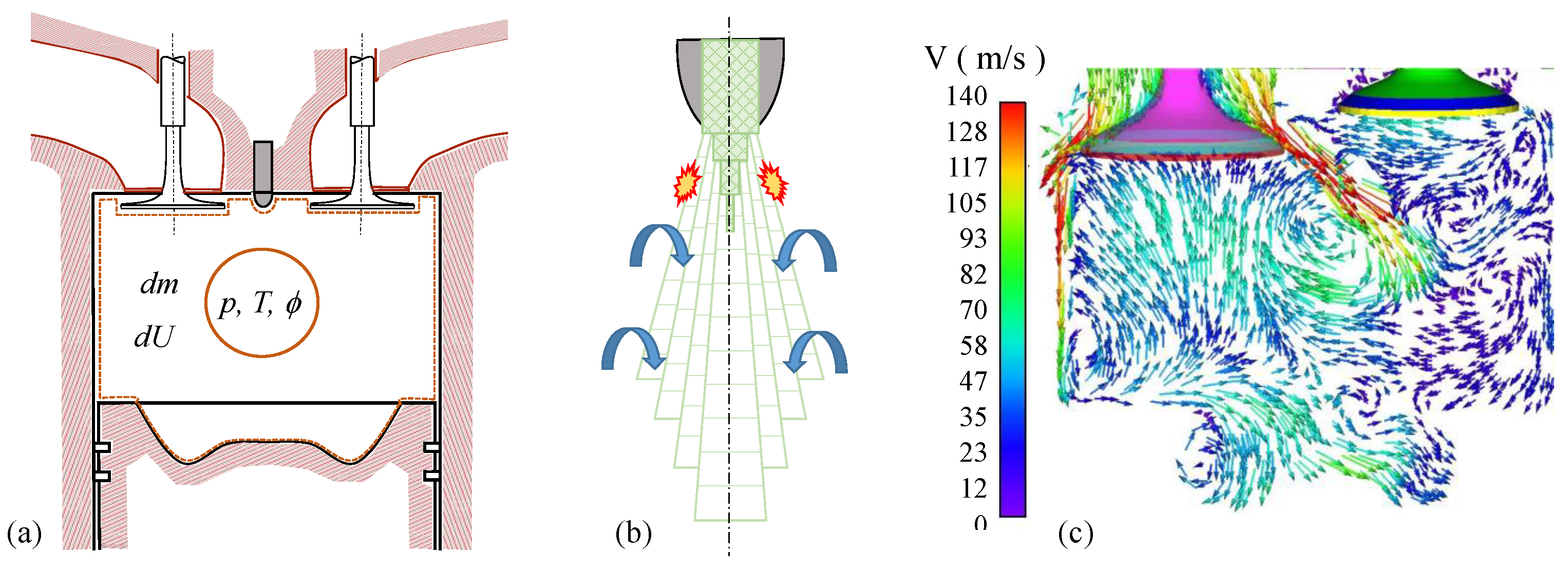
Figure 1. Combustion modeling. (a) Zero-dimensional thermodynamic models, (b) Quasi-dimensional models, and (c) Computational fluid dynamics models with chemical reaction—CRFD (Adapted from [31], figure (c) from [32]).
Atmosphere 15 01224 g001
Figure 2. Python engine solution flowchart.
Atmosphere 15 01224 g002
Figure 3. Pressure and temperature evolution along eight engine operation cycles at 2500 rpm, fuel injected mass = 0.125 g, mixture M1 (see Table 4 and Table 5 for details).
Atmosphere 15 01224 g003
Figure 4. Predicted engine expansion power (per cylinder) for all the mixtures at all numerical operation conditions simulated in this work. (Fuel mass injected per cylinder, per cycle, see Table 5 for details).
Atmosphere 15 01224 g004
Figure 5. Emissions: (a) CO, (b) CO2, (c) CH4 and (d) NOx—Engine at 2000 rpm (Fuel mass injected per cylinder, per cycle, see Table 5 for details).
Atmosphere 15 01224 g005
Figure 6. Emissions: (a) Soot precursors—PAH, (b) Soot particles with diameter: 2 nm < d < 10 nm, (c) Soot aggregates with collision diameter: 13 nm < dc < 250 nm—Engine at 2000 rpm (Fuel mass injected per cylinder, per cycle, see Table 5 for details).
Atmosphere 15 01224 g006
Figure 7. Emissions: (a) Nonmethane hydrocarbons, (b) unburned hydrocarbons, engine at 2000 rpm (Fuel mass injected per cylinder, per cycle, see Table 5 for details).
Atmosphere 15 01224 g007
Figure 8. Relative emission to M1 mixture: (a) Soot particles with diameter: 2 nm < d < 10 nm, (b) Total NOx, engine at 2000 rpm (Fuel mass injected per cylinder, per cycle, see Table 5 for details).
Atmosphere 15 01224 g008
Figure 9. Relative emission to M1 mixture: (a) CO, (b) CO2, (c) CH4, (d) NOx, (e) Soot precursors—PAH, (f) Soot particles, (g) Soot aggregates, (h) Non-methane hydrocarbons, (i) Total hydrocarbons—Engine at 1000 rpm (Fuel mass injected per cylinder, per cycle, see Table 5 for details).
Atmosphere 15 01224 g009
Figure 10. Relative emission to M1 mixture: (a) CO, (b) CO2, (c) CH4, (d) NOx, (e) PAH, (f) Soot particles, (g) Soot aggregates, (h) Non-methane hydrocarbons, (i) Total hydrocarbons—Engine at 2000 rpm (Fuel mass injected per cylinder, per cycle, see Table 5 for details).
Atmosphere 15 01224 g010
Figure 11. Relative emission to M1 mixture: (a) CO, (b) CO2, (c) CH4, (d) NOx, (e) PAH, (f) Soot particles, (g) Soot aggregates, (h) Non-methane hydrocarbons, (i) Total hydrocarbons—Engine at 3000 rpm (Fuel mass injected per cylinder, per cycle, see Table 5 for details).
Atmosphere 15 01224 g011
Table 1. Selected examples of fossil diesel surrogates blends reported in the literature.
Blends of SurrogatesYear-Ref.
70% n-decane/30% 1-methylnaphthalene(2010)-[41]
27.8% n-hexadecane/36.3% i-cetane/14.8% trans-decalin/(2016)-[29]
21.1% 1-methylnapthalene
23.5% n-octadecane/27.0% i-cetane/12.5% 1,2,4-trimethylbenzene/
20.9% tetralin/16.1% 1-methylnapthalene
2.7% n-hexadecane/20.2% n-octadecane/29.2% i-cetane/
5.1% n-butylcyclohexane/5.5% trans-decalin/7.5% 1,2,4-trimethylbenzene
15.4% tetralin/14.4% 1-methylnapthalene
10.8% n-octadecane/13.9% 1-methylnapthalene/7.3% 2-methylheptadecane/
19.1% n-butylcyclohexane/11.0% 1,3,5-triisopropylcyclohexane/16.4% tetralin
6.0% perhydrophenanthrene/14.7% 1,3,5-triisopropylbenzene/0.8% n-eicosane
100% n-dodecane(2017)-[40]
63.1% n-decane/36.9% 1-methylnaphthalene(2017)-[44]
85% n-heptane/15% toluene(2017)-[42]
81% n-heptane/14% toluene/5% cyclohexane
80% n-heptane/20% toluene
81% n-dodecane/14% toluene/5% cyclohexane
41.3% n-hexadecane/36.8% i-cetane/21.9% 1-methylnaphthalene(2018)-[45]
21.6% n-hexadecane/15.5% n-octadecane/26.0% i-cetane/
20.7% 1-methylnaphthalene/16.2% decalin
21.5% n-hexadecane/15.4% n-octadecane/25.8% i-cetane/
13.7% 1-methylnaphthalene/8.1% trans-decalin/8.1% n-butylbenzene/
7.4% n-butylcyclohexane
41.3% n-cetane/36.8% i-cetane/21.9% 1-methylnaphthalene(2019)-[46]
41.3% n-hexadecane/36.8% i-cetane/21.9% 1-methylnaphthalene(2020)-[47]
8.6% n-hexadecane/52% i-cetane/15.7% 1-methylnaphtalene/23.6%n-eicosane(2021)-[22]
7.2% 1-methylnaphthalene/46.4% trans-decalin/30% i-cetane/16.4% n-eicosane(2023)-[43]
20.5% i-cetane/3.5% n-octadecane/3.47% n-eicosane(2023)-[23]
7.24% n-butylcyclohexane/17.7% 1-methylnaphthalene/13.9% tetralin
13.7% n-hexadecane/20% trans-decalin
11% n-hexadecane/2.8% n-octadecane/2.6% n-eicosane
26.1% 1-methylnaphthalene/6.7% tetralin/7.24% n-butylcyclohexane
17.8% trans-decalin/1.7% n-butylbenzene
Table 2. Selected examples of biodiesel surrogates blends reported in the literature.
Blends of SurrogatesYear-Ref.
B30: 49% n-decane/21% 1-methylnaphthalene/30% methyl-octanoate(2012)-[54]
B100: 100% methyl decanoate (MD, C11H22O2)(2014)-[15]
B100: 100% methyl laurate (MLA, C13H26O2)
B100: 100% methyl myristate (MM, C15H30O2)
B100: 50% n-decane/50% methyl-octanoate(2015)-[51]
B100: 41.18% n-decane/9.41% methyl decenoate/49.41% methyl 5-decenoate(2015)-[55]
Soybean biodiesel: 62.9% methyl decanoate/15.0% n-hexadecane/(2019)-[56]
9.4% methyl trans-3-hexenoate/12.7% 1,4-hexadiene
B5: 11.44% 1-methylnaphtalene/58.39% i-cetane/30.16% n-eicosane(2021)-[22]
B10: 16.24% 1-methylnaphtalene/54.22% i-cetane/29.52% n-eicosane
B20: 17.93% 1-methylnaphtalene/51.15% i-cetane/30.90% n-eicosane
B50: 17.02% 1-methylnaphtalene/54.93% i-cetane/28.04% n-eicosane
B80: 35.28% 1-methylnaphtalene/38.85% i-cetane/25.85% n-eicosane
B100: 56.83% 1-methylnaphtalene/33.25% i-cetane/30.08% n-eicosane
B100: 50% methyl decanoate/40% n-heptane/(2022)-[50]
9% methyl crotonate/1% ethanol
B100: 100% methyl decanoate(2022)-[57]
B100: 47.5% methyl palmitate/4.5% methyl stearate/(2022)-[58]
39.6% methyl oleate/8.4% methyl linoleate
B25: 25% methyl butyrate/75% fossil diesel(2022)-[52]
B25: 25% methyl crotonate/75% fossil diesel
B100: 100% methyl isobutanoate(2022)-[59]
B100: 35.68% methyl butanoate/64.32% n-dodecane(2023)-[53]
B100: 100% methyl butanoate (MB, C5H10O2)
B100: 100% ethyl propionate (EP, C5H10O2)(2023)-[49]
B100: 100% methyl crotonate (MC, C5H8O2)
B100: 100% methyl decanoate (MDN, C11H10O2)
B100: 100% n-dodecane (DDC, C12H26)
Table 3. Reported works involving HVO in the literature.
Blends of SurrogatesYear-Ref.
57% n-tetradecane/24% n-hexadecane/9% i-cetane(2023)-[18]
22% n-dodecane/55% n-hexadecane/23% i-cetane
16% n-decano/61% n-hexadecane/23% i-cetane
8% n-heptane/67% n-hexadecane/25% i-cetane
70% n-hexadecane/19% i-cetane/11% cyclohexane
69% n-hexadecane/17% i-cetane/14% methyl-cyclohexane
70% n-hexadecane/30% i-cetane
Mix # 1: 81% i-cetane/19% 2-methyl-pentadecane(2020)-[64]
Mix # 2: 68% i-cetane/16% 2-methyl-pentadecane/16% 2-methyl-heptane
Mix # 3: 9% n-pentadecane/75% i-cetane/16% 2-methyl-pentadecane
Mix # 1: 9.3% n-pentadecane/13.8% n-hexadecane/26.5% n-heptadecane/(2013)-[21]
19.3% n-octadecane/31.1% i-dodecane
Mix # 2: 9.8% n-pentadecane/14.9% n-hexadecane/27.3% n-heptadecane/
20.7% n-octadecane/27.2% 2-methyl nonane
Mix # 3: 12.2% n-pentadecane/18.2% n-hexadecane/34.7% n-heptadecane/
and 26.3% n-octadecane/8.6% 2-methyl octane
Mix # 4: 13.13% n-pentadecane/19.54% n-hexadecane/37.70% n-heptadecane/
and 27.40% n-octadecane/.23% i-octane
Mix # 5: 13.17% n-pentadecane/19.59% n-hexadecane/37.81% n-heptadecane/
and 27.49% n-octadecane/1.94% i-octane
Table 4. Chemical species used as surrogates for numerical engine simulations in this work.
SurrogateFormulaReal Fuel
Diesel ASoybean DieselHVO
cyclohexaneC6H12
tolueneC6H5CH3
n-dodecaneC12H26
n-hexadecane (n-cetane)C16H34
i-cetane (2,2,4,4,6,8,8-heptamethylnonane)C16H34
methyl-decanoateC11H22O2
methyl-palmitateC17H34O2
methyl-linoleateC19H34O2
Table 5. Simulation parameters and conditions.
ParameterDescriptionValue
Engine speed and geometric
# disp_vol [m*3]Displaced volume0.00075
# comp_ratio [-]Compression ratio17.5
# piston_diam [cm]Piston diameter9.58
# rpmEngine speed1000–3000 ( Δ = 250)
Power boosting system
# turbo_T [K]Air temperature (after turbo/intercooler)300
# turbo_p [Pa]Boost pressure1.35 × 10 5
Fuel injection system
# T_injector [K]Fuel temperature at injector300
# p_injector [Pa]Fuel injection pressure1.80 × 10 8
# comp_fuelFuel composition (surrogates)Mixtures M1, M2 and M3
# injector_mass [kg]Fuel injected mass (per cylinder, per cycle)(12.5–37.5) × 10 5
Δ = 2.5 × 10 5
# perc_injector_pre [%]Fuel mass percentage at first injection stage7
# perc_injector_post [%]Fuel mass percentage at last injection stage0
# injector_pre_open [CA]SOI (at first injection stage)340
# injector_pre_close [CA]EOI (at first injection stage)348
# injector_main_open [CA]SOI (at main injection stage)350
# injector_main_close [CA]EOI (at main injection stage)365
# injector_post_open [CA]SOI (at last injection stage)395
# injector_post_close [CA]EOI (at last injection stage)415
Room conditions
# T_room [K]Temperature3.00 × 10 2
# p_room [Pa]Pressure1.00 × 10 5
Valve timing
# inlet_open [CA] BTDCIVO18
# inlet_close [CA]IVC198
# outlet_open [CA]EVO522
# outlet_close [CA]EVC18
Kinetics model for combustion process
# reaction_mechanismKinetics and thermo databaseCRECK Modeling Group
# comp_airIntake air composition21% O2, 79% N2
Simulation controls
# atolAbsolute tolerance for solution values1.00 × 10 16
# rtolRelative tolerance for solution values1.00 × 10 12
# sim_n_revolutionsCycles simulated (for each run condition)12
# delta_T_max [K]Maximum increase on temperature5
Disclaimer/Publisher’s Note: The statements, opinions and data contained in all publications are solely those of the individual author(s) and contributor(s) and not of MDPI and/or the editor(s). MDPI and/or the editor(s) disclaim responsibility for any injury to people or property resulting from any ideas, methods, instructions or products referred to in the content.