Article

Determination of the Structural Characteristic of the Refractive Index of Optical Waves in the Atmospheric Boundary Layer with Remote Acoustic Sounding Facilities

by
Sergei L. Odintsov
*,
Vladimir A. Gladkikh
,
Andrei P. Kamardin
and
Irina V. Nevzorova
V.E. Zuev Institute of Atmospheric Optics, Siberian Branch, Russian Academy of Sciences, Tomsk 634055, Russia
*
Author to whom correspondence should be addressed.
Atmosphere 2019, 10(11), 711; https://doi.org/10.3390/atmos10110711
Submission received: 20 September 2019 / Revised: 1 November 2019 / Accepted: 7 November 2019 / Published: 14 November 2019
(This article belongs to the Special Issue Atmospheric Turbulence Measurements and Calibration)

Abstract

:
The structural characteristic of the refractive index of optical waves was calculated from experimental data on the microstructure of the temperature turbulence in the atmospheric boundary layer. The experimental data were obtained with an acoustic meteorological radar (sodar), ultrasonic anemometer–thermometer, and meteorological temperature profilometer. Estimates of the structural characteristics for different conditions in the atmospheric boundary layer are presented and were compared with model profiles.

1. Introduction

Serial devices providing continuous remote diagnostics of the atmospheric boundary layer (ABL) in order to monitor the turbulence influencing the propagation of optical radiation through the atmosphere are now lacking. The need for development, production, and application of such devices is being driven by urgent problems, such as the stable operation of optical communication channels in the randomly inhomogeneous atmosphere, correction of optical observations (including adaptive correction), and prediction of propagation of laser radiation of different power levels in the ABL.
The structural characteristic of the refractive index, C n 2 , is one of the main parameters characterizing the strength of optical turbulence in the atmosphere. It is the result of parameterization of the structure function of the refractive index of optical waves in air. In our studies, we have followed the terminology and approaches described in References [1,2,3,4], which formulated both the principles of the effect of turbulence on wave propagation in the turbulent atmosphere, and the indisputable need for correct consideration of the spatiotemporal variability of C n 2 in atmospheric optics. Since the refractive index of optical waves is related to the air temperature, the structural characteristic C n 2 is proportional to C T 2 , which is a result of parameterization of the corresponding structure function. It should be noted that C T 2 in the ABL, especially in the surface layer, is much easier to determine than C n 2 . Therefore, in many studies, the parameter C T 2 has been determined first and then used to calculate C n 2 .
There is a long history of studies on spatiotemporal variability of C n 2 ( C T 2 ) in the atmosphere, but this work remains urgent today. In the absence of a detailed literature review on this subject, we would like to note some recent publications dealing with the analysis of C n 2 and C T 2 , with an emphasis on those papers considering simultaneous estimates of C n 2 or C T 2 at several levels. It is clear that the most accurate results have been provided by tower studies with turbulence meters (usually ultrasonic meteorological stations) installed at different levels. These data are used as reference data both for the analysis of turbulence characteristics and comparison with other devices. As an example, we refer to References [5,6,7,8], which discussed the results of C T 2 calculations based on tower measurements. In recent years, small unmanned aerial systems have been actively used for ABL studies. These systems are capable of providing C T 2 estimates not only in the vertical direction, but also in the horizontal plane [7,8,9]. However, their data do not always agree with other data [7]. Radiosondes have also been applied to study optical turbulence, and their information forms the basis for the calculation of C n 2 ( C T 2 ) both in the ABL and in higher layers [10,11,12]. The vertical profiles of C n 2 can also be calculated from analysis of observations of both artificial and natural atmospheric and extra-atmospheric sources of optical radiation [13,14,15]. Scintillometers are widely employed for estimation of C n 2 at near-surface paths. In the case of slanted paths, they allow the determination of layer-averaged values of C n 2 , as well as calculation of their vertical profiles [7,16,17].
This short list of the methods used for the determination of vertical profiles of the structural characteristic C n 2 ( C T 2 ) is mentioned only to demonstrate the main approaches used to obtain the necessary information, rather than to analyze these methods and their results in detail. For more detailed information, see the literature reviews in the referenced papers. However, all the methods mentioned either fail to provide for the continuous monitoring of C n 2 ( C T 2 ) profiles in the ABL with the proper space and time resolution, or can be implemented only from unique stationary objects, such as high meteorological towers.
Methods and technical facilities for remote sensing of the ABL appear promising for the study of C n 2 ( C T 2 ) . In particular, laser-sensing technologies for C n 2 (see, for example, References [18,19]) able to efficiently solve the formulated problem with the proper methodical and instrumental implementation are currently under development. However, the methods and technical facilities of remote acoustic diagnostics of the ABL (acoustic meteorological radars—sodars) are currently the closest, in our opinion, to solving the problem of online monitoring of the height–time profiles of the structural characteristic C n 2 , because sodars can work continuously under severe atmospheric conditions, provide satisfactory space and time resolution of the monitored parameters, and are not expensive to produce or use. In particular, the atmospheric signals recorded by sodars are proportional to the variance of the air temperature, which determines the variance of the refractive index of optical waves. The results published in Reference [8,9,20,21,22,23] provide an example of the application of sodar for determination of C n 2 ( C T 2 ) in the ABL. This paper is devoted to the application of sodar for estimation of C n 2 .
The main goal of this paper was to demonstrate the capability of sodar to provide a satisfactory space and time resolution in estimations of C n 2 in the ABL. This capability will allow the detailed study and prediction of the microstructure of the C n 2 field in the future.

2. Experimental Section

2.1. Method for Determination of Structural Characteristics

The technique of remote acoustic sounding of the ABL can be briefly described as follows. A sodar antenna with a beam width Ω ( f ) (rad) launches a short acoustic pulse into the atmosphere with the duration τ (s) and the carrier frequency f (Hz). In the course of propagation, acoustic waves are scattered, particularly in the backward direction, and are recorded by the same antenna (monostatic sounding scheme). The amplitude of the acoustic signal scattered at height H is proportional to the intensity of the temperature pulsations at this height (more precisely, to the pulse scattering volume V ( H ,   τ ,   Ω ) ). In the case of a vertically oriented sounding channel, the power P r ( H ,   f ) of the acoustic signal recorded from this height can be generally determined using the following equation (see, for example, References [1,23]),
P r ( H ,   f ) = P 0 ( f ) J ( f ) F ( f ,     H ,   M ,   V ) L a ( f ,   H ,   M ) L s ( f ,   H ,   Ω ,   M ,   M t ) C T 2 ( H )
where P 0 ( f ) is the power of the launched acoustic signal, J ( f ) is the instrumental function of the transceiving channel, F ( f ,   M ,   V ,   H ) is the function associated with the conditions of propagation of the sounding signal in the atmosphere, and L a ( f ,   H ,   M ) and L s ( f ,   H ,   Ω ,   M ,   M t ) are the factors responsible for the signal attenuation at the sounding path due to absorption and scattering, respectively. The influences of the average values of the meteorological parameters (temperature and humidity of air, atmospheric pressure, and wind velocity) on the sound propagation and the pulsation characteristics are denoted as M and M t , respectively. Both M and M t depend on the height H . It should be noted that the power of the received signal P r ( H ,   f ) is assumed to depend only on the height and the carrier frequency of the sounding pulse, although it actually depends on the full set of variables on the right-hand side of Equation (1). It should be emphasized that C T 2 ( H ) should remain the same regardless of the sounding frequency f .
Equation (1) includes the simplified relationship of the acoustic signal recorded from the atmosphere to the structural characteristic of the air temperature C T 2 ( H ) . For a detailed description of the relationship between P r ( H ,   f ) and C T 2 ( H ) , see Reference [1]. However, most existing techniques for interpreting the results of acoustic sounding of the atmosphere employ equations similar to Equation (1) (see References [9,21,23]). We also used Equation (1) as a basis, and wrote the equation for calculation of C T 2 ( H ) as follows [24,25,26]:
C T 2 ( H ) = B r ( f )     τ   f 1 / 3 T ( H ) 5 / 3   H 2 L ( H , f ) 1   A c , r 2 ( H , f ) = B r ( f )   G ( H , f ) A c , r 2 ( H , f ) ,   ( K 2 / m 2 / 3 )
where G ( H , f ) = τ   f 1 / 3 T ( H ) 5 / 3   H 2 L ( H , f ) 1 , T is the temperature of air (in K), B r is the calibration coefficient related to both the output power and the characteristics of the transceiving channel of the sodar antenna (only the frequency dependence is shown), and A c , r is the pressure amplitude (Pa) of the useful signal from height H at the frequency f and the sounding pulse duration τ . It should be noted that at time t , when the signal from height H is recorded, the useful signal A c , r measured by the sodar is combined with the noise component A n : A r ( H ) = A c , r ( H ) + A n ( H ) . Here, the height dependence of the noise component A n has a formal character, emphasizing only that it corresponds to the time at which the signal from height H is received. In turn, L ( H ) = L a L s exp { 2 H [ α b ( f ,   M ) + α s ( f ,   Ω ,   M ,   M t ) ] } , where the functions α b ( f ,   M ) and α s ( f ,   Ω ,   M ,   M t ) are associated with the sound attenuation due to absorption and scattering (loss of the sound energy by the sounding beam), respectively.
To apply Equation (2), it is necessary both to separate the component A c , r from the signal + noise mixture recorded by the sodar and to correctly estimate the influence of the function α s ( f ,   Ω ,   M ,   M t ) . This is not a trivial task. While we have not provided a detailed description of the procedure, we would like to note that for separation of the useful signal A c , r , we used the combined analysis algorithms of the signal-to-noise ratio and the Doppler shift statistics, which were used to find the radial (along the sounding path) components of the wind velocity. The estimates of the function α s ( f ,   Ω ,   M ,   M t ) were based on consideration of the wind dispersion values measured by the sodar and the size of the antenna’s directional pattern at different heights (measured previously).
It should be noted that Equation (2) corresponds to the vertical orientation of the sodar measuring channel. However, slanted sounding channels can also be used for estimation of C T 2 ( H ) ; in such a case, Equation (2) should be modified.
One of the main steps in calculation of the profiles of the absolute values of C T 2 using Equation (2) is the correct setting of the calibration coefficient B r , which depends on both the design features of the particular sodar antenna and the carrier frequency of the sounding signal. One of two approaches is generally used for this step. The first approach is based on the instrumental calibration of the measuring channels. In this case, transmitted and recorded signals with known amplitude–frequency characteristics are thoroughly measured. This is a rather laborious process, requiring some important conditions to be fulfilled in the experiments. Examples of this calibration method can be found in Reference [27,28]. However, another approach is more widely used; it is based on referencing the vertical profiles C T , n 2 ( H ) obtained by a sodar and measured in arbitrary units to absolute values of C T 2 ( H ) measured by independent devices (for example, by ultrasonic anemometers–thermometers or aerial systems). This allows the calibration coefficient B r ( f ) to be determined (calculated). The results reported below were obtained by applying the second approach, using measurements of the turbulence in the surface layer recorded by ultrasonic anemometers–thermometers [24,25]. This technique was also used, for example, in References [21,22].
As a result, the reported results obtained by applying Equation (2) are only estimations and cannot be considered to be measured, because they were obtained based on significant assumptions. Nevertheless, Equation (2) allows, in our opinion, an objective judgement of the height–time variability of C T 2 and C n 2 ( C T 2 ) .
The structural characteristic of the refractive index of the optical waves was calculated using Equation (3).
C n 2 ( H , λ ) = ( 1 + 0.00752 λ 2 ) 2 [ 77.6 p ( H ) T 2 ( H ) 10 6 ] 2 C T 2 ( H ) ,   ( m 2 / 3 )
where λ is the optical wavelength (µm) and p is the atmospheric pressure (hPa). The atmospheric pressure profile was determined using the standard barometric formula with the measured air temperature profile [29]. It was assumed in the calculation of C n 2 ( H ,   λ ) that the optical radiation fell within the infrared spectral range. Therefore, the factor outside the square on in the right-hand side of Equation (3) was assumed to be equal to unity. For short-wavelength radiation, the values of C n 2 ( H ,   λ ) can be estimated by simple multiplication of the C n 2 ( H ) profiles by the corresponding factor.

2.2. Instrumentation and Measurement Site

The experimental data for calculation of the C n 2 ( H ) profiles were obtained from the Volna-4M three-channel sodar [30]. The sodar was installed on the roof of the laboratory building of the V.E. Zuev Institute of Atmospheric Optics SB RAS (Akademgorodok, Tomsk). It provided measurements in the height range 45–700 m, with a vertical step of 5 m and a time step of about 7 s. The measurements were carried out at 08:00–21:00 local time. The observation site was surrounded by one- to seven-floor buildings and forest plantations up to 20 m high. Thus, this site can be classified as an urban territory. The sodar operated in the mode of simultaneous transmission of pulsed sounding acoustic signals from three antennas. Each antenna transmitted a 0.15 s pulse at the given carrier frequency (frequencies of 1900, 2100, and 2300 Hz were used). In the next launch of the sounding pulse from a given antenna, the carrier frequency changed; the carrier frequency in a series of sounding pulses was cyclically alternated. The three antennas transmitted pulses with different carrier frequencies simultaneously. This sodar operation regime results in a better quality C T 2 estimation due to the more flexible algorithm for the separation of useful signals A c , r against the background. In addition, since one antenna was oriented vertically and the other two had a small tilt (zenith angle of 20°), the atmospheric boundary layer zones covered by these antennas lay side by side. This allowed us to expect that the nine vertical profiles C T 2 ( H ) obtained by the different antennas at different frequencies would coincide after averaging for the rather long time period (for example, several tens of minutes), provided that the calibration coefficients B r ( f ) had been determined correctly.
Since the parameters of the signals received by the sodar (amplitude, Doppler shift) are influenced by the random fields of the air temperature and wind velocity components, the statistical analysis of A c , r was used to estimate the sought parameters. One (instantaneous) C T 2 ( H ) was usually calculated for a time interval of 10 min.
Meteorological parameters were measured simultaneously at the same site (round the clock) by the Meteo-2 ultrasonic meteorological station (UMS) [31] (at a height of 5 m from the roof and 17 m from the surface). In addition, air temperature profiles were measured by the MTP-5 profilometer [32] in the height range 17–1000 m, with a time step of 5 min and a vertical step of 50 m. The results obtained by the Meteo-2 UMS were used to determine the calibration coefficients B r ( f ) . The MTP-5 results were used to calculate the C n 2 ( H ) and G ( H , f ) functions entered into Equation (2).

2.3. Method for Fitting Calibration Coefficients

The fitting of the calibration coefficients B r ( f ) and verification of the calculated C T 2 ( H ) profiles were carried out via comparison with the model C T , m 2 ( H ) profiles characteristic of the convective conditions. For this procedure, the days with pronounced convection observed in the ABL in the of 11:00–17:00 LT period were selected from sodar echograms. Examples of these echograms are shown in Figure 1. The figure shows initial echograms of the vertically oriented sounding channel without rejection of the noise components. The carrier frequency of the sounding pulses was 2100 Hz. The degree of blackening at the low levels of the echograms corresponds to the amplitude A c , r (mixed with noise). The general grey background in the echograms characterizes the noise intensity of the sodar signals (noise component A n ). The high degree of intermittence of the zones with the high intensity of temperature pulsations in the ABL is noteworthy (the stronger the pulsations, the more intense the blackening in the echograms). It should be also noted that since the measurements were carried out over an urban territory in the daytime, the background noise intensity did not allow us to record signals from higher levels than those seen in the echograms (usually no higher than 400–500 m).
In fitting the calibration coefficients B r ( f ) , it was assumed that on the chosen days, the C T 2 ( H ) profiles the ABL convection could be described by Equation (4).
C T , m 2 ( H ) = C T 2 ( H c ) { ( H / H c ) 2 / 3 ,   H H c ( H / H c ) 4 / 3 ,   H > H c
where the height H c corresponds to the level above which the profile C T 2 ( H ) changes its shape. This model is based on empirical data (see, for example, Reference [4]). It was in agreement with our earlier experimental studies of normalized C T 2 ( H ) profiles at the given observation site [26]. According to Reference [26], H c falls within the range 60–80 m. In Reference [4], the level H c 30 m was reported as judged from measurements taken in a steppe region. Equation (4) corresponds to the averaged (for a rather long time period) profile of the structural characteristic C T 2 ( H ) .
To determine B r ( f ) , we assumed that at a height H d   H c , from which the sodar was able to receive signals, Equation (5) would be valid (overbar denotes time averaging).
C T , m 2 ( H d ) = C T 2 ( H d ) ¯ = B r ( f )   G ( H d , f ) A c , r 2 ( H d , f ) ¯
that is, the average value of the structure characteristic C T 2 measured by the sodar at the height H d is equal to the model value calculated as
C T , m 2 ( H d ) = C T , s 2 ( H 0 ) ¯ ( H d / H 0 ) 2 / 3
where C T , s 2 ( H 0 ) is determined from the results obtained by the ultrasonic meteorological station installed at height H 0 (see, for example, References [33,34]).
From Equations (5) and (6), we wrote the equation for estimation of the calibration coefficient B r ( f ) as
B r ( f )   = C T , s 2 ( H 0 ) ¯ ( H d / H 0 ) 2 / 3   /   G ( H d , f ) A c , r 2 ( H d , f ) ¯
The right-hand side of this equation includes only the parameters known from the measurements, namely C T , s 2 ( H 0 = 5   M ) and A c , r ( H d , f ) , as well as the calculated values of G ( H d , f ) . As a result, using the experimental dataset (under convection conditions) and assuming H = d 75 m, we obtained the set of calibration coefficients B r ( f ) , remembering that that the coefficients B r ( f ) are unique for every sodar antenna and every acoustic frequency used for the sounding. We also used this approach to determine B r ( f ) in our earlier words [24,25]. The results obtained imply the necessity of periodic refinement of the calibration coefficients for all sodar measuring channels and all frequencies used.

3. Results and Discussion

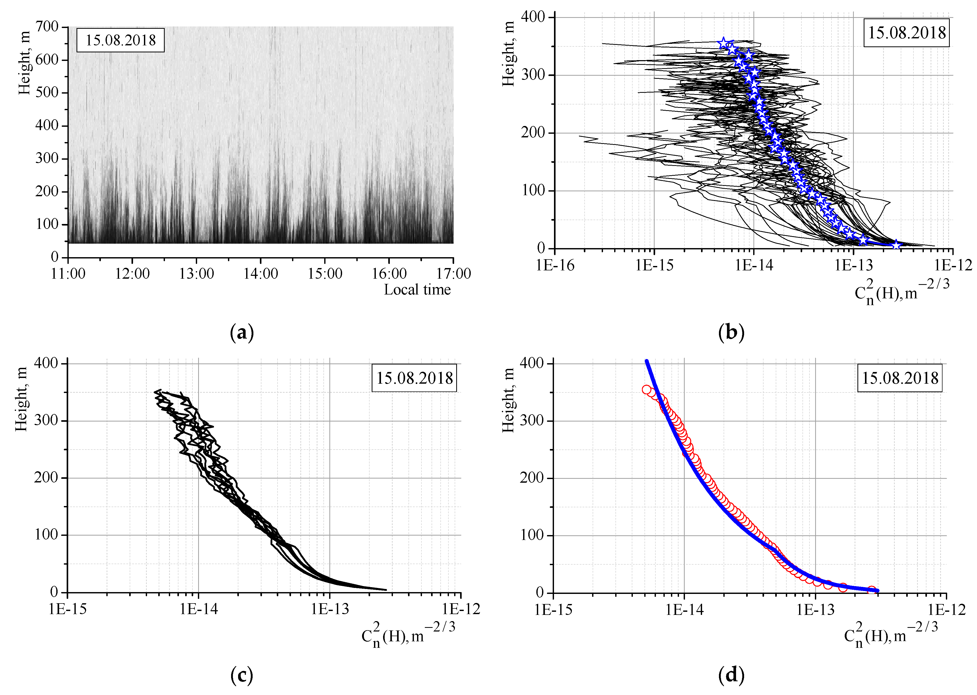
Let us exemplify the calculation of the profiles C n 2 ( H ) using Equation (3) with the use of the estimates of C T 2 ( H ) made by Equation (2) on one of the days chosen for analysis—15 August 2018, 11:00–17:00 local time. Figure 2a shows the initial echogram obtained at the frequency of 2300 Hz by one of the slanted sodar channels. Figure 2b depicts the plots of the current C n 2 ( H ) profiles corresponding to the echogram shown in Figure 2a and calculated for time intervals of 10 min (36 profiles). The measurement time is not shown, because this figure serves only to illustrate the general pattern of variation of the C n 2 ( H ) profiles for the measurement period. The same figure also shows the plot (asterisks) of the average C n 2 ( H ) profile for this period. It should be taken into account that the current C n 2 ( H ) profiles between the levels of 5 m and 75 m were calculated using the power law C n 2 ( H ) H m , with the exponent m dependent on the measured values of C n 2 at heights of 5 m (with the sonic) and 75 m (with the sodar). The technique used and details of the algorithm can be found in Reference [24].
Figure 2c shows nine C n 2 ( H ) profiles averaged for the period 11:00–17:00 LT for all the channels and at all the frequencies (omitted), and Figure 2d shows the average profile (symbols) and model profile (solid curve) calculated by Equation (4) with reference to the average profile at the height H = c 75 m. The variation of the current C n 2 ( H ) profiles across all measurement channels and at all frequencies approximately coincided with that demonstrated in Figure 2b.
The example shown in Figure 2 allowed us to state that the use of sodar findings was able to adequately estimate vertical profiles of the structural characteristic C n 2 ( H ) . Without additional illustrations, we also noted that on other days with pronounced convection, the average (over all measurement channels and frequencies) C n 2 ( H ) profiles calculated from the sodar data were close in shape to Equation (4). It was clear that we should not expect the experimental C n 2 ( H ) profiles to be identical to those of the model.
In summary, we concluded that careful fitting of the calibration coefficients B r ( f ) and the efficient separation of useful sodar signals A c , r ( H , f , t ) enabled the calculation of instantaneous C n 2 ( H ) profiles with satisfactory quality. In this case, the calibration coefficients were correct not only for convective conditions, but also for all other measurement periods.
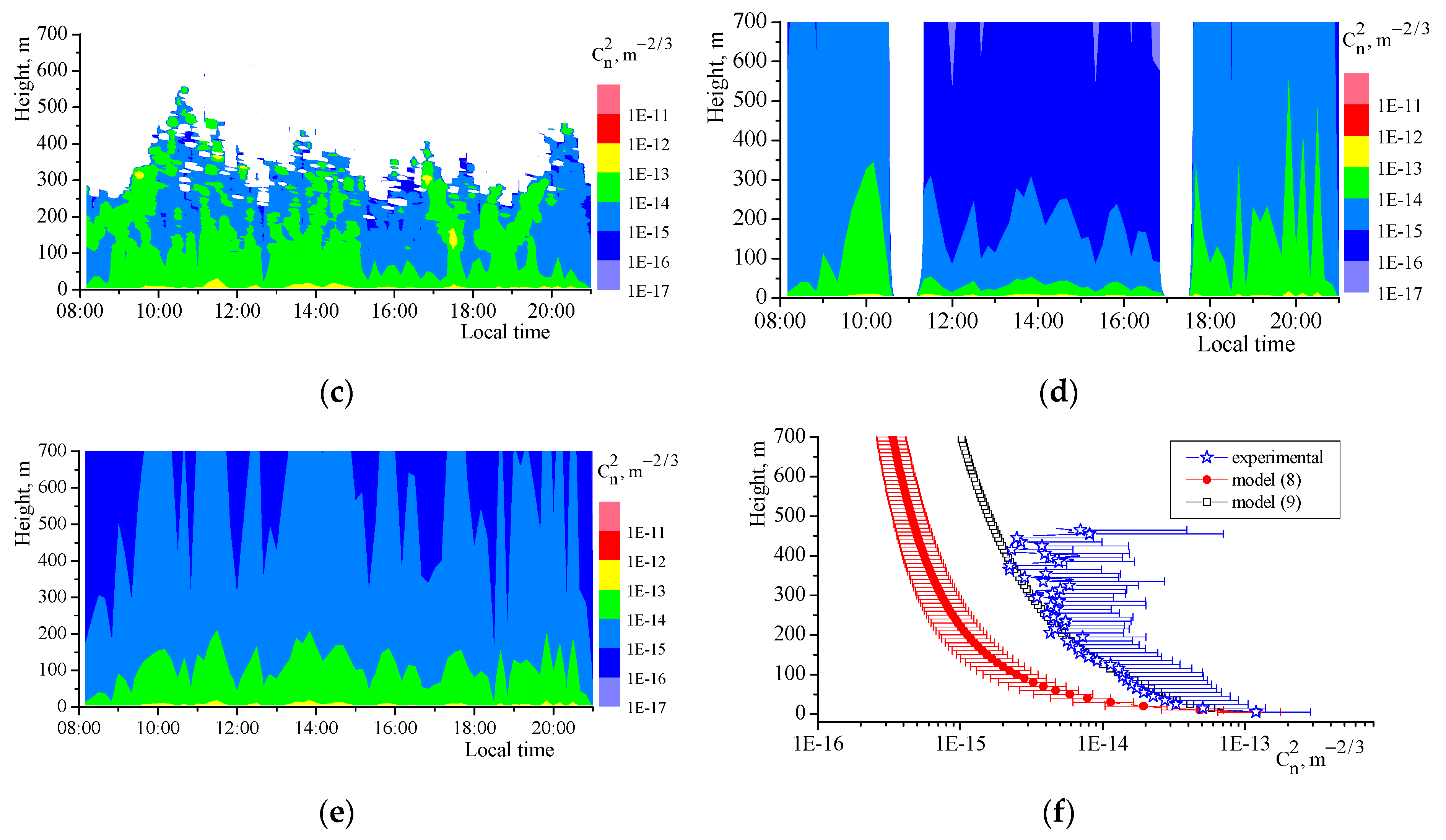
We now present examples of calculated height–time C n 2 ( H , t ) profiles not only for daytime convection conditions, but also for other types of temperature stratification. Figure 3a shows the initial echogram of the vertically oriented sounding channel for the carrier frequency of 2100 Hz, measured on 9 June 2019 between 08:00 and 21:00 LT. This period was chosen because air temperature inversion was observed at the start and the end of the episode, and convection occurred at midday (Figure 3b). The C n 2 ( H , t ) field calculated from the experimental data is shown in Figure 3c. It should be noted that the background noise intensity allowed the sodar to receive signals from 400–500 m only. Therefore, the distribution of C n 2 ( H , t ) had a pronounced top, being limited to values in the order of   10 15 m−2/3.
Previous publications analyzing the distribution of C n 2 in the atmosphere, including in the boundary layer, have presented some model equations. For comparison, we used the model published in References [17,35]. According to this model,
C n 2 ( H , t ) = K 2.7 10 16 exp ( H / 1500 ) + C n , s 2 ( H 0 , t ) ( H / H 0 ) p
where the exponent p is equal to −2/3 in the case of stable stratification and −4/3 for convective conditions. Equation (8) is a somewhat truncated version of the initial equation [17,35], because it was used only for the atmospheric boundary layer. The calculations were carried out at K = 1 . The value of C n , s 2 ( H 0 ) was the structural characteristic calculated from the findings of the ultrasonic meteorological station ( H 0 = 5 m).
Figure 3d shows the results of the calculation using Equation (8), with the intervals of stable and unstable stratification separated by gaps. This separation was based on the temperature profiles shown in Figure 3b. Comparing the experimental data (Figure 3c) with the model data (Figure 3d), we found a discrepancy between them, especially in daytime. This was attributed, in particular, to the fact that the model profile from Equation (8) was smooth from the lowest level ( H 0 ). However, as was already mentioned, the C n 2 ( H ) profile may have had a break in the height range 60–80 m at the observation site under convection conditions. In this case, the model has the form
C n 2 ( H , t ) = C n , s 2 ( H 0 , t ) ( H H 0 ) 2 / 3 ,     H     H d , C n 2 ( H , t ) = C n 2 ( H d , t ) ( H H d ) 4 / 3 ,       H   >   H d .
where H d is the height of profile “breakage”. It is obvious that a fixed value of H d was not physically justified. This value varied both within and between observation days. We did not study regularities of H d variations in this work. When processing the results of measurements from 9 June 2019, we used the value H d = 75 m and calculated the model distribution C n 2 ( H , t ) using Equation (9); it is shown in Figure 3e. According to this figure, the model values calculated by Equation (9) for the daytime were in somewhat closer agreement with the actual values in comparison to the calculations by Equation (8) (Figure 3d). Figure 3f compares the averaged experimental C n 2 profiles for the 11:00–17:00 LT period with the model ones. The averaged profile calculated by Equation (8) is plotted with standard deviations. The averaged C n 2 profile calculated by Equation (9) was characterized by approximately the same spread in values. It should be noted that the plot of the averaged experimental C n 2 profiles corresponded to the median values, since at levels above approximately 350 m, the statistical provision of the estimates was poor and, in our opinion, it was preferable to consider the median values rather than the sample averages. In this case, the spread of C n 2 values at each level was characterized by the third quartile ( Q 3 ) of the integral distribution function, shown here as half-bars near the experimental data. As a result, we concluded that the experimental data from the C n 2 ( H , t ) field in daytime were in good agreement with Equation (9). However, under conditions of stable stratification, neither Equation (8) nor (9) provided for an adequate presentation of the C n 2 ( H , t ) field (at least, at our observation site).
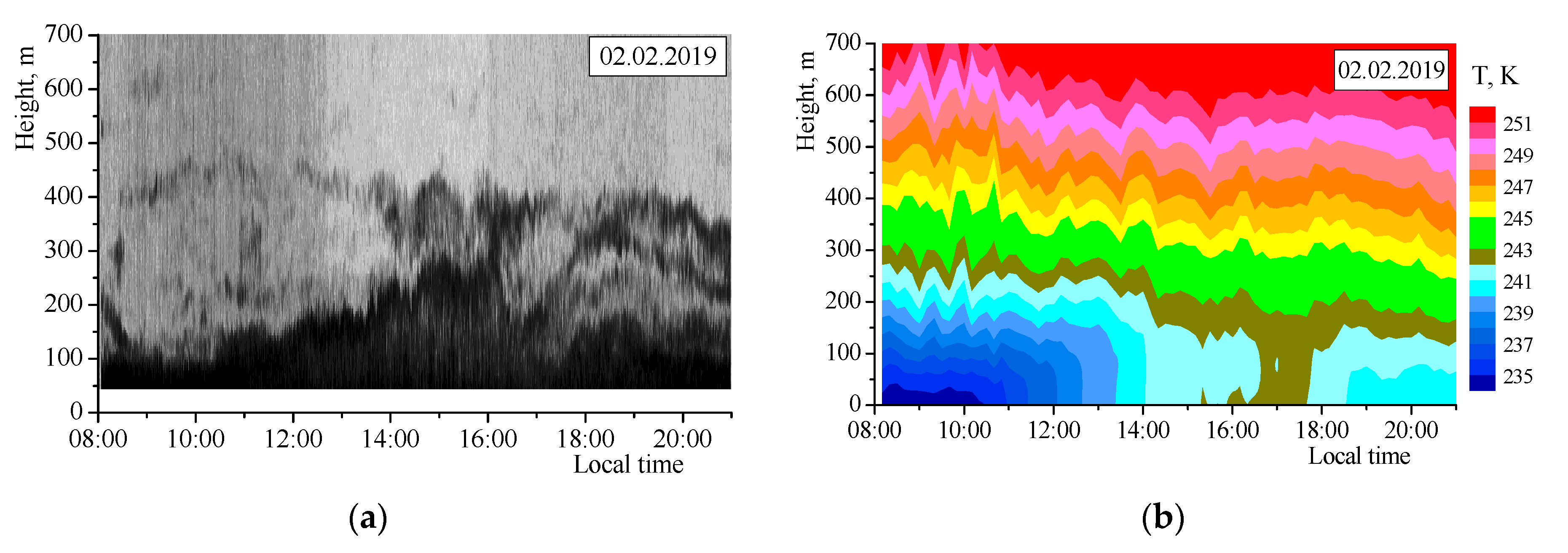
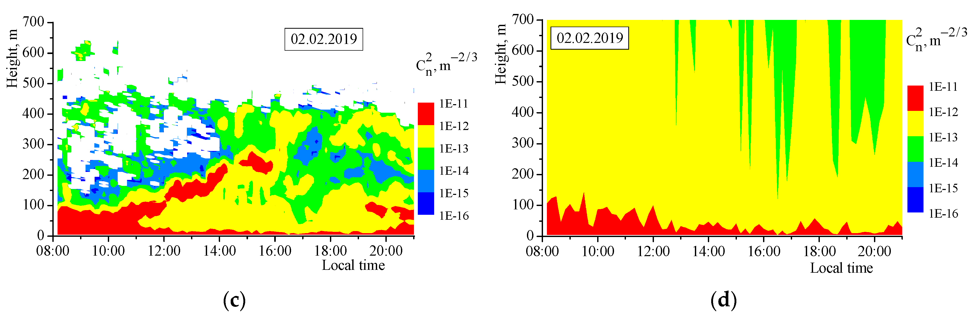
In conclusion, we present some examples demonstrating the efficiency of sodar application in the cases where no one existing model of the height–time distribution of C n 2 in the ABL was able to describe the actual field of this parameter. Of particular interest, in our opinion, are situations with large values of C n 2 in the ABL under conditions of strong temperature inversions. One such case is shown in Figure 4, corresponding to the winter season (2 February 2019). Figure 4a shows the initial echogram of the vertically oriented sounding channel, with the carrier frequency of 1900 Hz in the sounding pulse. The distribution of air temperature in the ABL in this period is shown in Figure 4b. A rather strong temperature inversion was observed in the ABL throughout the day. The temperature profile was close to isothermy in the layer below 200 m only in the period of approximately 16:30–17:40 LT. The height–time distribution of C n 2 for this day is shown in Figure 4c. According to this figure, even with the strong temperature inversion limiting the processes of turbulence generation and the turbulence lifetime, the values of C n 2 could be large, and not only in the near-surface layer. The results of C n 2 ( H , t ) calculation using Equation (8) with the exponent p = 2 / 3 (corresponding to stable stratification) are shown in Figure 4d. It is obvious that the height–time distribution of model C n 2 values differed widely from the experimental data shown in Figure 4c.
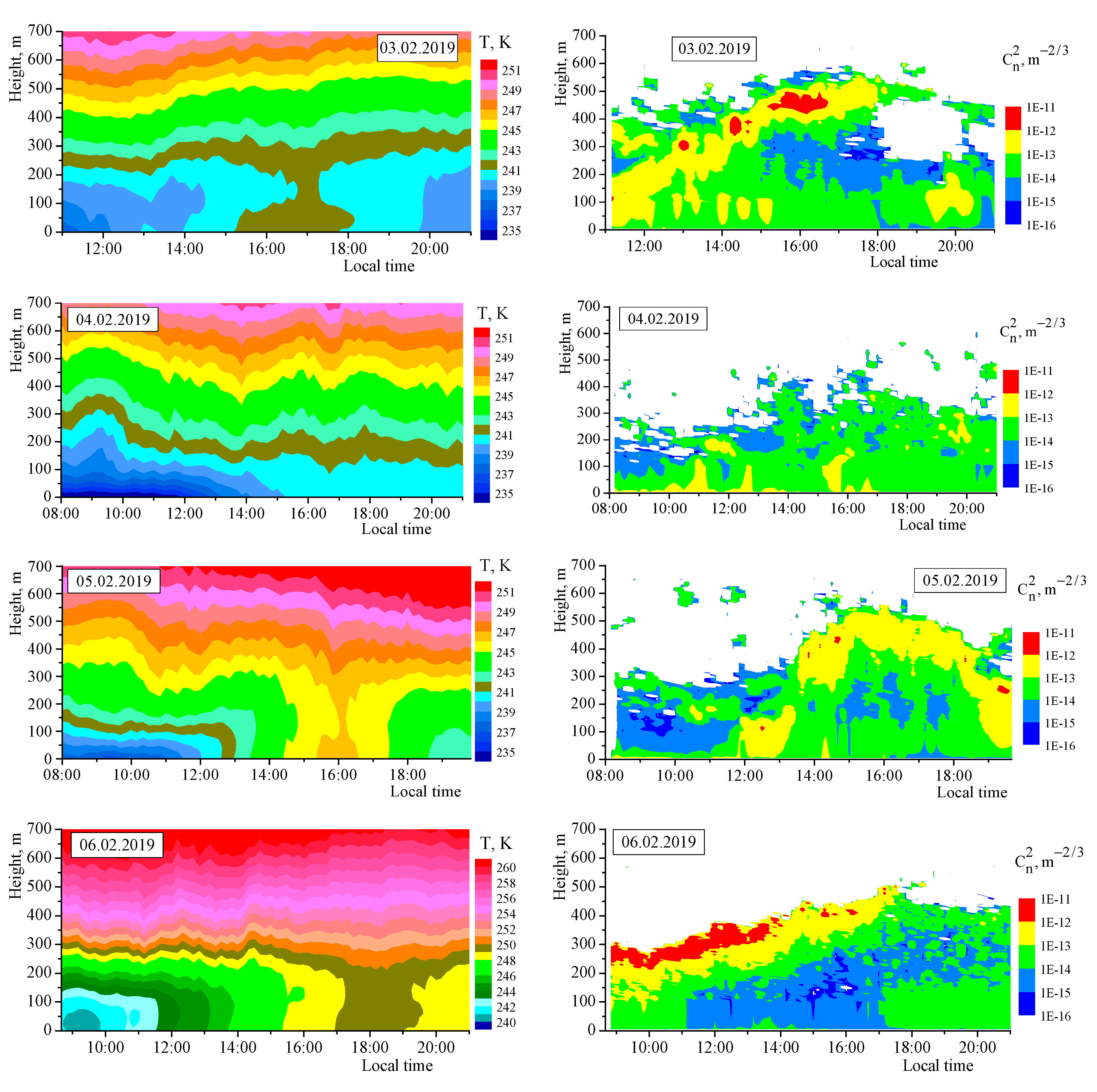
The results shown in Figure 4 are not unique. These situations occur quite often at the observation site, especially in the cold season [36]. This was confirmed by the data shown in Figure 5, which shows the height–time distributions of the air temperature in the ABL (left column) and the structural characteristic C n 2 (right column) in the five days following 2 February 2019. Similar episodes were also observed later.
It should be noted that the intensity of the ambient (acoustic) noise in the periods of observations did not allow the reliable recording of sodar signals corresponding to C n 2 < 10 16 m−2/3. At lower ambient noise, it might be possible to obtain estimates of C n 2 10 17 ÷ 10 18 m−2/3 and to achieve higher sounding levels, for example 1 ÷ 1.5 km.
Unfortunately, we were not able to compare the profiles of C T 2 ( H , t ) and C n 2 ( H , t ) calculated through acoustic sounding with other measures of these parameters. The reliability of the obtained estimates could be checked only through comparison with the existing models, and from the general physical laws governing the distribution of turbulence characteristics in the atmospheric boundary layer.

4. Conclusions

We drew the following conclusions. The methods and facilities of remote acoustic sounding were able to provide for calculation of the height–time distribution of the structural characteristic of air temperature C T 2 ( H , t ) in the atmospheric boundary layer and then, from this calculation, the structural characteristic of the refractive index of optical waves C n 2 ( H , t ) . The height resolution in the estimates of these characteristics could range from a few meters to several tens of meters depending on the sounding parameters (duration of the sounding pulse, carrier frequency, and so on). The time step of measurements of the C T 2 and C n 2 profiles was determined by the height range of sounding, requirements of statistical provision of the estimates, and the effects of ambient factors (for example, acoustic noise). For the sodar results reported in this paper, the minimal time step in the calculation of C T 2 and C n 2 was 2 min, although, because of the high noise, we considered the time step of 10 min to be optimal in this case.
It should be emphasized that the results reported in this paper are only estimates and cannot be considered measured data, because they were obtained with some significant assumptions made. Nevertheless, we believe that the described technique allows correct determination of the order of magnitude of the parameters under study, and objective judgement of the height–time variability of C T 2 and C n 2 in the atmospheric boundary layer. In particular, attention should be drawn to the peculiarities of the vertical profiles of these parameters under conditions of strong temperature inversions, when these profiles seldom obey the existing models for the case of stable stratification.
We have also highlighted the potential of sodar as auxiliary equipment for online operation of optical instruments (telescopes, different-purpose laser systems), because sodar is able to provide, under some conditions, real-time profiles of the structural characteristics C T 2 and/or C n 2 , as well as the wind vector in the atmospheric boundary layer.

Author Contributions

Conceptualization, S.L.O.; Formal analysis, S.A.O. and I.V.N.; Investigation, V.A.G. and A.P.K.; Project administration, S.L.O.; Resources, S.L.O.; Software, I.V.N.; Writing—Original draft, S.L.O.; Writing—Review & editing, S.L.O.

Funding

The measurement of atmospheric characteristics was supported by the Russian Science Foundation (Grant No. 19-71-20042). The development of techniques for determination of structure characteristics was supported by the Ministry of Science and Higher Education of the Russian Federation (Project No. AAAA-A17-117021310152-4).

Conflicts of Interest

The authors declare no conflicts of interest.

References

  1. Tatarski, V.I. Wave Propagation in a Turbulent Medium; McGraw-Hill: New York, NY, USA, 1961. [Google Scholar]
  2. Stroben, J.W. Laser Beam Propagation in the Atmosphere; Springer: Berlin, Germany, 1978. [Google Scholar]
  3. Zuev, V.E. Laser Beams in the Atmosphere; Springer: New York, NY, USA, 1982. [Google Scholar]
  4. Mironov, V.L. Laser Beam Propagation in the Turbulent Atmosphere; Nauka: Novosibirsk, Russia, 1981. (In Russian) [Google Scholar]
  5. Braam, M.; Moene, A.F.; Beyrich, F. Variability of the structure parameters of temperature and humidity observed in the atmospheric surface layer under unstable conditions. Bound. Layer Meteorol. 2014, 150, 399–422. [Google Scholar] [CrossRef]
  6. Braam, M.; Moene, A.F.; Beyrich, F.; Holstlag, A.A.M. Similarity relations for CT2 in the unstable atmospheric surface layer: Dependence on regression approach, observation height and stability range. Bound. Layer Meteorol. 2014, 153, 63–87. [Google Scholar] [CrossRef]
  7. Braam, M.; Beyrich, F.; Bange, J.; Platis, A.; Martin, S.; Maronga, B.; Moene, A.F. On the discrepancy in simultaneous observations of structure parameter of temperature using scintillometer and unmanned aircraft. Bound. Layer Meteorol. 2016, 158, 257–283. [Google Scholar] [CrossRef]
  8. Wainwright, C.E.; Bonin, T.A.; Chilson, P.B.; Gibbs, J.A.; Fedorovich, E.; Palmer, R.D. Methods for evaluating the temperature structure-function parameter using unmanned aerial systems and large-eddy simulation. Bound. Layer Meteorol. 2015, 155, 189–208. [Google Scholar] [CrossRef]
  9. Bonin, T.A.; Goines, D.C.; Scott, A.K.; Wainwright, C.E.; Gibbs, J.A.; Chilson, P.C. Measurements of the temperature structure-function parameters with a small unmanned aerial system compared with a sodar. Bound. Layer Meteorol. 2015, 155, 417–434. [Google Scholar] [CrossRef]
  10. Martini, E.; Freni, A.; Cuccoli, F.; Facheris, L. Derivation of clear-air turbulence parameters from high-resolution radiosonde data. J. Atmos. Ocean. Technol. 2017, 34, 277–293. [Google Scholar] [CrossRef]
  11. Vernin, J.; Trinquet, H.; Jumper, G.; Murphy, E.; Ratkovski, A. OHP02 gravity wave campaign in relation to optical turbulence. Environ. Fluid Mech. 2007, 7, 371–382. [Google Scholar] [CrossRef]
  12. Trinquet, H.; Vernin, J. A statistical model to forecast the profile of the index structure constant Cn2. Environ. Fluid Mech. 2007, 7, 397–407. [Google Scholar] [CrossRef]
  13. Nosov, V.V.; Lukin, V.P.; Nosov, E.V.; Torgaev, A.V. Method for atmospheric turbulence profile measurement from observation of laser guide stars. Atmos. Ocean. Opt. 2017, 30, 176–183. [Google Scholar] [CrossRef]
  14. Bal’basova, L.A.; Lukin, V.P. Adaptive Correction of Atmospheric Distortions of Optical Images Against an Artificial Guide Star; Fizmatlit: Moscow, Russia, 2012; p. 128. (In Russian) [Google Scholar]
  15. Ziad, A.; Chabe, J.; Fantei-Caujolle, Y.; Aristidi, E.; Renaud, C.; Rahhal, M.B. CATS: An autonomous station for atmospheric turbulence characterization. Proc. SPIE 2018, 10703, 107036L. [Google Scholar]
  16. Sprung, D.; Sucher, E.; Ramkilowan, A.; Griffith, D.J. Investigation of optical turbulence in the atmospheric surface layer using scintillometer measurements along a slant path and comparison to ultrasonic anemometer measurements. Proc. SPIE 2014, 9242, 92421I. [Google Scholar]
  17. Andrews, L.C.; Phillips, R.L.; Crabbs, R.; Wayne, D.; Leclerc, T.; Sauer, P. Creating a Cn2 profile as a function of altitude using scintillation measurements along a slant path. Proc. SPIE 2012, 8238, 82380F. [Google Scholar]
  18. Razenkov, I.A. Turbulent Lidar: I−Design. Atmos. Ocean. Opt. 2018, 31, 273–280. [Google Scholar] [CrossRef]
  19. Razenkov, I.A. Turbulent Lidar: II−Experiment. Atmos. Ocean. Opt. 2018, 31, 281–289. [Google Scholar] [CrossRef]
  20. Petenko, I.; Argentini, S.; Casasanta, G.; Genthon, C.; Kallistratova, M. Stable surface-based turbulent layer during the polar winter at Dome C, Antarctica: Sodar and in situ observations. Bound. Layer Meteorol. 2019, 171, 101–128. [Google Scholar] [CrossRef]
  21. Petenko, I.; Mastrantonio, G.; Viola, A.; Argentini, S.; Pietroni, I. Some statistics of the temperature structure parameter in the convective boundary layer observed by sodar. Bound. Layer Meteorol. 2014, 150, 215–233. [Google Scholar] [CrossRef]
  22. Travouillon, T.; Schöck, M.; Els, S.; Riddle, R.; Skidmore, W. Using sodar to measure optical turbulence and wind speed for the meter telescope site testing. Part I: Reproducibility. Bound. Layer Meteorol. 2011, 141, 273–288. [Google Scholar] [CrossRef]
  23. Pan, N.; Li, C. Deduction or sensible heat flux from SODAR data. Adv. Atmos. Sci. 2008, 25, 253–266. [Google Scholar] [CrossRef]
  24. Odintsov, S.L.; Gladkikh, V.A.; Kamardin, A.P.; Nevzorova, I.V. Results of acoustic diagnostics of atmospheric boundary layer in estimation of the turbulence effect on laser beam parameters. Atmos. Ocean. Opt. 2018, 31, 553–563. [Google Scholar] [CrossRef]
  25. Odintsov, S.L.; Gladkikh, V.A.; Kamardin, A.P.; Mamyshev, V.P.; Nevzorova, I.V. Estimation of the Turbulence and Regular Refraction Effects on Laser Beam Parameters in the Atmospheric Boundary Layer: Part 1: Coherence Length and Turbulent Broadening. Atmos. Ocean. Opt. 2019, 32, 19–25. [Google Scholar] [CrossRef]
  26. Kamardin, A.P.; Odintsov, S.L. Height Profiles of the Structure Characteristic of Air Temperature in the Atmospheric Boundary Layer from Sodar Measurements. Atmos. Ocean. Opt. 2017, 30, 33–38. [Google Scholar] [CrossRef]
  27. Gladkikh, V.A.; Odintsov, S.L. Calibration of Volna-3 sodar. Atmos. Ocean. Opt. 2001, 14, 1050–1053. [Google Scholar]
  28. Kamardin, A.P.; Odintsov, S.L. Method for automatic absolute calibration of sodar measurement channels. Proc. SPIE 2015, 9680, 96805U. [Google Scholar]
  29. Odintsov, S.L.; Gladkikh, V.A.; Kamardin, A.P.; Mamyshev, V.P.; Nevzorova, I.V. Estimates of the Refractive Index and Regular Refraction of Optical Waves in the Atmospheric Boundary Layer: Part 1, Refractive Index. Atmos. Ocean. Opt. 2018, 31, 437–444. [Google Scholar] [CrossRef]
  30. Kamardin, A.P.; Gladkikh, V.A.; Odintsov, S.L.; Fedorov, V.A. VOLNA-4M-CT Acoustic Doppler Radar (Sodar). Pribory 2017, 202, 37–44. (In Russian) [Google Scholar]
  31. Gladkikh, V.A.; Makienko, A.E. Digital Ultrasonic Meteostation. Pribory 2009, 109, 21–25. (In Russian) [Google Scholar]
  32. Kadygrov, E.N.; Kuznetsova, I.N. Methodical Recommendations on the Use of Data of Remote Measurements of Temperature Profiles in the Boundary Layer by a Microwave Profilometers: Theory and Practice; Fizmatkniga: Dolgoprudnyi, Russia, 2015; p. 171. (In Russian) [Google Scholar]
  33. Gladkikh, V.A.; Nevzorova, I.V.; Odintsov, S.L.; Fedorov, V.A. Structure functions of air temperature over an inhomogeneous underlying surface. Part, I. Typical forms of structure functions. Atmos. Ocean. Opt. 2014, 27, 147–153. [Google Scholar] [CrossRef]
  34. Gladkikh, V.A.; Nevzorova, I.V.; Odintsov, S.L.; Fedorov, V.A. Structure functions of air temperature over an inhomogeneous underlying surface. Part II. Statistics of structure functions’ parameters. Atmos. Ocean. Opt. 2014, 27, 154–163. [Google Scholar] [CrossRef]
  35. Bol’basova, L.A.; Lukin, V.P. Analytical models of vertical profile of the structure parameter of atmospheric refractive index for adaptive optics. Atmos. Ocean. Opt. 2016, 29, 918–925. (In Russian) [Google Scholar]
  36. Odintsov, S.L.; Gladkikh, V.A.; Kamardin, A.P.; Mamyshev, V.P.; Nevzorova, I.V. Estimation of the Turbulence and Regular Refraction Effect on Laser Beam Parameters in the Atmospheric Boundary Layer: Part 2, Laser Beam Broadening under Strong Regular Refraction. Atmos. Ocean. Opt. 2019, 32, 26–32. [Google Scholar] [CrossRef]
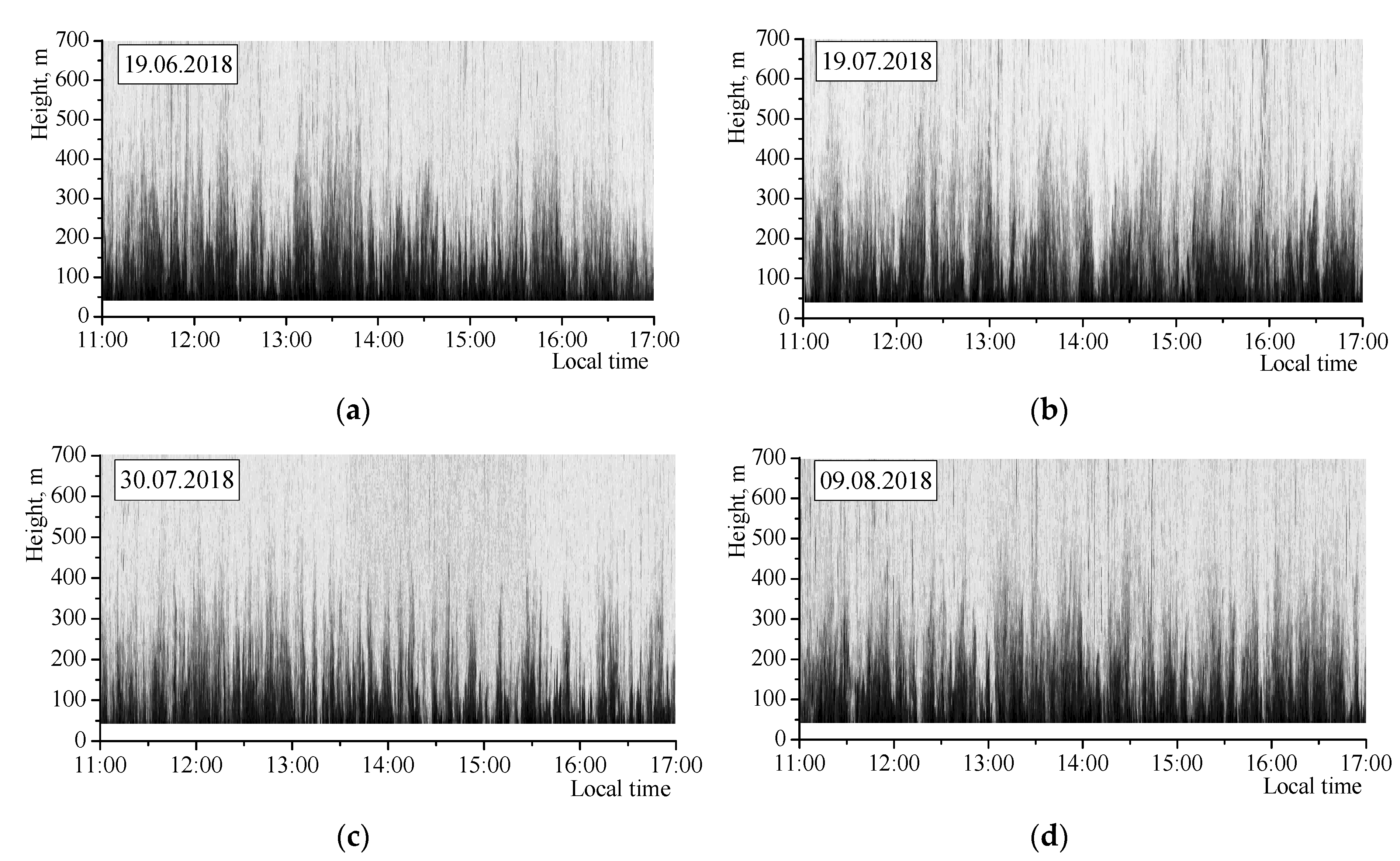
Figure 1. Examples of echograms taken during the days with developed convection in the ABL. Measurements of (a) 19.06.2018, (b) 19.07.2018, (c) 30.07.2018, (d) 9.08.2018.
Atmosphere 10 00711 g001
Figure 2. (a) Echogram; (b) set of instantaneous vertical C n 2 ( H ) profiles and the average profile in the slant channel at the frequency of 2300 Hz; (c) set of average C n 2 ( H ) profiles for different channels at different frequencies; (d) averaged (over all channels and frequencies) C n 2 ( H ) profile (symbols) and model (from Equation (4)) profile (line).
Atmosphere 10 00711 g002
Figure 3. Measurements from 9 June 2019: (a) echogram; (b) air temperature; (c) experimental values of C n 2 ( H , t ) ; (d) model values of C n 2 ( H , t ) as calculated by Equation (8); (e) model values of C n 2 ( H , t ) as calculated by Equation (9); (f) model and experimental C n 2 ( H ) profiles averaged for the period of 11:00–17:00 LT.
Atmosphere 10 00711 g003aAtmosphere 10 00711 g003b
Figure 4. (a) Echogram, (b) distribution of air temperature, (c) “experimental” distribution of C n 2 , (d) model distribution of C n 2 . The scales of temperature and C n 2 values are given to the right.
Atmosphere 10 00711 g004aAtmosphere 10 00711 g004b
Figure 5. Examples of height–time distributions of the air temperature (left column) and the structure characteristic C n 2 (right column). The measurement dates and color scales are given in the figures.
Atmosphere 10 00711 g005aAtmosphere 10 00711 g005b