Abstract
In harvesting operations, simulation verification of hand–eye coordination in a virtual canopy is critical for harvesting robot research. More realistic scenarios, vision-based driving motion, and cross-platform interaction information are needed to achieve such simulations, which are very challenging. Current simulations are more focused on path planning operations for consistency scenarios, which are far from satisfying the requirements. To this end, a new approach of visual servo multi-interaction simulation in real scenarios is proposed. In this study, a dual-arm grape harvesting robot in the laboratory is used as an example. To overcome these challenges, a multi-software federation is first proposed to establish their communication and cross-software sending of image information, coordinate information, and control commands. Then, the fruit recognition and positioning algorithm, forward and inverse kinematic model and simulation model are embedded in OpenCV and MATLAB, respectively, to drive the simulation run of the robot in V-REP, thus realizing the multi-interaction simulation of hand–eye coordination in virtual trellis vineyard. Finally, the simulation is verified, and the results show that the average running time of a string-picking simulation system is 6.5 s, and the success rate of accurate picking point grasping reached 83.3%. A complex closed loop of “scene-image recognition-grasping” is formed by data processing and transmission of various information. It can effectively realize the continuous hand–eye coordination multi-interaction simulation of the harvesting robot under the virtual environment.
1. Introduction
The annual production of grapes worldwide exceeds 77 million tons, 30% of which are fresh grapes [1]. The growing environment of table grapes is complex and seasonal, and harvesting is usually concentrated in one to two months [2]. With an aging population, there is an increasing need for research and development of fresh grape harvesting robots [3]. Hand–eye coordination and algorithm verification are the core of the entire performance of the harvesting robot, which requires a large number of experiments for comparative analysis and optimization verification to achieve optimal hand–eye coordination control and robot performance improvement [4]. However, the harvesting robot is easily limited by natural conditions and collision interference during the experiment. First, the picking will be restricted by many factors, such as harvest season and bad weather [5]. During the experiment, the number of grapes harvested decreased, and the same experimental conditions could not be provided in a realistic vineyard, making the experiments unrepeatable. The second reason is that collisions and interference between the robotic arms, robotic arm and trellis, and fruit leaves easily occur during the operation, which will damage the robotic arm [6]. Therefore, the control of hand–eye coordination urgently needs a virtual simulation platform as a support, and the operational performance and control algorithms of the harvesting robot are simulated. Hence, the development of a virtual simulation platform for hand–eye coordination is of great importance for agricultural robots.
With the rapid development of computer software technology, simulation has been studied more in the field of robotics [6]. The early research for simulation was to perform kinematic analysis and optimal design of robotic arms, and it did not involve the interaction between robots and their environment. In recent years, with the continuous development of virtual reality technology, the simulation of harvesting robot operation environments has been widely used [7]. Different simulations have been realized with Webots [8], Gazebo [9], or V-REP [10] to create virtual environments and harvest robot models [11]. Cao, X [12] proposed an improved RRT algorithm for obstacle avoidance motion planning research in litchi harvesting experiments by building a collision detection model of the robot and obstacles in a virtual environment. Lufeng, L. et al. [13] conducted a virtual simulation on the harvesting behavior of a hardware-in-the-loop grape harvesting robot, calculated anti-touch harvesting envelopes based on visual perception, and verified algorithms for fruit stem recognition, picking point positioning, path planning and other aspects. Shamshiri, R.R. et al. [14] jointly implemented the image moment method visual servo in MATLAB. Fanuc LRMate 200iD 6-DoF manipulator and artificial plant and fruit models were used to simulate a bell pepper robot harvesting scenario and tested on different robotic platforms. However, the current study was only able to explore the motion planning of the robotic arm by manually importing the image information by building a collision envelope of the fruit. There is no way to make the robot interact with the plant and perceive the environment autonomously. This is only a one-way simulation, and there is no way to establish a closed loop of information interaction, not to mention the continuous autonomous realization of hand–eye coordination of harvesting operations.
In other agricultural fields, Iqbal et al. [15] simulated the agricultural environment in a gazebo simulator for field phenotyping and navigation simulation of agricultural robots using LIDAR. Shamshiri et al. [11] built a virtual citrus orchard in V-REP to simulate a mobile robot searching citrus trees in a virtual orchard. Environmental point clouds are created, and various sensors, such as vision and proximity, are designed for obstacle avoidance by the robot. A harvesting operation simulator software was designed by AnyLogic [11] to model the relationship between a grain combine, a grain cart, and a truck. This software also demonstrates the logistical dynamics that are associated with harvesting crops. In the field of industrial robots, Wang et al. [16] used vision sensors in V-REP to identify and detect workpieces for automatic programming of industrial robot deburring. Liu. [17] implemented intelligent grasping simulation training for industrial robots based on a deep learning model framework. However, most of them conduct navigation studies or just use the scenario as a background to explore the robot’s behavior in a virtual environment without establishing interaction with scenario information. Industrial robots or robots in other agricultural fields, such as rice field harvesting, cannot simulate the robot’s autonomous visual perception operations in the face of a consistent operating environment, thus failing to provide precise data realistic support to the robot. In particular, harvesting robots face a much more complex environment than they do, so hand–eye coordination for fully autonomous simulation operation is even less achievable with existing methods.
Therefore, research on hand–eye coordination operation simulation of harvesting robots needs to build a multi-interaction simulation system in complex canopy environments. In this system, the interrelationships between the environment, the fruit target, the camera, the harvesting robot, the robotic arm, and the end effector are established. Relating vision and motion control, the advantages of MATLAB, V-REP, and OpenCV are combined to perform hand–eye coordination operations in complex environments using virtual simulation techniques. This paper is structured as follows. In Section 2, the overall structure of the simulation system is proposed (Section 2.1), and a 3D visualization virtual platform is built to simulate the vineyard scene for harvesting needs (Section 2.2). The communication interface among V-REP, OpenCV and MATLAB is designed (Section 2.3). Based on the visual interaction system, the kinematic model and control system are built in MATLAB, and the data are processed using OpenCV and MATLAB (Section 2.4). In Section 3, we present the integrated running performance of our multi-interaction operating system. Finally, a summary of this study is presented in Section 4.
2. Material and Method
2.1. Overall Scheme
To realize a multi-interaction virtual simulation operation, a vision-based hand–eye coordination experiment platform needs to be built. However, it is quite challenging:
- (1)
- To realize the recognition and positioning of targets by the vision in a virtual environment: This scene is a virtual environment that truly reflects the target and is not simply a virtual creation in an abstract environment. It can truly reflect the geometric size and spatial distribution of the target and truly describe the scaffolding covering the situation. It can also change the color and distribution of fruits according to seasonal changes. The algorithms for target recognition are run autonomously to discover targets and give coordinates in a virtual environment.
- (2)
- Hand–eye coordination operations require the establishment of visual interaction between the robot and individual targets. Based on the visual feedback of the target information, the robot can complete motion planning and be driven to harvest fruit one by one. Instead of artificially inputting the results of camera recognition into the simulation environment and then initiating visual servo, motion planning should be autonomous.
- (3)
- Conducting such simulations in a cross-platform virtual simulation system enables measurements to be made during the run. Data (such as robot collision, robot arm motion pose, visual recognition result, harvesting effect, and system time consumption) are obtained and analyzed for optimization.
To overcome these considerable challenges, my design solution is as follows: First, the joint simulation of multiple platforms must be realized to truly reproduce the operating environment of harvesting robots [18]. However, visual feedback information cannot be processed in V-REP. Therefore, V-REP was combined with multiple FEM software. OpenCV is used as the image processing system to process the output image in V-REP. MATLAB, with powerful data processing capabilities, is used to process the output coordinate information, and the control module is built in Simulink to drive the robot arm movement in V-REP. This cross-platform virtual simulation system that the author built is able to run autonomously, and the modules communicate with each other autonomously. Moreover, by running this platform, it is able to measure the results of robot collision, robot arm pose, and system elapsed time. The overall structure of the cross-platform autonomously coupled simulation system is shown in Figure 1.
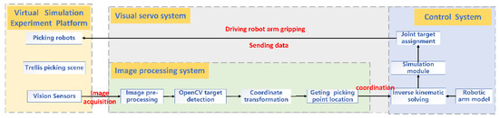
Figure 1.
The overall scheme flow of harvesting robot simulation system.
- (1)
- A virtual simulation platform is built with V-REP software as the core. It contains harvesting robot modeling and virtual vineyard scene modeling, which recreates the virtual environment to simulate harvesting work, and vision sensors to acquire images. In V-REP, the robot arm accepts control information from MATLAB for motion simulation and collision detection [11] (Section 2.2).
- (2)
- To realize communication between V-REP, Python, and MATLAB, we create a data interface between the modules. OpenCV can be called using the remote API in V-REP. V-REP and MATLAB were used to establish a bidirectional communication architecture through an interface for exchanging sensor and robot control information (Section 2.3).
- (3)
- OpenCV is used as an image processing system to receive images from vision sensors in the simulation platform. OpenCV computer vision library and Python language are used to identify and locate images. The picking point information is obtained, and the processed 3D coordinates are sent to the MATLAB simulation module via UDP (Section 2.4).
- (4)
- The D-H method is used for inverse kinematics analysis. The kinematic model of the robotic arms is built in MATLAB. The simulation control module is built in Simulink. The generated data are sent to V-REP so that the robotic arm model in V-REP responds in real-time, and finally, the coordinated control of the grape being recognized and the robotic arm being grasped is realized [19] (Section 2.4).
As shown in Figure 2, the structure of the simulation system designed in this paper is divided into three main modules: (1) the visual perception module (i.e., fruit visual recognition and positioning); (2) the control center (i.e., visual servo); and (3) the actuation module (i.e., fruit grasping) in the virtual reality platform and the communication module [14]. We combine a virtual environment, visual servo, forward and inverse kinematics of robotic arms, and MATLAB control systems to design this cross-software virtual simulation system.
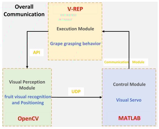
Figure 2.
Structure of the simulation system of harvesting robot.
2.2. Construction of Virtual Simulation Platform
When using the virtual simulation platform for harvesting operations, first, a prototype model of a grape harvesting robot and its operational environment for harvesting needs to be created, and the vision sensors and control script need to be set up, as shown in Figure 3.
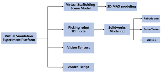
Figure 3.
Flow chart of virtual simulation platform construction.
The virtual environment is built based on the reproduction of a real vineyard, which can reflect the real shading between different branches and fruits and the real, pickable and touchable characteristic relationship between plants and target individuals. The physical features of the models in this platform are all real, collidable, and measurable robot models, not virtual, graphics-based shape models. To prevent the model from taking too long to render in V-REP, the model can be cleverly handled to ensure that the robot runs properly in the simulation platform and does not suffer from insufficient calculation. The vision sensor is used to simulate the D435 depth camera installed on the prototype because it can generate two video streams of depth image and color image during simulation, and the captured image information can be called through a remote API for image identification and positioning. In V-REP, the built-in language LUA can be used to edit the script to control the walking of the harvesting robot chassis, and the starting position of the robot can be randomly determined during the harvesting simulation.
2.2.1. Design and Modeling of Picking Environment
In this study, the physical characteristics of grape clusters were collected by visiting the Erya grape production base in Ding Town, Zhenjiang, to investigate the existing trellis grape cultivation process and the harvesting process of fruit farmers. The first step is to build a trellis skeleton based on the obtained pictures, then draw the vines and branches coiled on the shelf, hang the grapes on top of the trellis, and finally find a suitable material for mapping and rendering to make it have color and material information. Using 3D MAXS software, a model of a standardized trellis vineyard environment with a length of 6 m, a height of 2 m and a width of 1.4 m was constructed. The density of grape distribution and the length of the stems can be adjusted according to the specific requirements of the simulation in this environmental model.
The trellis vineyard environment model created in 3D MAX cannot be used directly for V-REP; thus, it needs to be saved as an STL format file. When importing the model into V-REP, to prevent too many parts of the vineyard model from affecting the speed during simulation, we choose to import in layers and modules, give color and collision properties one by one, and finally generate a virtual harvesting environment model. The results of environment model creation in 3D software and in V-REP are shown in Figure 4.
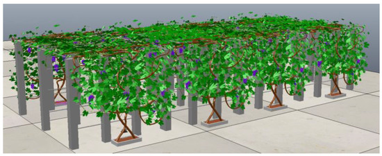
Figure 4.
Environment model.
2.2.2. Modeling of Harvesting Robots
In order to meet the current harvesting requirements of trellis grapes, a dual-arm high-speed grape-picking robot was designed in this lab, considering the overall configuration of the harvesting robot and the operating space of the robot arm [20]. The robot parameters are shown in Table 1, and two six-degree-of-freedom UR5 robotic arms were chosen. The model of the grape harvesting robot built using the 3D software SW is shown in Figure 5a, which is also saved as an STL format file.

Table 1.
Basic robot parameters.
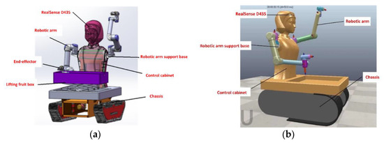
Figure 5.
Model of two-armed grape harvesting robot. (a) Harvesting robot model diagram in SW (b) Harvesting robot model diagram in V-REP.
Since the motion of each part of the robot must be controlled during the simulation, the STL file must be exported by decomposing the model and adjusting the motion relationships according to motion modules such as the travel chassis, robot arm, and end-effector. Moreover, the internal structure of the harvesting robot model created by SW is complex, and if it is directly imported into V-REP without simplification, the generated model takes too long to render and has poor real-time performance. Therefore, the simulation model is simplified by deleting a large number of parts and merging triangles into convex packages. Finally, tick the options for collision detection, calculation, etc.
These parts can only be used as the "thin shell" shape of the robot and do not have kinetic properties. If the robot is to have kinematic characteristics, the following operations are also needed.
- (1)
- Setting the properties of the robot arm model. The key joint features of the robotic arm model are extracted and set as convex packages and added motion joints. By setting the dynamic properties of each joint of the robot arm and adjusting the inheritance relationship, each joint is constrained to the corresponding upper-level joint [21]. In turn, the hierarchical tree of the robot arm joint model is constructed. Finally, the drive, mass and moment of inertia are added to the robot arm joints, and the rotation speed is set for the robot arm model according to the actual prototype.
- (2)
- Setting the end-effector. The end-effector and UR5 robot arm are fixed together by a “force sensor”.
- (3)
- Setting up the robot chassis. The crawler-type chassis is found in the model library that comes with V-REP and is dragged into the page. By adding a mechanical “force sensor”, the arm and the chassis, which have mechanical properties, are fixed and connected as a whole.
All joints, robotic arm end-effectors, and chassis are assembled to the body and the hierarchical tree is adjusted. Thus far, the grape harvesting robot model with kinematic properties has built, as shown in Figure 5b.
2.2.3. Configuration of Vision Sensors
The subject is photographed by the vision sensor in V-REP, which can obtain grayscale, RGB, and depth information. The image can be processed. The vision sensor generates two streams of data during simulation: color image and depth image, which are updated each simulation cycle. The images are acquired and saved through a vision sensor, which can be processed using third-party software such as MATLAB and Python.
It can be seen in Figure 6 that the vision sensor "Perspective projection-type" was selected to be mounted on the robot head at a position 1.8 m above the ground to simulate the depth camera D435 on the real prototype for fruit location identification. The visual sensor in V-REP is the same as D435, which uses the method of RGB color camera combined with a Depth camera to obtain the three-dimensional information of points. Therefore, this study uses the vision sensor in V-REP to effectively simulate the functions of the Realsense D435 depth camera installed on the actual harvesting robot [11].
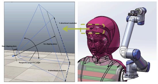
Figure 6.
Vision sensor selection and installation.
The field of view (Persp. angle) and the Resolution (X/Y) were adjusted, and the vision sensor properties were set. According to the robotic arm operating space, the robot is required to have a harvesting range of less than 850 mm in one direction, so the Near clipping plane is set to 0, and the far-clipping plane is set to 1 m. A floating view is added to the scene and associated with the vision sensor, and the scene is displayed, as shown in Figure 7.
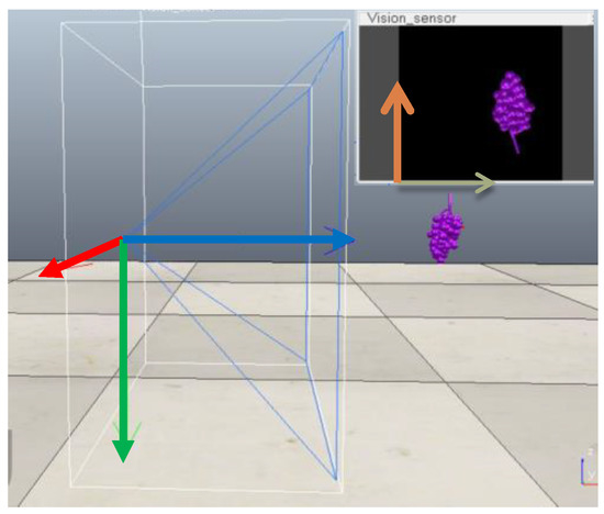
Figure 7.
Establishment of vision sensor coordinate system.
2.2.4. Control Scripting
The built-in scripting program Lua language can control the harvesting robot movement in V-REP, including programs such as the chassis movement, the camera shooting program and the drive of the robot arm joints.
As the flow is shown in Figure 8, the chassis of this paper adopts the “start–stop” walking mode under the trellis road. The vision system of the robot obtains the image information in the current field of view in real-time. When the effective picking point appears in the field of view, the chassis stops moving, and the end-effector completes the clip operation; when there are no grapes in the working space of the robotic arm, the robot continues to move forward to the next working space, starting the next cycle of the grape harvesting operation.
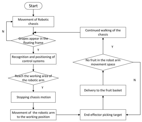
Figure 8.
Control script simulation operation flow chart.
The overall effect of the harvesting robot running in the virtual vineyard system simulation is shown in Figure 9.
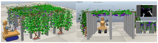
Figure 9.
Overall effect of simulation platform.
2.3. Communication Interface Design
V-REP, as a strong interactive 3D visual simulation platform, is programmed in two ways: embedded scripting and a remote client application programming interface. The communication between multi-platforms of the harvesting robot simulation control system is needed to connect robot models, and identify algorithms and controllers, thus realizing data transfer between models. The simulation platform is jointly controlled by third-party software that regularly sends instructions for the simulation, with the operation mode shown in Figure 10a and the intercommunication mechanism between V-REP and MATLAB, as well as Python [14], as shown in Figure 10b.
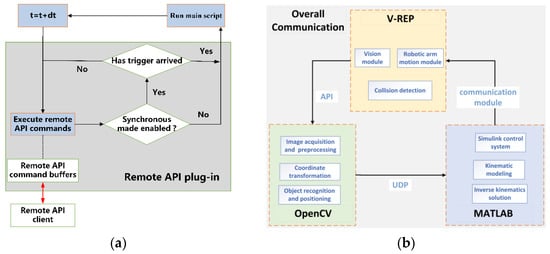
Figure 10.
Simulation system communication mechanism. (a) Remote API call method. (b) Communication method between software.
- (1)
- The scripting program of the model was modified, and the code “simRemoteApi.start (19999)” was entered to establish the connection between V-REP and Python. By acquiring the camera handle, the images sent by the vision sensors in the V-REP can be read [22].
- (2)
- Communication between OpenCV and the control system is achieved by sending the 3D coordinates of the recognized image to MATLAB using UDP and custom functions.
- (3)
- The “Synchronization Trigger” and “Start Connection” modules were added to Simulink. The simulation time is set to 0.05 s, the same as in V-REP, to establish a synchronous simulation environment. The robot system model in V-REP is connected to the Simulink control program so that it can continuously receive data from MATLAB to respond to control.
2.4. Visual Servo Simulation in Virtual Scene
The images acquired by the vision sensors are received and processed using the OpenCV computer vision library and Python language. The processed 3D coordinates of the picking points with depth data are sent to the MATLAB simulation module via UDP. The robot is analyzed in MATLAB for forward and inverse kinematics, and Simulink is used to build a simulation module to control the robot’s arm motion. The D-H method is used to establish the coordinate system of each connecting rod to write out the parameters of each connecting rod for inverse kinematics analysis, and the angle values of the six joints of the robot arm are solved. The angle is sent to the V-REP, which drives the end-effector of the harvesting robot to realize the grasping behavior and the identification and grasping of the grape berries. The simulation flow of the visual servo system of the harvesting robot in the virtual environment is shown in Figure 11.
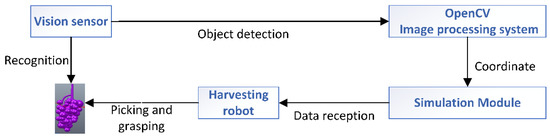
Figure 11.
Structure schematic of the vision servo system.
2.4.1. Visual Recognition and Positioning
The harvesting robot needs to know the position information of the target fruit relative to the robotic arm before it can control the robot arm to make the end-effector reach the desired position for harvesting. Thus, it is necessary to study visual positioning and object recognition technology, and the overall structure of the visual recognition system is shown in Figure 12 [21].
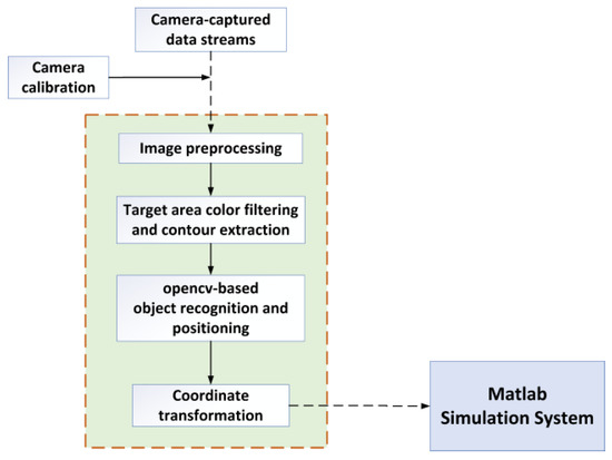
Figure 12.
Harvesting robot object detection and positioning flow chart.
Image-based servo control cannot be achieved without camera calibration, internal and external parameters are obtained by camera calibration. The internal reference matrix of the camera is related to its focal length in the V-REP. The external reference matrix of the camera consists of a rotation matrix and a translation vector matrix. Among them, the rotation matrix R represents the camera’s rotation concerning the world coordinates; the translation vector matrix T represents the mounting position of the sensor in the world coordinate system.
The depth data of each pixel point in the image is extracted exactly by calling the relevant API function [23]. The depth data in the vision sensor is fetched using “sim.getVisionSensorDepthBuffer”. Based on the image data and grape hanging characteristics, the original image is transformed from the RGB color space with strong color component correlation to the HSV color space with low correlation, and color extraction is performed. Median filtering is performed in the H component of HSV color space, and the target outline is extracted by setting the color threshold [24]. The grape object is divided, and the results of binarization are shown in Figure 13.
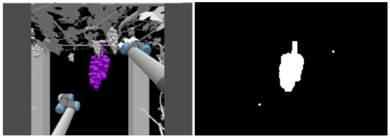
Figure 13.
Image recognition results.
The pixel coordinates of the grape center of mass in the image are obtained with the image recognition system. Based on the internal reference matrix of the camera calibration, this two-dimensional coordinate is converted under the camera coordinate system. The hand–eye relationship matrix between the camera and the robotic arm is obtained by v-rep, and the 3-dimensional coordinates of the target point are obtained under the base coordinates of the robotic arm.
In V-REP, the vision sensor acquires coordinates in the way shown in Figure 14. If the point “q” is the centroid position (X, Y) of the target in the image plane that has been acquired, the point “p” is the actual spatial location of the block diagram, and the depth value “ZP” is the value obtained by the depth camera. Therefore, the spatial coordinates of the grape centroid in the camera coordinate system are XC, YC, and ZP. Then, through the conversion between the world coordinate system, the camera coordinate system, and the image coordinate system [25], the three-dimensional coordinates (XW, YW, ZW) of the centroid of the target area in the world coordinates are obtained. Then, this information is sent to the MATLAB control module [26].
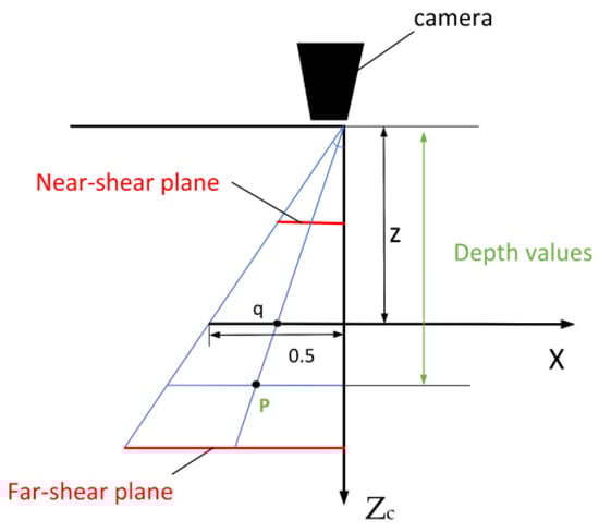
Figure 14.
Vision sensor coordinate projection diagram.
2.4.2. Robotic Arm Modeling and Kinematic Analysis
The six-degree-of-freedom UR5 robotic arm was chosen for the platform. The D-H method [27] is used to describe the geometric relationship between the connecting rods. Based on the established robot linkage coordinate system, the D-H parameters of the UR5 robot [5] can be obtained, as shown in Table 2.
Table 2.
D-H parameter table of harvesting robotic arm.
Based on the above parameters, the 3D kinematic model of the harvesting robotic arm is built by using the Robotics Tools box in MATLAB. Depending on the different types of modeling, the end poses calculated during MATLAB simulation may have a certain degree of error with the end poses in the V-REP environment. Therefore, the following adjustments need to be carried out.
- (1)
- First, we observe the difference in the initial posture of the robot arm in the robot toolbox and V-REP. The initial pose of the UR5 robot is modified until it matches the initial position in the MATLAB toolbox.
- (2)
- In V-REP, we label each joint position and perform the simulation again with the new D-H parameters to observe whether the model in MATLAB is consistent with that in V-REP.
- (3)
- If multiple random points are taken to verify that the positions are basically the same, the D–H model established by the abovementioned method is more accurate. The model of the robot arm is shown in Figure 15.
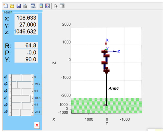 Figure 15. Harvesting robotic arm model in MATLAB.
2.4.3. Construction of Simulink Control System
Simulink is a visualization tool based on MATLAB block diagram design, which is often used for modeling and simulation of linear or nonlinear systems, digital signal processing and digital control. Simulink, as an external control program of V-REP, is able to receive the position information sent by OpenCV. The Simulink control module is built to realize MATLAB to assign values to the robotic arm joints to grasp the grape. The flow chart of the control system is shown in Figure 16.
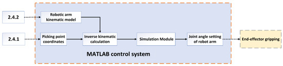
Figure 16.
Simulation control system flow chart.
The Simulink control system is divided into three main parts: 1. V-REP connection module; 2. inverse kinematics module; 3. controller module.
- (1)
- The V-REP and MATLAB communication module has been introduced in “2.3”. The purpose is to realize the communication with MATLAB and establish the simulation environment.
- (2)
- The kinematic analysis of the robotic arm is shown in Figure 17, and the robot arm inverse kinematics equation is as follows.
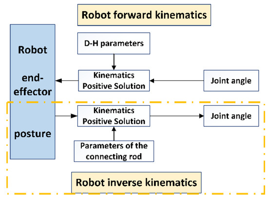 Figure 17. Kinematic analysis of robotic arm.
Point “P” represents the identified target point, “Pb” corresponds to the coordinates of point “P” in the coordinate system at the end of the robot arm and “Pa” is the representation of point “P” in the fixed coordinate system. The hand grasp needs to be moved to the target point to achieve the “Pb” to “Pa”. is the homogeneous matrix of the robotic arm. The parameters of the homogeneous matrix are related to six joint angles of the robot arm, so these six joint angles can be solved using inverse kinematics.
- (3)
- Construction of simulation control system in Simulink. Since the posture and position of the robotic arm end-effector when it reaches point P is known—based on the “ikcon” inverse kinematics program—the angle “θ” that the six joints should be rotated, which is used as the movement of the robot arm in the system, can be calculated. Finally, each joint is controlled to rotate to the target position to achieve the end-effector grasping action, as shown in Figure 18.
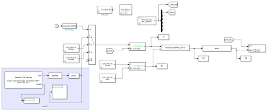 Figure 18. Structure diagram of the harvesting robot control system.
3. Test and Evaluation
3.1. Simulation Environment and Conditions
As a method and application meant to simulate the behavior of real systems, the simulation includes two main steps: establishing simulation models and conducting simulation. The operating equipment of this simulation is a Lenovo R9000P laptop with Windows 11 as the operating system. The software environment uses Anaconda3 (Python 3.65), and V-REP 4.0, the image processing algorithm running environment is OpenCV4.1.0, and the training and testing platform deep learning framework uses PyTorch1.2.0.
The virtual simulation system is able to obtain different outputs which are measurable, observable and obtained by statistics by entering different parameters. The table of parameters is shown in Table 3. The effectiveness of the harvesting operation includes the correct fruit identification rate, harvesting success rate, leakage rate and running time, etc. The robot simulation platform with the harvesting environment and the machine model is shown in Figure 19. Another camera was set up on the right side of the grape bunches to record details of the grape harvesting operation. Four different directional lights are set up to simulate uniform solar illumination during the day in a trellis environment, and “light is enabled” is used as the lighting message, and the brightness is adjustable. To verify the operational performance of the simulation system in a single cycle, the following virtual simulations are conducted.
Table 3.
Incoming and outgoing parameters.
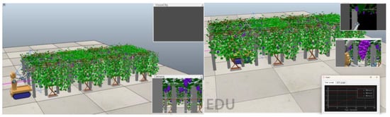
Figure 19.
Virtual simulation harvesting platform (pre-running/running).
Simulation 1: To verify the feasibility of visual recognition within the virtual simulation system and whether the positioning accuracy meets the requirements, five simulations of a multi-target virtual visual recognition localization were performed at random sites. The imaging system can be checked for recognition at locations with different berry sparsity and fruit sizes. When conducting experiments, the traditional algorithm based on feature extraction was not effective in detecting overlapping fruits, so we repeated the simulation with the same API interface for deep learning, which is being studied by the classmates, under the same conditions. The feasibility of these two algorithms in the system is verified, and the results are compared.
Simulation 2: The simulation was carried out to simulate the joint motion of the robot arm under the virtual simulation system to check whether the model in V-REP can respond to the control commands issued in Simulink for motion. First, the communication test of the simulation platform is performed. The joint space drive model is built in Simulink, as shown in Figure 20. It consists of three main parts: (1) the connection module between Simulink and V-REP; (2) setting a set of joint target positions, using it to drive the joints of the robot arm and control the arm to reach the target point position; and (3) the input of the joint angle of the robot arm. The first three joints are driven with sine wave input, and the rest of the joints are kept constant at the 0 position.
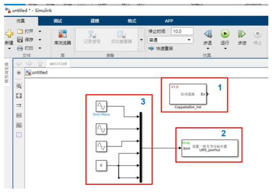
Figure 20.
Control system.
Second, the control model with four limit positions set by Dummy in Simulink is built quickly. Whether the robotic arm reaches the specified position as planned is verified, and the optimal range and attitude of the robotic arm during harvesting are searched for within the workspace.
Simulation 3: As a typical berry fruit, grapes have soft and thin skin and a high density of bunches per unit area. Because harvesting robots are expensive and easily damaged, collisions must be strictly avoided during actual operations. Therefore, real-time collision detection needs to be conducted before harvesting [28]. The harvesting simulation is likely to cause three types of collisions: one is a collision between the harvesting robot mechanism itself; the second is also likely to cause a collision between the robot arm and the grapes, leaves, and trellis; and the third is also a phenomenon of interference between the two arms. For these three cases, easily colliding objects are set up as models with physical characteristics, and collision tests are designed.
The collision detection module can detect two colliding entities or collisions generated between one object and all other objects, and the collision status between colliding objects can be displayed in different colors. The objects for collision detection in V-REP are selected, e.g., here, the robot arm and the scaffolding are selected for collision detection. The “collidable” property is set to true, and the collision detection module point is opened. The "Add new collision object" is clicked, and the robot arm and scaffold to be collision-detected are selected. This collision detection collection is named for use in the built-in script. If there is a collision between the two during the harvesting robot’s operation, the color of the trellis will change to remind you that there is interference here.
Simulation 4: To verify the overall harvesting cycle that the harvesting robot can run successfully, enabling cross-platform interaction from scene to image and from image to motion control. The "robot virtual environment one-cycle joint simulation" is needed. The vision sensor of the harvesting robot recognizes one fruit, the angle information is sent to V-REP through the Simulink control module in MATLAB, and the robotic arm grabs the grape to transport it to the release point and places it in the fruit basket. This is a single-cycle simulation. The entire harvesting process of the robotic arm in moving, positioning, harvesting and returning is tested, monitored and recorded. The program is run, and the simulation is repeated 30 times.
3.2. Results and Discussion
3.2.1. Results
Simulation 1: The image of the camera is seen after starting the simulation. By calling OpenCV and improving the yolo v4 model, the fruits in the field of view are identified. The coordinates of the target point are calculated based on the detected depth information. The visual recognition and positioning test results of the harvesting robot are shown in Figure 21, and the results are shown in Table 4.
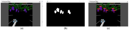
Figure 21.
Visual recognition and positioning. (a) Vision sensor field of view. (b) OpenCV image processing. (c) YOLO v4 recognition results.
Table 4.
Running time and recognition accuracy.
The virtual simulation system takes 0.56 s on average in a random environment. The system runtime includes the time to acquire the image, the time to process the image, and the positioning time. The whole process includes a vision sensor recognition-processing system to derive 3D coordinates-results of image processing sent from Python to MATLAB. As shown in Table 3, the recognition time of each image frame is less than 0.2 s. The OpenCV image processing system was able to successfully identify 92% of the targets. The accuracy of the YOLO v4 deep learning model is high, and the detection success rate for grapes can reach 96% on average.
Simulation 2: The robot arm makes a reciprocating motion in V-REP. The simulation takes 1.8 s to traverse the 3 points, and the whole process responds quickly and without delay. The robot arm can accurately execute motion to reach the specified position, and the robot arm can reach three specific points "left-front-right" within the maximum movement space. The simulation shows that the joint simulation between V-REP and MATLAB across platforms is successful [26].
Simulation 3: The results of the collision detection are shown in Figure 22, where the scaffold turns red, indicating that an obstacle is encountered during the travel process and the simulation is ended. Different collision colors are set according to the three different types of interferences generated, and collision position is distinguished by color change. If the robot hits a known target, such as its own body or another arm, it should be avoided by planning; if during work, the robot collides with a trellis or a target with relatively changing objects, then obstacle avoidance by means of vision or distance sensors, etc., is needed. Ultimately, it provides research directions for further optimization.
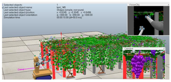
Figure 22.
Collision detection results.
Simulation 4: The Simulink control module was used to build a complete simulation system for the robot arm. Multiple single-cycle joint simulations in a virtual environment of the harvesting robots were conducted according to the methods and steps described above. During the operation, the relevant data are recorded in real-time, and the operation effect is observed. It is observed that when the robot hand claw reaches the set position, the robot arm briefly stops. When the recognition result appears in the floating window of the vision sensor in V-REP, MATLAB drives the robot arm to the picking point, the end-effector grabs the target fruit and puts it into the fruit box, and finally ends this simulation. The harvesting process is shown in Figure 23.
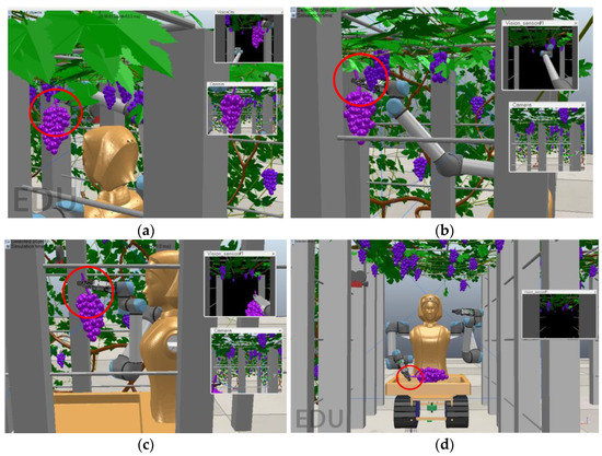
Figure 23.
Simulation of robotic picking process in virtual environment. (a) Close to the target. (b) Picking time. (c) On the way back. (d) Putting in fruit basket.
Thirty joint simulations of hand–eye coordination operation of harvesting robots were conducted on this simulation platform, and the average harvesting time of a single bunch was 6.5 s, 0.7 s in the visual recognition link, and 5.8 s in the grasping link. Among them, 25 samples were successfully positioned for grasping, and only five samples failed to achieve accurate grasping. The accuracy rate of recognition reached 92%, and the success rate of picking point grasping was 83.3%.
3.2.2. Discussion
In simulation 1, both algorithms are feasible in the virtual simulation platform. However, in the process of grape detection, it is found that the algorithm based on traditional feature extraction is not effective in identifying fruits in overlapping parts. So, the traditional image processing algorithm was replaced with the improved YOLO v4 model, thus achieving successful segmentation of overlapping grapes.
Simulations 1 and 2 verify that the joint simulation communication between the virtual simulation platform and the visual recognition and positioning system and MATLAB control system is continuous and can be executed autonomously. In simulation 3, the collision position is distinguished by color change. This collision detection test can be used as a marker to judge the success of the harvesting simulation and as a parameter indicator to provide a basis for anti-collision planning in subsequent studies.
The time consumption of simulation 4 is mainly determined by the size of the harvesting robot model, the number of target points in the field of view, and whether the control system is well-designed. The reasons for the unsuccessful tests in simulation 4 are as follows. (1) The effective distance of the vision sensor set in this simulation platform is 1 m, and the working space of the robotic arm is smaller than the vision sensor’s field of view, which may result in the sensor being able to recognize the target, but the robotic arm is unable to grasp. (2) the robot arm did not plan its motion, which led to the robot arm passing through the robot body or colliding with the scaffolding due to interference between the two arms. (3) Too much fruit in the field of view causes disorderly movement of the robot arm and no way to pick individual targets. Simulation 4 verifies the feasibility of a cross-platform virtual simulation system. A complex closed loop of "scene-image recognition-harvesting and grasping" is formed by data processing and transmission of various information. It can effectively realize the continuous hand–eye coordination multi-interaction simulation of the harvesting robot under the virtual environment.
4. Conclusions and Future Works
In this study, a new multi-interaction simulation of hand–eye coordination system for a grape harvesting robot was designed. The 3D solid visualization trellis is used as a virtual environment, and the harvesting robot is used as the simulation object. Multi-software federation to establish their communication and cross-software sending of image information, coordinate information, and control commands. Then, the fruit recognition and positioning algorithm, forward and inverse kinematic model and simulation model are embedded in OpenCV and MATLAB, respectively, to drive the simulation run of the robot in V-REP, and, finally, the measurement and evaluation of the robot are realized. The communication between V-REP, OpenCV, and MATLAB and the automatic operation of the multi-interaction simulation process between the trellis-harvesting robots are realized through API, UDP, and joint simulation modules. By building this simulation platform, a complex closed loop of "scene-image recognition-grasping" is formed by data processing and transmission of various information. It can effectively realize the continuous hand–eye coordination multi-interaction simulation of the harvesting robot under the virtual environment.
A total of four simulations were designed to verify the feasibility of cross-platform simulation of autonomously operating hand–eye coordination for grape harvesting robots. The robot interacts with a highly variable and dynamic complex environment, resulting in a picking simulation with hand–eye coordination autonomously. This work provides a good basis for further implementation of continuous visual servo harvesting simulation. For example, some researchers are currently looking to use more manipulators to increase the productivity of grape harvesting. However, the increase in robotic arms will result in less space for the actual movement of individual robotic arms, and the control system will be more complicated to avoid interference between the arms, which in turn will affect the harvesting efficiency. Therefore, how many manipulators are used and how to improve the control system of the manipulator to maximize the picking efficiency is the next focus of the authors’ research using this virtual simulation system.
In addition, a real robot will face many challenges during harvesting in a trellis environment, such as more obstacles in the natural environment, uneven road surface, sunlight effects on fruit recognition, leaf shading of fruit, obstacle avoidance between arms, and multi-objective fruit picking strategy planning are all things that can be discussed in further research. Based on this virtual multi-interactive operating system, the robotic navigation in the environment, various studies on the influence of light intensity changes on recognition rate, visual-servo dual-arm cooperative parallel operation, and picking sequence planning of different fruit densities and distributions will be reported in the next study.
Author Contributions
Conceptualization, J.L. (Jizhan Liu) and J.L. (Jin Liang); methodology, J.L. (Jizhan Liu), J.L. (Jin Liang) and J.W.; software, J.L. (Jin Liang); validation, J.L. (Jin Liang), Y.J. (Yingxing Jiang) and J.L. (Jizhan Liu); formal analysis, J.L. (Jin Liang), J.L. (Jizhan Liu), J.W. and S.Z.; investigation, J.L. (Jin Liang) and J.L. (Jizhan Liu); resources, J.L. (Jizhan Liu) and Y.J. (Yucheng Jin); data curation, J.L. (Jin Liang); writing—original draft preparation, J.L. (Jin Liang); writing—review and editing, J.L. (Jin Liang), J.L. (Jizhan Liu) and S.Z. All authors have read and agreed to the published version of the manuscript.
Funding
The work was supported by the National Natural Science Foundation of China (NSFC) (No. 31971795), Project of Jiangsu Modern Agricultural Machinery Equipment & Technology Demonstration and Promotion (No. NJ2021-13), Project of Faculty of Agricultural Equipment of Jiangsu University (No. 4111680002), Project of Faculty of Agricultural Equipment of Jiangsu University (No. 5543000001) and Priority Academic Program Development of Jiangsu Higher Education Institutions (No. PAPD-2018-87).
Institutional Review Board Statement
Not applicable.
Informed Consent Statement
Not applicable.
Data Availability Statement
Not applicable.
Conflicts of Interest
The authors declare no conflict of interest.
References
- Jin, Y.; Liu, J.; Wang, J.; Xu, Z.; Yuan, Y. Far-near combined positioning of picking-point based on depth data features for horizontal-trellis cultivated grape. Comput. Electron. Agric. 2022, 194, 106791. [Google Scholar] [CrossRef]
- Fu, L.; Gao, F.; Wu, J.; Li, R.; Karkee, M.; Zhang, Q. Application of consumer RGB-D cameras for fruit detection and localization in field: A critical review. Comput. Electron. Agric. 2020, 177, 105687. [Google Scholar] [CrossRef]
- Jin, Y.; Yu, C.; Yin, J.; Yang, S.X. Detection method for table grape ears and stems based on a far-close-range combined vision system and hand-eye-coordinated picking test. Comput. Electron. Agric. 2022, 202, 107364. [Google Scholar] [CrossRef]
- Lufeng, L.; Xiangjun, Z.; Qinghua, L.; Zishang, Y.; Po, Z.; Juntao, X. Virtual Simulation and Prototype Test for Behavior of Robot in Picking Process. Trans. Chin. Soc. Agric. Mach. 2018, 49, 34–42. [Google Scholar]
- He, Z.; Ma, L.; Wang, Y.; Wei, Y.; Ding, X.; Li, K.; Cui, Y. Double-Arm Cooperation and Implementing for Harvesting Kiwifruit. Agriculture 2022, 12, 1763. [Google Scholar] [CrossRef]
- Cheng, K.; Wang, Q.; Yang, D.; Dai, Q.; Wang, M. Digital-twins-driven semi-physical simulation for testing and evaluation of industrial software in a smart manufacturing system. Machines 2022, 10, 388. [Google Scholar] [CrossRef]
- Qiang, L.; Jun, W.; Jun, Z.; Po, Z.; En, L.; Peng, Z.; Jie, Y. Obstacle avoidance path planning and simulation of mobile picking robot based on DPPO. J. Syst. Simul. 2022, 1–12. [Google Scholar] [CrossRef]
- Michel, O. Cyberbotics ltd. webots™: Professional mobile robot simulation. Int. J. Adv. Robot. Syst. 2004, 1, 5. [Google Scholar] [CrossRef]
- Koenig, N.; Howard, A. Design and use paradigms for gazebo, an open-source multi-robot simulator. In Proceedings of the 2004 IEEE/RSJ International Conference on Intelligent Robots and Systems (IROS) (IEEE Cat. No. 04CH37566), Sendai, Japan, 28 September–2 October 2004; pp. 2149–2154. [Google Scholar]
- Rohmer, E.; Singh, S.P.; Freese, M. V-REP: A versatile and scalable robot simulation framework. In Proceedings of the 2013 IEEE/RSJ International Conference on Intelligent Robots and Systems, Tokyo, Japan, 3–7 November 2013; pp. 1321–1326. [Google Scholar]
- Shamshiri, R.R.; Hameed, I.A.; Pitonakova, L.; Weltzien, C.; Balasundram, S.K.; Yule, I.J.; Grift, T.E.; Chowdhary, G. Simulation software and virtual environments for acceleration of agricultural robotics: Features highlights and performance comparison. Int. J. Agric. Biol. Eng. 2018, 11, 15–31. [Google Scholar] [CrossRef]
- Cao, X.; Zou, X.; Jia, C.; Chen, M.; Zeng, Z. RRT-based path planning for an intelligent litchi-picking manipulator. Comput. Electron. Agric. 2019, 156, 105–118. [Google Scholar] [CrossRef]
- Luo, L.; Zou, X.; Cheng, T.; Yang, Z.; Zhang, C.; Mo, Y. Design of virtual test system based on hardware-in-loop for picking robot vision localization and behavior control. Trans. Chin. Soc. Agric. Eng. 2017, 33, 39–46. [Google Scholar]
- Shamshiri, R.R.; Hameed, I.A.; Karkee, M.; Weltzien, C. Robotic harvesting of fruiting vegetables: A simulation approach in V-REP, ROS and MATLAB. Proc. Autom. Agric. Secur. Food Supplies Future Gener. 2018, 126, 81–105. [Google Scholar]
- Iqbal, J.; Xu, R.; Sun, S.; Li, C. Simulation of an autonomous mobile robot for LiDAR-based in-field phenotyping and navigation. Robotics 2020, 9, 46. [Google Scholar] [CrossRef]
- Chun, W.; Yuan, H.; Peng, G. Research on Deburring Path Generation based on Vision Sensor. J. Dalian Jiaotong Univ. 2022, 43, 64–67. [Google Scholar] [CrossRef]
- Liu, J. Research on Robot Grasping Simulation Training Technology Based on Deep Learning; Harbin Institute of Technology: Harbin, China, 2018. [Google Scholar]
- De Melo, M.S.P.; da Silva Neto, J.G.; da Silva, P.J.L.; Teixeira, J.M.X.N.; Teichrieb, V. Analysis and Comparison of Robotics 3D Simulators. In Proceedings of the 2019 21st Symposium on Virtual and Augmented Reality (SVR), Rio de Janeiro, Brazil, 28–31 October 2019; pp. 242–251. [Google Scholar]
- Jin, Y.; Gao, Y.; Liu, J.; Hu, C.; Yao, Z.; Li, P. Hand-eye Coordination Planning with Deep Visual Servo for Harvesting Robot. Trans. Chin. Soc. Agric. Mach. 2021, 52, 18–25+42. [Google Scholar]
- Jiang, Y.; Liu, J.; Wang, J.; Li, W.; Peng, Y.; Shan, H. Development of a dual-arm rapid grape-harvesting robot for horizontal trellis cultivation. AI Sens. Robot. Plant Phenotyping Precis. Agric. 2022, 16648714, 348. [Google Scholar] [CrossRef] [PubMed]
- Nozali, T. Numerical simulation and visualization experiment of solid particle motion affected by parameters of flow in tapered drum rotating type separator, Asia Simulation Conference-international Conference on System Simulation & Scientific Computing. In Proceedings of the Asia Simulation Conference 2008/the 7th International Conference on System Simulation and Scientific Computing (ICSC ‘2008), Beijing, China, 10–12 October 2008. [Google Scholar]
- Hong, Z.; Cheng, W. Virtual Simulation Platform for Remote Control Based on Web and V-REP. Comput. Technol. Autom. 2021, 40, 16–20. [Google Scholar] [CrossRef]
- Zhen, L. The Kinematic Simulation and Design of Kiwifruit Picking Manipulator; Northwest A&F University: Xianyang, China, 2015. [Google Scholar]
- Wang, Z.; Lu, H.; Geng, W.; Sun, Z. OpenCV-based target detection and localization system for fruit picking robots. Electron. Technol. Softw. Eng. 2022, 220, 137–140. [Google Scholar]
- Lei, L.; Yang, W.; Dong, Q.X.; Zhang, X.; Zhang, L. Visual Positioning Method for Handle of Aircraft D.3oor. Sci. Technol. Vis. 2017, 31–34. [Google Scholar] [CrossRef]
- Chao, Z.; Bing, T.; Wei, H. Application of Robot Simulation based on V-REP and MATLAB. Shipboard Electron. Countermeas. 2020, 43, 111–114+128. [Google Scholar] [CrossRef]
- Li, M. The Research on Mechanical System Design and Key Technology of Chinese Prickly Ash Picking Robot; Lanzhou University of Technology: Lanzhou, China, 2019. [Google Scholar]
- Qi, R.; Zhou, W.; Wang, T. An obstacle avoidance trajectory planning scheme for space manipulators based on genetic algorithm. Jiqiren/Robot 2014, 36, 263–270. [Google Scholar]


Disclaimer/Publisher’s Note: The statements, opinions and data contained in all publications are solely those of the individual author(s) and contributor(s) and not of MDPI and/or the editor(s). MDPI and/or the editor(s) disclaim responsibility for any injury to people or property resulting from any ideas, methods, instructions or products referred to in the content. |
© 2023 by the authors. Licensee MDPI, Basel, Switzerland. This article is an open access article distributed under the terms and conditions of the Creative Commons Attribution (CC BY) license (https://creativecommons.org/licenses/by/4.0/).