
Mica/Epoxy-Composites in the Electrical Industry: Applications, Composites for Insulation, and Investigations on Failure Mechanisms for Prospective Optimizations


Abstract
:
1. Definition, Nomenclature, Composition, and Occurrence
2. Physical and Chemical Properties of Mica
3. Mica in Technical Application
- -
- Addition of colors (color industry)
- -
- Filling material (rubber industry)
- -
- Filling material (for molding compounds)
- -
- Silky gloss (wallpaper production)
- -
- Sheatings of welding rods
- -
- Addition for exterior rendering (construction industry)
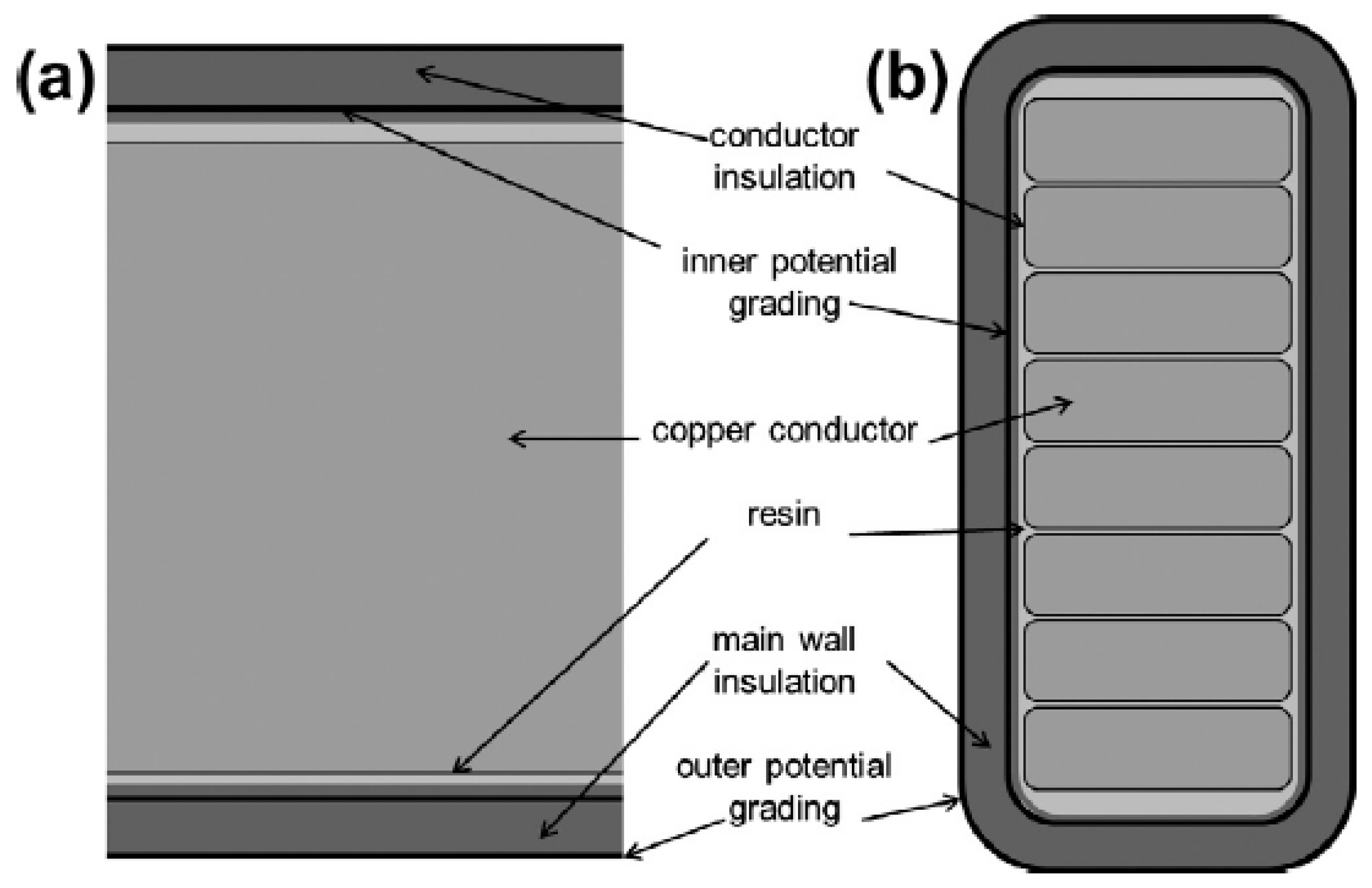
4. Mica as an Insulation Material
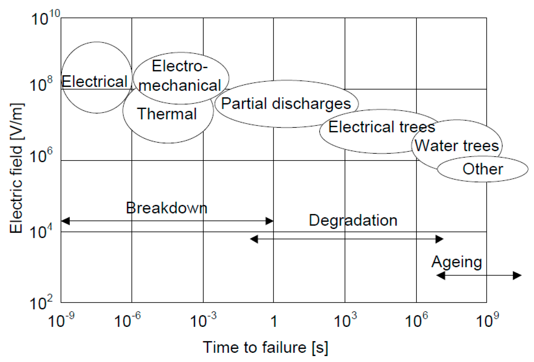
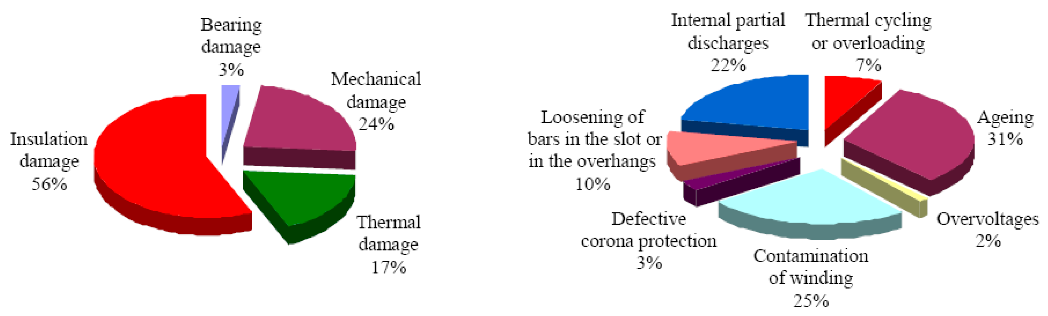
5. Insulation Failure in Power Generators
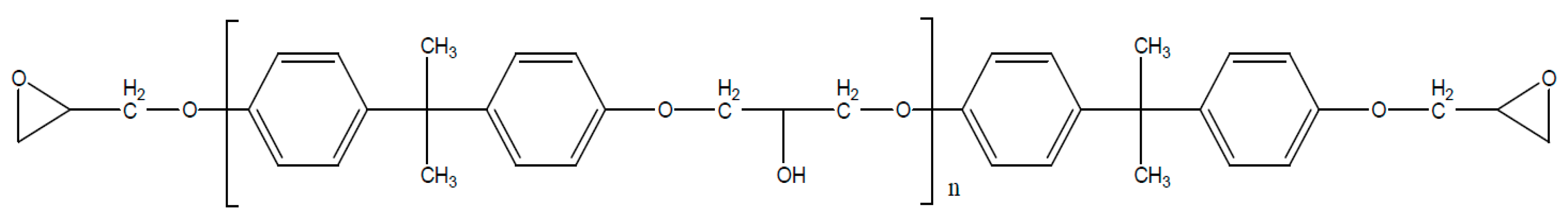
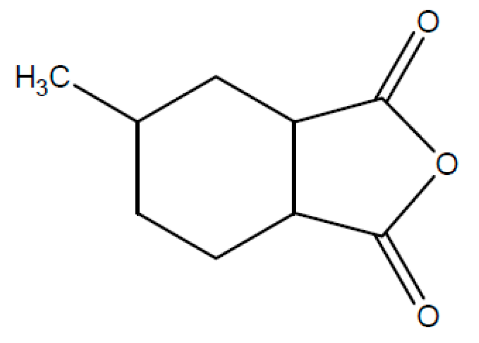
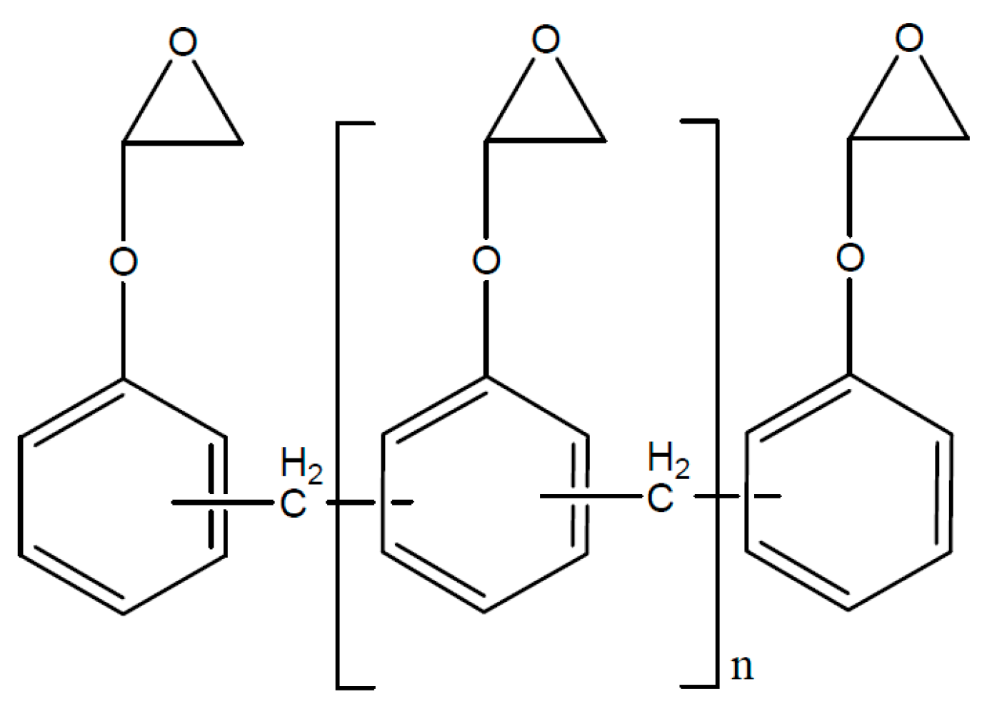
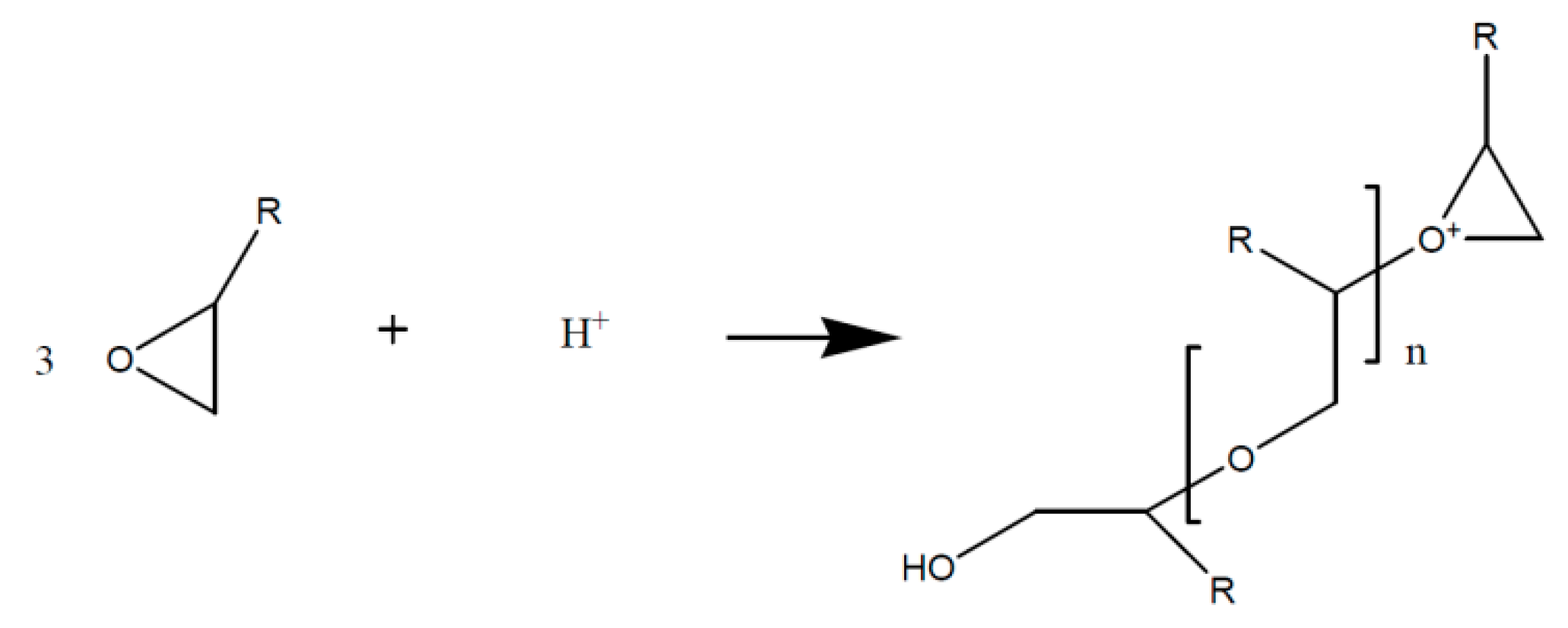
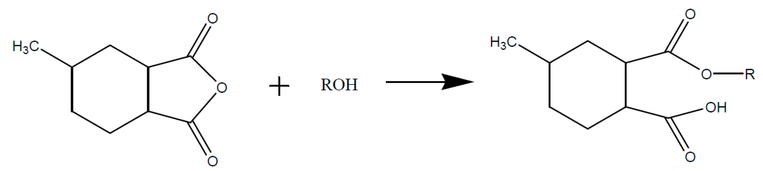
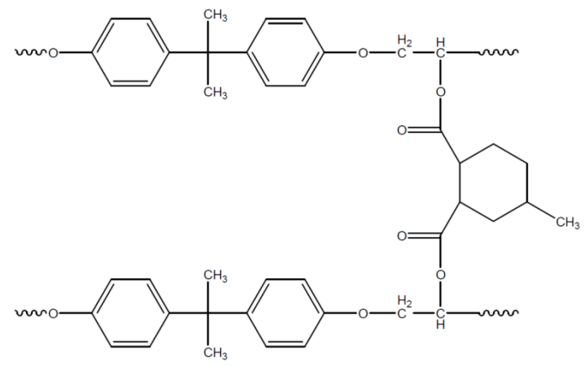
6. Epoxy Resins as Binder for Insulation Composites
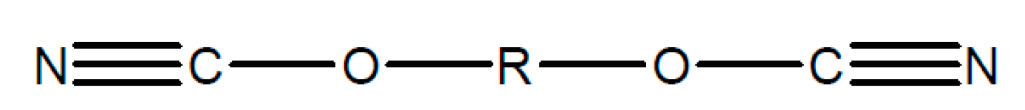
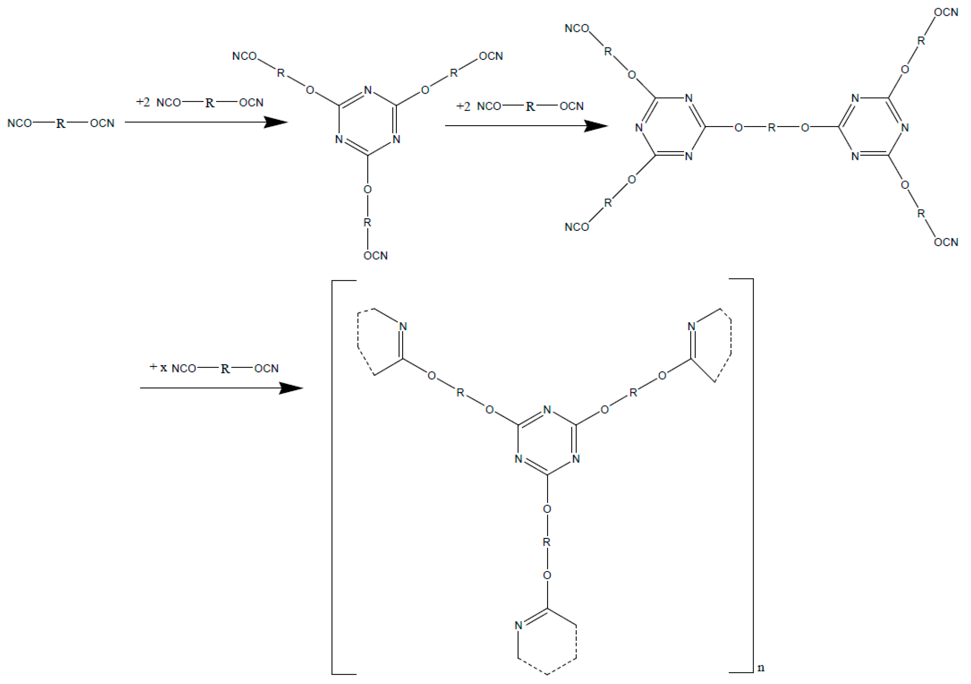
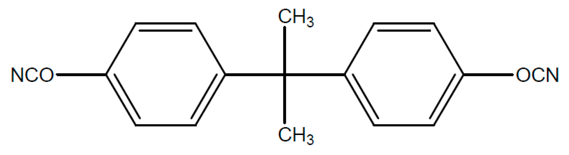
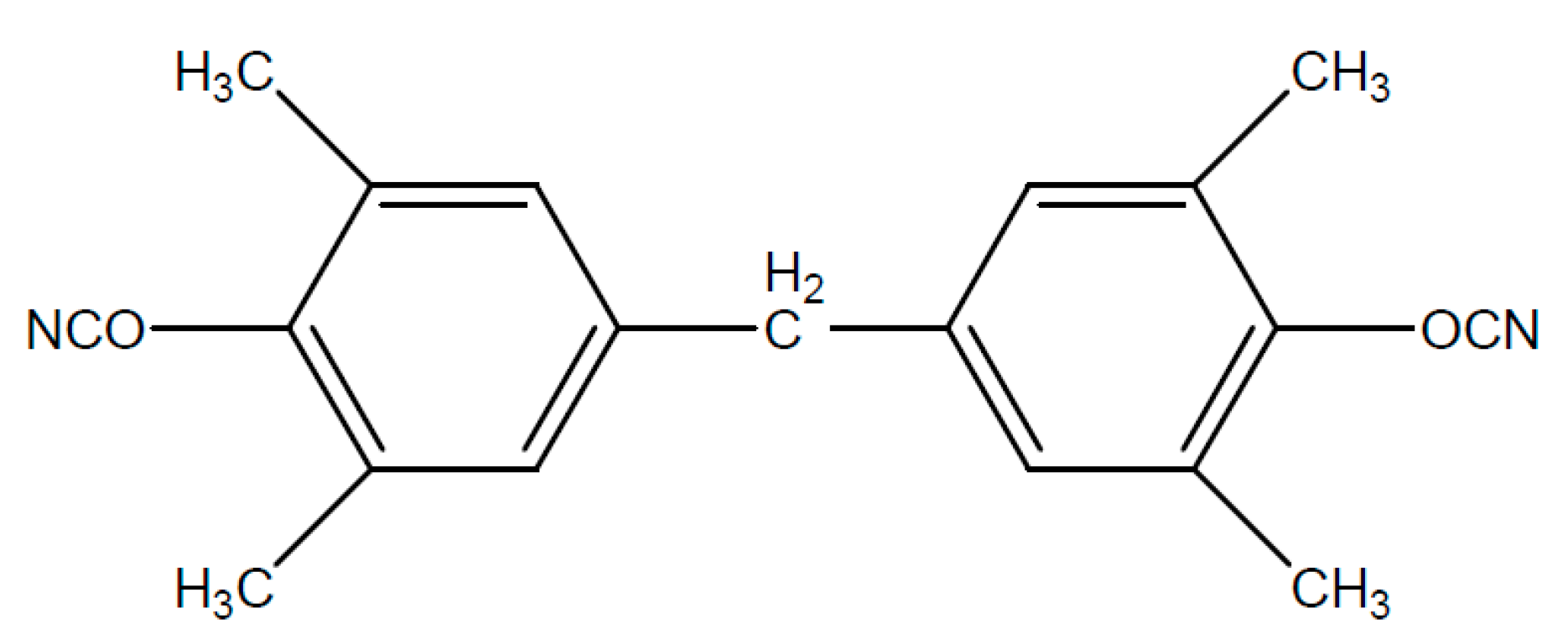
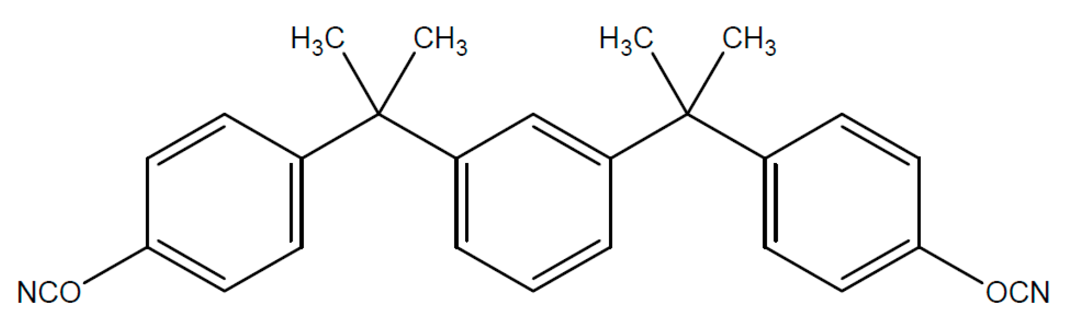
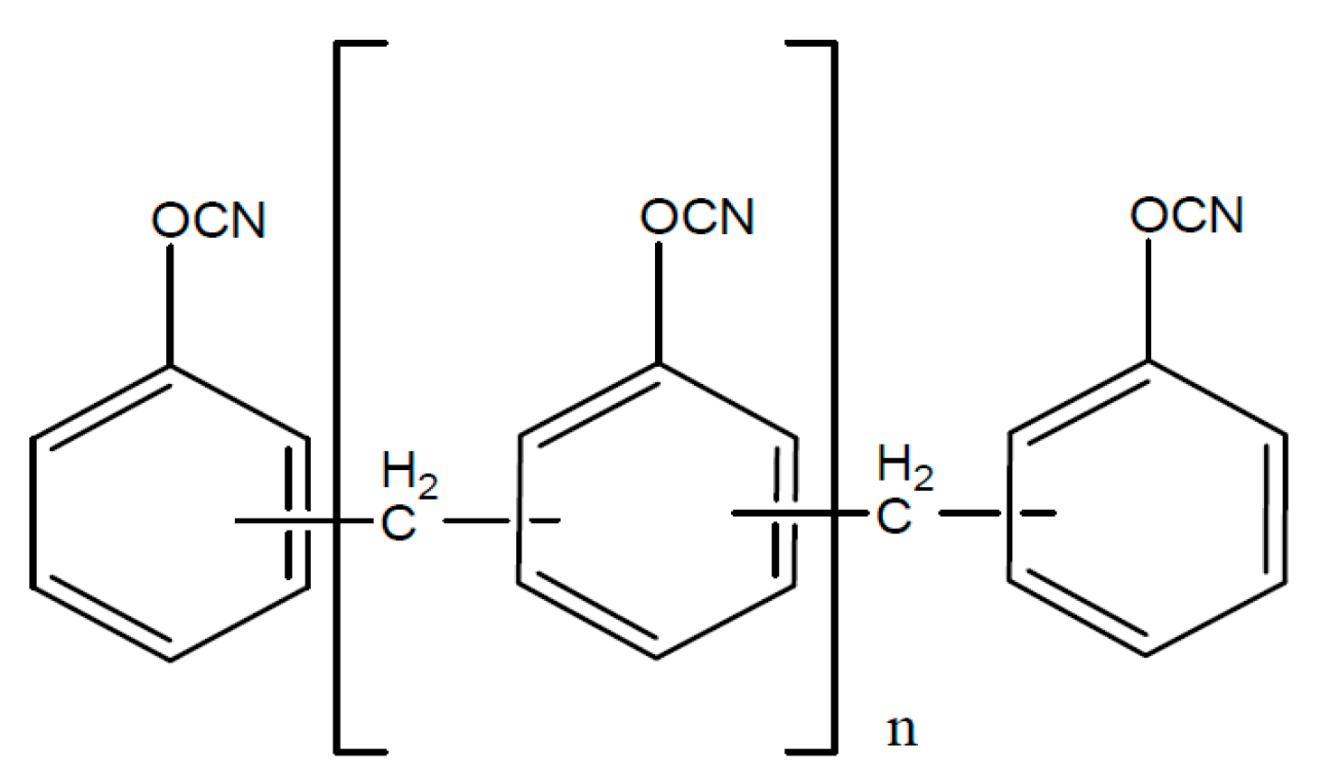
7. Alternative Resins as Binder Materials (Cyanate Resins)
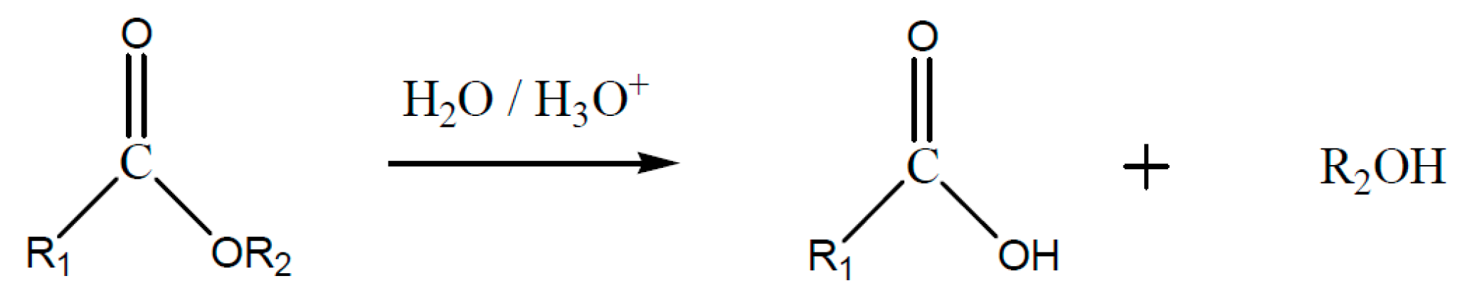
8. Temperature Resistance of Epoxy Resins
9. Final Review
Acknowledgments
Conflicts of Interest
References
- Brauns, R. Das Mineralreich; Fritz Lehmann-Verlag: Karlsruhe, Germany, 1903. [Google Scholar]
- Romdohr, P. Klockmanns Lehrbuch für Mineralogie; Ramdohr, P., Enke, H.S., Eds.; Verlag Thieme: Stutgart, Germany, 1978. [Google Scholar]
- Von Maegdefrau, E.; Hofmann, U.U. Glimmerartige Mineralien als Tonsubstanzen. Available online: http://www.degruyter.com/dg/viewarticle.fullcontentlink:pdfeventlink/$002fj$002fzkri.1938.98.issue-1-6$002fzkri.1938.98.1.31$002fzkri.1938.98.1.31.pdf?t:ac=j$002fzkri.1938.98.issue-1-6$002fzkri.1938.98.1.31$002fzkri.1938.98.1.31.xml (accessed on 31 March 2016).
- Hartmann, M. Über die Bauwürdigkeit von Pegmatitvorkommen auf Glimmer; Montan-Verlag: Düsseldorf, Germany, 1954; pp. 84–86. [Google Scholar]
- Rieder, M.; Cavazzini, G.; D‘Yakonov, Y.S.; Frank-Kamenetskii, V.A.; Gottardi, G.; Guggenheim, S.; Koval, P.V.; Müller, G.; Neiva, A.M.R.; Radoslovich, E.W.; et al. Nomenclature of the Micas; The Canadian Mineralogist: Vancouver, BC, Canada, 1998; Volume 36. [Google Scholar]
- Rotter, H.-W. Glimmer & Glimmererzeugnisse: Eigenschaften, Entwicklungen, Anwendungen; Siemens Aktiengesellschaft: Berlin, Germany, 1985; ISBN 3-8009-1451-4. [Google Scholar]
- Stevens, R.E. A system for calculatin analyses of micas and related minerals to end members. U.S. Geol. Surv. Bull. 1946, 950, 101–119. [Google Scholar]
- Foster, M.D. Interpretation of the compostition of trioctahedral micas. U.S. Geol. Surv. Prof. Pap. 1960, 354, 11–49. [Google Scholar]
- Rimsaite, J. Structural formulae of oxidized and hydroxyl-deficient micas and decompostition of the hydroxyl group. Contrib. Mineral. Petrol. 1970, 25, 225–240. [Google Scholar] [CrossRef]
- Schroeder, R. Glimmer und Glimmerprodukte. In Sonderausdruck Aus "Die Isolierstoffe der Elektrotechnik"; Schering, H., Ed.; Verlag von Julius Springer: Berlin, Germany, 1924. [Google Scholar]
- Mutschke, H. Glimmereigenschaften, Silikattechnik 19; Verlag von Julius Springer: Berlin, Germany, 1968. [Google Scholar]
- Helles, F. Wicklungen Elektrischer Maschinen; Verlag von Julius Springer: Berlin, Germany, 1936. [Google Scholar]
- Espe, W. Glimmer als Werkstoff der Hochvakuumtechnik; Veb Deutscher Verlag der Wissenschaften: Berlin, Germany, 1959. [Google Scholar]
- Mamdal, S.S.; Mahanti, P.C. Electrical properties of Indian mica. Indian J. Phys. Proc. Indian Assoc. Cultiv. Sci. 1953, XXVII, 294–304. [Google Scholar]
- Burmeister, H.C. Glimmerm, ein Werkstoff der Elektrotechnik, in Elektrotechnik Nr. 10; Montan-Verlag: Düsseldorf, Germany, 1985; pp. 64–68. [Google Scholar]
- Liebscher, F.; Held, W. Glimmer und Glimmererzeugnisse; Springer: Berlin, Germany, 1955. [Google Scholar]
- Rotter, H.W. Dauerverhalten von Isolierstoffen und Isoliersystemen; VDE-Verlag: Berlin, Germany, 1977; p. 757. [Google Scholar]
- Rotter, H.W. Thermidur, ein Isoliersystem für Extrem Hohe Temperaturen. In Siemens-Zeitschrift; VDE-Verlag: Berlin, Germany, 1929; pp. 299–301. [Google Scholar]
- Dawes, C.L.; Mansfield, W.R. Built-up mica plate for high-temperature applications. Electr. Eng. 1953, 72, 145–150. [Google Scholar] [CrossRef]
- R.I.S. Limited. Mica, 2nd ed.; R.I.S. Limited: London, UK, 1977. [Google Scholar]
- British Paint Research Association. Hochresistente Epoxy-Teerfarben mit Glimmerzusatz; Micafine Ltd.: Melton Mowbray, UK, 1962; p. 653. [Google Scholar]
- Schaumburg, H. Polymere: Mit 127 Tabellen und 328 formeln; Verlag-Teubner: Stuttgart, Germany, 1997. [Google Scholar]
- Brütsch, J.A.R. Selection and application of insulating materials: Their importance in VPI insulation for rotating machines. In Proceedings of the Coil Winding, Insulation & Electrical Manufacturing Conference, Berlin, Germany, 12–14 May 1998; pp. 137–144.
- Lenko, D.; Schlogl, S.; Bichler, S.; Lemesch, G.; Ramsauer, F.; Ladstätter, W.; Rosc, J.; Kern, W. New approaches towards the investigation on defects and failure mechanisms of insulating somposites used in high voltage applications. Compos. Part B 2013, 58, 83–90. [Google Scholar] [CrossRef]
- Hyundai Ideal Electric. Vacuum Pressure Impregnation (VPI) System. Available online: http://www.hyundaiideal.com/about/VPIPDF1.htm (accessed on 31 March 2016).
- Stone, G.C.; Culbert, E.B.; Dhirani, I.H. Stator Failure Mechanisms and Repair; Wiley-IEEE Press: Hoboken, NJ, USA, 2003. [Google Scholar]
- Stone, G.C.; Culbert, E.B.; Dhirani, I.H. Dhirani Electrical Insulation for Rotating Machines—Design, Evaluation, Aging, Testing and Repair; Wiley-IEEE Press: Hoboken, NJ, USA, 2003. [Google Scholar]
- Elektromotoren, V. Hochspannungsspulenfertigung Nach Dem resin-rich/VPI-Verfahren bei Vogelsang Elektromotoren. Available online: http://www.vogelsang.com/news/newsdetail/article/hochspannungsspulenfertigung-nach-dem-resin-rich-vpi-verfahren-bei-vogelsang-elektromotoren-in-boc.html (accessed on 31 March 2016).
- Vogelsang Elektromotoren. Drehmomente; Vogelsang Elektromotoren: Bochum, Germany, 2007. [Google Scholar]
- Schwab, A. HydroNews. In Magazin der Andritz Hydro; Andritz Hydro GmBH: Vienna, Austria, 2009. [Google Scholar]
- Vogelsang, R. Time to Breakdown of High Voltage Winding Insulations with Respect to Microscopic Properties and Manufacturing Qualities; Hartung-Gorre Verlag: Konstanz, Germany, 2004. [Google Scholar]
- Kimura, K. Progress of insulation aging and diagnostics of high voltage rotating machine windings in Japan. IEEE Electr. Insul. Mag. 1993, 3, 13–20. [Google Scholar] [CrossRef]
- Kimura, K.; Kaneda, Y. The role of microscopic defects in multistress aging of micaceous insulation. IEEE Trans. Dielect. Electr. Insul. 1995, 2, 426–432. [Google Scholar] [CrossRef]
- Stone, G.C.; Gupta, B.K.; Lyles, J.F.; Sedding, H.G. Experience with accelerating aging tests on stator bars and coils. In Proceedings of the Conference Record of the 1990 IEEE International Symposium on Electrical Insulation, Toronto, ON, USA, 3–6 June 1990; pp. 356–360.
- Kheirmand, A.; Leijon, M.; Gubanski, S.M. New practices for partial discharge detection and localization in large rotating machines. IEEE Trans. Dielectr. Electr. Insul. 2003, 10, 1042–1052. [Google Scholar] [CrossRef]
- Anders, G.J.; E, J.; Ford, G.L.; Stone, G.C. A probabilistic model for evcaluating the remaingin life of evaluating the remaining life of electrical insulation in rotating machines. IEEE Trans. Energy Convers. 1990, 5, 761–767. [Google Scholar] [CrossRef]
- Vogelsang, R.; Fruth, B.; Ducry, O. Performance testing of high voltage generator- and motor insulation systems. In Proceedings of the WSEAS International Conferences, Tenerife, Spain, 16–18 December 2005.
- Cheng, X.; Cheng, Y.; Yue, B.; Xie, H. Study of epoxy/Mica insulation deterioration in generator stator using ultra-wide band partial discharge testing technique. Polym. Test 2006, 2006, 724–730. [Google Scholar] [CrossRef]
- Van Breen, H.J.; Gulski, E.; Smit, J.J. Several aspects of stator insulation condition based maintenance. In Proceedings of the Conference record of the 2004 IEEE International Sypmosium on Electrical Insulation, Indianapolis, IN, USA, 19–22 September 2004; pp. 446–449.
- North American Electric Reliability Council (NERC). Available online: https://www.eeh.ee.ethz.ch/uploads/tx_ethpublications/Froehlich_Insulation_Failure_Mechanism_of_Power_Generators__IEEE_Electrical_Insulation_Magazine.pdf (accessed on 31 March 2016).
- Evans, D.L. IEEE Trans. on Power Apparatus and Systems PAS-100; IEEE: Piscataway, NJ, USA, 1981; pp. 3284–3293. [Google Scholar]
- Zwicknagl, W. Oesterreichischer verband der elektrotechnik. J. Elektrotech. Masch. 1998, 98, 221. [Google Scholar]
- Bomba, R.; Gross, U.; Kaiser, J. VGB data base generator damage cases. VGB PowerTech. 2005, 11, 87–92. [Google Scholar]
- Greg, C.; Stone, E.B.; Culbert, I.; Dhirani, H. Electrical insulation for rotating machines—Design, evaluation, aging, testing, and repair—Book review. IEEE Electr. Insul. Mag. 2004, 20, 65. [Google Scholar]
- CIGRE Study Committee SC11. Hydronenerator Failures—Results of the Survey; CIGRE Study Committee SC11: Paris, France, 2003. [Google Scholar]
- Bruetsch, R.; Tari, M.; Froehlich, K.; Weiers, T.; Vogelsang, R. Insulation failure mechanisms of power generators. IEEE Electr. Insul. Mag. 2008, 24, 17–25. [Google Scholar] [CrossRef]
- Zhidong, J.; Hao, Y.; Hengkun, X. The degradation assessment of epoxy/mica insulation under multi-stresses aging. IEEE Trans. Dielect. Eletr. Insul. 2006, 13, 415–422. [Google Scholar] [CrossRef]
- Srinivas, M.B.; Ramu, T.S. Multifactor aging of HV generator stator insulation including mechanical vibrations. IEEE Trans. Elect. Insul. 1992, 27, 1009–1021. [Google Scholar] [CrossRef]
- Rusu-Zagar, C.; Notingher, P.V.; Stancu, C. Aging and degradation of electrical machines insulation. J. Int. Sci. Publ. Mater. Methods Technol. 2014, 8, 526–546. [Google Scholar]
- Nothinger, P.V. Insulation Systems; PRINTECH House Ltd.: Bucharest, Romania, 2002. [Google Scholar]
- Nothinger, P.P. Accelerated development of electrical trees. Part I: Initiation of trees. Electr. Eng. Electron. Autom. 2009, 57, 1–19. [Google Scholar]
- Fothergill, J.C. Ageing, Space Charge and Nanodielectrics: Ten Things We Don’t Know About Dielectrics. In Proceedings of the International Conference on Solid Dielechtrics, Winchester, UK, July 8–13 2007; pp. 1–10.
- Amyot, N.; Lévesque, M.; Bélec, M.; Brabant, F.; Frenette, F.X. A new prognostic approach for hydrogenerator stator windings. In Proceedings of the Annual Conference of the Prognostics and Health Management Society, Gaithersburg, MD, USA, 24–27 June 2013.
- Yue, B.; Zhelei, Z.; Xiaolin, C.; Xie, H. Study on the characteristic parameters used to assess the insulation condition of stator windings. In Proceedings of the Seventh International Conference on Properties and Applications of Dielectric Materials, Rome, Italy, 1–5 June 2003.
- Yue, B.; Jian, L.; Zhang, X.; Yonghong, C. Using AC current parameters to assess aging condition of epoxy/mica insulaion. In Proceedings of the International Symposium on Electrical Insulation Materials, Himeji, Japan, 19–22 November 2001.
- Stone, G.C.; Sedding, H.G.; Lloyd, B.A.; Gupta, B.K. The ability of diagnostic tests to estimate the remaining life of stator insulation. IEEE Trans. Energy Convers. 1988, 3, 833–841. [Google Scholar] [CrossRef]
- Wichmann, A.; Grunewald, P.; Weidner, J. Betriebliche Einflussgrössen auf die elektrische Lebensdauer von Hochspannungsisolierungen in Turbogeneratoren; ETG Fachberichte: Hannover, Germany, 1985; Volume 16, pp. 44–48. [Google Scholar]
- Kimura, K.; Kaneda, Y. Breakdown voltage and observation on mica insulation systems after thermal aging and mechanical fatigue. In Proceedings of the 7th Intnational Symposium on High voltage Engineering, Dresden, Germany, 26–30 August 1991.
- Lee, S.M. Electrical and Electronic Applications; Marcel Dekker Inc: New York, NY, USA, 1988; pp. 783–884. [Google Scholar]
- May, C.A. Epoxy Resins, Chemistry and Technology; Marcel Dekker: New York, NY, USA, 1988. [Google Scholar]
- Boey, F.Y.C.; Qiang, W. Experimental modeling of the cure kinetics of an epoxyhexahydro-4-methylphtalicanhydride (MHHPA) system. Polymer 2000, 41, 2081–2094. [Google Scholar] [CrossRef]
- Liu, Y.; Du, Z.; Zhang, C.; Li, C.; Li, H. Curing behavior and thermal properties of multifunctional epoxy resin with methylhexahydrophtalic anhydride. J. Appl. Polym. Sci. 2007, 103, 2041–2048. [Google Scholar] [CrossRef]
- Hamerton, L.; Howlin, B.J.; Jepson, P. Metals and coordination compounds as modifiers for epoxy resins. Coord. Chem. Rev. 2002, 224, 67–85. [Google Scholar] [CrossRef]
- Smith, J.D.B. Metal acetylacetonates as latent accelerators for anhydride-cured epoxyresins. J. Appl. Poly. Sci. 1981, 26, 979–986. [Google Scholar] [CrossRef]
- Schmidlin, B. Verfahren zur Herstelluing von Imprägnierbaren Feinglimmerbänder mit Eingebautem Beschleuniger. Europa Patent O 194974, 27 April 2000. [Google Scholar]
- Neville, L.J.; Neville, K. Industrial Motors Users Handbook of Insulation for Rewinds; Elsevier Science Ltd: Amsterdam, The Netherlands, 1977. [Google Scholar]
- Grimsley, B.W.; Pascal, H.; Song, X.; Cano, R.J.; Loos, A.C.; Pipes, R.B. Effects of amine and anhydride curing agents on the VARTM matrix processing properties; The National Aeronautics and Space Administration (NASA): Washington, DC, USA, 2002.
- Shen, S.; Li, Y.; Gao, J.; Sun, H. Curing kinetics and mechanism of bisphenol S epoxy resin with 4,4′-diaminodiphenyl ether or phthalic anhydride. Int. J. Chem. Kinet. 2001, 33, 558–563. [Google Scholar] [CrossRef]
- Blank, W.J.; Hu, Z.A.; Picci, M. Catalysis of the Epoxy-Carboxyl Reaktion, I; Waterborne: New Orleans, LA, USA, 2001. [Google Scholar]
- Han, J.; Wood, B.; Herman, H.; Stevens, G.C. Cure kinetics for bisphenol A resin with zinc naphthanate accelerator. In Proceedings of the Conference Record of the 2010 IEEE International Symposium on Electrical Insulation (ISEI), San Diego, CA, USA, 6–9 June 2010.
- Stabile, S.J. Extension of the post impregnation concept to high voltage windings. In Proceedings of the 11th Electrical Insulation Conference, New York, NY, USA, 30 September 1973.
- Mertens, W.; Meyer, H.; Wichmann, A. Micalastic-insulation experience and progress. In Proceedings of the Seventh Electrical Insulation Conference, Chicago, IL, USA, 16 October 1967.
- Kimura, H.; Ohtsuka, K.; Matsumoto, A. Curing reaction of bisphenol-A based benzoxazine with cyanate ester adn the properties of the cured thermosetting resin. eXPRESS Polym. Lett. 2011, 5, 1113–1122. [Google Scholar] [CrossRef]
- Prokopec, R.; Humer, K.; Fillunger, H.; Maix, R.K.; Weber, H. Mechanical behaiviour of cyanate ester/epoxy blends after reactor irradiation to high neutron fluences. In Advanced in Cryogenic Engineering; American Institute of Physics: Melville, NY, USA, 2008; pp. 182–189. [Google Scholar]
- Hamerton, I. Chemistry and Technology of Cyanate Ester Resins; Chapman and Hall: London, UK, 1994. [Google Scholar]
- Ehrenstein, G.W.; Pongratz, S. Beständigkeit von Kunststoffen; Carl Hanser Verlag GmbH & Co. KG: Munich, Germany, 2007. [Google Scholar]
- Führer, R. Weiterentwicklung und Impementierung eines Isolationssystems der Temperaturklasse H für Hochspannungs-Anwendungen. In Lehrstuhl für Chemie der Kunststoffe; Montan Universität Leoben: Leoben, Austria, 2013. [Google Scholar]
- Brütsch, T.H. High Voltage Stator Insulation; European Electrical Insulation Manufacturers: Reutlingen, Germany, 2005. [Google Scholar]
- Jain, R.; Choudhary, V.; NArula, A.K. Curing and thermal behavior of DGEBA in presence of dianhydrides and aromatic diamine. J. Appl. Polym. Sci. 2007, 105, 3802–3808. [Google Scholar] [CrossRef]
- Boulter, E.A.; Stone, G.C. Historical development of rotor and stator winding insulation materials and systems. IEEE Electr. Insul. Mag. 2007, 105, 25–39. [Google Scholar] [CrossRef]
- Mertens, W. Method of Producing an Insulating Sleeve of Mica Tape Impregnated with Thermosetting Epoxide Impregnating Resin Mixtureand Product Thereof. US 3556925 A, 19 January 1971. [Google Scholar]
- Chian, W. Chemical/mechanical analyses of anhydride-cured thermosetting epoxys: DGEBA/NMA/BDMA. Macromolecules 2004, 37, 8098–9109. [Google Scholar] [CrossRef]
- Koreeda, T.; Matos, J. Thermal characterization of mica-epoxy composite used as insulation material for high voltage machines. J. Therm. Anal. Calorim. 2001, 106, 619–623. [Google Scholar] [CrossRef]


| Properties | Unit | Muscovite | Phlogopite |
|---|---|---|---|
| Thermal properties | |||
| Melting temperature | °C | 1,200 to 1300 | 1,200 to 1,300 |
| Start of Calcination | °C | 550 to 650 | 750 to 900 |
| Long term thermal stability | °C | 500 | 700 |
| Thermal conductivity | W/m·K | 0.25 to 0.75 | ca. 1.7 |
| Coefficient of thermal expansion | K−1 | 90 × 10−7 | 135 × 10−7 |
| Specific heat | J/g·K | 0.06 | 0.26 |
| Flammability | inflammable | inflammable | |
| Mechanical properties | |||
| Density | g/cm3 | 2.6 to 3.1 | 2.6 to 3.2 |
| Hardness (acc. to mobs) | N/mm2 | 2.8 to 3.2 | 2.5 to 2.7 |
| Compressive strength | N/mm2 | 200 to 400 | 150 to 300 |
| Shear strength | N/mm2 | 250 | 110 |
| E-module (d = 250 µm) | N/mm2 | 180 × 10−3 | 170 × 10−3 |
| Electrical properties | |||
| Permittivity | ε | 6 to 8 | 5 to 6 |
| Dielectric loss factor (tan α) | 3 × 10⁻⁴ (106 Hz) | 10 to 100 × 10−4 | |
| Dielectric strength (20 °C, 50 Hz) | KV/mm | 60 to 70 (up to 1 mm) | 50 (up to 1 mm) |
| Resistance to tracking | KB-wert | >600 | >600 |
| Corona resistance | corona resistant | corona resistant | |
| Other physical/chemical properties | |||
| Refractive number | 1.56 to 1.61 | 1.58 to 1.61 | |
| Radiation resistance | very good | very good | |
| Resistance against organic solvents | resistant | resistant | |
| Acid resistance | resistant (except hydrofluoric acid) | resistant (except hot acids) | |
| Oil resistance | resistant | resistant | |
| Color | reddish ,green, colorless, brown | amber, green | |
| Physiological effect | no precautionary measures, harmless | ||
| Amount of crystal bonded water % | 4.5 | 3 |
| Application/Devices | Example of usage |
|---|---|
| electrical devices | inductor of voltmeters, commutators, power inverters, high voltage commutators, rotating field coils, high voltage transformers, heat traps |
| radio receiver, TV, radar | solid state systems, condensers, tubes, microwave windows, transistor shielding |
| electrical light devices | arc lamps, huge incandescent lamps, bases for lampshades, neon lamps, dimmer counters, turn signal systems |
| mixed electric applications | fuse cover platelets, spark plugs for high compression engines, sealing shims, insulators |
| electrical household appliances | coffee machines, cigar lighters, hair roller, irons, immersion heaters, permanent wave devices, toasters, vibrators, space heaters, hair dryer, waffle iron |
| electrical monitoring systems | grid resistors, pyrometer, relays, electrical and thermal controller |
| mechanical applications | dials, membranes for acoustic instruments, heart-lung-machines, respirators, gaskets for high temperature measurement instruments, lantern windows, fireplaces, unbreakable safety goggles, quarter-wave-plates for optical instruments, vision panels in ovens, synthetic, optical crystals |
| industrial electrical applications | corrugated rolls, glue pots, lead baths, devices for local warming, several heating elements, soldering irons, thermostats |
| VPI | Resin rich | ||
|---|---|---|---|
| With heated molds | With asphalt pressure molding | ||
| Strand insulation—dielectric strength | negligible difference between systems | ||
| Insulation tape | mica paper with glass fabric carrier and without resin | mica paper with resin and glass carrier | mica paper with resin and glass carrier |
| Number of insulation layers | depending on rated voltage no appreciable difference between systems | ||
| Internal potential grading for optimized field distribution in the main insulation | yes | multiturn coils—no Stator bars—yes | yes |
| Corona protection with tapes | yes | yes | yes |
| Vacuum impregnation with epoxy resin | yes | yes | yes—resin pre-loaded in tapes |
| Winding overhang section of bar | winding overhang and slot section—same materials | winding overhang and slot section—different material for coils only to improve windability | winding overhang and slot section—same materials |
| Composition of main insulation Mica content Glass content Resin content | approx. 65% approx. 10% approx. 25% | approx. 65% approx. 10% approx. 25% | |
| Main insulation dielectric strength | negligible difference between systems | ||
| Partial Discharges within the insulation (PD level) | very low, no micro voids; PD/single bar lower than 2 nC | pressed—slightly higher due to lack of vacuum | very low, no micro voids; PD/single bar lower than 2 nC |
| Advantages | void-free insulation by removal of air through the vacuum process-penetration of impregnating resin into the insulation to fill the voids, minimization of corona activity, achieve very low levels of PD, high temperature capability | low viscosity resin during heating results in very few retained voids, insulation system results in very high dielectric strength, ow PD system, high temperature capability | void-free insulation by removal of air through the vacuum process, presence of pre-impregnated tapes ensures maximum void fill particularly near bare bar, achieve extremely low levels of PD, high temperature capability |
| Process/Characteristic | Breakdown | Degradation | Aging |
|---|---|---|---|
| Evidence | direct observation (normally by eye-hole through insulation) | observable directly (may require microscopic or chemical techniques) | difficult to observe (may even be difficult to prove existence) |
| Place | continuous filament | occurs in weak parts | assumed to occur throughout insulation |
| Size | < mm (dependent on energy of event) | <µm (may form larger structures) | <nm (molecular scale) |
| Speed | fast (occurs in <<1 s) | less than required service life (hours—years) | continuous process (whole service life) |
| Effect | catastrophic (insulation cannot be used afterwards) | leads to breakdown (reduces breakdown voltage) | may lead to degradation (may not reduce breakdown voltage) |
| Examples | thermal, electromechanical, mixed mode, avalanche, intrinsic | partial discharges, electrical trees, electrochemical trees | bond scissions, nano voids, trap formation, non-electrical changes (oxidation etc.) |
| Types of process | Number of physical states |
|---|---|
| Thermal (t) | 9 |
| Electrical (e) | 22 |
| Ambient (a) | 14 |
| Mechanical (m) | 35 |
| Root causes per stress category | Number of failure mechanisms |
|---|---|
| Thermal Stress (T) | 8 |
| T1 thermal aging (normal operation) | 3 |
| T2 accelerated aging (operation above specified rated temperatures) | 3 |
| T3 aging due to thermal cycling (frequent start/stop operation) | 2 |
| Electrical Stress (E) | 8 |
| E1 improper manufacturing or design of bars | 2 |
| E2 poor semiconducting coating on the straight part of the bars (slot discharges) | 1 |
| E3 poor design or manufacturing of end winding stress grading material (corona discharges) | 1 |
| E4 insufficient spacing between end windings (gap discharges) | 1 |
| E5 overvoltage transients | 3 |
| Ambient Stress (A) | 35 |
| A1 conducting contamination (carbon, steel or copper dust) | 6 |
| A2 non-conductive contamination (construction dust or oil) | 9 |
| A3 moisture in ambient air | 7 |
| A4 abrasive material attack | 3 |
| A5 water leakage (cooling system failure, fire protection and spills) | 10 |
| Mechanical Stress (M) | 60 |
| M1 loose windings | 17 |
| M2 bad connection | 6 |
| M3 presence of external objects or loose parts | 5 |
| M4 mechanical shocks | 4 |
| M5 Projectiles | 4 |
| M6 Rotor and/or stator deformation | 24 |
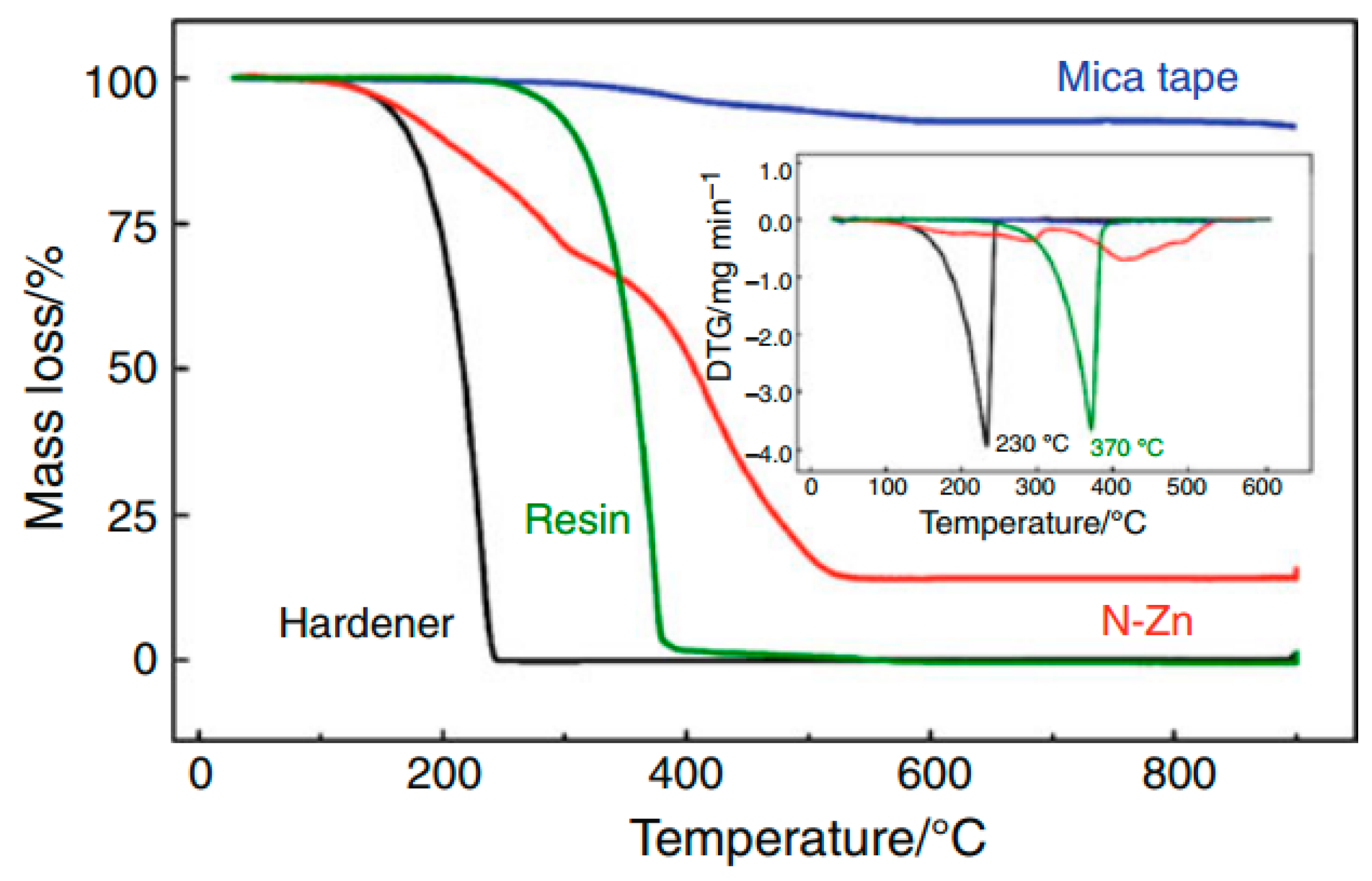
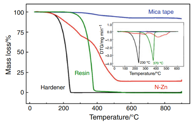
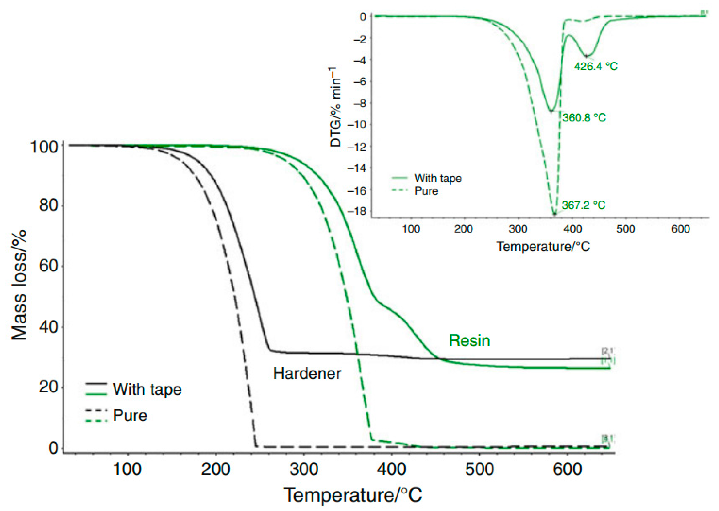
| Component | Degradation temperature (°C) | |
|---|---|---|
| Experimental | Literature | |
| Resin | 322 | >300 |
| Hardener | 207 | 203 |
| Mica tape | 348 | – |
| N–Zn | 251 | 250 |
© 2016 by the authors. Licensee MDPI, Basel, Switzerland. This article is an open access article distributed under the terms and conditions of the Creative Commons Attribution (CC-BY) license ( http://creativecommons.org/licenses/by/4.0/).
Share and Cite
Andraschek, N.; Wanner, A.J.; Ebner, C.; Riess, G. Mica/Epoxy-Composites in the Electrical Industry: Applications, Composites for Insulation, and Investigations on Failure Mechanisms for Prospective Optimizations. Polymers 2016, 8, 201. https://doi.org/10.3390/polym8050201
Andraschek N, Wanner AJ, Ebner C, Riess G. Mica/Epoxy-Composites in the Electrical Industry: Applications, Composites for Insulation, and Investigations on Failure Mechanisms for Prospective Optimizations. Polymers. 2016; 8(5):201. https://doi.org/10.3390/polym8050201
Chicago/Turabian StyleAndraschek, Natascha, Andrea Johanna Wanner, Catharina Ebner, and Gisbert Riess. 2016. "Mica/Epoxy-Composites in the Electrical Industry: Applications, Composites for Insulation, and Investigations on Failure Mechanisms for Prospective Optimizations" Polymers 8, no. 5: 201. https://doi.org/10.3390/polym8050201
APA StyleAndraschek, N., Wanner, A. J., Ebner, C., & Riess, G. (2016). Mica/Epoxy-Composites in the Electrical Industry: Applications, Composites for Insulation, and Investigations on Failure Mechanisms for Prospective Optimizations. Polymers, 8(5), 201. https://doi.org/10.3390/polym8050201