
Seismic Behavior of Substandard RC Columns Retrofitted with Embedded Aramid Fiber Reinforced Polymer (AFRP) Reinforcement


Abstract
:
1. Introduction

2. Experimental Program
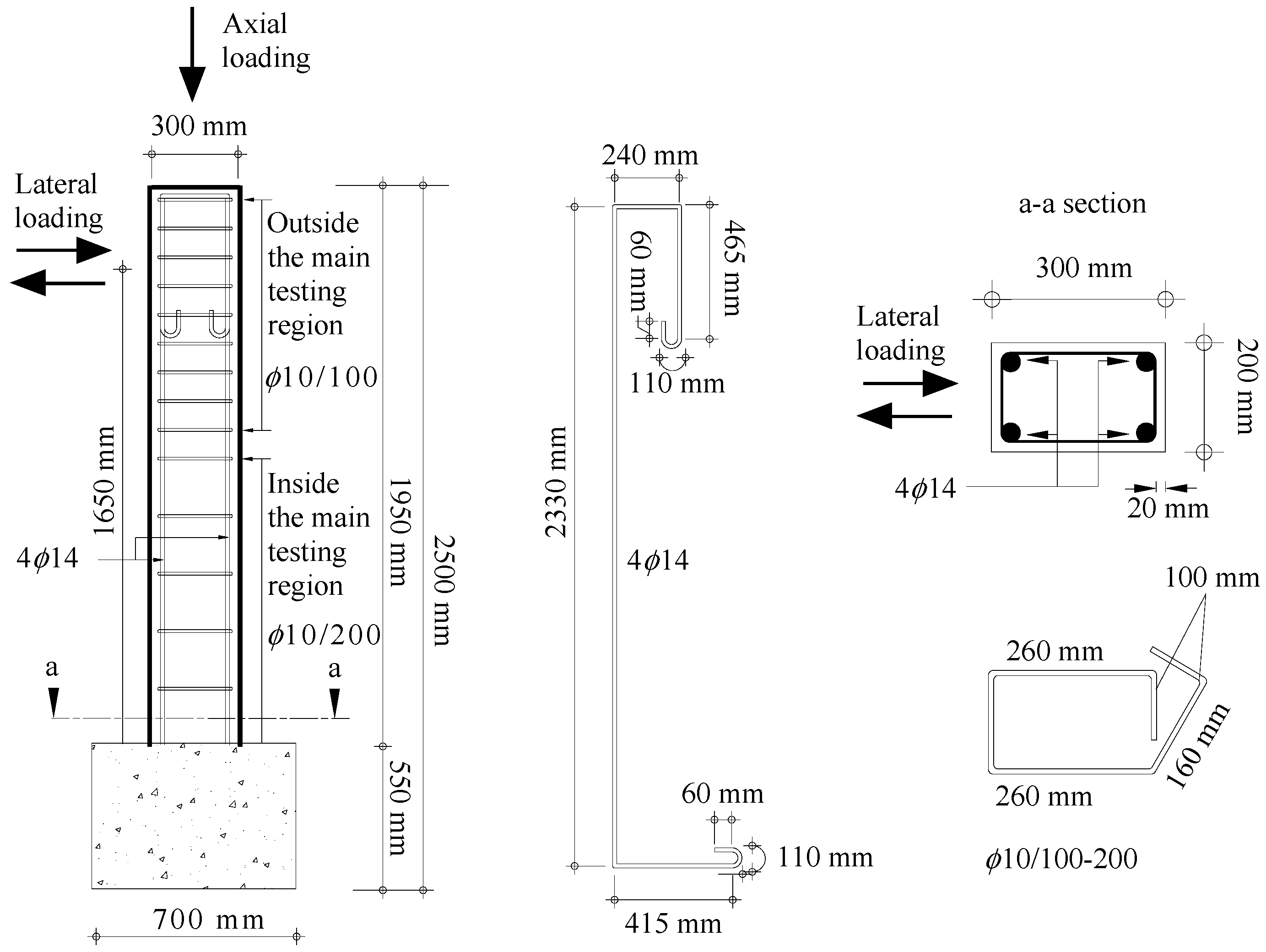
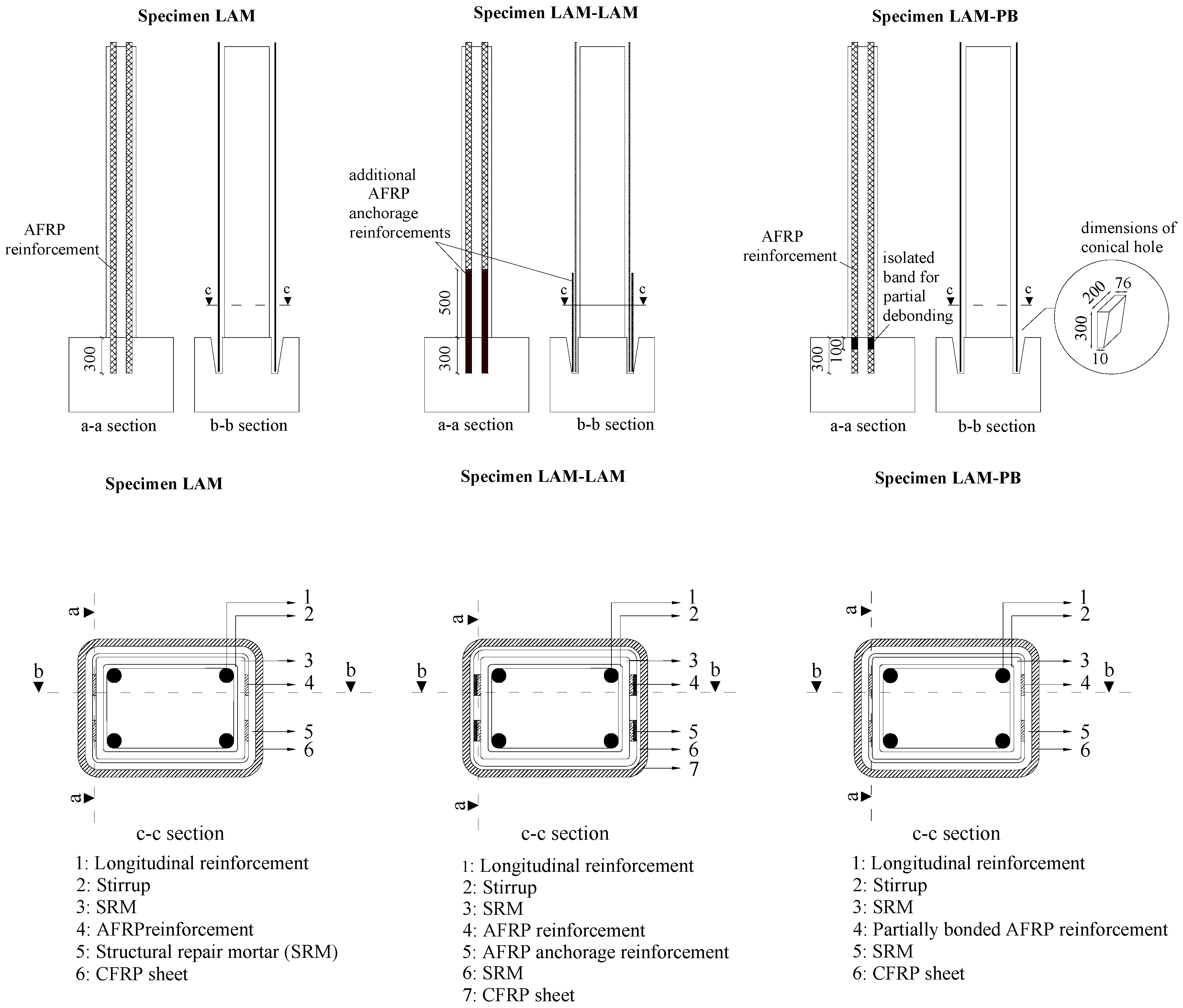
2.1. Description of Test Specimens

| Specimen | Main longitudinal AFRP a reinforcement | Additional anchorage reinforcement a | Anchorage type a | Transverse CFRP b reinforcement |
|---|---|---|---|---|
| REF | – | – | – | – |
| LAM | 2 × 2 (each 42 mm x 1.4 mm) | – | Fully bonded | 2 plies × 0.166 mm |
| LAM-PB | 2 × 2 (each 42 mm x 1.4 mm) | – | Partially bonded | 2 plies × 0.166 mm |
| LAM-LAM | 2 × 2 (each 42 mm × 1.4 mm) | 2 × 2 (each 42 mm × 1.4 mm) | Fully bonded | 2 plies × 0.166 mm |


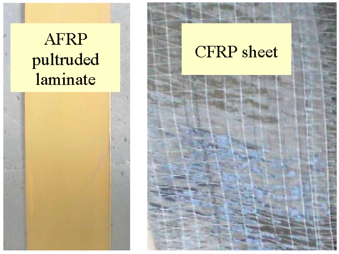
2.2. Characteristics of Materials
| FRP reinforcement | Ef (N/mm2) | tf (mm) | wf (mm) | εfu* |
|---|---|---|---|---|
| AFRP (laminate) | 60,000 | 1.4 | 42 | 0.023 |
| CFRP (sheet) | 230,000 | 0.166 | 500 | 0.015 |
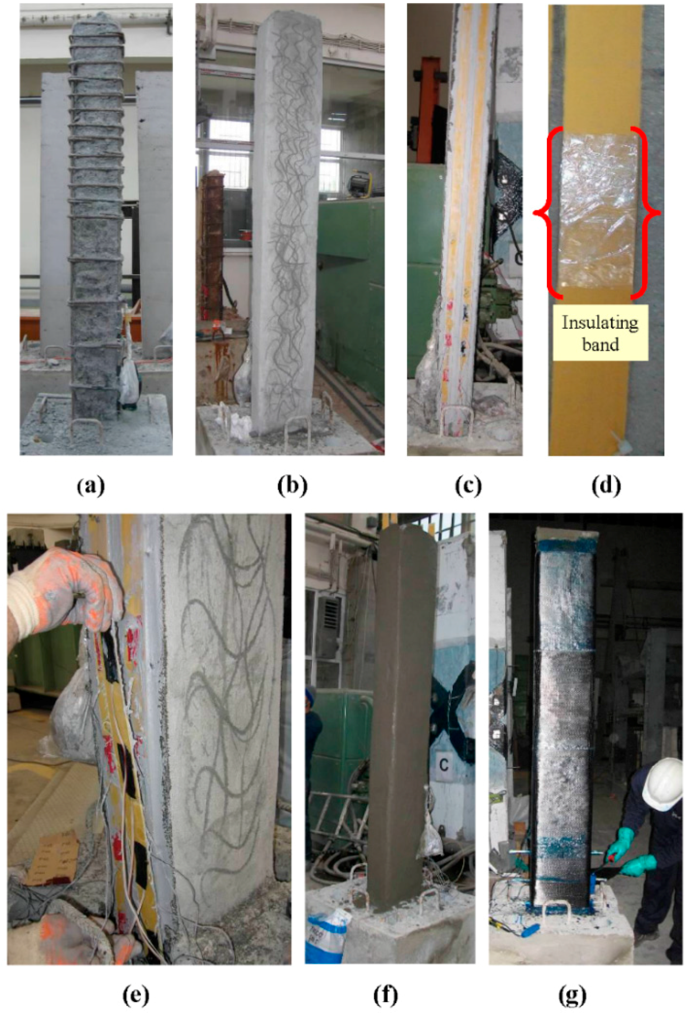
2.3. Retrofitting Procedure

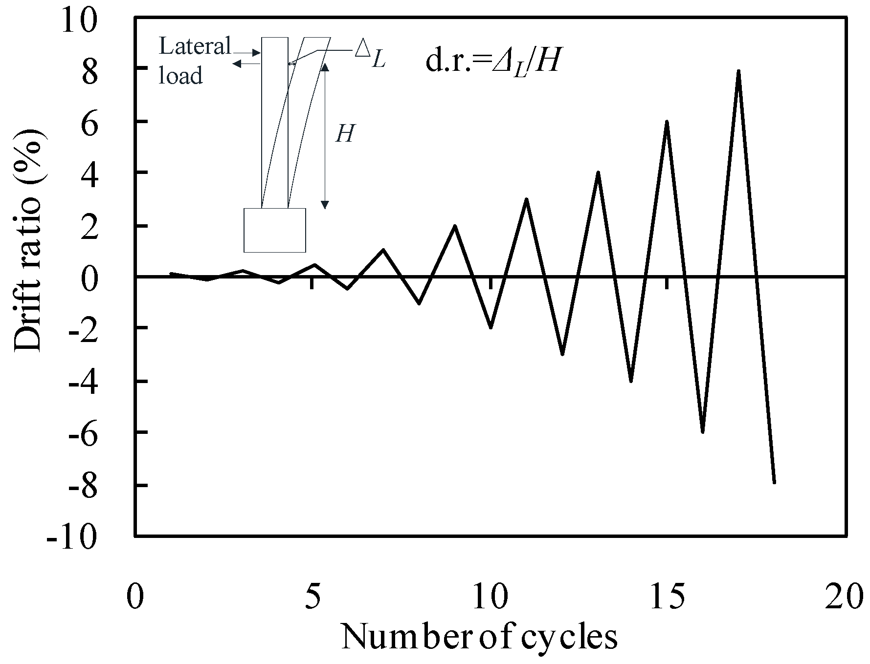
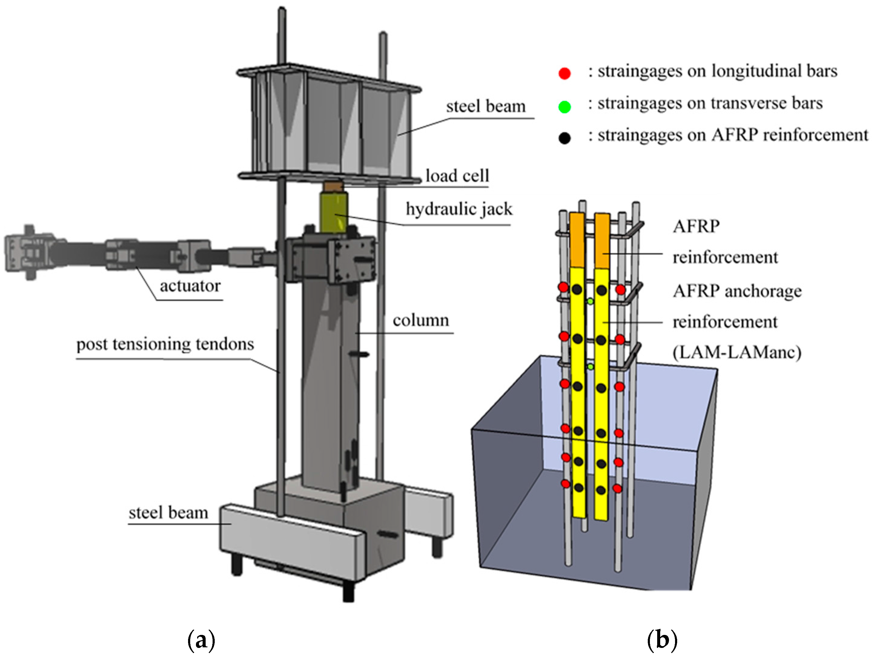
2.4. Test Setup


3. Analytical Considerations
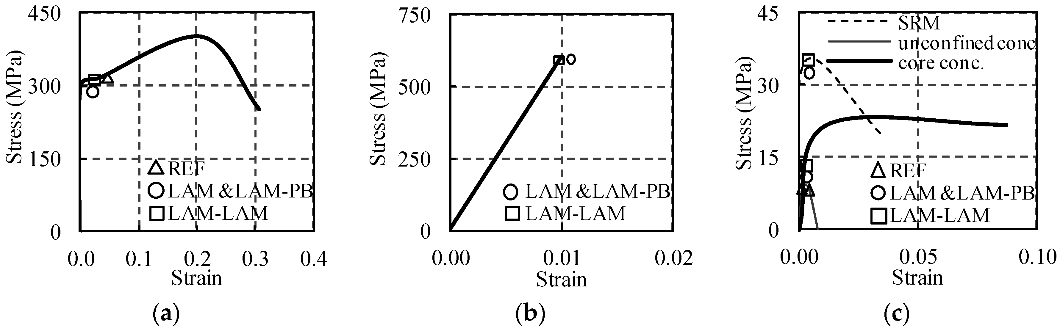
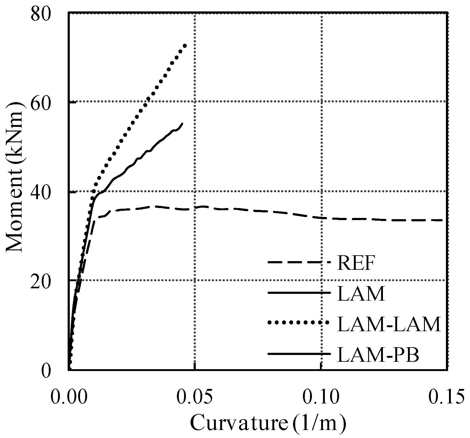
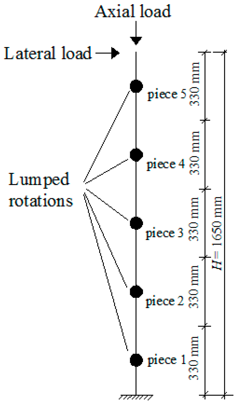
3.1. Theoretical Flexural Strength and Displacement Capacity before and after Retrofit


3.2. Shear Strength before and after Retrofit
| Specimens | REF | LAM and LAM-PB | LAM-LAM |
|---|---|---|---|
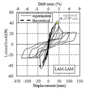
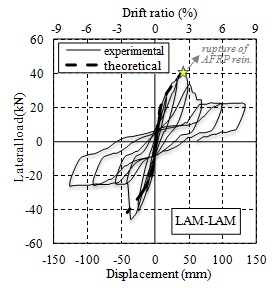
| Theoretical lateral load capacity (kN) | 21.2 | 32.1 | 41.8 |
| Experimental lateral load capacity (kN) | 24.5 | 33.8 (for the specimen LAM) 34.6 (for the specimen LAM-PB) | 45.1 |
| Theoretical moment capacity (M0) (kNm) | 36.5 | 55.0 | 72.4 |
| Theoretical failure mode | Y before C | Y, T | Y, then T |
| Observed failure mode | Y before C | Y, F | Y, FA |
| Shear strength (kN) | 108.0 (Vc+Vs) | 260.6 (Vc+Vs+ψf·Vf) | |
3.3. Anchorage Length for FRP Reinforcement in Footing
4. Results and Discussions
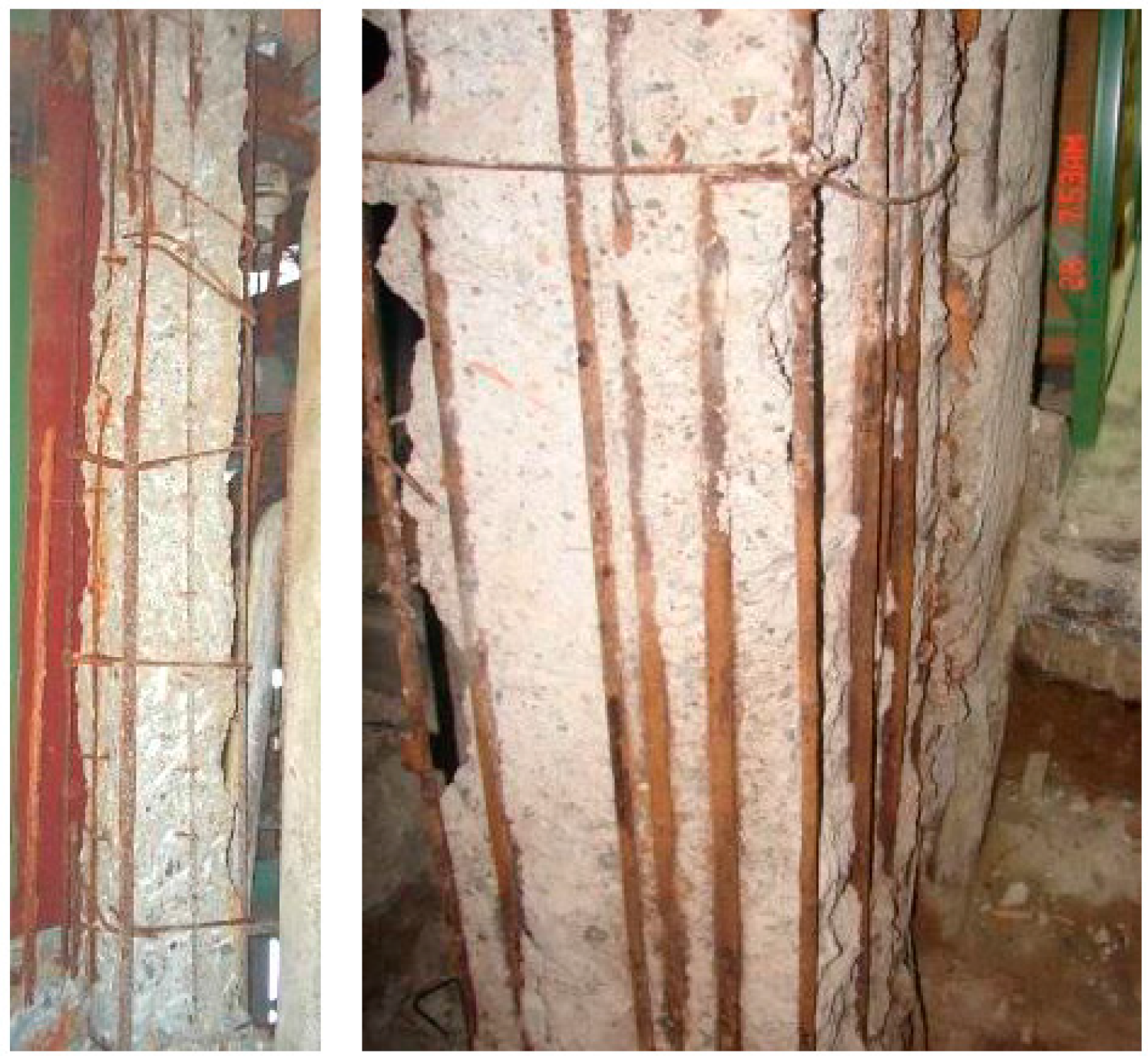
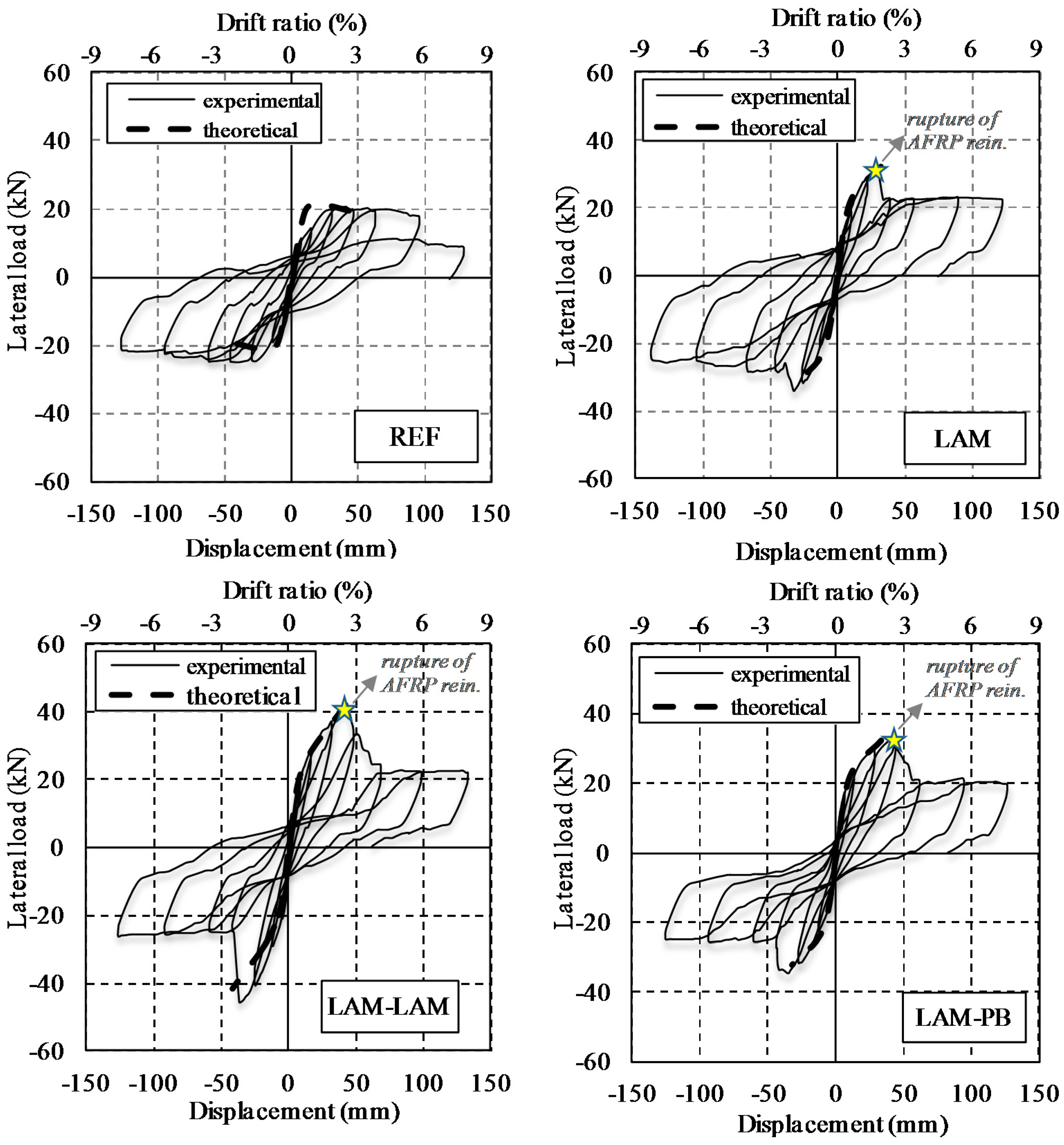
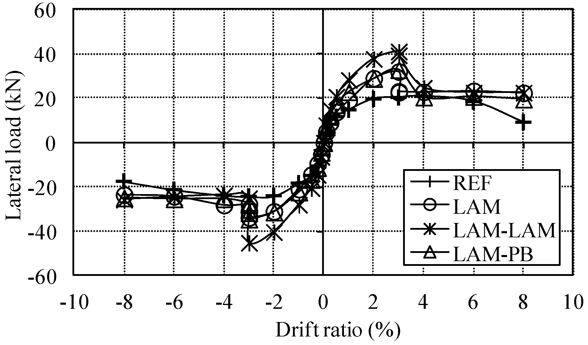
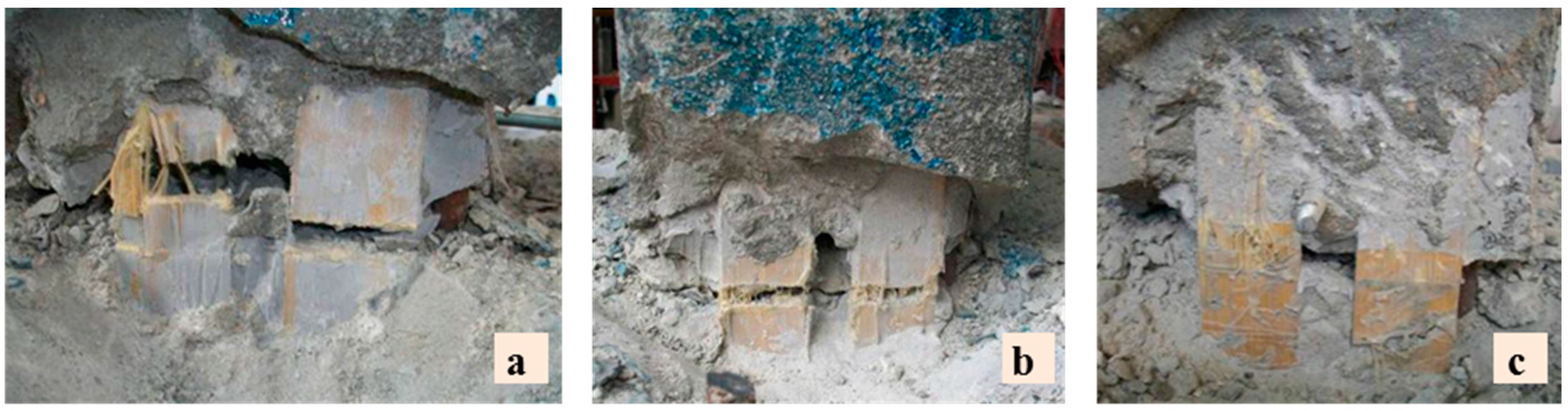
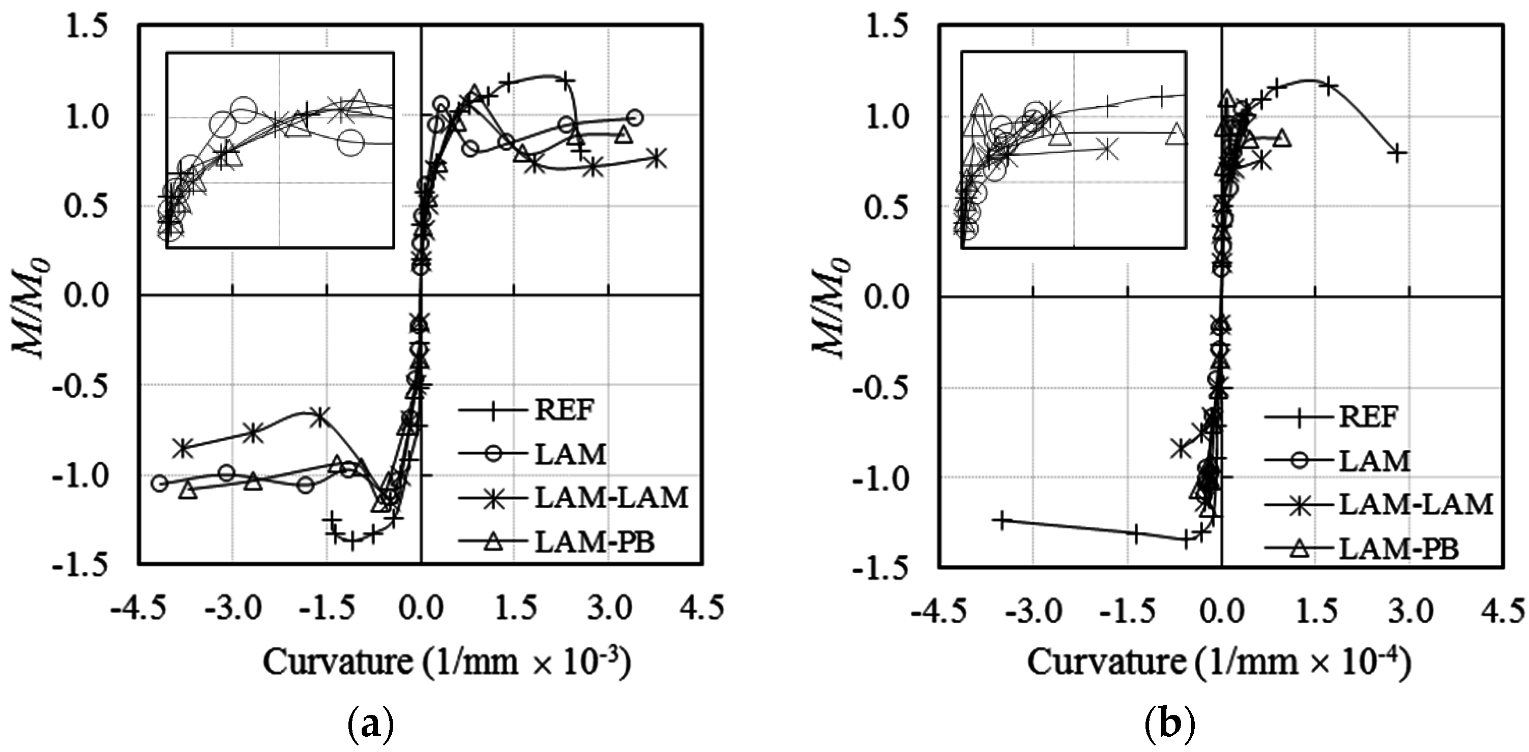
4.1. Lateral Load–Displacement Curves and Failure Modes


| Damage mechanisms | Specimens | |||
|---|---|---|---|---|
| REF | LAM | LAM-LAM | LAM-PB | |
| Yielding of longitudinal steel bars | 2 | 3 | 3 | 3 |
| Crushing of concrete cover | 3 | – | – | – |
| Spalling of concrete cover | −6 | – | – | – |
| Fracture of AFRP reinforcement | – | 3 | 3 | 3 |

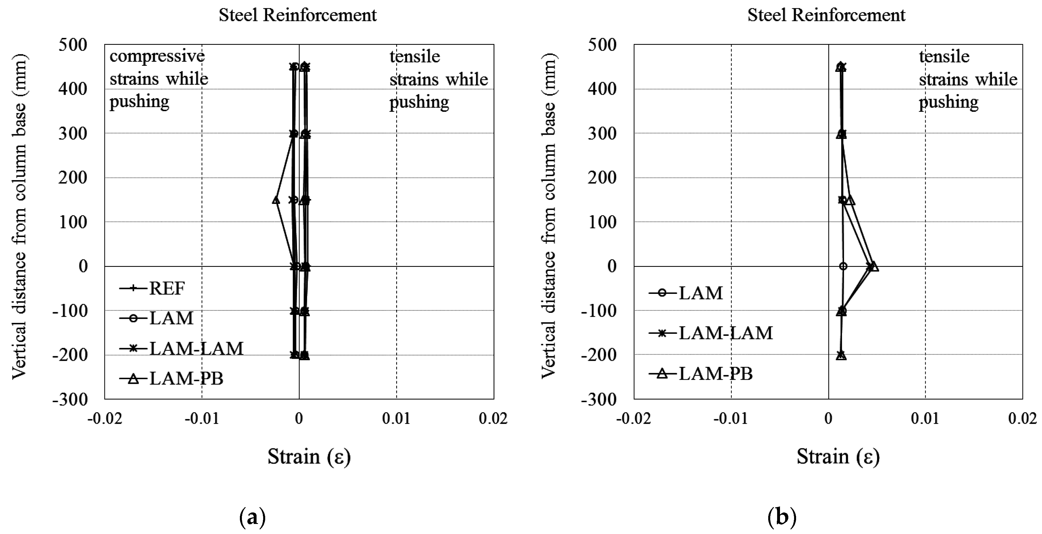
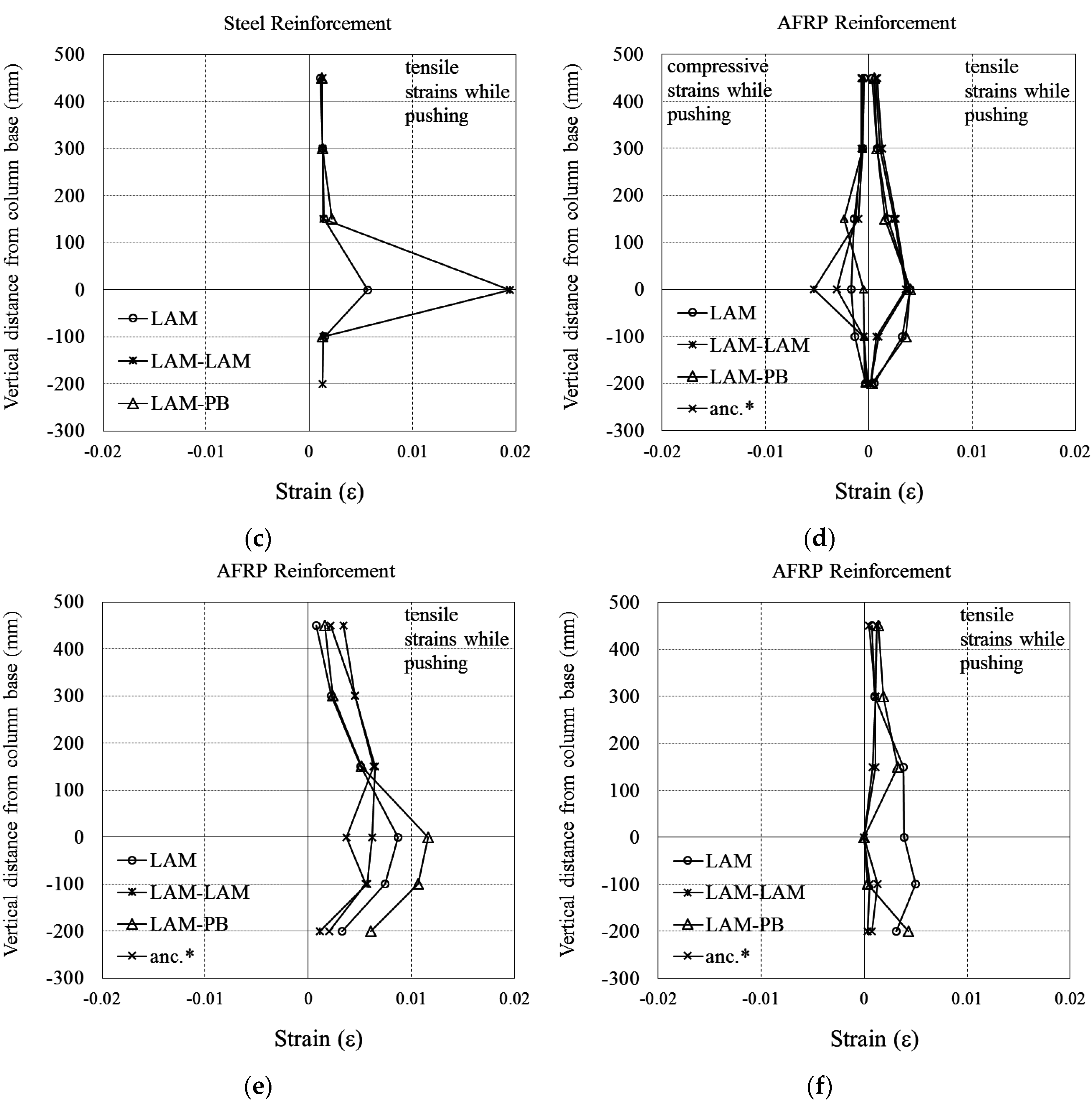
4.2. Strains of Steel and AFRP Reinforcement

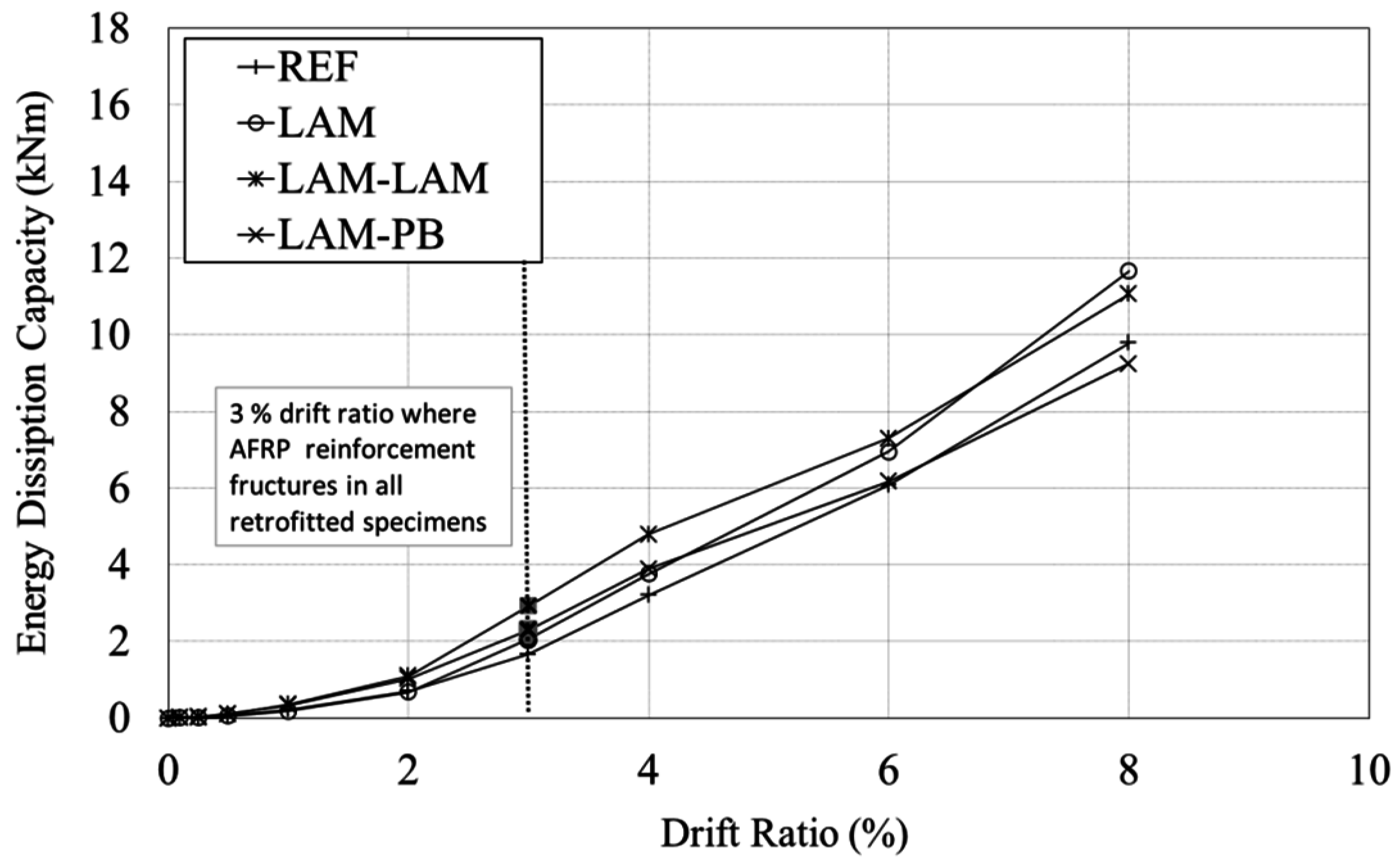
4.3. Energy Dissipation Capacities

5. Conclusions
- The reference column reached its theoretical flexural capacity, and exhibited a ductile behavior as foreseen during design.
- The retrofitted columns (LAM, LAM-LAM, LAM-PB) failed due to the rupture of AFRP reinforcement at around 3% drift ratio. At this drift ratio, the enhancement in strength was around 38%, 90% and 41% for the columns LAM, LAM-LAM, and LAM-PB, respectively, with respect to the reference column. It should be noted that drift ratios exceeding 3% may only be expected if substandard RC structures are subjected to severe earthquakes. Nevertheless, after AFRP reinforcements were fractured at around 3% drift ratio, the columns still resisted considerable lateral forces due to contribution of steel reinforcing bars until extremely large drift ratios (~6% to 8%). The column LAM-LAM exhibited a remarkably superior performance with respect to the reference and the other retrofitted columns due to additional AFRP anchorage reinforcement. When compared with the column LAM, the proposed anchorage type used for the column LAM-PB, limited the residual plastic deformations, while did not affect the lateral load capacity adversely. Therefore, this type of anchorage system can be utilized to limit the residual displacement and corresponding damage. It was observed that the predicted results through theoretical calculations satisfactorily captured the tested results by means of lateral load and deformation capacities, particularly, when 43% of the design rupture strain of FRP reinforcement was considered as the rupture strain of the FRP reinforcement during theoretical calculations.
- The AFRP reinforcement of the retrofitted columns ruptured at the interface of the column and the footing. The experimentally measured rupture strain of AFRP reinforcement was observed to be approximately 43% of design rupture strain of FRP reinforcement. Therefore, the strain reduction factor (70%) recommended by ACI 440-2R-08 [5] for NSM applications under monotonic loading conditions may lead to unconservative predictions of lateral load-deformation capacity for the proposed retrofitting technique in this study under cyclic loading conditions. Clearly, further investigations are also needed to accurately identify the theoretical seismic behavior of the columns retrofitted using NSM techniques under cyclic loading conditions.
Acknowledgments
Author Contributions
Conflicts of Interest
Notations
| AFRP | Aramid fiber reinforced polymer |
| Afrp | Cross-section area of the FRP anchor reinforcement |
| Afv | Area of FRP shear reinforcement |
| Ag | Gross area of the column section |
| Au | Cross-sectional area of the transverse reinforcing bar |
| bw | Web width of the column |
| CE | Environmental reduction factor according to ACI 440-2R-08 2008 |
| CFRP | Carbon fiber reinforced polymer |
| d | Distance from extreme compression fiber through centroid of tension steel reinforcement |
| dfv | Effective depth of FRP shear reinforcement |
| Ef | Tensile elastic modulus of FRP reinforcement |
| f'c | Design compressive strength of concrete |
| fmax | Tensile strength of longitudinal and transverse reinforcing bar |
| fy | Yield stress of longitudinal reinforcing bar |
| fyt | Design yield strength of transverse reinforcement |
| Fbond | Bond capacity of epoxy grout on AFRP reinforcement |
| Ffrp | Tensile strength of FRP |
| FRP | Fiber reinforced polymer |
| GFRP | Glass fiber reinforced polymer |
| H | Distance between the interface of the column and the footing and the point of application of the lateral load |
| hi | Distance between the center of the respective part and the tip of the column, where the lateral load is applied |
| ldb | Embedment length |
| li | Length of the respective part of the column |
| lp | plastic hinge length |
| M | Experimental moment capacity |
| M0 | Theoretical moment capacity calculated by fiber analysis approach |
| n | Number of plies of FRP sheet |
| NSM | Near surface mounted |
| Nu | Factored axial load normal to cross-section (to be taken as positive for compression) |
| RC | Reinforced Concrete |
| s | Spacing of shear reinforcement measured in a direction parallel to the longitudinal reinforcement |
| sf | Spacing of FRP reinforcement plies |
| tf | Nominal thickness of one ply of FRP reinforcement |
| u | Perimeter of the FRP anchor |
| Vc | Nominal shear strength provided by concrete |
| Vs | Nominal shear strength provided by shear reinforcement |
| Vn | Nominal shear strength |
| Vr-frp | Nominal shear strength (with the contribution of FRP) |
| Vf | FRP contribution to shear strength |
| wf | Effective width of FRP reinforcement |
| δt | Top displacement of the column |
| θp | Plastic rotation |
| ɛc0 | Axial strain corresponding to unconfined concrete strength |
| ɛcc | Axial strain corresponding to confined concrete strength |
| ɛfe | Effective strain of FRP sheet attained at failure |
| εfu | Design rupture strain of FRP reinforcement |
| εfu* | Ultimate rupture strain of FRP reinforcement declared by manufacturer |
| ρs | Existing volumetric ratio of transverse reinforcement of columns |
| ρsm | Required volumetric ratio of transverse reinforcement of columns |
| τb | Uniform bond strength along the anchorage length |
| χi | Curvature of the respective part of the column |
| χp | Curvature of the plastic part of the column |
| ψf | FRP strength reduction factor |
References
- CEB-FIB. Externally Bonded FRP Reinforcement for RC Structures; Technical report for International Federation for Structural Concrete: Lausanne, Switzerland, 2001. [Google Scholar]
- Pessiki, S.; Harries, K.A.; Kestner, J.T.; Sause, R.; Ricles, J.M. Axial behavior of reinforced concrete columns confined with FRP jackets. J. Compos. Constr. 2001, 5, 237–245. [Google Scholar] [CrossRef]
- Bakis, C.E.; Bank, L.C.; Brown, V.L.; Cosenza, E.; Davalos, J.F.; Lesko, J.J.; Machida, A.; Rizkalla, S.H.; Triantafillou, T.C. Fiber-reinforced polymer composites for construction-State-of-the-Art Review. J. Compos. Constr. 2002, 6, 73–87. [Google Scholar] [CrossRef]
- Lam, L.; Teng, J.G. Design-oriented stress-strain model for FRP-confined concrete. Constr. Build. Mater. 2003, 17, 471–489. [Google Scholar] [CrossRef]
- ACI 440.2R-08. Guide for design and construction of externally bonded FRP systems for strengthening concrete structures. American Concrete Institute 440: Farmington Hills, MI, USA, 2008.
- Bank, L.C. Progressive failure and ductility of FRP composites for construction: Review. J. Compos. Constr. 2013, 17, 406–419. [Google Scholar] [CrossRef]
- Bennitz, A.; Schmidth, J.W.; Nilimaa, J.; Taljsten, B.; Goltermann, P.; Ravn, D.L. Reinforced concrete T-beams externally prestressed with unbonded carbon fiber-reinforced polymer tendons. Struct. J. 2012, 109, 521–530. [Google Scholar]
- Lou, T.; Lopes, S.M.R.; Lopes, A. Numerical analysis of behaviour of concrete beams with external FRP tendons. Constr. Build. Mater. 2012, 35, 970–978. [Google Scholar] [CrossRef]
- Lou, T.; Lopes, S.M.R.; Lopes, A. External CFRP tendon members: Secondary reactions and moment redistribution. Compos. Eng. 2014, 57, 250–261. [Google Scholar] [CrossRef]
- Seible, F.; Priestley, M.J.; Hegemier, G.A.; Innamorato, D. Seismic retrofit of RC columns with continuous carbon fiber jackets. J. Compos. Constr. 1997, 1, 52–62. [Google Scholar] [CrossRef]
- Sheikh, S.; Yau, G. Seismic behavior of concrete columns confined with steel and fiber-reinforced polymers. Struct. J. 2002, 99, 72–80. [Google Scholar]
- Antonopoulos, C.P.; Triantafillou, T.C. Experimental investigation of FRP-strengthened RC beam-column joints. J. Compos. Constr. 2003, 7, 39–49. [Google Scholar] [CrossRef]
- Iacobucci, R.D.; Sheikh, A.S.; Bayrak, O. Retrofit of square concrete columns with carbon fiber-reinforced polymer for seismic resistance. Struct. J. 2003, 100, 785–794. [Google Scholar]
- Xiao, Y. Applications of FRP composites in concrete columns. Adv. Struct. Eng. 2004, 7, 335–343. [Google Scholar] [CrossRef]
- Prota, A.; Nanni, A.; Manfredi, G.; Cosenza, E. Selective upgrade of underdesigned reinforced concrete beam-column joints using carbon fiber polymers. Struct. J. 2004, 101, 699–707. [Google Scholar]
- Bousias, S.N.; Triantafillou, T.C.; Fardis, M.N.; Spathis, L.; O’Regan, B.A. Fiber-reinforced polymer retrofitting of rectangular reinforced concrete columns with or without corrosion. Struct. J. 2004, 101, 512–520. [Google Scholar]
- Chang, S.; Li, Y.; Loh, C. Experimental study of seismic behaviors of as-built and carbon fiber reinforced plastics repaired reinforced concrete bridge columns. J. Bridge Eng. 2004, 9, 391–402. [Google Scholar] [CrossRef]
- Memon, M.S.; Sheikh, S.A. Seismic resistance of square concrete columns retrofitted with glass fiber-reinforced polymer. Struct. J. 2005, 102, 774–783. [Google Scholar]
- Tsonos, A.G. Effectiveness of CFRP-jackets in post-earthquake and pre-earthquake retrofitting of beam-column subassemblages. Struct. Eng. Mech. 2007, 27, 393–408. [Google Scholar] [CrossRef]
- Ilki, A.; Demir, C.; Bedirhanoglu, I.; Kumbasar, N. Seismic retrofit of brittle and low-strength RC columns using fiber reinforced polymer and cementitious composites. Adv. Struct. Eng. 2009, 12, 325–347. [Google Scholar] [CrossRef]
- Garcia, R.; Hajirasouliha, I.; Pilakoutas, K. Seismic behaviour of deficient RC frames strengthened with CFRP composites. Eng. Struct. 2010, 32, 3075–3085. [Google Scholar] [CrossRef]
- Ilki, A.; Bedirhanoglu, I.; Kumbasar, N. Behavior of FRP retrofitted joints built with plain bars and low-strength concrete. J. Compos. Constr. 2011, 15, 312–326. [Google Scholar] [CrossRef]
- Wang, Z.; Wang, D.; Smith, S.T.; Lu, D. CFRP-confined square RC columns. I: Experimental investigation. J. Compos. Constr. 2011, 16, 150–160. [Google Scholar] [CrossRef]
- Jirawattanasomkul, T.; Zhang, D.W.; Ueda, T. Prediction of the post-peak behavior of reinforced concrete columns with and without FRP-jacketing. Eng. Struct. 2013, 56, 1511–1526. [Google Scholar] [CrossRef]
- Parvin, A.; Brighton, D. FRP composites strengthening of concrete columns under various loading conditions. Polymers 2014, 6, 1040–1056. [Google Scholar] [CrossRef]
- Demir, C.; Darılmaz, K.; Ilki, A. Cyclic stress–strain relationships of FRP confined concrete members. Arabian J. Sci. Eng. 2015, 40, 363–379. [Google Scholar] [CrossRef]
- Nanni, A.; Alkhrdaji, T.; Chen, G.; Barker, M.; Yang, X.; Mayo, R. Overview of testing to failure program of a highway bridge strengthened with FRP composites. In Proceedings of Fourth International Symposium on FRP for Reinforcement of Concrete Structures, Baltimore, MD, USA, November 1999; pp. 69–80.
- De Lorenzis, L.; Nanni, A. Bond between near surface mounted fiber reinforced polymer rods and concrete in structural strengthening. Struct. J. 2002, 99, 123–132. [Google Scholar]
- De Lorenzis, L.; Lundgren, K.; Rizzo, A. Anchorage length of near-surface mounted fiber reinforced polymer bars for concrete strengthening-experimental investigation and numerical modelling. Struct. J. 2004, 101, 269–278. [Google Scholar]
- Hassan, T.K.; Rizkalla, S.H. Bond mechanism of near-surface-mounted fiber-reinforced polymer bars for flexural strengthening of concrete structures. Struct. J. 2004, 101, 830–839. [Google Scholar]
- El-Hacha, R.; Rizkalla, S.H. Near-surface-mounted fiber-reinforced polymer reinforcements for flexural strengthening of concrete structures. Struct. J. 2004, 101, 717–726. [Google Scholar]
- Barros, J.A.O.; Dias, S.J.E. Near surface mounted CFRP laminates for shear strengthening of concrete beams. Cem. Concr. Compos. 2006, 28, 276–292. [Google Scholar] [CrossRef]
- Nordin, H.; Täljsten, B. Concrete beams strengthened with prestressed near surface mounted CFRP. J. Compos. Constr. 2006, 10, 60–68. [Google Scholar] [CrossRef]
- Liu, I.S.T.; Oehlers, D.J.; Seracino, R. Tests on the ductility of reinforced concrete beams retrofitted with FRP and steel near-surface mounted plates. J. Compos. Constr. 2006, 10, 106–114. [Google Scholar] [CrossRef]
- Teng, J.G.; de Lorenzis, L.; Wang, B.; Li, R.; Wong, T.N.; Lam, L. Debonding failures of RC beams strengthened with near surface mounted CFRP strips. J. Compos. Constr. 2006, 10, 92–105. [Google Scholar] [CrossRef]
- De Lorenzis, L.; Teng, J.G. Near-surface mounted FRP reinforcement: An emerging technique for strengthening structures. Compos. Eng. 2007, 38, 119–143. [Google Scholar] [CrossRef]
- Seracino, R.; Raizal Saifulnaz, M.R.; Oehlers, D.J. Generic debonding resistance of EB and NSM plate-to-concrete joints. J. Compos. Constr. 2007, 11, 62–70. [Google Scholar] [CrossRef]
- Castro, E.K.; Melo, G.S.; Nagato, Y. Flexural strengthening of RC “t” beams with near surface mounted (NSM) FRP reinforcements. In Proceedings of International Symposium on FRP Reinforcement of Concrete Structures (FRPRCS-8), Patras, Greece, 16–18 July 2007.
- Chikh, N.; Foret, G.; Bousalem, B.; Firas, S. Analysis of reinforced concrete members strengthened with near-surface-mounted CFRP. In Proceedings of 11DBMC Conference on Durability of Building Materials and Components, Istanbul, Turkey, 11–14 May 2008.
- El-Maaddawy, T.A.; El-Dieb, A.S. Near-surface-mounted composite system for repair and strengthening of reinforced concrete columns subjected to axial load and biaxial bending. J. Compos. Constr. 2011, 15, 602–614. [Google Scholar] [CrossRef]
- Sharaky, I.A.; Torres, L.; Comas, J.; Barris, C. Flexural response of reinforced concrete (RC) beams strengthened with near surface mounted (NSM) fibre reinforced polymer (FRP) bars. Compos. Struct. 2013, 109, 8–22. [Google Scholar] [CrossRef]
- Bilotta, A.; Ceroni, F.; Barros, J.; Costa, I.; Palmieri, A.; Szabó, Z.; Nigro, E.; Matthys, S.; Balazs, G.; Pecce, M. Bond of NSM FRP-strengthened concrete: Round robin test initiative. J. Compos. Constr. 2015. [Google Scholar] [CrossRef]
- Sena Cruz, J.M.; Barros, J.A.O.; Gettu, R.; Azevedo, A.F.M. Bond behavior of near surface mounted CFRP laminate strips under monotonic and cyclic loading. J. Compos. Constr. 2006, 10, 295–303. [Google Scholar] [CrossRef]
- Badawi, M.; Soudki, K. Fatigue behavior of RC beams strengthened with NSM CFRP rods. J. Compos. Constr. 2009, 13, 415–421. [Google Scholar] [CrossRef]
- Ceroni, F. Experimental performances of RC beams strengthened with FRP materials. Constr. Build. Mater. 2010, 24, 1547–1559. [Google Scholar] [CrossRef]
- Ilki, A.; Kumbasar, N. The behavior of damaged reinforced concrete members strengthened by carbon fiber reinforced polymer composites. Tech. J. Turk. Chamb. Civil Eng. 2002, 13, 2597–2616, (In Turkish with English abstract). [Google Scholar]
- Bournas, D.A.; Triantafillou, T.C. Flexural strengthening of reinforced concrete columns with near surface mounted FRP or stainless steel. Struct. J. 2009, 106, 495–505. [Google Scholar]
- Goksu, C.; Polat, A.; Ilki, A. Attempt for seismic retrofit of existing sub-standard RC members under reversed cyclic flexural effects. J. Compos. Constr. 2012, 16, 286–299. [Google Scholar] [CrossRef]
- Fahmy, M.F.M.; Wu, Z. Retrofitting of existing RC square bridge columns using basalt FRP rebars. Available online: http://www.iifc-hq.org/proceedings/CICE_2012/02_FRP%20in%20Seismic%20Retrofitting/02_495_Fahmy,Wu_RETROFITTING%20OF%20EXISTING%20RC%20SQUARE.pdf (accessed on 27 November 2015).
- Vrettos, I.; Kefela, E.; Triantafillou, T.C. Innovative flexural strengthening of reinforced concrete columns using carbon-fiber anchors. Struct. J. 2013, 110, 63–70. [Google Scholar]
- Li, X.; Lv, H.L.; Zhang, G.C.; Sha, S.Y.; Zhou, S.C. Seismic retrofitting of rectangular reinforced concrete columns using fiber composites for enhanced flexural strength. J. Reinf. Plast. Compos. 2013, 32, 619–630. [Google Scholar] [CrossRef]
- Goksu, C.; Uzunhasanoglu, A.; Seyhan, E.C.; Ilki, A. Seismic retrofit of sub-standard RC columns with embedded aramid FRP reinforcement. In Proceedings of SMAR 2013 Second Conference on Smart Monitoring, Assessment and Rehabilitation of Civil Structures, Istanbul, Turkey, 9–11 September 2013.
- Faustino, P.; Chastre, C. Flexural strengthening of columns with CFRP composites and stainless steel: Cyclic behavior. J. Struct. Eng. 2015. [Google Scholar] [CrossRef]
- CNR-DT 200/2004. Guide for the design and construction of externally bonded FRP systems for strengthening existing structures. Available online: http://www.cnr.it/documenti/norme/IstruzioniCNR_DT200_2004_eng.pdf (accessed on 27 November 2015).
- Akkaya, Y.; Demir, N. Durability issues in existing buildings and new infrastructure projects. In Proceedings of Joint Symposium on Concrete Engineering (JSCE), Istanbul, Turkey, 9 June 2010.
- Eurocode 8-Part 3. Assessment and retrofitting of buildings. European Committee for Standardization: Brussels, Belgium, 2005.
- TSDC. Regulations for buildings to be constructed in earthquake prone areas. Turkish Seismic Design Code: Ankara, Turkey, 2007. [Google Scholar]
- Eurocode 2: Design of concrete structures. Part 1. General rules and rules for buildings. European Committee for Standardization: Brussels, Belgium, 2004.
- TS EN 12390–3. Testing hardened concrete-Part 3: Compressive strength of test specimens. Turkish Standards Institute: Ankara, Turkey, 2003.
- TS 708. Steel bars for concrete. Turkish Standards Institute: Ankara, Turkey, 1996.
- Part 3: Structural and non-structural repair. In Products and Systems for the Protection and Repair of Concrete Structures. Definitions, Requirements, Quality Control and Evaluation of Conformity; BS EN 1504–3:2005; British Standard Institute: London, UK, 2006.
- Part 4: Structural bonding. In Products and Systems for the Protection and Repair of Concrete Structures. Definitions, Requirements, Quality Control and Evaluation of Conformity; EN 1504–4:2004; British Standard Institute: London, UK, 2004.
- TS-EN 196–1. Methods of testing cement-Part 1: Determination of strength. Turkish Standards Institute: Ankara, Turkey, 2009.
- ASTM D3039. Standard test method tensile properties of polymer matrix composite materials. ASTM International: West Conshohocken, PA, USA, 2014.
- Matamoros, A.B.; Sozen, M.A. Drift limits of high-strength concrete columns subjected to load reversals. J. Struct. Eng. 2003, 129, 297–313. [Google Scholar] [CrossRef]
- Bournas, D.A.; Triantafillou, T.C. Bond strength of lap spliced bars in concrete confined with composite jackets. J. Compos. Constr. 2011, 15, 156–167. [Google Scholar] [CrossRef]
- XTRACT 3.0.8. Cross-sectional structural analysis of components. TRC: Rancho Cordova, CA, USA, 2007.
- Ilki, A.; Peker, O.; Karamuk, E.; Demir, C.; Kumbasar, N. FRP retrofit of low and medium strength circular and rectangular reinforced concrete columns. J. Mater. Civil Eng. 2008, 20, 169–188. [Google Scholar] [CrossRef]
- ACI-318M-14. Metric building code requirements for structural concrete and commentary. American Concrete Institute 318: Farmington Hills, MI, USA, 2014.
- ACI-355–1R-91. State-of-the-art report on anchorage to concrete. American Concrete Institute 355: Farmington Hills, MI, USA, 1991.
© 2015 by the authors; licensee MDPI, Basel, Switzerland. This article is an open access article distributed under the terms and conditions of the Creative Commons by Attribution (CC-BY) license (http://creativecommons.org/licenses/by/4.0/).
Share and Cite
Seyhan, E.C.; Goksu, C.; Uzunhasanoglu, A.; Ilki, A. Seismic Behavior of Substandard RC Columns Retrofitted with Embedded Aramid Fiber Reinforced Polymer (AFRP) Reinforcement. Polymers 2015, 7, 2535-2557. https://doi.org/10.3390/polym7121527
Seyhan EC, Goksu C, Uzunhasanoglu A, Ilki A. Seismic Behavior of Substandard RC Columns Retrofitted with Embedded Aramid Fiber Reinforced Polymer (AFRP) Reinforcement. Polymers. 2015; 7(12):2535-2557. https://doi.org/10.3390/polym7121527
Chicago/Turabian StyleSeyhan, Engin C., Caglar Goksu, Ahmet Uzunhasanoglu, and Alper Ilki. 2015. "Seismic Behavior of Substandard RC Columns Retrofitted with Embedded Aramid Fiber Reinforced Polymer (AFRP) Reinforcement" Polymers 7, no. 12: 2535-2557. https://doi.org/10.3390/polym7121527
APA StyleSeyhan, E. C., Goksu, C., Uzunhasanoglu, A., & Ilki, A. (2015). Seismic Behavior of Substandard RC Columns Retrofitted with Embedded Aramid Fiber Reinforced Polymer (AFRP) Reinforcement. Polymers, 7(12), 2535-2557. https://doi.org/10.3390/polym7121527