
New Proposal for Flexural Strengthening of Reinforced Concrete Beams Using CFRP T-Shaped Profiles


Abstract
: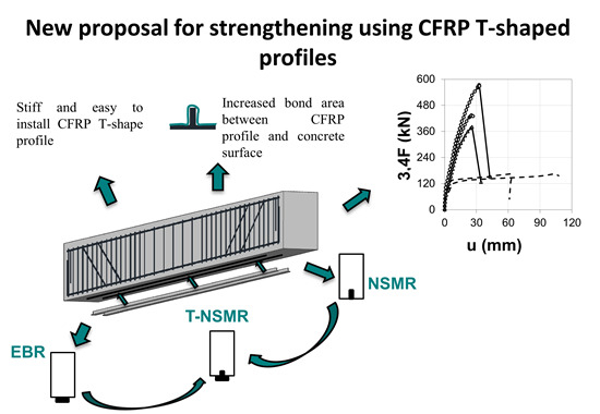
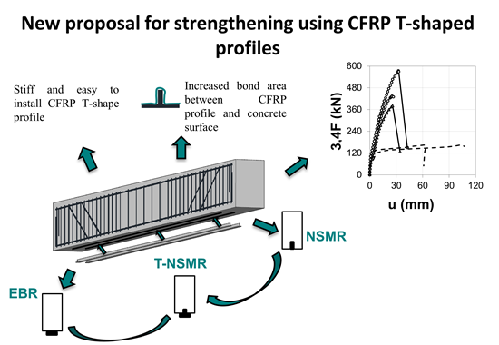
1. Introduction
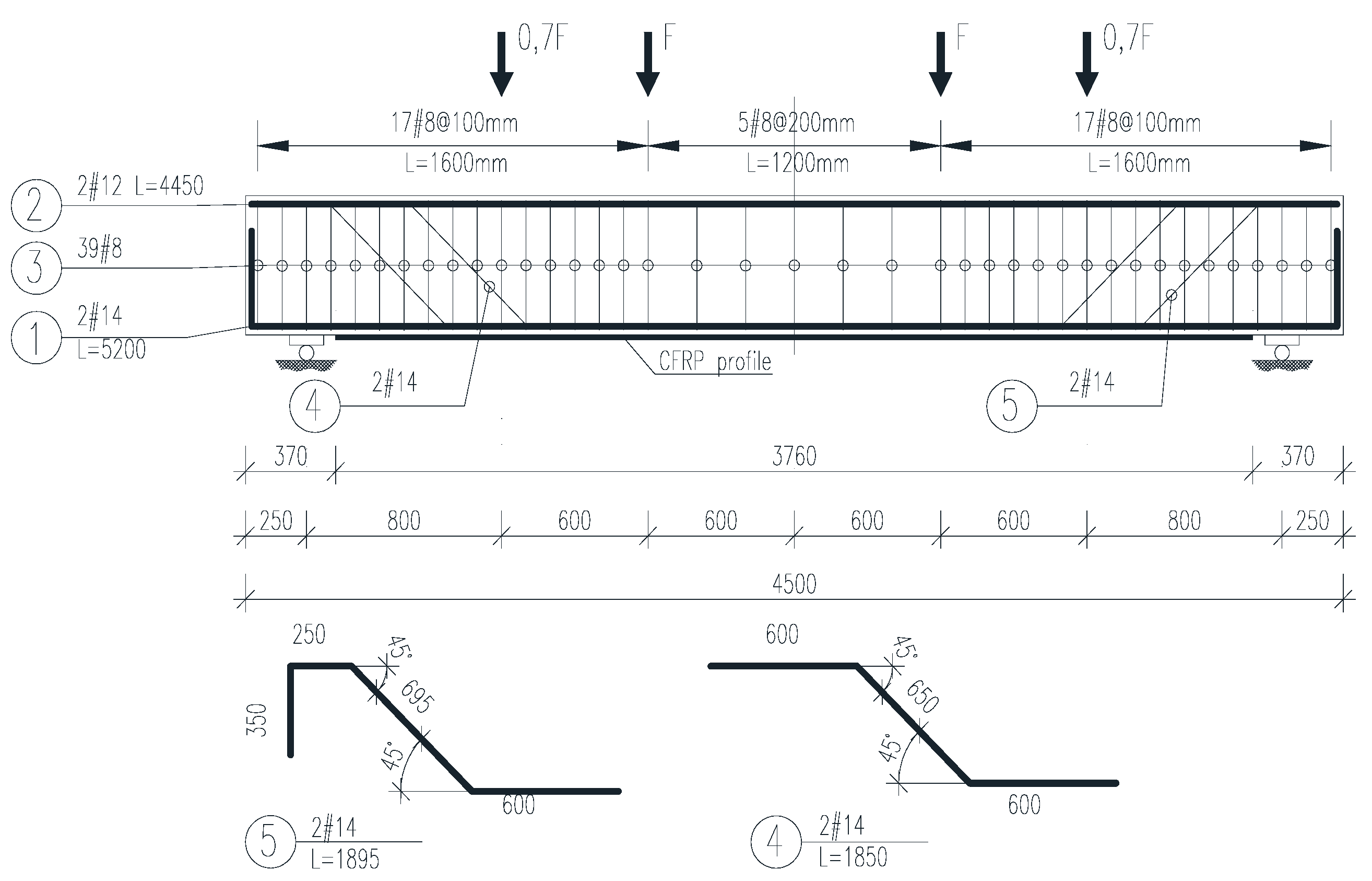
2. Experimental Program

| Series | NO. | Symbol | Tensile reinforcement | Designed compressive cubic concrete strength, fc,cube | CFRP profile |
|---|---|---|---|---|---|
| (mm) | (MPa) | (-) | |||
| C30/37 | 1 | B30-214-A | 2 × 14 | 30 | - |
| 2 | B30-214-1T-15 | 1 × T15 | |||
| 3 | B30-214-2T-15 | 2 × T15 | |||
| 4 | B30-214-1T-30 | 1 × T30 | |||
| C50/60 | 5 | B60-214-A | 2 × 14 | 60 | - |
| 6 | B60-214-1T-15 | 1 × T15 | |||
| 7 | B60-214-2T-15 | 2 × T15 | |||
| 8 | B60-214-1T-30 | 1 × T30 | |||
| 9 | B60-214-2T-30 | 2 × T30 |
2.1. Material Properties
| Concrete class | No. | Symbol | Concrete strength | Elasticity modulus | ||
|---|---|---|---|---|---|---|
| Compressive | Tensile | |||||
| fccm,cube | fccm,cyl | fctm,cube | Ecm | |||
| (MPa) | (GPa) | |||||
| C30/37 | 1 | B30-214-A | 41.5 | 34.9 | 3.5 | 28.9 |
| 2 | B30-214-1T-15 | - | 36.5 | - | 26.1 | |
| 3 | B30-214-2T-15 | 41.4 | 34.8 | 3.5 | 28.7 | |
| 4 | B30-214-1T-30 | 42.8 | 36.0 | 3.7 | 28.9 | |
| C50/60 | 5 | B60-214-A | 58.0 | 50.0 | 4.0 | 34.1 |
| 6 | B60-214-1T-15 | 58.0 | 50.0 | 4.0 | 34.1 | |
| 7 | B60-214-2T-15 | 59.0 | 51.0 | 4.0 | 34.3 | |
| 8 | B60-214-1T-30 | 62.9 | 45.4 | 4.4 | 35.7 | |
| 9 | B60-214-2T-30 | 62.8 | 45.4 | 4.0 | 34.4 | |
| Steel bar | Yielding strength | Yielding strain | Tensile strength | Ultimate strain | Young modulus | |
|---|---|---|---|---|---|---|
| Upper fsy,u | Lower fsy,l | εsy | fsu | εsu | Es | |
| (mm) | (MPa) | (%) | (%) | (%) | (GPa) | |
| 8 | 558.9 | 548.9 | 2.5 | 622.4 | 14.2 | 219.5 |
| 12 | 589.2 | 576.7 | 2.8 | 668.5 | 9.3 | 207.7 |
| 14 | 550.1 | 523.3 | 2.5 | 634.5 | 15.4 | 209.0 |
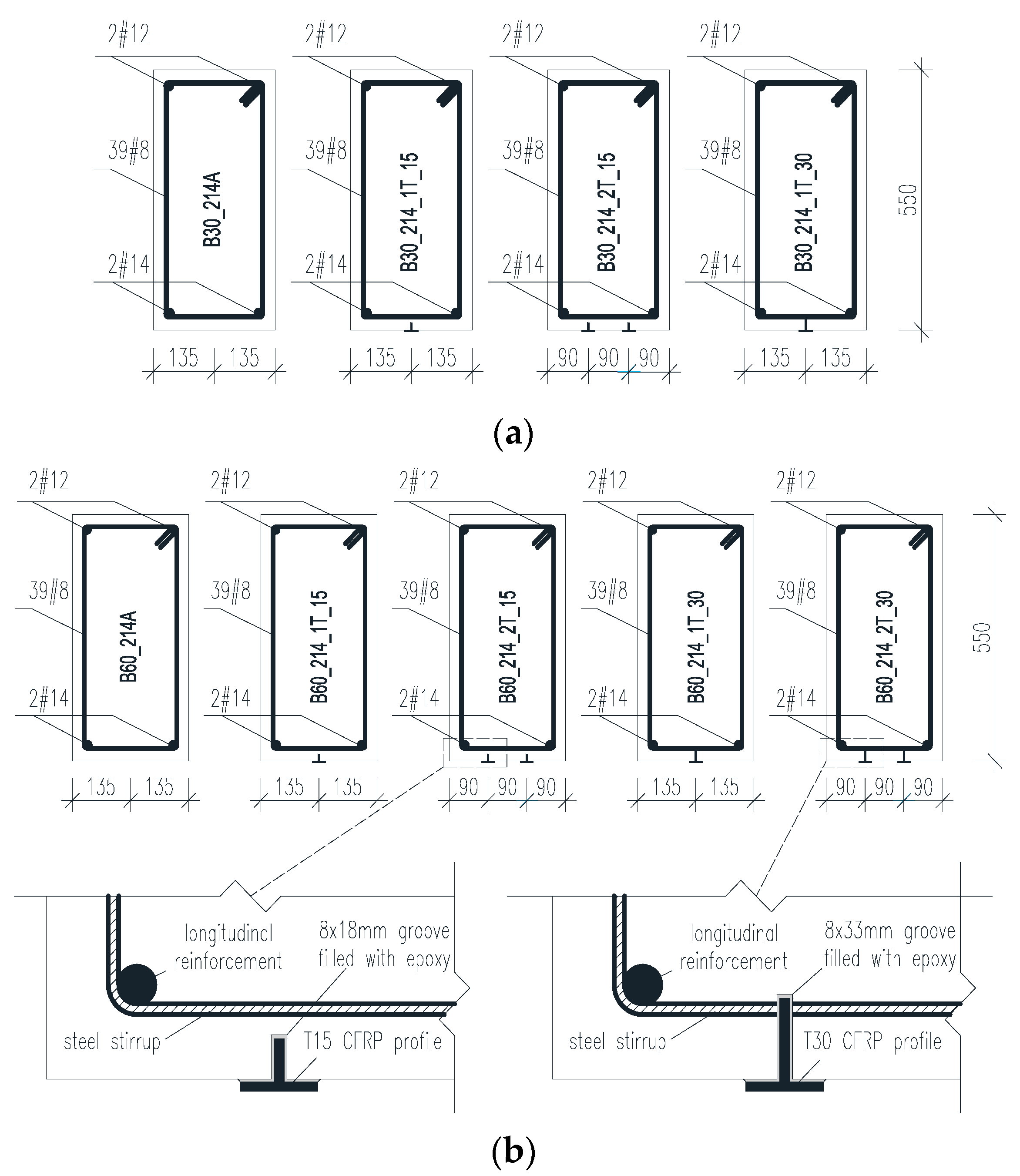
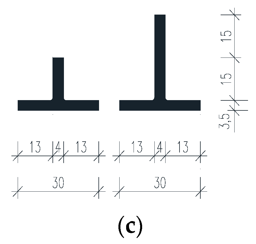
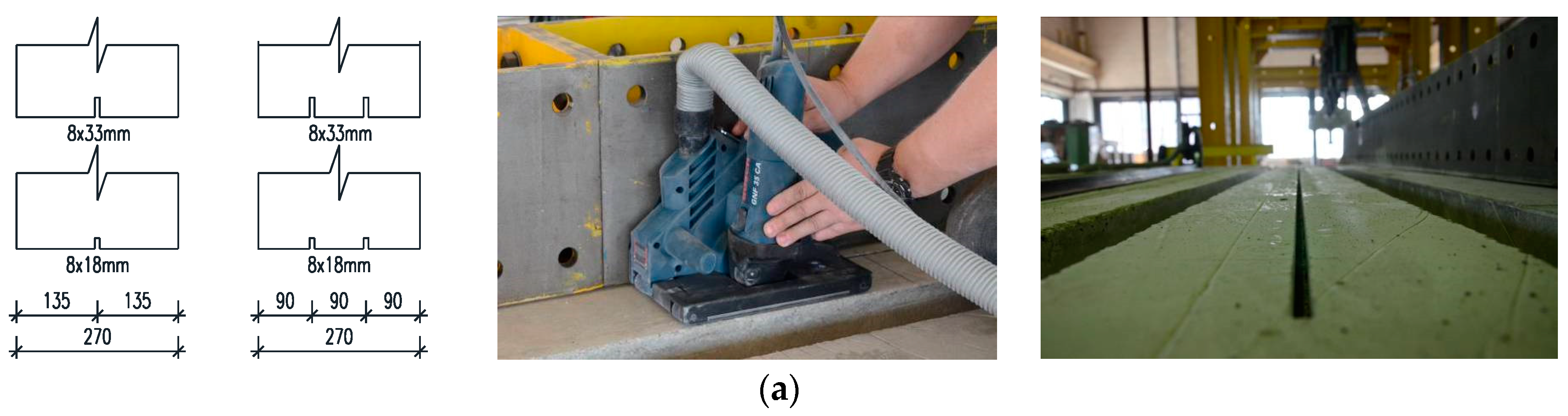
2.2. Strengthening Procedure
- Cleaning slots of laitance by compressed air;
- Surface preparation of the CFRP shapes by cleaning with the acetone;
- Preparation of the epoxy adhesive according to the manufacturer recommendations and filling the slots with the epoxy adhesive (Figure 3b);
- Application of the epoxy adhesive on the flange of the T shaped CFRP profile (Figure 3b);
- Introducing the profile’s web into the slots and bonding of the profile’s flange on the bottom surface of the beams;
- Removing the excess epoxy adhesive (Figure 3c);


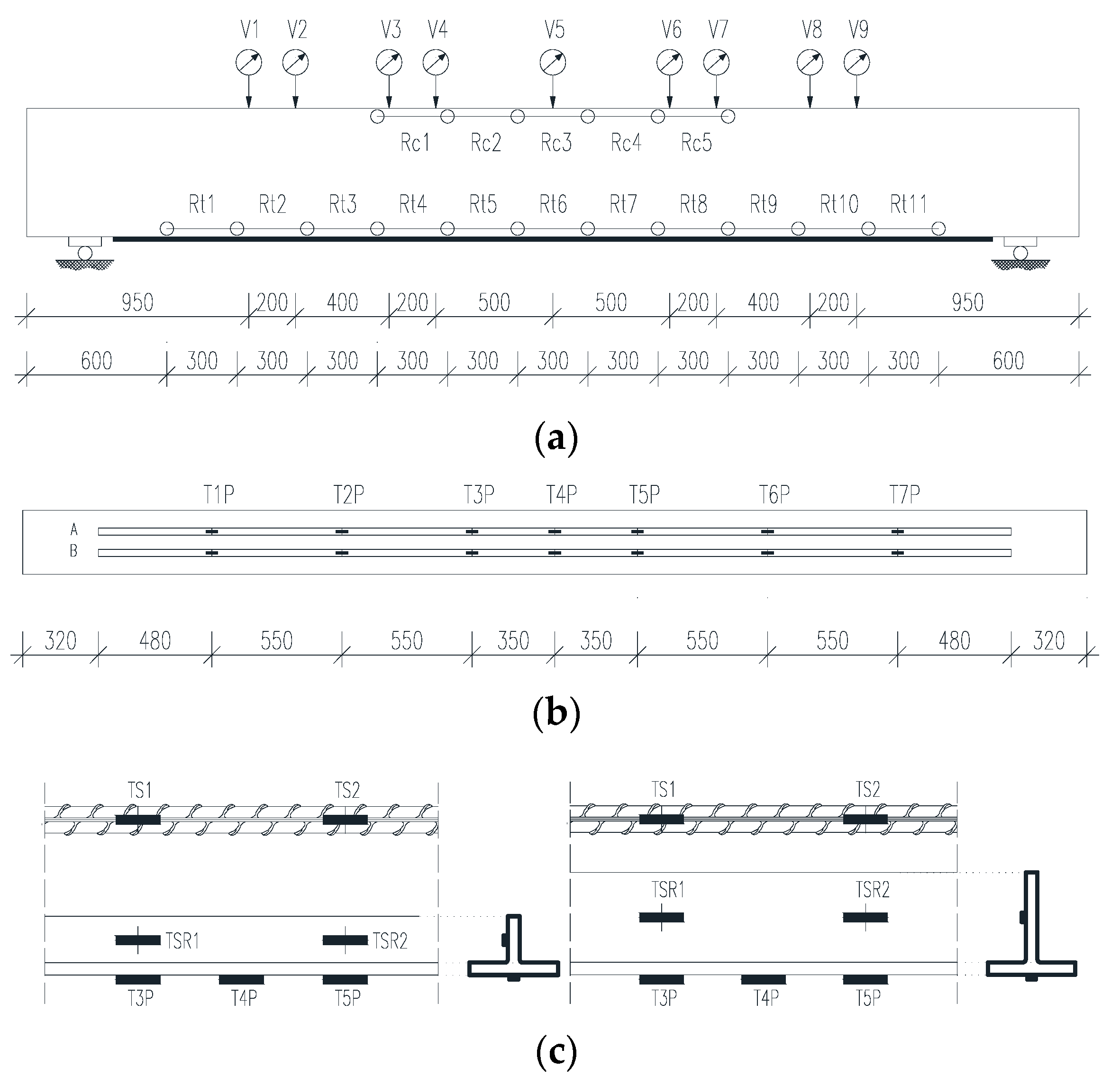
2.3. Test Configuration and Instrumentation

3. Results and Discussion
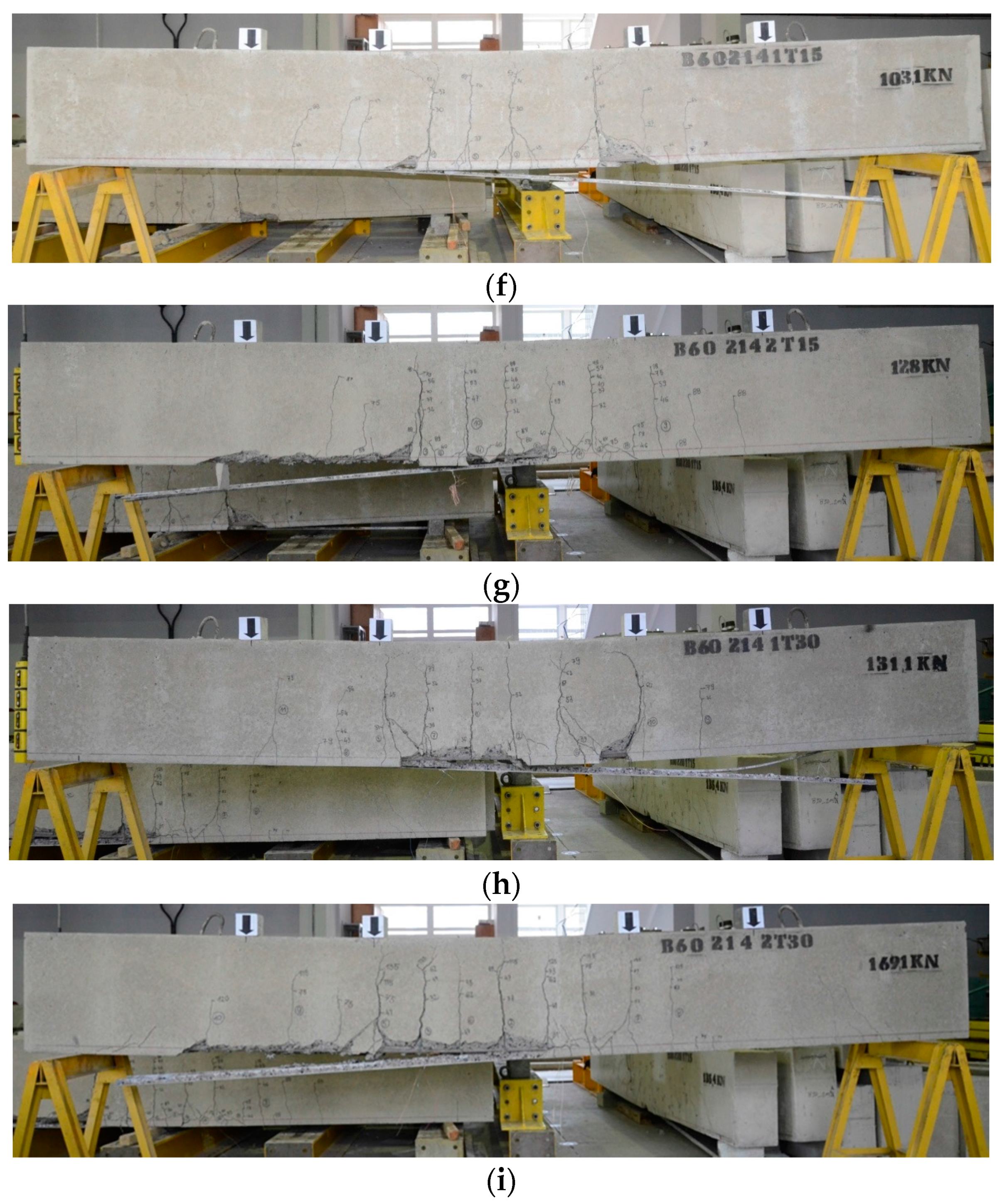
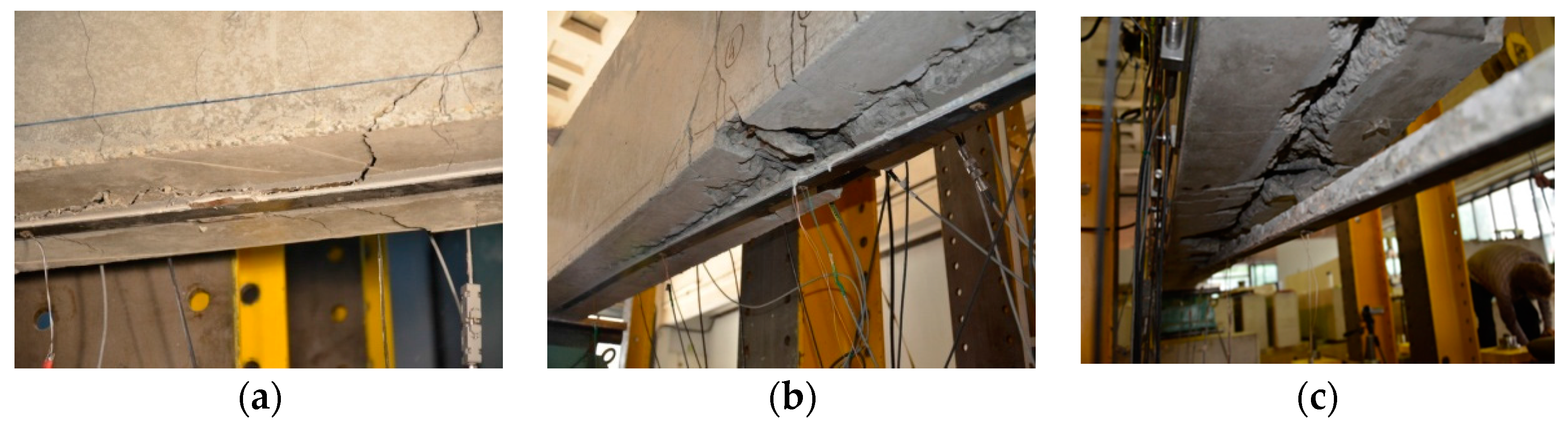
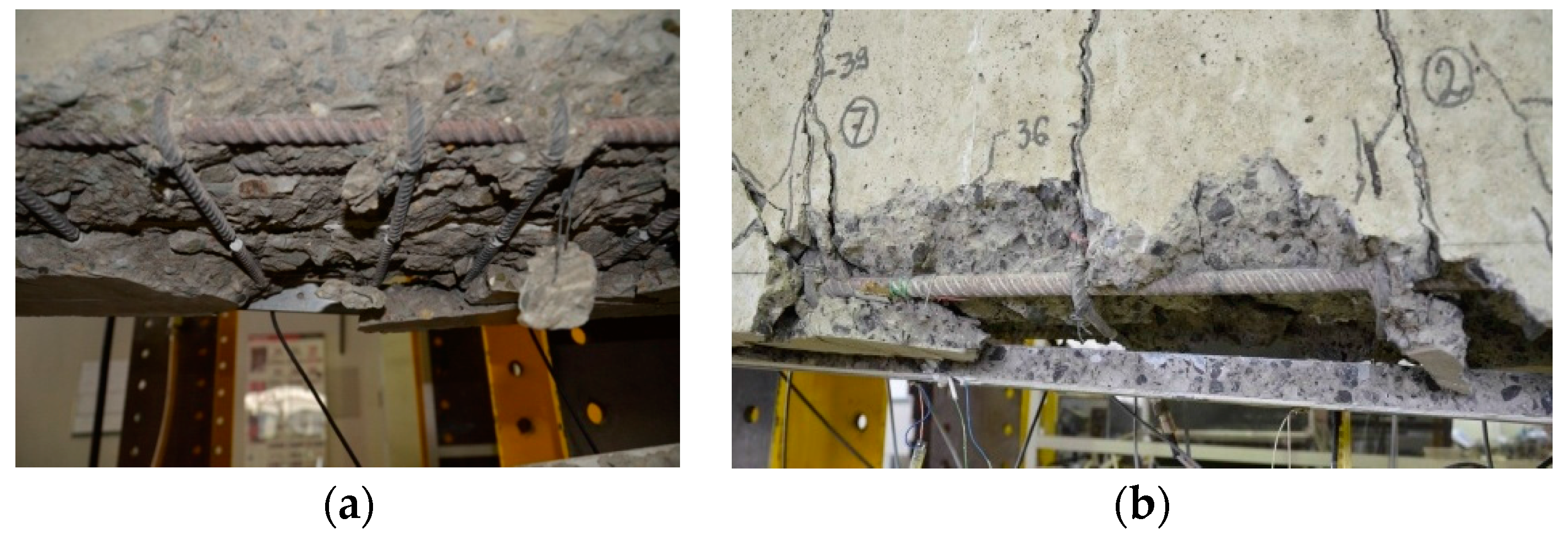
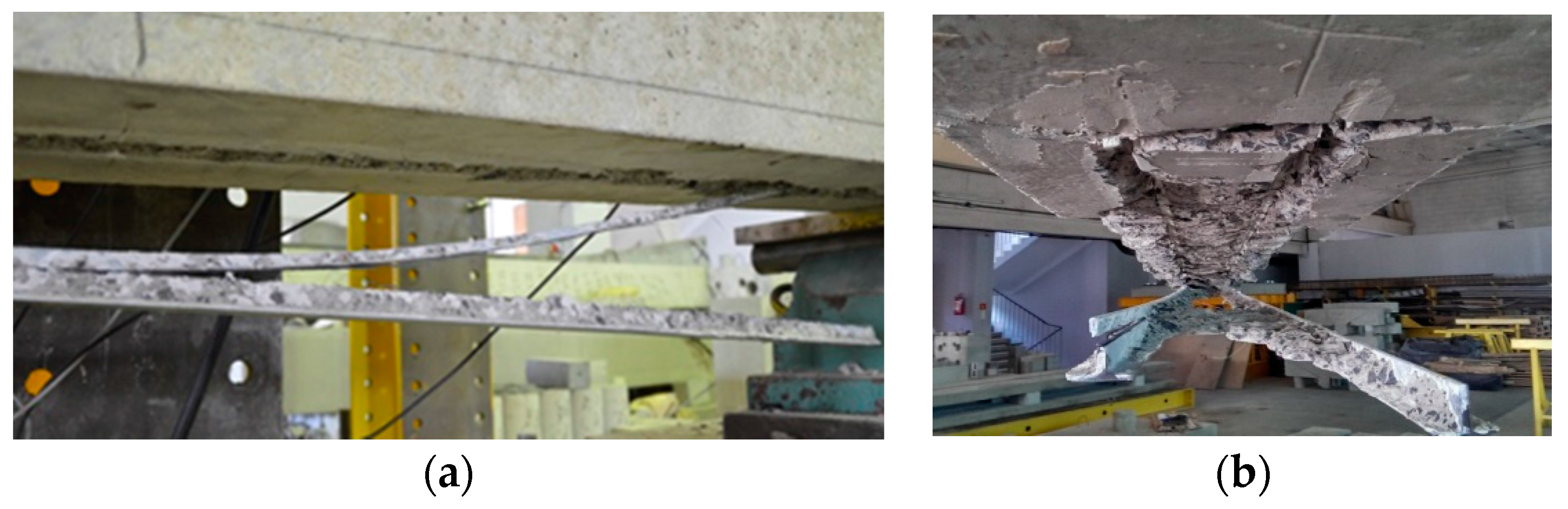
3.1. Failure Modes


| Series | Figure 5 | Symbol | Failure modes |
|---|---|---|---|
| C30/37 | a | B30-214-A | SY + CC |
| b | B30-214-1T-15 | ICD + CCS | |
| c | B30-214-2T-15 | ICD + CCS | |
| d | B30-214-1T-30 | ICD + CCS | |
| C50/60 | e | B60-214-A | SY + CC |
| f | B60-214-1T-15 | ICD + BPA | |
| g | B60-214-2T-15 | ICD + CCS | |
| h | B60-214-1T-30 | ICD + LFP | |
| i | B60-214-2T-30 | ICD + LFP |


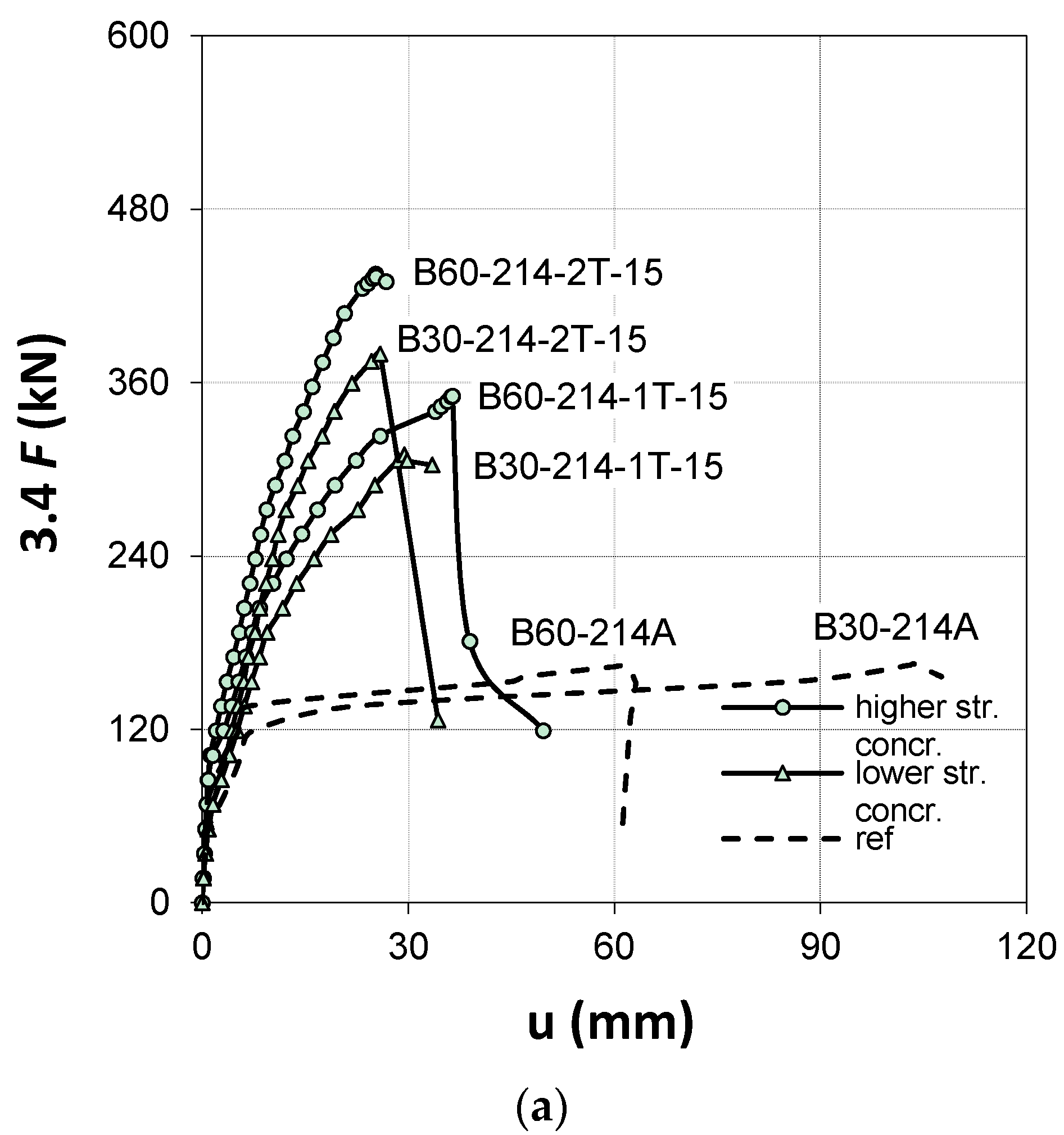
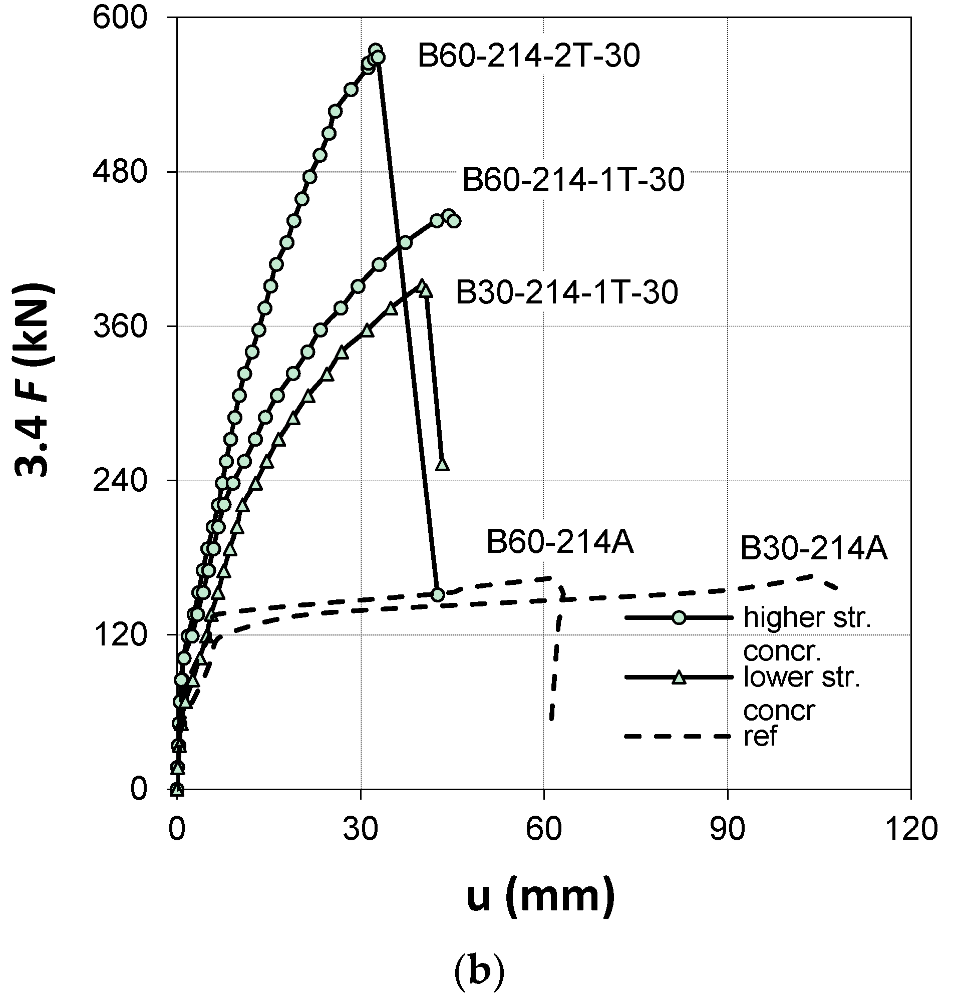
3.2. Beam Load Carrying Capacity
| 1 | 2 | 3 | 4 | 5 | 6 | 7 | 8 | 9 | 10 | 11 | 12 |
|---|---|---|---|---|---|---|---|---|---|---|---|
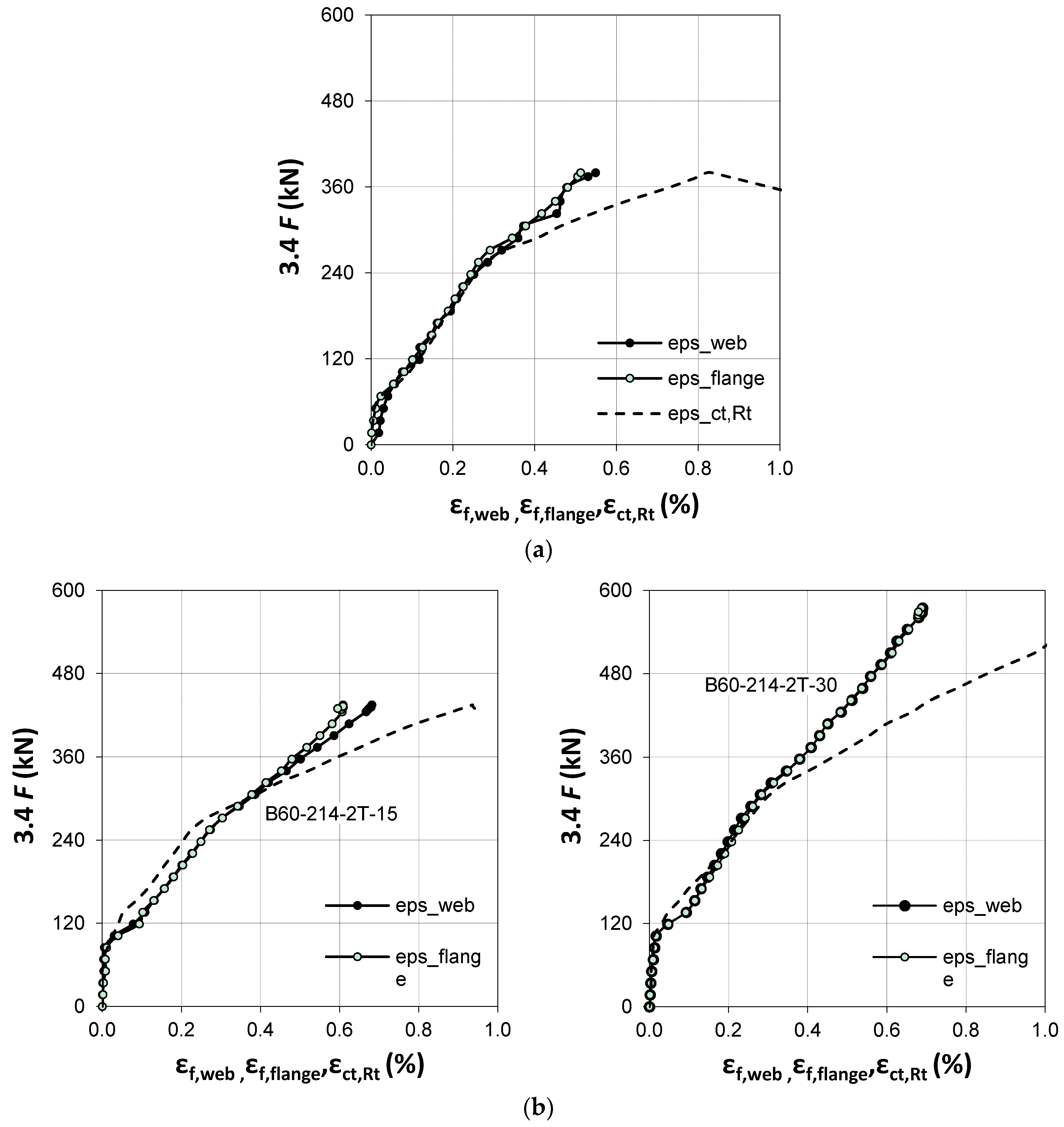
| No. | Symbol | 3.4 Fcr | Δcr | 3.4 Fy | Δy | 3.4 Fu | Δu | ηf | εf.flange | εf.web | ηε |
| (kN) | (mm) | (kN) | (mm) | (kN) | (mm) | (%) | (%) | (%) | (%) | ||
| 1 | B30-214-A | 61.2 | 1.8 | 119 | 6.8 | 166.6 | 103.5 | - | - | - | - |
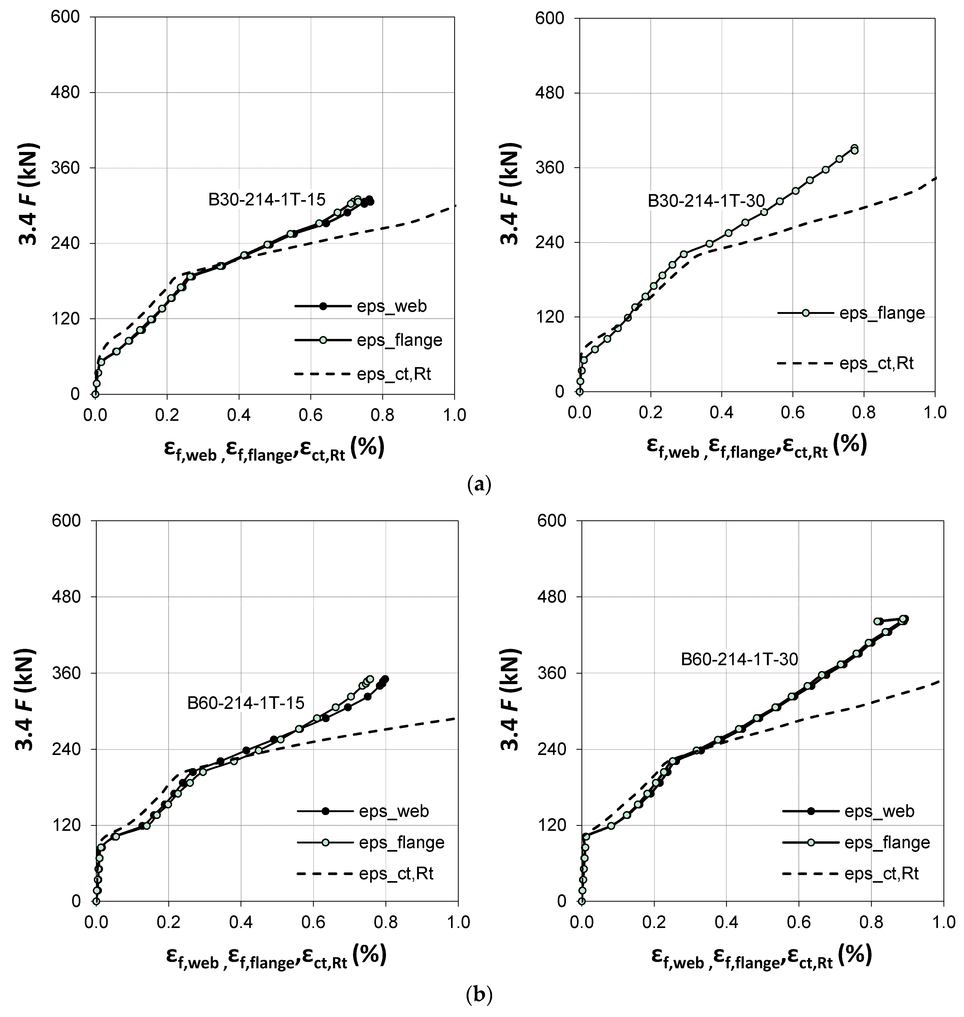
| 2 | B30-214-1T-15 | 81.6 | 2.5 | 186.6 | 9.4 | 309.4 | 29.4 | 85.7 | 0.73 | 0.75 | 69.0 |
| 3 | B30-214-2T-15 | 61.2 | 1.2 | 255 | 6.8 | 380.8 | 25.9 | 128.6 | 0.52 | 0.55 | 48.0 |
| 4 | B30-214-1T-30 | 68.0 | 1.4 | 221.3 | 10.8 | 391.0 | 40.1 | 134.7 | 0.77 | X | 71.0 |
| 5 | B60-214-A | 78.2 | 0.7 | 136 | 6.6 | 163.2 | 61.7 | - | - | - | - |
| 6 | B60-214-1T-15 | 102 | 1.5 | 204 | 8.3 | 350.2 | 36.2 | 114.6 | 0.78 | 0.80 | 74.0 |
| 7 | B60-214-2T-15 | 108.8 | 1.5 | 272 | 9.3 | 435.2 | 25.2 | 166.7 | 0.61 | 0.67 | 62.0 |
| 8 | B60-214-1T-30 | 105.4 | 1.4 | 221 | 7.6 | 445.4 | 44.4 | 172.9 | 0.92 | 0.89 | 85.0 |
| 9 | B60-214-2T-30 | 105.4 | 1.1 | 316.2 | 10.7 | 574.6 | 32.4 | 252.1 | 0.69 | 0.69 | 64.0 |
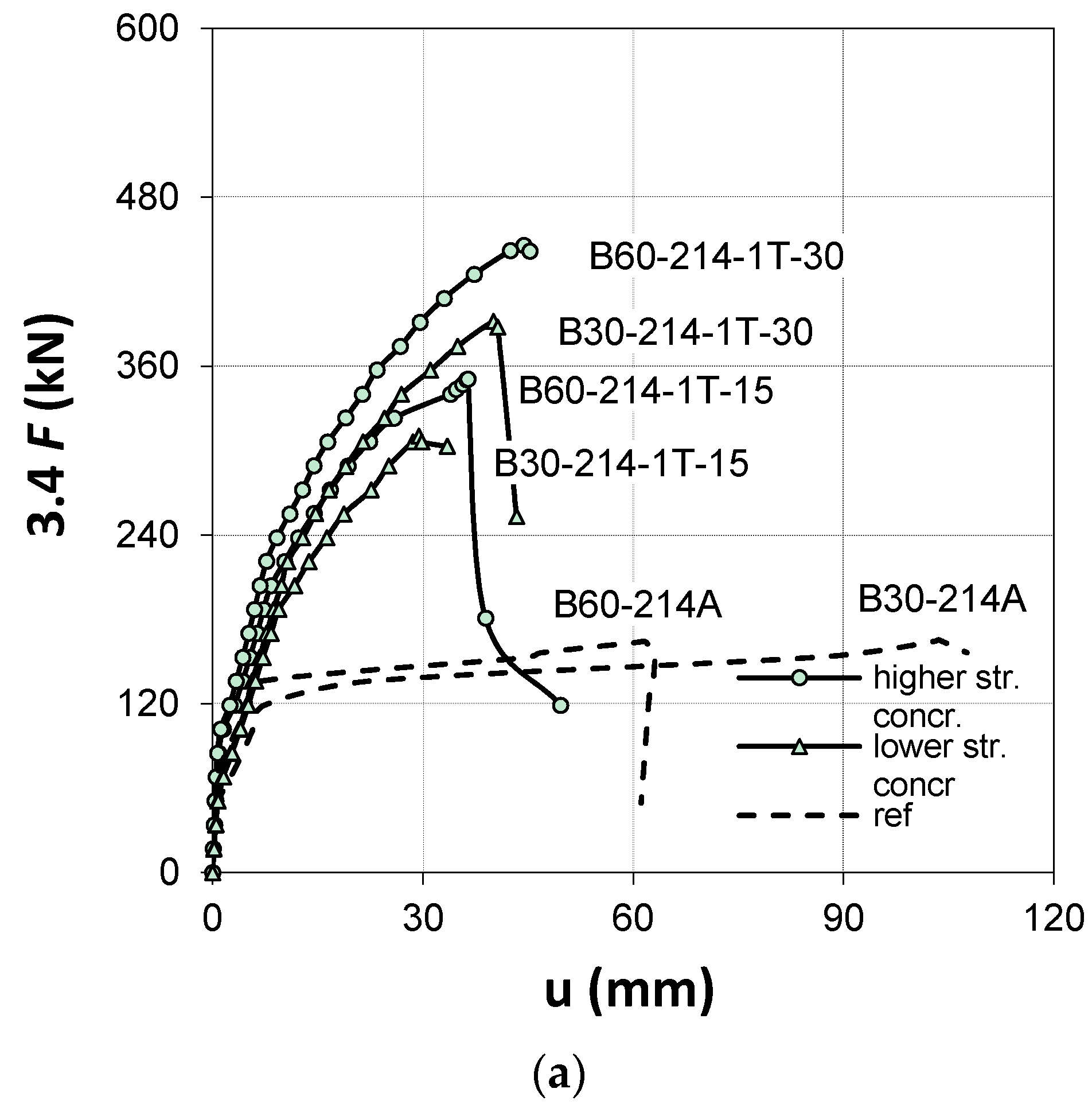
3.3. Force-Deflection Relationships


| No. | Symbol | 3.4 F | |||||||
|---|---|---|---|---|---|---|---|---|---|
| 85 kN | 119 kN | 170 kN | 225 kN | 340 kN | 425 kN | 510 kN | |||
| 1 | B30-214-A | ultimate deflection at the load level (mm) | 5.0 | 6.0 | - | - | - | - | - |
| 2 | B30-214-1T-15 | 3.0 | 5.0 | 8.0 | 19.0 | - | - | - | |
| 3 | B30-214-2T-15 | 3.0 | 4.0 | 6.0 | 11.0 | 19.0 | - | - | |
| 4 | B30-214-1T-30 | 2.5 | 5.0 | 7.5 | 14.5 | 27.0 | - | - | |
| 5 | B60-214-A | 2.0 | 5.0 | - | - | - | - | - | |
| 6 | B60-214-1T-15 | <1.0 1 | 3.0 | 6.5 | 14.5 | 34.0 | - | - | |
| 7 | B60-214-2T-15 | <1.0 1 | 2.0 | 4.5 | 8.5 | 14.5 | 23.5 | - | |
| 8 | B60-214-1T-30 | 0.5 1 | 2.5 | 5.0 | 10.0 | 20.0 | 37.5 | - | |
| 9 | B60-214-2T-30 | <1.0 1 | 1.5 | 4.0 | 8.0 | 12.0 | 18.0 | 25.0 | |
3.4. Force-Strain Relationship

4. Conclusions
Acknowledgments
Author Contributions
Conflicts of Interest
References
- Kotynia, R.; Baky, H.A.; Neale, K.W.; Ebead, U.A. Flexural strengthening of RC beams with externally bonded CFRP systems: Test results and 3-D nonlinear FE analysis. J. Compos. Constr. 2008, 12, 190–201. [Google Scholar] [CrossRef]
- Bank, L.C.; Borowicz, D.T.; Arora, D.; Lamanna, A.J.; Ray, J.C.; Velazquez, G.I. Strengthening of Concrete Beams with Fasteners and Composite Material Strips—Scaling and Anchorage Issues; Report ERDC/GSL TR-04-5; US Army Corps of Engineers: Washington, DC, USA; p. 154.
- Del Vecchio, C.; di Ludovico, M.; Balsamo, A.; Prota, A.; Manfredi, G.; Dolce, M. Experimental investigation of exterior RC beam-column joints retrofitted with FRP systems. J. Compos. Constr. 2014, 18, 04014002. [Google Scholar] [CrossRef]
- Blaschko, M.; Zilch, K. Rehabilitation of concrete structures with CFRP strips glued into slits. In Proceedings of the 12th International Conference on Composite Materials, Paris, France, 5–9 July 1999.
- De Lorenzis, L.; Rizzo, A.; la Tegola, A. A modified pull-out test for bond of near surface mounted FRP rods in concrete. Compos. B 2002, 33, 589–603. [Google Scholar] [CrossRef]
- Blaschko, M. Bond behaviour of CFRP strips glued into slits. In World Scientific, Proceedings of the 6th International Symposium on FRPRCS, Singapore, 8–10 July 2003; Tan, K.H., Ed.; World Scientific Publishing: Singapore city, Singapore, 2003; pp. 205–214. [Google Scholar]
- Taljsten, B.; Carolin, A.; Nordin, H. Concrete structures strengthened with near surface mounted reinforcement of CFRP. Adv. Struct. Eng. 2003, 6, 201–213. [Google Scholar] [CrossRef]
- Hassan, T.; Rizkalla, S. Investigation of bond in concrete structures strengthened with near surface mounted carbon fiber reinforced polymer strips. J. Compos. Constr. 2003, 7, 248–257. [Google Scholar] [CrossRef]
- De Lorenzis, L.; Lundgren, K.; Rizzo, A. Anchorage length of near-surface mounted fiber-reinforced polymer bars for concrete strengthening—Experimental investigation and numerical modelling. ACI Struct. J. 2004, 101, 269–278. [Google Scholar]
- Parretti, R.; Nanni, A. Strengthening of RC members using near-surface mounted FRP composites: Design overview. Adv. Struct. Eng. 2004, 7, 469–483. [Google Scholar] [CrossRef]
- De Lorenzis, L. Anchorage length of near-surface mounted fiber reinforced polymer bars for concrete strengthening—Analytical modeling. ACI Struct. J. 2004, 101, 375–386. [Google Scholar]
- El-Hacha, R.; Rizkalla, S. Near-surface-mounted fiber-reinforced polymer reinforcements for flexural strengthening of concrete structures. ACI Struct. J. 2004, 101, 717–726. [Google Scholar]
- Hassan, T.; Rizkalla, S. Bond mechanism of near-surface-mounted fiber reinforced polymer bars for flexural strengthening of concrete structures. ACI Struct. J. 2004, 101, 830–839. [Google Scholar]
- Seracino, R.; Saifulnaz, R.; Oehlers, D. Generic debonding resistance of EB and NSM plate-to-concrete joints. J. Compos. Constr. 2007, 11, 62–70. [Google Scholar] [CrossRef]
- Barros, J.; Fortes, A.S. Flexural strengthening of concrete beams with CFRP laminates bonded into slits. Cem. Concr. Compos. 2005, 27, 471–480. [Google Scholar] [CrossRef]
- Barros, J.; Dias, S. Near surface mounted CFRP laminates for shear strengthening of concrete beams. Cem. Concr. Compos. 2006, 28, 276–292. [Google Scholar] [CrossRef]
- Kotynia, R. Analysis of reinforced concrete beams strengthened with near surface mounted FRP reinforcement. Arch. Civ. Eng. 2006, 52, 305–317. [Google Scholar]
- De Lorenzis, L.; Teng, J.G. Near-surface mounted FRP reinforcement: An emerging technique for strengthening structures. Compos. B 2007, 38, 119–143. [Google Scholar] [CrossRef]
- Al-Mahmoud, F.; Castel, A.; François, R.; Tourneur, C. Strengthening of RC members with near-surface mounted CFRP rods. Compos. Struct. 2009, 91, 138–147. [Google Scholar] [CrossRef]
- Islam, A. Effective methods of using CFRP bars in shear strengthening of concrete girders. Eng. Struct. 2009, 31, 709–714. [Google Scholar] [CrossRef]
- Rasheed, H.; Harrison, R.; Peterman, R.; Alkhrdaji, T. Ductile strengthening using externally bonded and near surface mounted composite systems. Compos. Struct. 2010, 92, 2379–2390. [Google Scholar] [CrossRef]
- Barros, A.; Ferreira, D.; Fortes, A.; Dias, S. Assessing the effectiveness of embedding CFRP laminates in the near surface for structural strengthening. Constr. Build. Mater. 2006, 20, 478–491. [Google Scholar] [CrossRef]
- Teng, J.; de Lorenzis, L.; Wang, B.; Li, R.; Wong, T.; Lam, L. Debonding failures of RC beams strengthened with near surface mounted CFRP strips. J. Compos. Constr. 2006, 10, 92–105. [Google Scholar] [CrossRef]
- Yost, J.; Gross, S.; Dinehart, D.; Mildenberg, J. Flexural behaviour of concrete beams strengthened with near-surface-mounted CFRP strips. ACI Struct. J. 2007, 104, 430–437. [Google Scholar]
- Costa, I.G.; Barros, J.A.O. Flexural and shear strengthening of RC beams with composites materials—The influence of cutting steel stirrups to install CFRP strips. Cem. Concr. Compos. 2010, 32, 544–553. [Google Scholar] [CrossRef]
- Kotynia, R. Bond between FRP and concrete in reinforced concrete beams strengthened with near surface mounted and externally bonded reinforcement. Constr. Build. Mater. 2012, 32, 41–54. [Google Scholar] [CrossRef]
- MacGregor, J.G.; Wight, J.K. Reinforced Concrete Mechanics and Design, 6th ed.; Pearson Education, Inc.: Upper Saddle River, NJ, USA, 2012; p. 1157. [Google Scholar]
© 2015 by the authors; licensee MDPI, Basel, Switzerland. This article is an open access article distributed under the terms and conditions of the Creative Commons by Attribution (CC-BY) license (http://creativecommons.org/licenses/by/4.0/).
Share and Cite
Kotynia, R.; Cholostiakow, S. New Proposal for Flexural Strengthening of Reinforced Concrete Beams Using CFRP T-Shaped Profiles. Polymers 2015, 7, 2461-2477. https://doi.org/10.3390/polym7111524
Kotynia R, Cholostiakow S. New Proposal for Flexural Strengthening of Reinforced Concrete Beams Using CFRP T-Shaped Profiles. Polymers. 2015; 7(11):2461-2477. https://doi.org/10.3390/polym7111524
Chicago/Turabian StyleKotynia, Renata, and Szymon Cholostiakow. 2015. "New Proposal for Flexural Strengthening of Reinforced Concrete Beams Using CFRP T-Shaped Profiles" Polymers 7, no. 11: 2461-2477. https://doi.org/10.3390/polym7111524
APA StyleKotynia, R., & Cholostiakow, S. (2015). New Proposal for Flexural Strengthening of Reinforced Concrete Beams Using CFRP T-Shaped Profiles. Polymers, 7(11), 2461-2477. https://doi.org/10.3390/polym7111524