
Effect of Thermal Distress on Residual Behavior of CFRP-Strengthened Steel Beams Including Periodic Unbonded Zones


Abstract
:
1. Introduction
2. Research Significance
3. Methodology
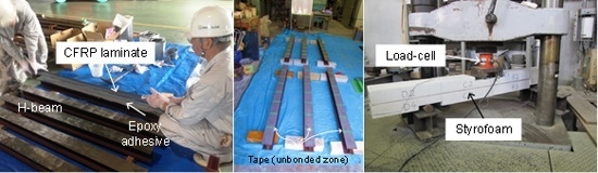
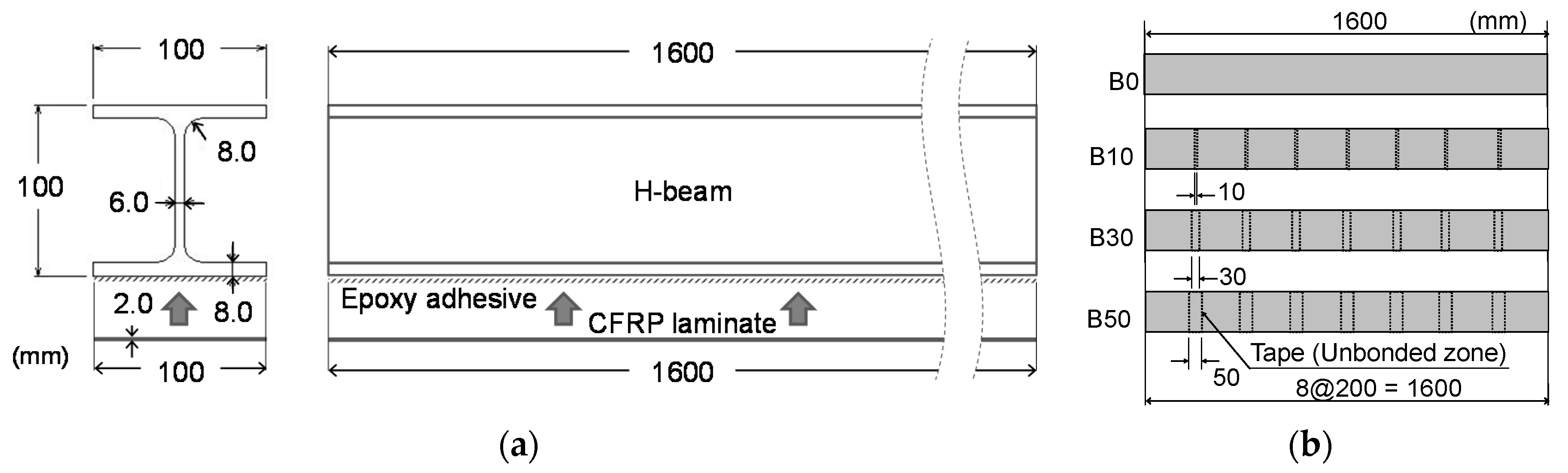
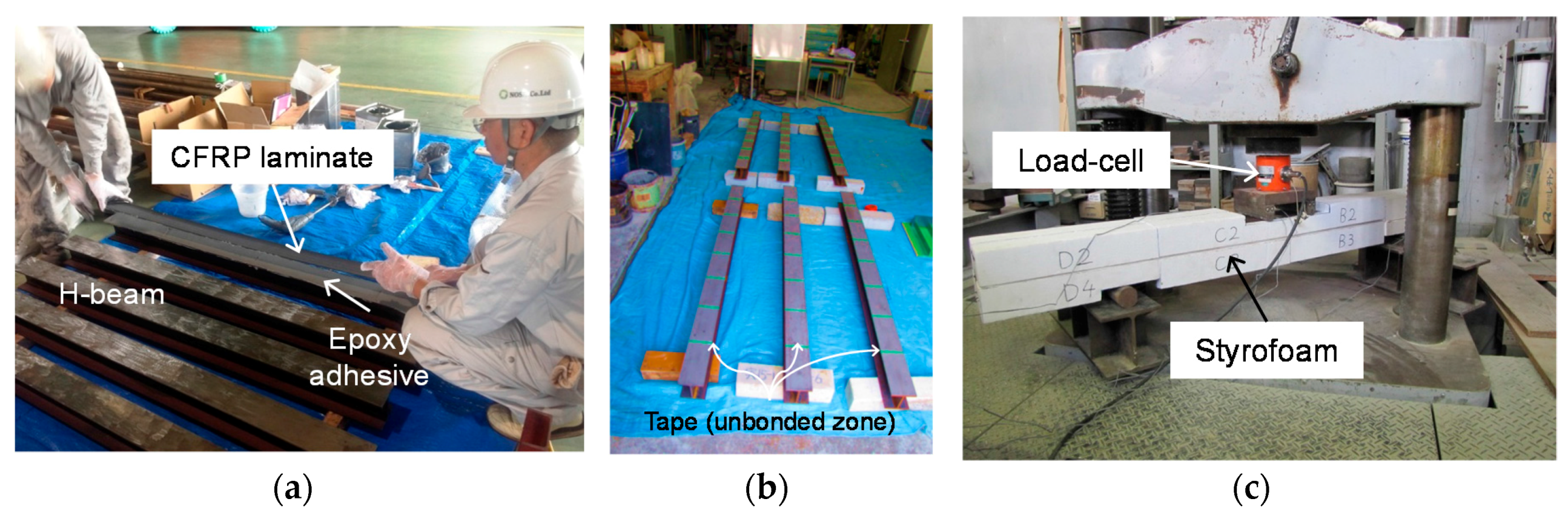
3.1. Test Specimens


| Properties | H-Beam | CFRP laminate |
|---|---|---|
| Yield strength or tensile strength | 245 MPa | 1628 MPa |
| Young’s modulus | 200 GPa | 480 GPa |
| Poisson’s ratio | 0.3 | 0.3 |
| Coefficient of thermal expansion (CTE) | 12.0 × 10⁻⁶/°C | 0.3 × 10⁻⁶/°C |
| Properties | Value |
|---|---|
| Density | 1.7 g/cm3 |
| Unit weight | 375 g/m2 |
| Useable bonding time | 84 min |
| Shear strength | 16.0 MPa |
| Bond strength | 3.7 MPa |
| Compressive strength | 65 MPa |
| Young’s modulus | 4.9 GPa |
| Poisson’s ratio | 0.4 |
| Coefficient of thermal expansion | 68 × 10−6/°C |
| Identification | Number of Beams Tested | Unbonded Zone | Flexural Test Time |
|---|---|---|---|
| Control | 1 | N/A | at 0 day |
| B0 | 3 | None | at 0, 28, 84 days |
| B10 | 3 | 7@100 × 10 mm | at 0, 28, 84 days |
| B30 | 3 | 7@100 × 30 mm | at 0, 28, 84 days |
| B50 | 3 | 7@100 × 50 mm | at 0, 28, 84 days |
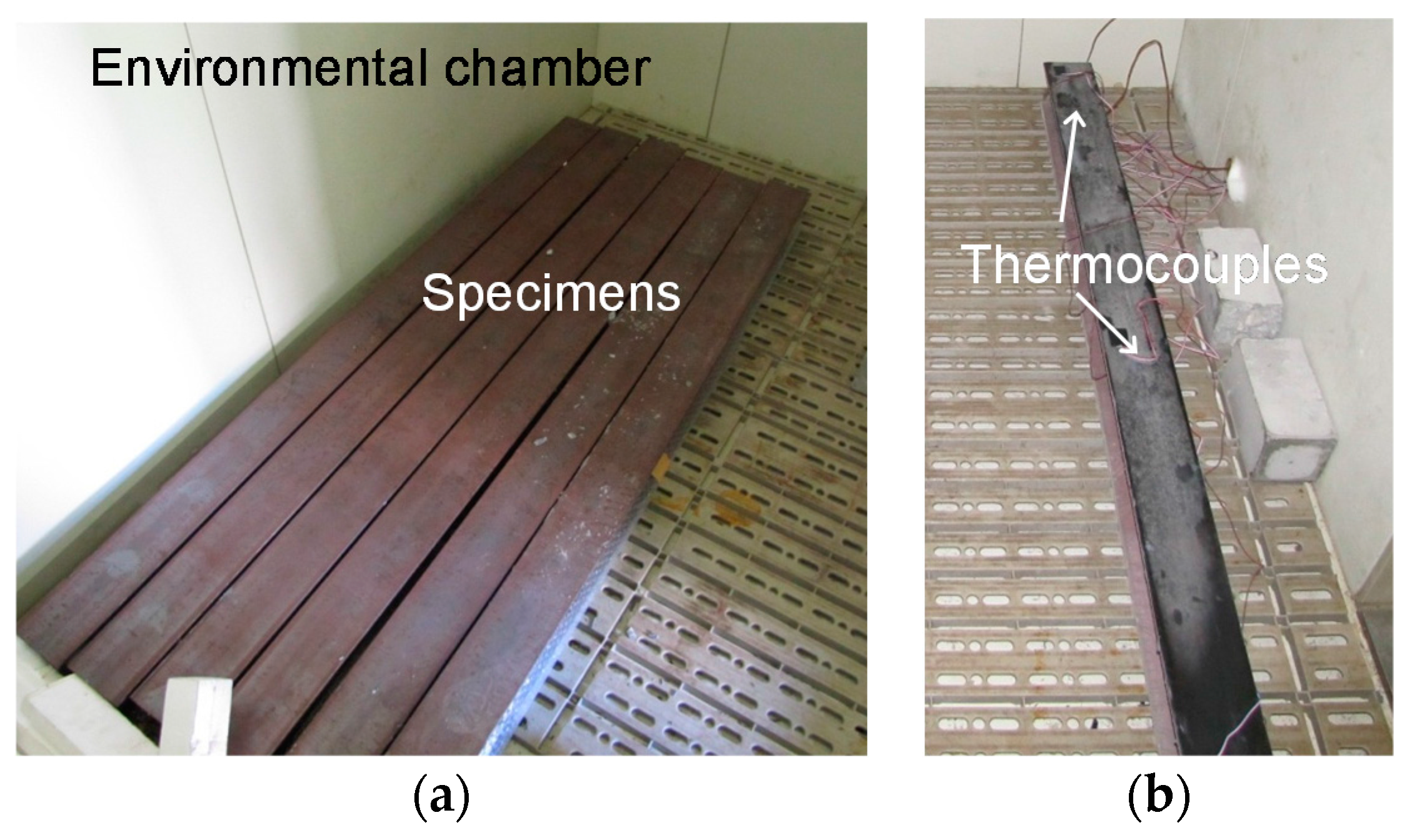
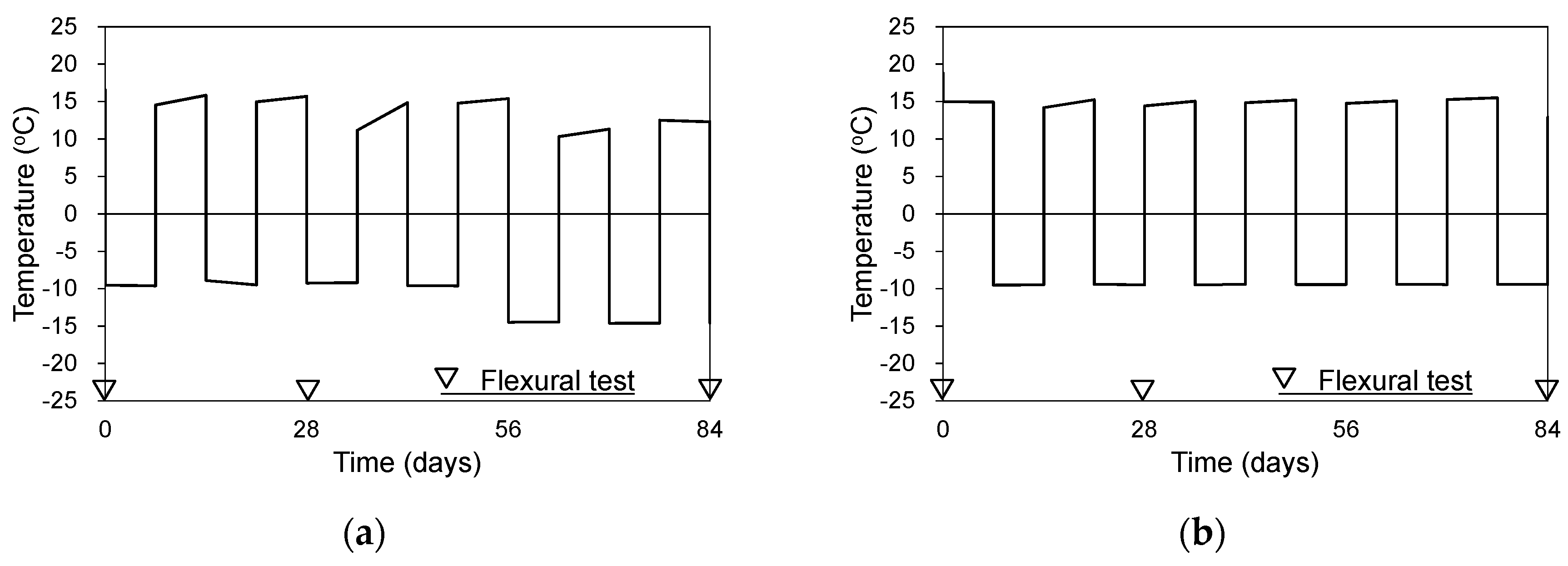
3.2. Temperature Cycling


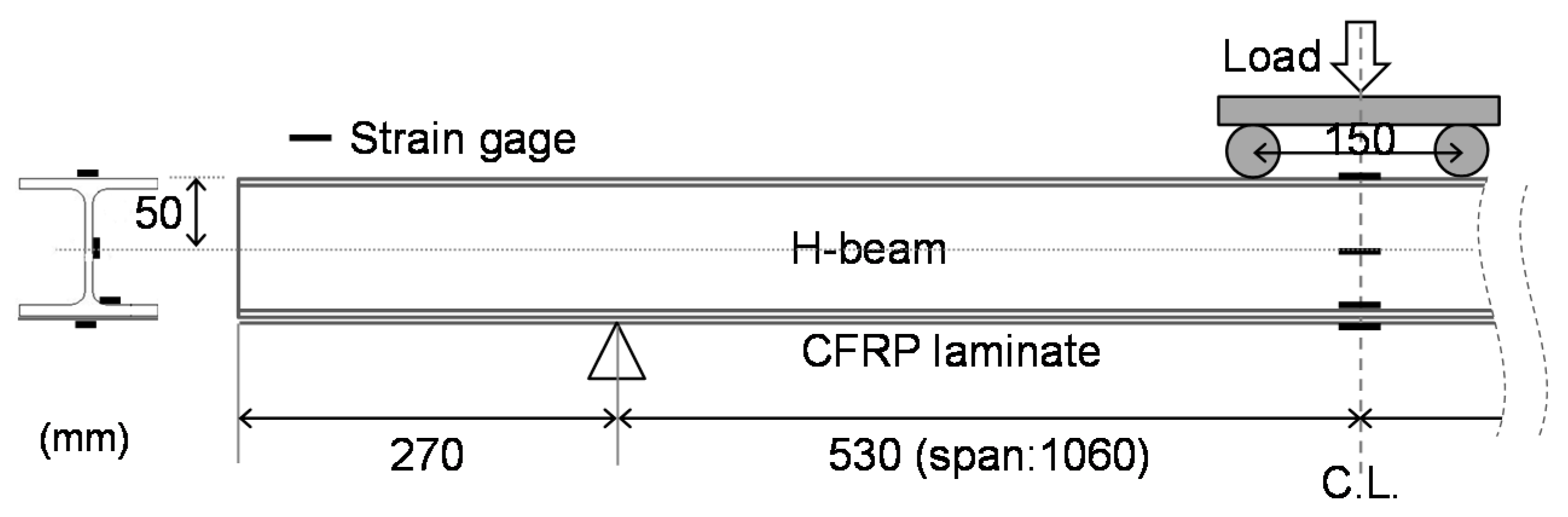
3.3. Flexural Test
4. Results and Discussion
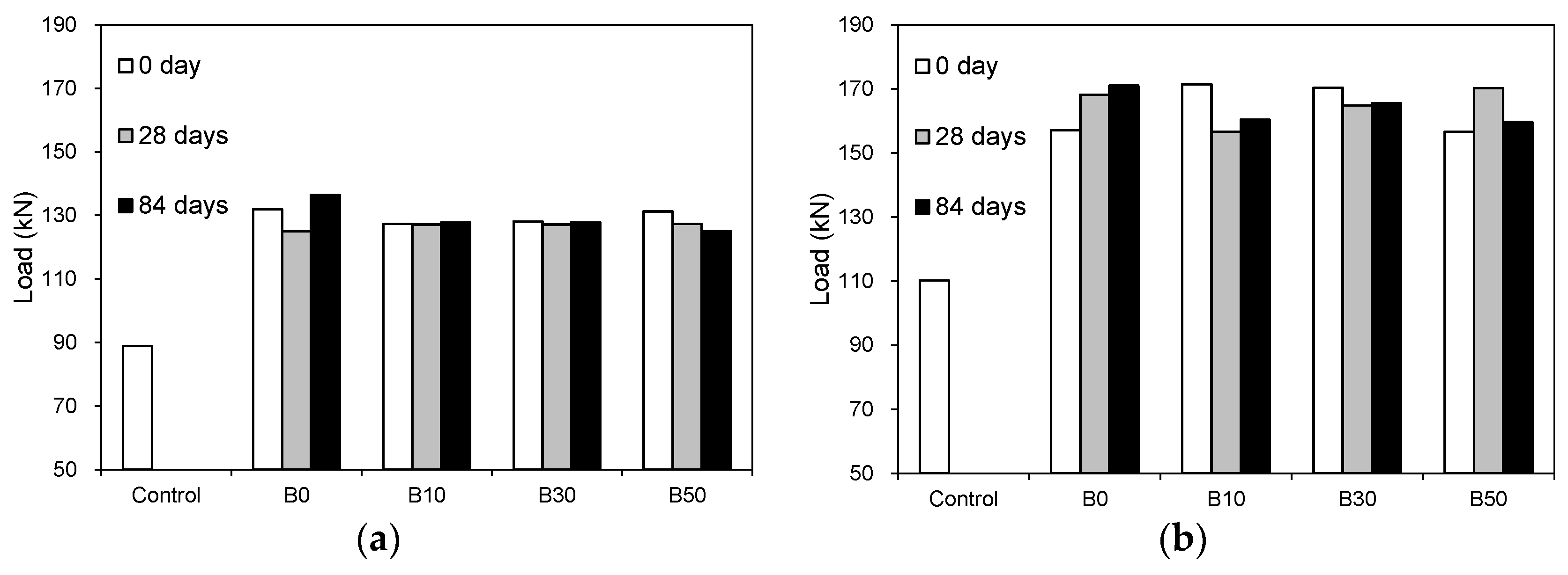
4.1. Residual Capacity

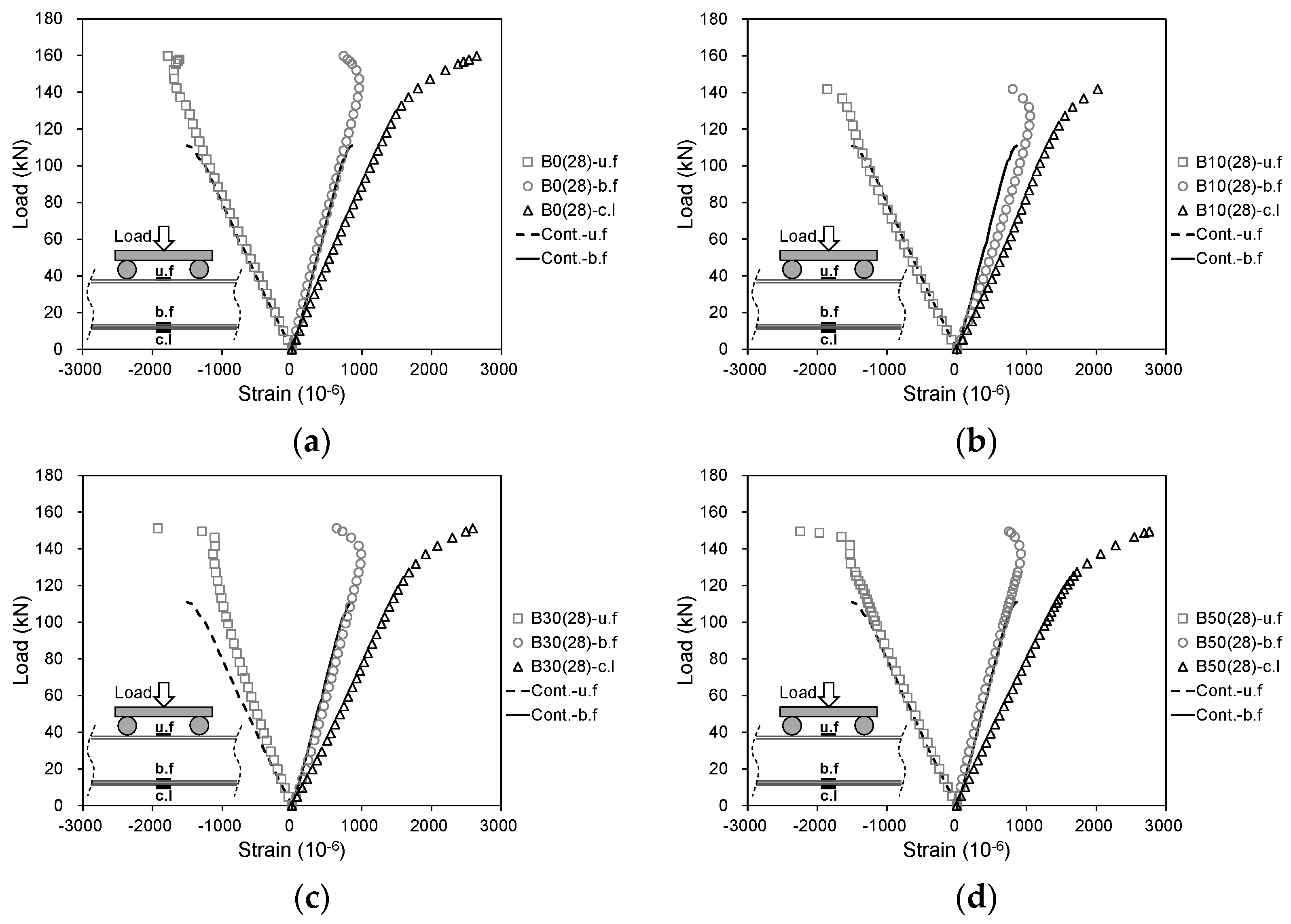
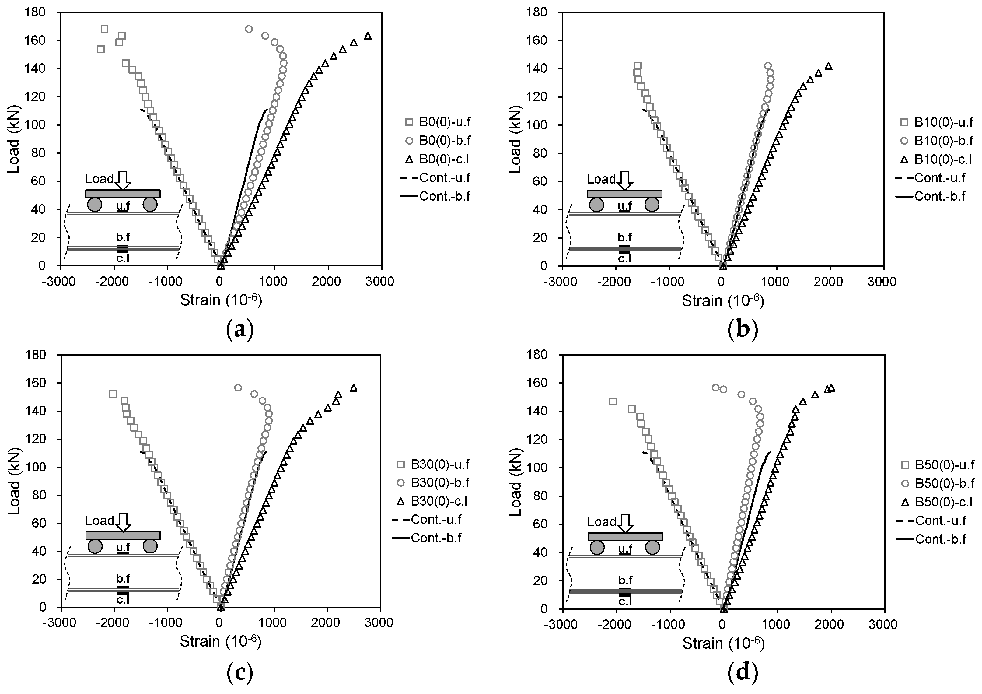
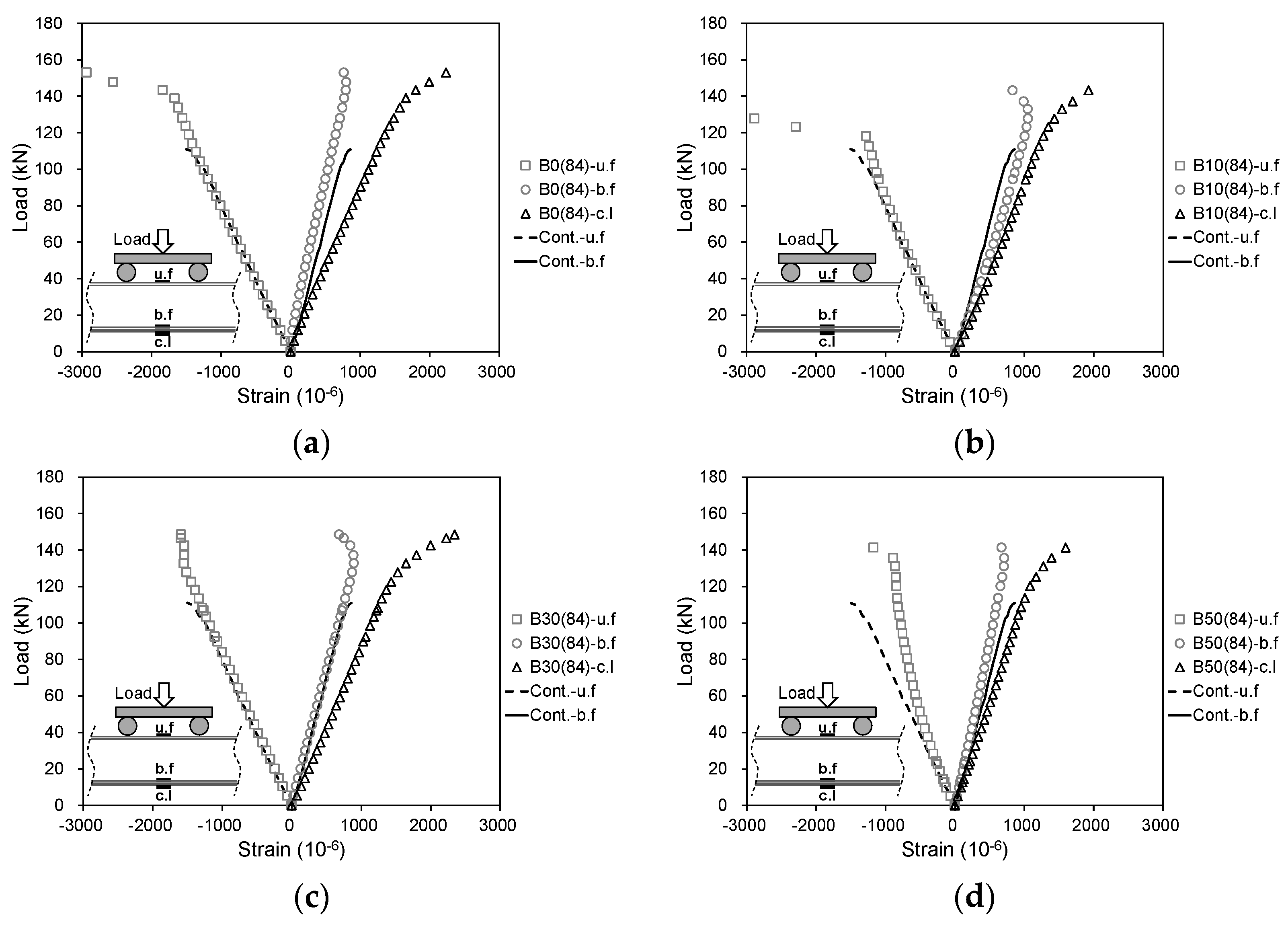
4.2. Load-Strain Behavior

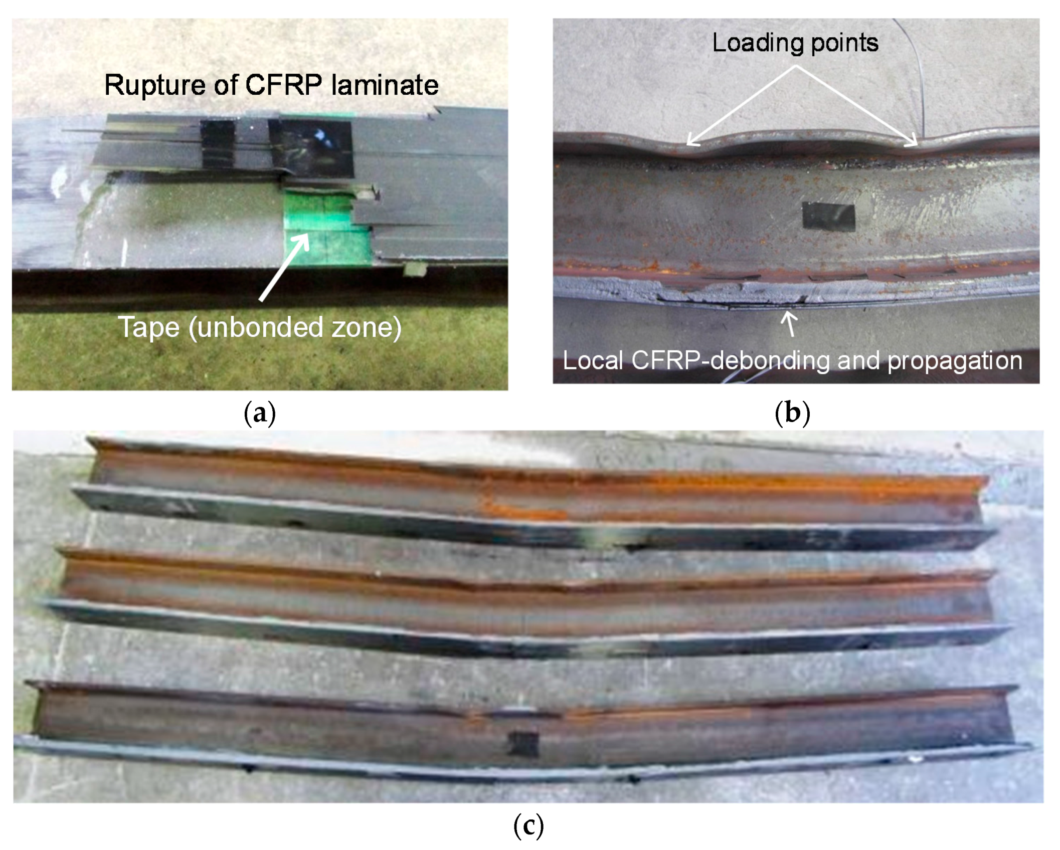
4.3. Failure Mode

5. Predictive Assessment
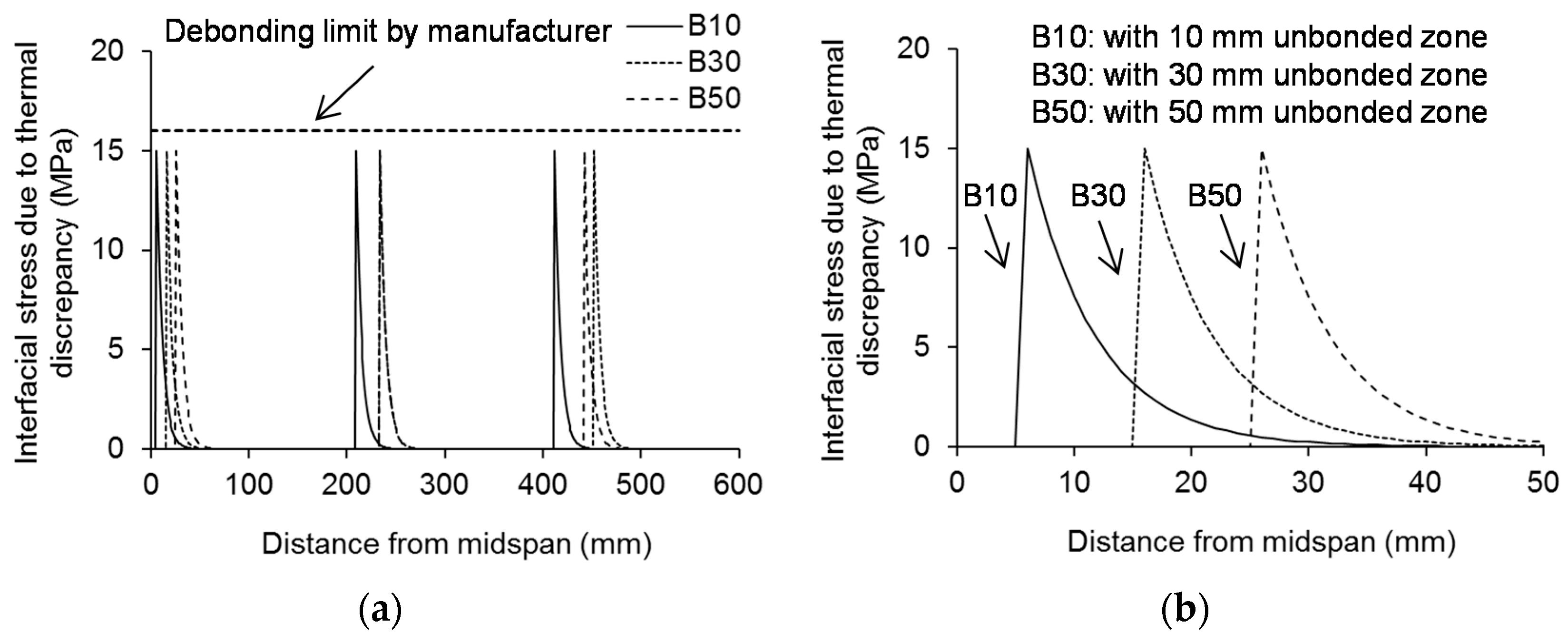
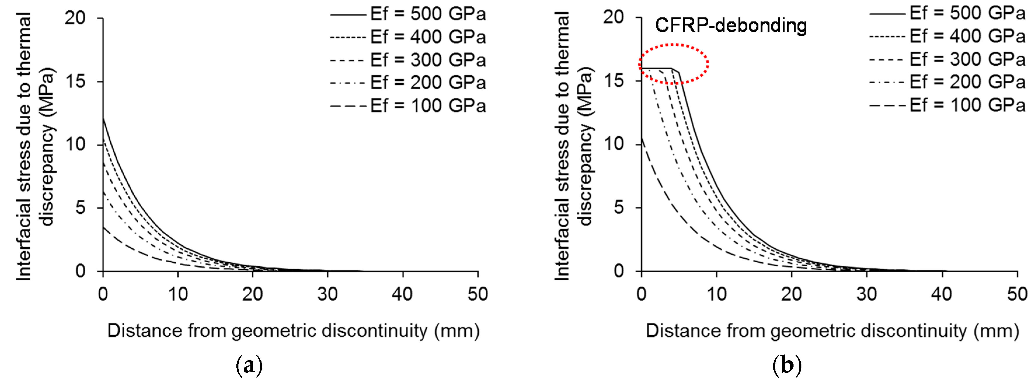
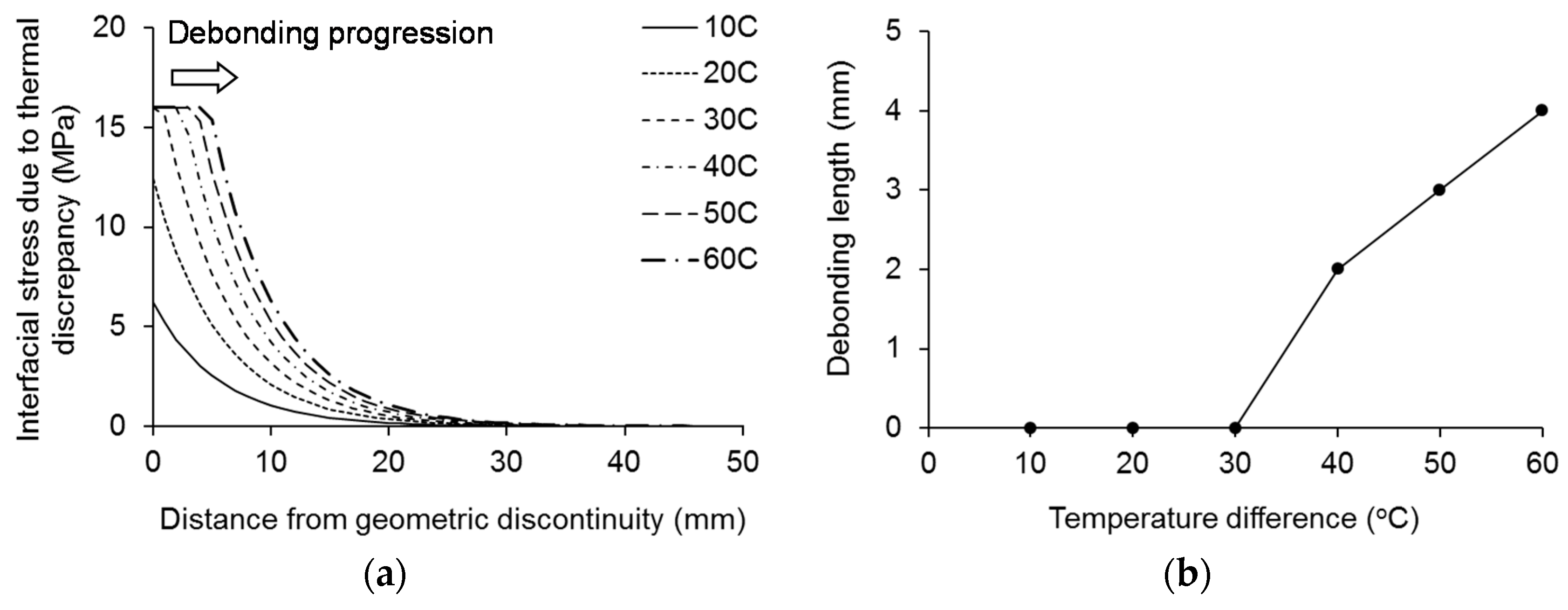
5.1. Interfacial Stress Development
5.2. Predicted Stress Profile


6. Summary and Conclusions
- The composite action between the CFRP and the substrate was maintained until the strengthened beams were loaded to yielding, irrespective of the extent of thermal cycling and the size of unbonded zones along the interface. With an increase in load level, local damage took place at the geometric discontinuities adjacent to the unbonded zones, and CFRP debonding initiated and progressed.
- The failure of the strengthened beams was attributed to a combination of local flange yielding and CFRP rupture, while the thermal distress effect of ΔT = 25 °C was found to be insignificant. The degree of initial bond defect represented by the unbonded zones appeared to be influential on stress transfer from the steel to the CFRP as the load stage shifted from yielding to ultimate.
- Periodic interfacial stresses were predicted along the CFRP-steel interface due to the presence of the unbonded zones. Such a prediction theoretically confirmed the thermal behavior of the experimental beams (i.e., no progression of CFRP debonding at ΔT = 25 °C). The parametric study revealed that CFRP debonding occurred at ΔT = 30 °C and progressed as the temperature difference augmented.
- The possible existence of multiple debonding-progression stages associated with the degree of thermal distress was proposed, while further experimental validation was recommended. High-modulus CFRP laminates should restrictively be used for strengthening steel members if a wide temperature variation range (ΔT ≥ 30 °C) is anticipated.
Acknowledgments
Author Contributions
Conflicts of Interest
Appendix
References
- Teng, J.G.; Yu, T.; Fernando, D. Strengthening of steel structures with fiber-reinforced polymer composites. J. Constr. Steel Res. 2012, 78, 131–143. [Google Scholar] [CrossRef]
- Adams, R.D. Adhesive Bonding: Science Technology and Applications; Woodhead Publishing: Cambridge, UK, 2005. [Google Scholar]
- Al-Shawaf, A.; Zhao, X.-L. Adhesive rheology impact on wet lay-up CFRP/steel joints’ behaviour under infrastructure subzero exposures. Compos. B Eng. 2013, 47, 207–219. [Google Scholar] [CrossRef]
- Dawood, M.; Rizkalla, S. Environmental durability of a CFRP system for strengthening steel structures. Constr. Build. Mater. 2010, 24, 1682–1689. [Google Scholar] [CrossRef]
- Al-Shawaf, A. Modelling wet lay-up CFRP-steel bond failures at extreme temperatures using stress-based approach. Int. J. Adhes. Adhes. 2011, 31, 416–428. [Google Scholar] [CrossRef]
- Nguyen, T.-C.; Bai, Y.; Al-Mahaidi, R.; Zhao, X.-L. Time-dependent behaviour of steel/CFRP double strap joints subjected to combined thermal and mechanical loading. Compos. Struct. 2012, 94, 1826–1833. [Google Scholar] [CrossRef]
- Rabinovitch, O. Impact of thermal loads on interfacial debonding in FRP strengthened beams. Int. J. Solids Struct. 2010, 47, 3234–3244. [Google Scholar] [CrossRef]
- Gao, W.Y.; Teng, J.G.; Dai, J.G. Effect of temperature variation on the full-range behavior of FRP-to-concrete bonded joints. ASCE J. Compos. Constr. 2012, 16, 671–683. [Google Scholar] [CrossRef]
- Gao, W.Y.; Dai, J.G.; Teng, J.G. Analysis of Mode II debonding behavior of fiber-reinforced polymer-to-substrate bonded joints subjected to combined thermal and mechanical loading. Eng. Fract. Mech. 2015, 136, 241–264. [Google Scholar] [CrossRef]
- Yoshitake, I.; Tsuda, H.; Itose, J.; Hisabe, N. Effect of discrepancy in thermal expansion coefficients of CFRP and steel under cold temperature. Constr. Build. Mater. 2014, 59, 17–24. [Google Scholar] [CrossRef]
- Okura, I.; Fukui, T.; Nakamura, K.; Matsugami, T. Decrease in stress in steel plates by carbon fiber sheets and debonding shearing stress. Doboku Gakkai Ronbunshu 2001, 689, 239–249. (In Japanese) [Google Scholar] [CrossRef] [Green Version]
- Tsuda, H. Experimental Study on Bond Properties of Carbon Fiber Reinforced Polymer (CFRP) Laminate Glued to Steel Substrate under Cold Temperature. Ph.D. Thesis, Yamaguchi University, Ube, Japan, March 2015. [Google Scholar]
© 2015 by the authors; licensee MDPI, Basel, Switzerland. This article is an open access article distributed under the terms and conditions of the Creative Commons by Attribution (CC-BY) license (http://creativecommons.org/licenses/by/4.0/).
Share and Cite
Yoshitake, I.; Tsuda, H.; Kim, Y.J.; Hisabe, N. Effect of Thermal Distress on Residual Behavior of CFRP-Strengthened Steel Beams Including Periodic Unbonded Zones. Polymers 2015, 7, 2332-2343. https://doi.org/10.3390/polym7111517
Yoshitake I, Tsuda H, Kim YJ, Hisabe N. Effect of Thermal Distress on Residual Behavior of CFRP-Strengthened Steel Beams Including Periodic Unbonded Zones. Polymers. 2015; 7(11):2332-2343. https://doi.org/10.3390/polym7111517
Chicago/Turabian StyleYoshitake, Isamu, Hisatsugu Tsuda, Yail J. Kim, and Nobuhiro Hisabe. 2015. "Effect of Thermal Distress on Residual Behavior of CFRP-Strengthened Steel Beams Including Periodic Unbonded Zones" Polymers 7, no. 11: 2332-2343. https://doi.org/10.3390/polym7111517
APA StyleYoshitake, I., Tsuda, H., Kim, Y. J., & Hisabe, N. (2015). Effect of Thermal Distress on Residual Behavior of CFRP-Strengthened Steel Beams Including Periodic Unbonded Zones. Polymers, 7(11), 2332-2343. https://doi.org/10.3390/polym7111517