
Flexural Strengthening of RC Slabs with Prestressed CFRP Strips Using Different Anchorage Systems †


Abstract
:1. Introduction
2. Experimental Program
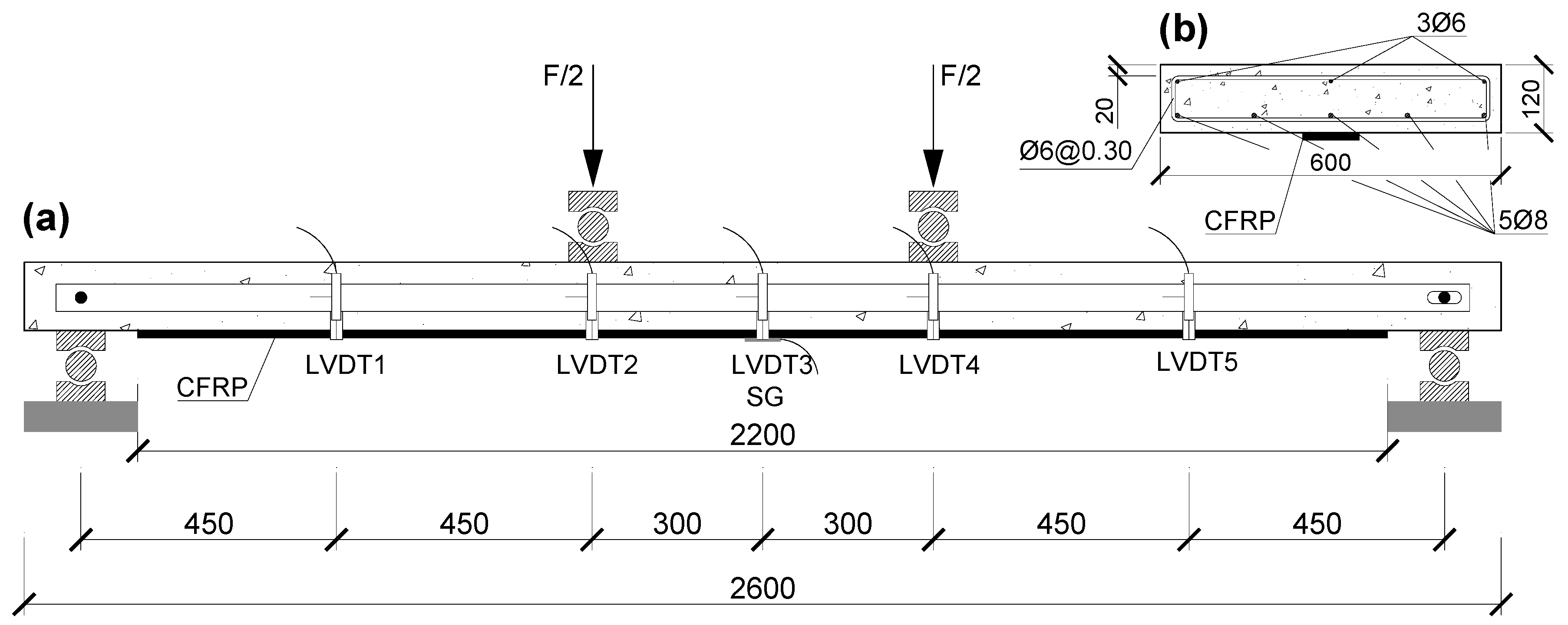
2.1. Test Program

| Slab | CFRP Strip (bf × tf) | Anchorage | εf,p (‰) | fcm (MPa) | Ecm (GPa) |
|---|---|---|---|---|---|
| REF1 | - | - | - | 53.4 (4.3%) | 32.2 (7.5%) |
| REF2 | - | - | - | 57.4 (3.0%) | 32.6 (0.1%) |
| SL50_1.4_EBR | 50 mm × 1.4 mm | - | - | 53.4 (4.3%) | 32.2 (7.5%) |
| SL50_1.4_MA | 50 mm × 1.4 mm | MA | 3.98 | 53.4 (4.3%) | 32.2 (7.5%) |
| SL50_1.4_GA | 50 mm × 1.4 mm | GA | 4.05 | 53.4 (4.3%) | 32.2 (7.5%) |
| SL50_1.2_MA | 50 mm × 1.2 mm | MA | 4.19 | 49.5 (3.1%) | - |
| SL80_1.2_MA | 80 mm × 1.2 mm | MA | 3.99 | 57.4 (3.0%) | 32.6 (0.1%) |
| SL80_1.2_GA | 80 mm × 1.2 mm | GA | 4.06 | 57.4 (3.0%) | 32.6 (0.1%) |
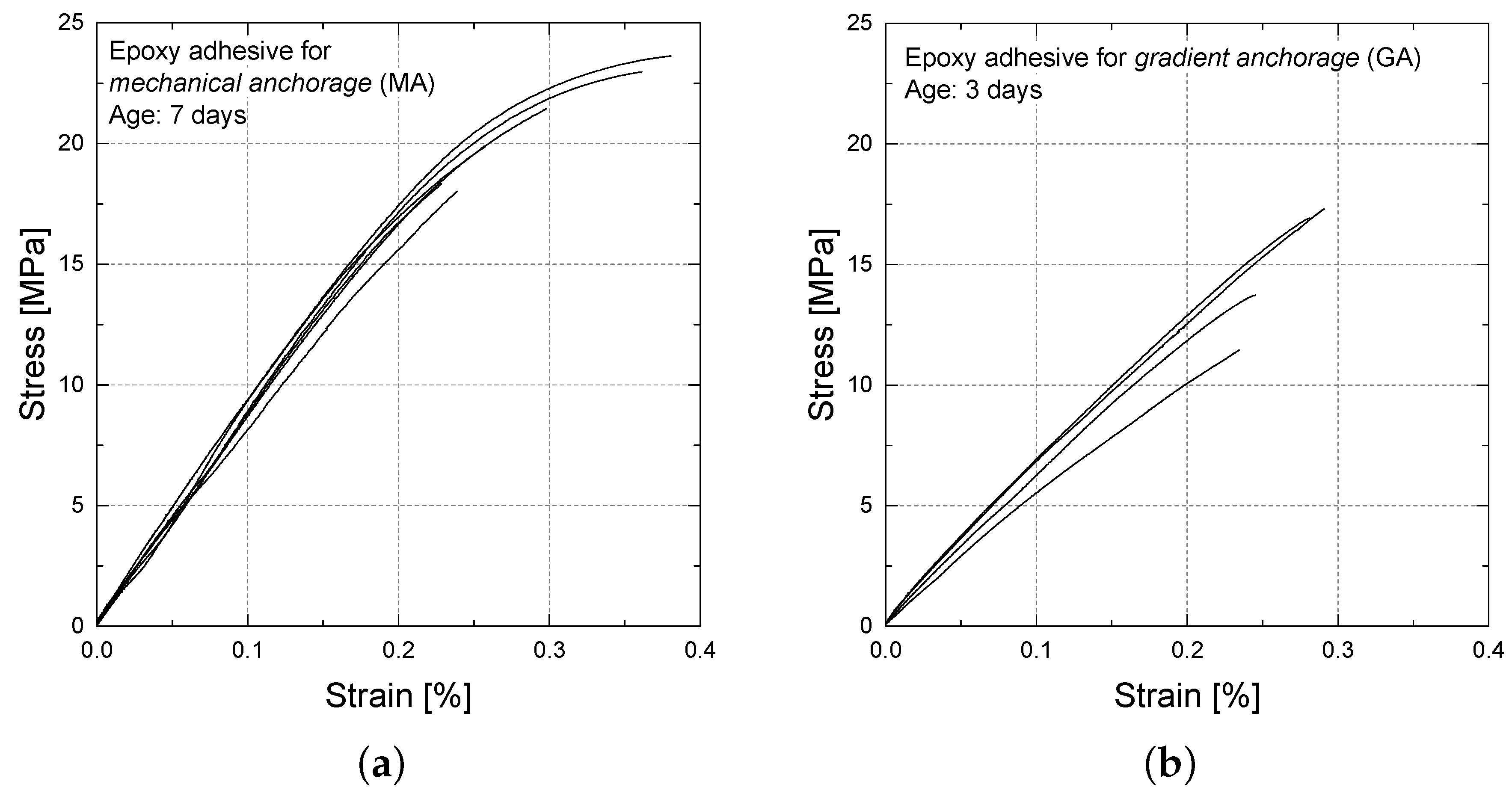
2.2. Materials
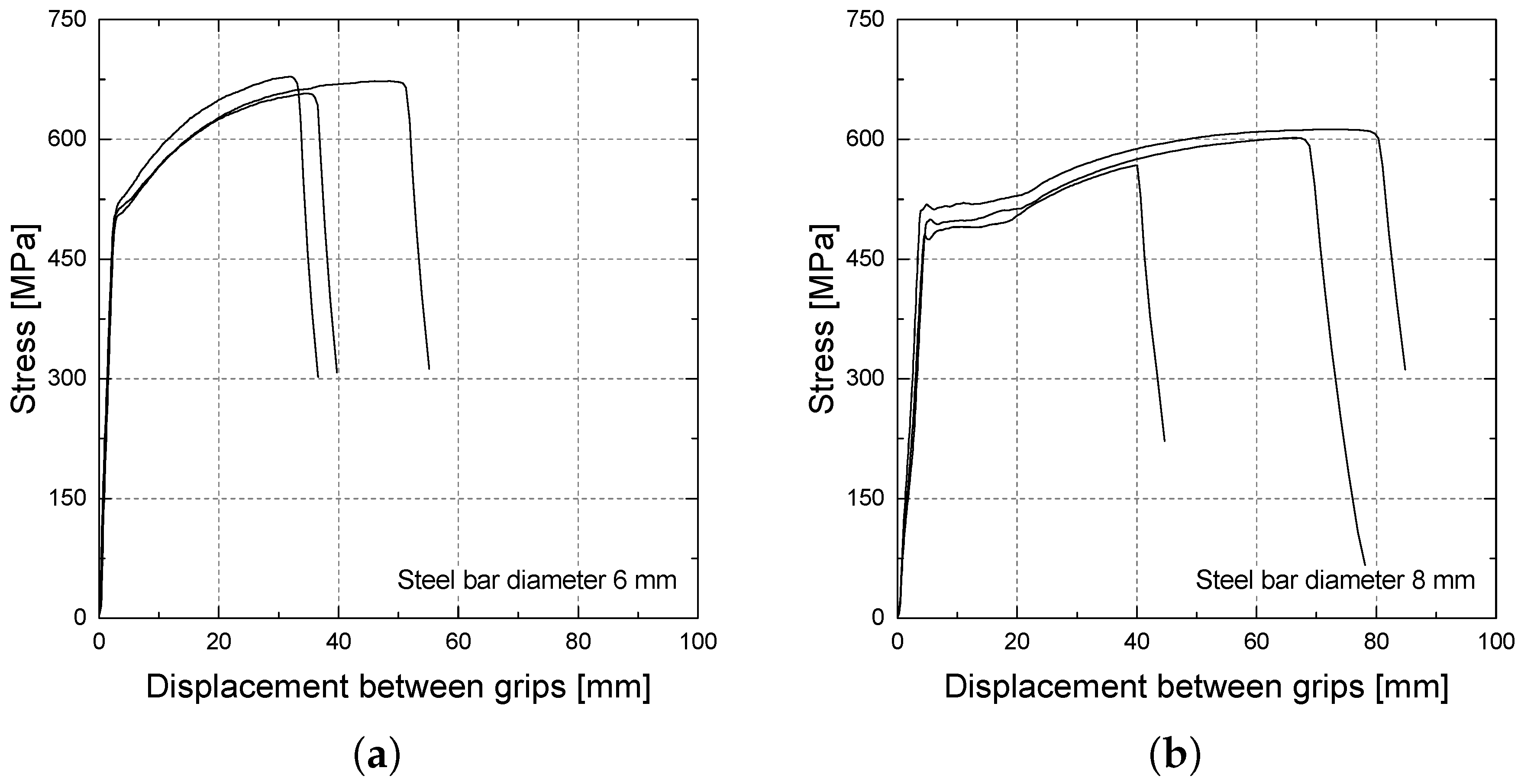
| Bar Type (∅in (mm)) | Es (GPa) | fy (MPa) | fs,u (MPa) |
|---|---|---|---|
| ∅6 | 209.5 (8.5%) | 579.3 (3.3%) | 669.7 (1.7%) |
| ∅8 | 212.8 (9.7%) | 501.4 (5.9%) | 593.9 (3.9%) |
| Geometry (mm × mm) | Ef (GPa) | ff,u (MPa) |
|---|---|---|
| 50 × 1.2 | 167.7 (2.9%) | 2,943.5 (1.6%) |
| 50 × 1.4 | 154.8 (4.6%) | 2,457.1 (1.2%) |
| 80 × 1.2 | 164.6 (0.2%) | 2,455.3 (5.0%) |
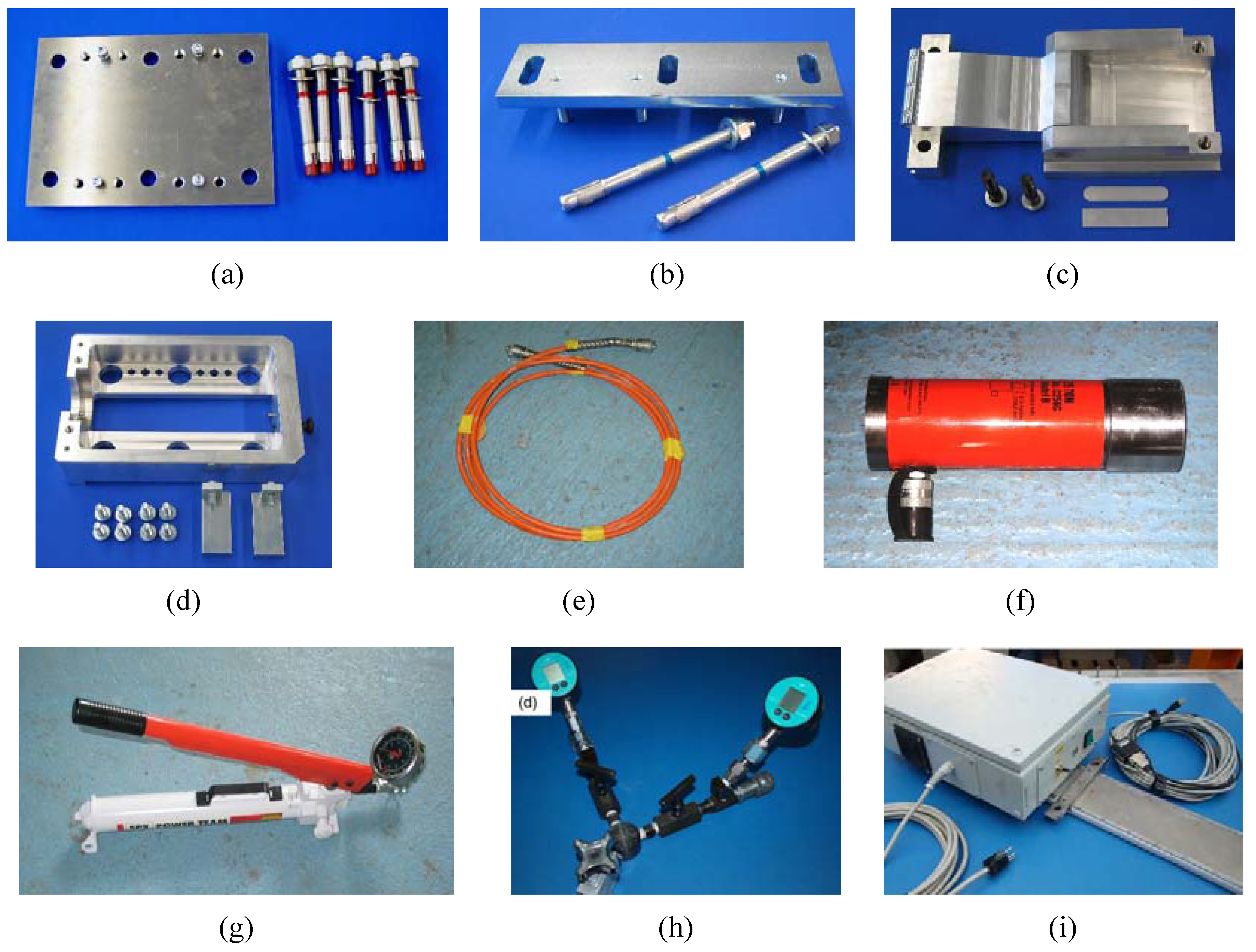
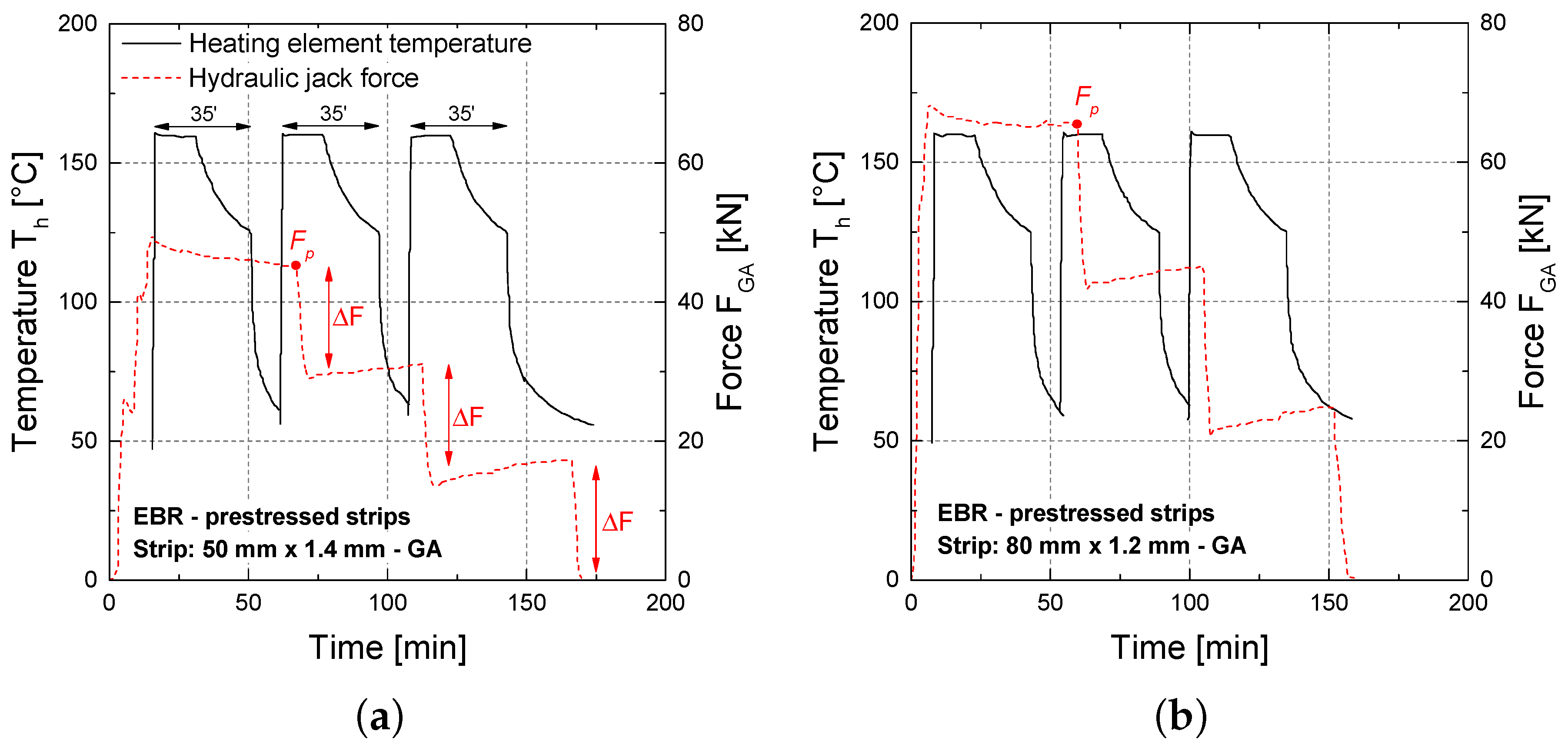
2.3. End-Anchorage
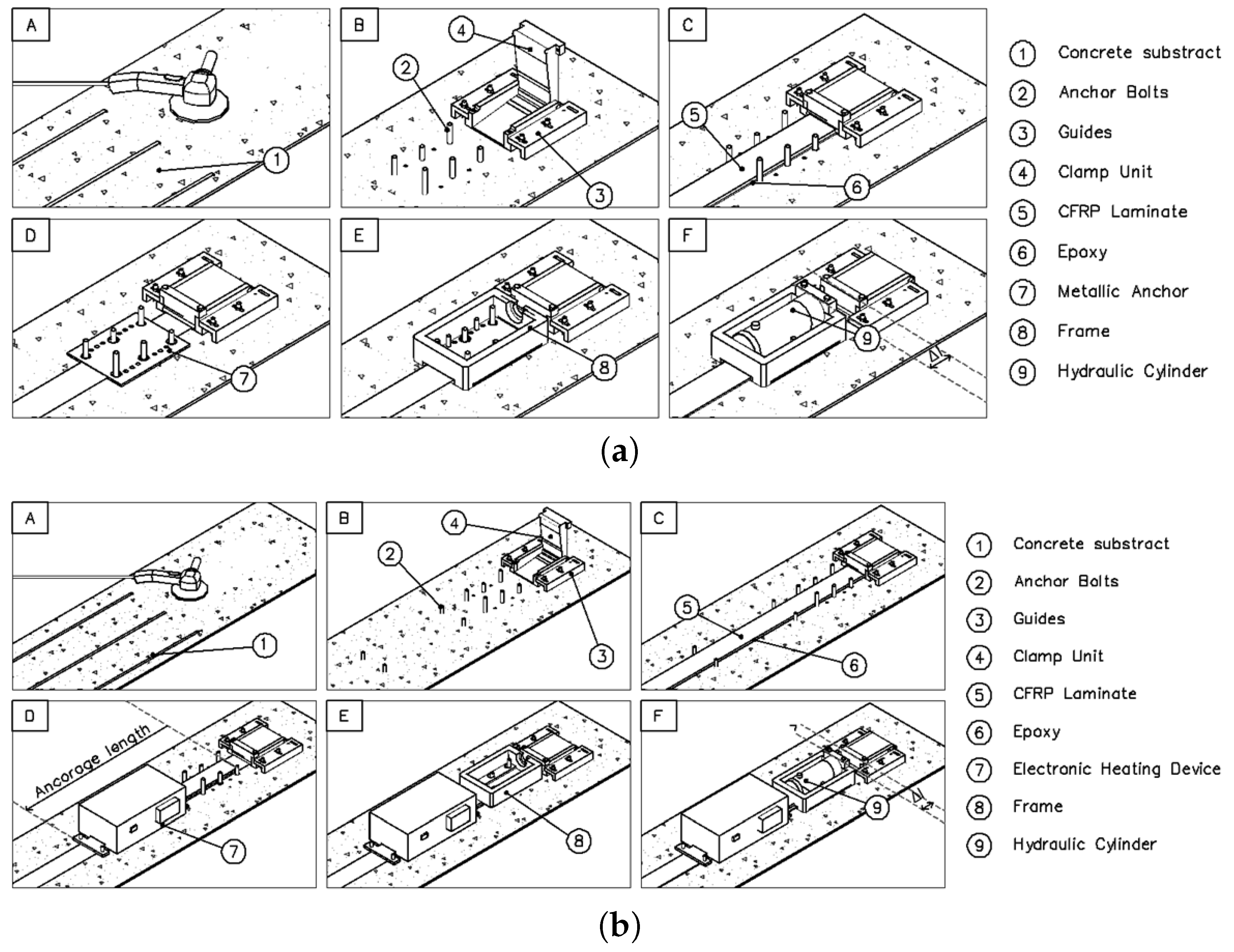
2.3.1. Anchorage Systems


2.3.2. Strengthening Procedure
- (A)
- The first step consists on surface preparation of the slabs where the CFRP laminate strip will be applied. In the present case a grinding stone wheel is used. Subsequently, compressed air was used to clean the treated region.
- (B)
- Several holes are drilled to accommodate temporary and permanent bolt anchors. GA system complies only temporary bolts, while for the case of MA system, six M16 8.8 permanent bolt anchors are used to fix each metallic anchorage plate. The HIT-HY 200-A® chemical bond agent was used to fix these bolts to concrete. Then, aluminium guides are placed in the right position to guide and fix the clamp units. Afterwards the clamp units are placed in its position, i.e., in-between the guides at each extremity of the slab.
- (C)
- The CFRP laminate strip is cleaned with a solvent and the epoxy adhesive is prepared according to the information given by the producer’s technical datasheet. It should be remarked that before this step, the CFRP laminate strip had been already instrumented with a strain gauge at its mid-length (see also Section 2.1). Subsequently, the adhesive is applied on the surface of the CFRP laminate as well as on the concrete surface region in contact with the laminate. The CFRP laminate strip is then placed in its final position and slightly pressed against the concrete substrate. In the end a minimum of 2 mm of thickness of epoxy is assured. The clamp units are installed in-between the guides at each extremity of the slab and are closed to fix the CFRP laminate strip.
- (D)
- For the case of MA system, metallic anchor plates are slightly grinded with sandpaper and cleaned with a solvent before they are installed in their predefined location. In the case of GA, heating devices are placed in the gradient zone.
- (E)
- The aluminium frames are then placed on their predefined locations and fixed against the concrete with the bolt anchors in order to accommodate the hydraulic cylinder.
- (F)
- Eventually, the hydraulic cylinder cylinders are installed in the aluminium frame and using a manual hydraulic pump, the prestress is applied to the CFRP laminate strip.
3. Numerical Investigation
3.1. Cross Section Analysis (CSA)
3.2. Debonding Failure Modes
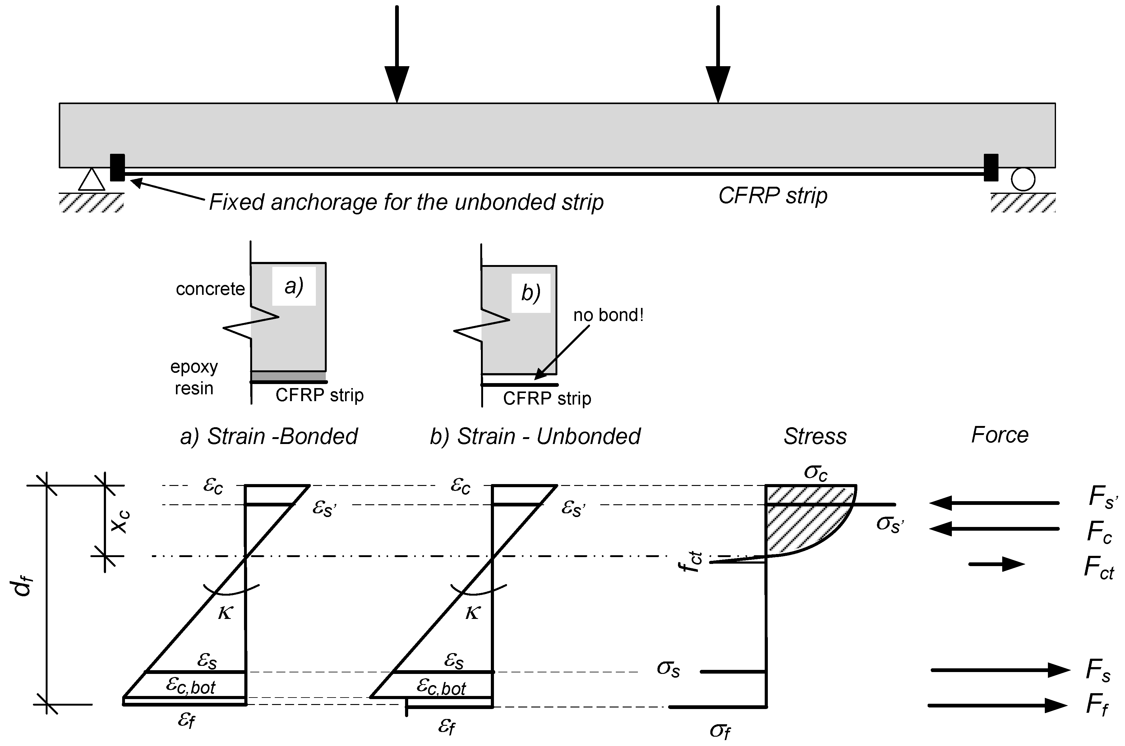
3.3. Constitutive Material Laws

- For initially unstressed EBR, the debonding modes listed in the Swiss design recommendations SIA166 [2] have been used. These include:
- End-anchorage failure (DM1, with: Ff,cr being the CFRP strip force at the last crack, FR being the anchorage resistance):
- Intermediate strip debonding due to interfacial shear stress exceeding (DM2, limit value for the shear strength τlim being a function of the concrete tensile strength):
- Intermediate strip debonding due to CFRP strip strain exceeding (DM3):
- For prestressed CFRP strips, design criteria for the gradient anchorage failure defined in the PhD thesis of Czaderski [31] have been included.
- For prestressed CFRP strips with a mechanical anchorage (Type: S&P Clever Reinforcement Company AG), an upper limit for the CFRP strip strains εf of at maximum 10‰ at the anchorage start have been implemented. This value is based on suggestions given by Suter and Jungo [32].
- For both prestressed configurations with either a gradient or a mechanical anchorage, the intermediate strip debonding as defined in the SIA166 [2] have also been incorporated. The strip strain limitation was based on the additional strip strain Δεf (Verification: Δεf < 8‰). The applicability to prestressed systems has been demonstrated in Harmanci [33].
4. Results and Discussion
4.1. General Comments
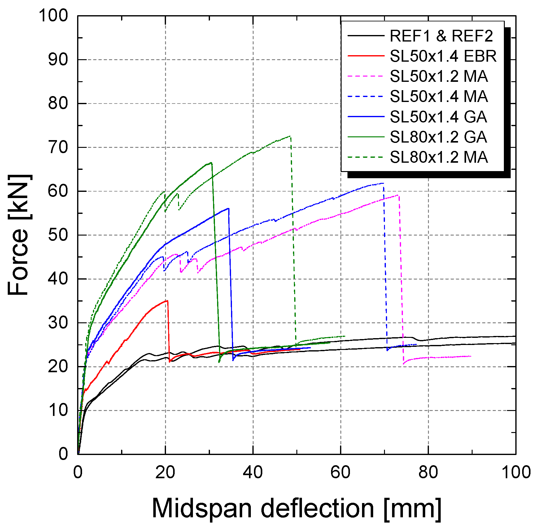
4.2. Failure Modes
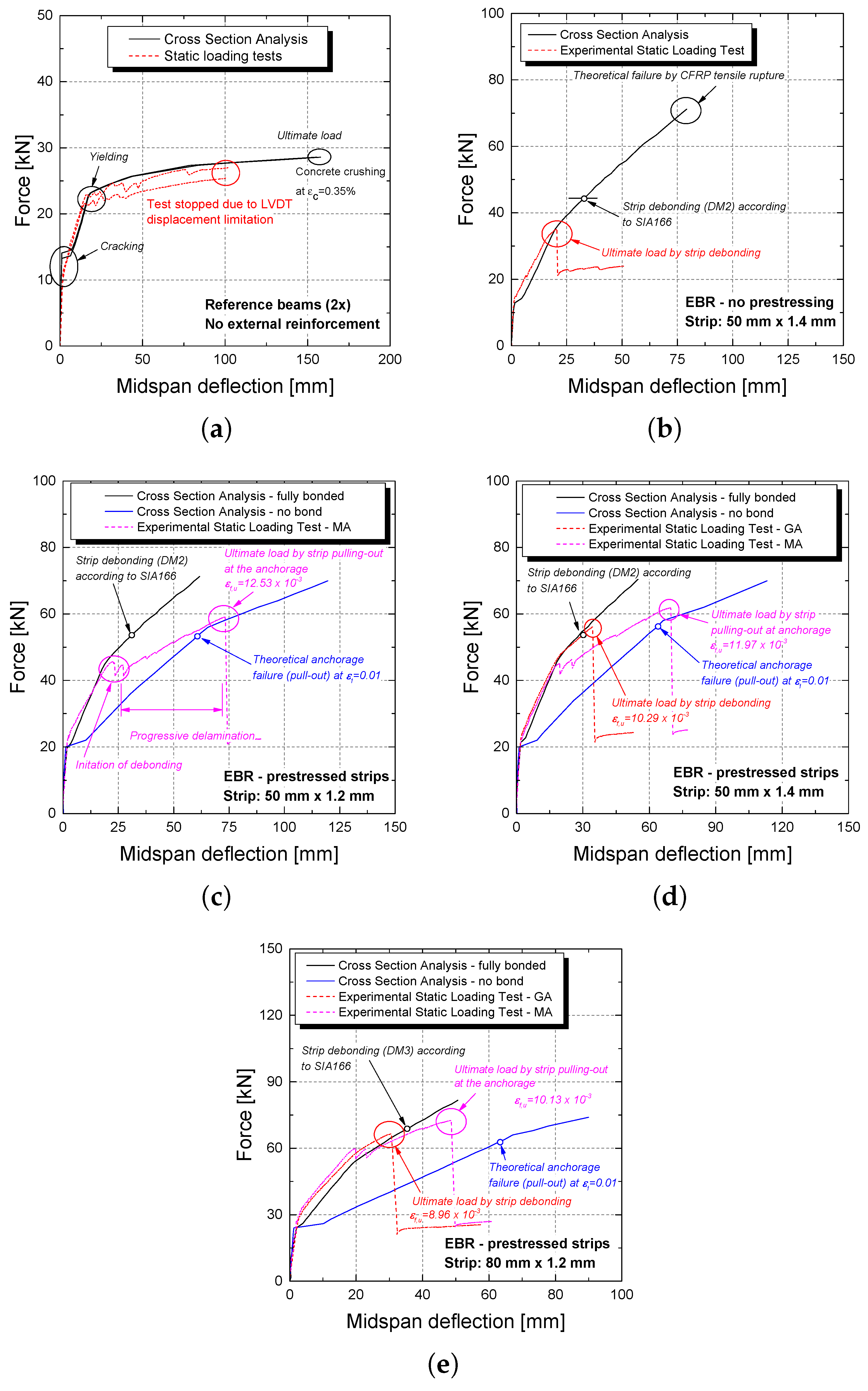
| Plates | δcr (mm) | Fcr (kN) | δy (mm) | Fy (kN) | δu (mm) | Fu (kN) | εf,u (‰) | Failure Mode | μδ = δu/δy | μF = Fu/Fy |
|---|---|---|---|---|---|---|---|---|---|---|
| REF1 | 2.47 | 11.04 | 15.74 | 21.5 | - | - | - | - | ||
| REF2 | 2.49 | 11.12 | 15.96 | 22.9 | - | - | - | - | ||
| SL50x1.4_EBR | 1.64 | 14.73 | 17 | 33.3 | 20.47 | 35.06 | 4.64 | Strip debonding | 1.20 | 1.05 |
| SL50x1.4_GA | 2.25 | 23.84 | 18.86 | 48.35 | 34.39 | 56.02 | 10.29 | Strip debonding | 1.82 | 1.16 |
| SL50x1.4_MA | 2.25 | 22.07 | 17.8 | 44.32 | 69.84 | 61.76 | 11.97 | Strip pulled out of mech. anchorage | 3.92 | 1.39 |
| SL50x1.2_MA | 2.53 | 22.81 | 20.57 | 44.89 | 73.23 | 59.09 | 12.53 | Strip pulled out of mech. anchorage | 3.56 | 1.32 |
| SL80x1.2_GA | 2.88 | 28.56 | 20.31 | 58.31 | 30.61 | 66.21 | 8.96 | Strip debonding | 1.51 | 1.14 |
| SL80x1.2_MA | 2.51 | 28.71 | 18.43 | 58.67 | 48.62 | 72.58 | 10.13 | Strip pulled out of mech. anchorage | 2.64 | 1.24 |
4.3. Prestressed versus Non-Prestressed
4.4. Gradient Anchorage (GA) vs. Mechanical Anchorage (MA)
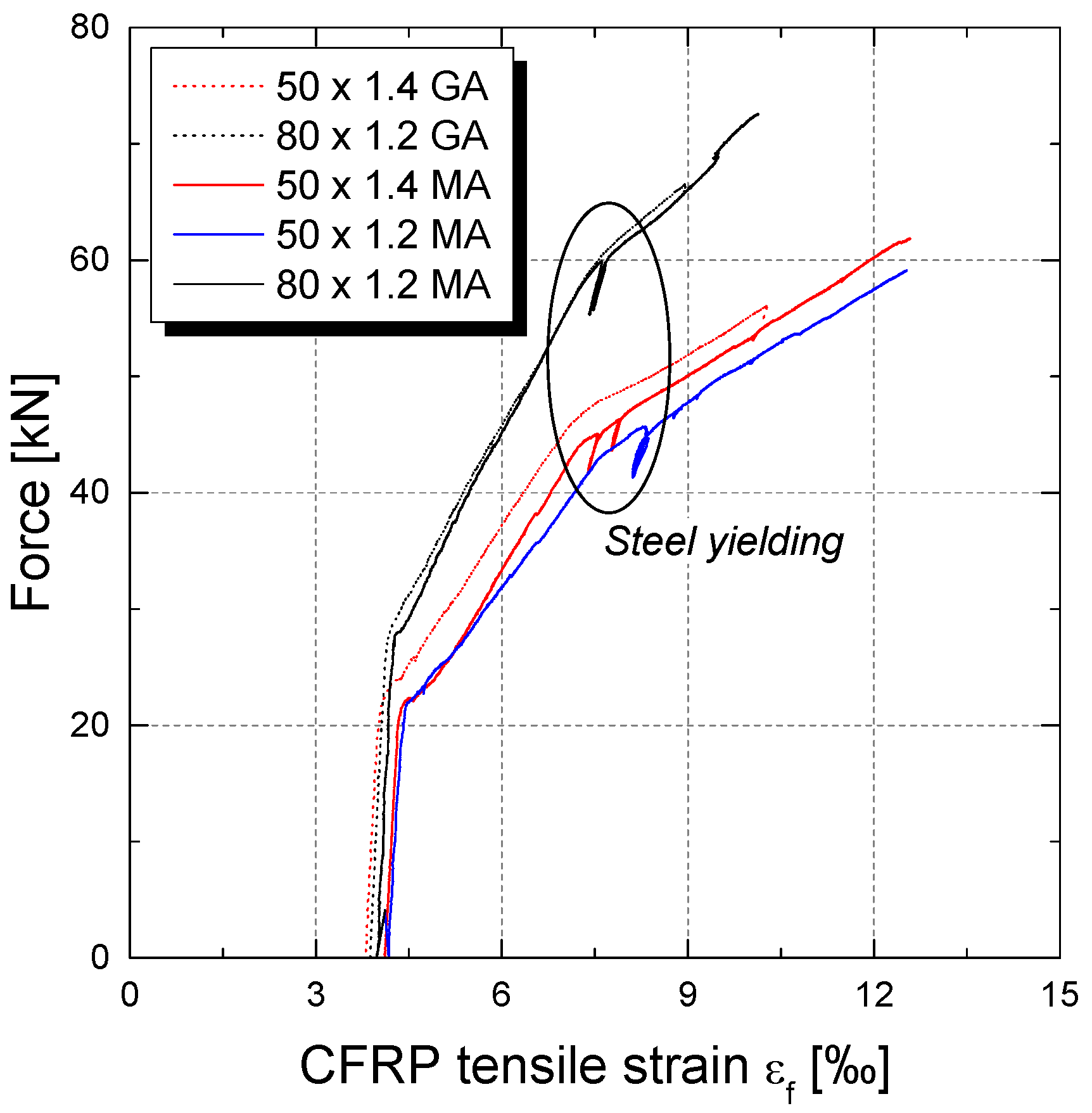
4.5. Influence of FRP Thickness tf and Width bf

4.6. Structural Behavior and Experiments/Simulation Comparison
5. Conclusions and Outlook
- As expected, clearly higher CFRP strains in tension can be reached with an initial prestressing.
- The type of anchorage for prestressed CFRP strips does not affect the behavior at serviceability. Cracking and immediate post-cracking structural behavior is identical for both techniques.
- The application of a gradient anchorage results in a more or less sudden strip debonding. The failure mode is very similar to conventional externally bonded reinforcement without any end-fixations.
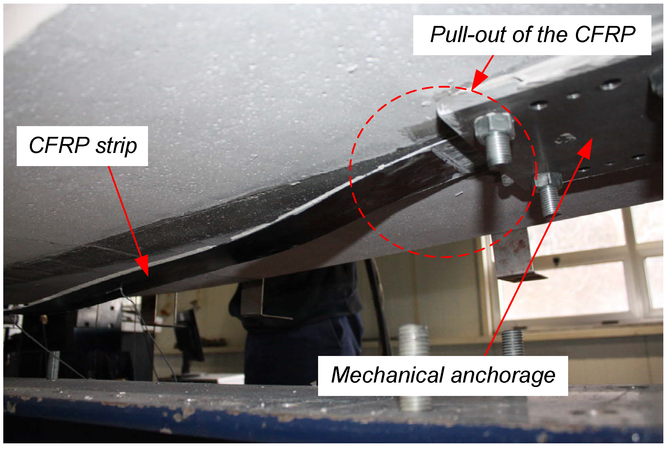
- A mechanical end-anchorage system does also not prevent strip debonding, but allows to transfer the structural behavior from a bonded to an external unbonded-tendon-like behavior. The numerical simulations support this observation. Eventually, failure is obtained by pulling the CFRP strip out of the mechanical anchorage.
- In the present case, the application of a mechanical end-anchorage system implicated a much higher structural ductility when comparing the deflection at failure to the one at yielding. A gradient anchorage was not able to deliver the same amount of deformability.
- The implemented debonding criteria for conventional EBR reinforcements as well as the gradient failure criteria allow to re-calculate the slabs’ behavior in an accurate manner. Future investigations, both experimental and numerical, shoud aim at defining precise pull-out resistances for mechanical anchorages.
Acknowledgments
Author Contributions
Conflicts of Interest
References
- Bakis, C.; Bank, L.; Brown, V.; Cosenza, E.; Davalos, J.; Lesko, J.; Machida, A.; Rizkalla, S.; Triantafillou, T. Fiber-reinforced Polymer Composites for Construction—State-of-the-art Review. J. Compos. Constr. 2002, 6, 73–87. [Google Scholar] [CrossRef]
- Klebebewehrungen (Externally Bonded Reinforcements); SIA 166; Schweizer Ingenieur-und Architektenverein (SIA): Zürich, Switzerland, 2004.
- Strengthening Reinforced Concrete Structures with Externally-Bonded Fibre Reinforced Polymers; The Canadian Network of Centres of Excellence on Intelligent Sensing for Innovative Structures (ISIS Canada): Winnipeg, MB, Canada, 2007.
- Guide for the Design and Construction of Externally Bonded FRP Systems for Strnegthening Concrete Structures; ACI440.2R; American Concrete Institute (ACI): Farmington Hills, MI, USA, 2008.
- Design Handbook for RC Structures Retrofitted with FRP and Metal Plates: Beams and Slabs; Standards Australia: Sydney, Australia, 2008.
- Design Guidance for Strengthening Concrete Structures Using Fibre Composite Materials; Technical Report No. 55 for the Concrete Society: Camberley, UK, 2012.
- Guideline—Strengthening of concrete members with adhesively bonded reinforcement; Deutscher Ausschuss für Stahlbeton (DAfStb): Berlin, Germany, 2012.
- National Research Council (CNR). Istruzioni per la Progettazione, l’Esecuzione ed il Controllo di Interventi di Consolidamento Statico Mediante L’utilizzo di Compositi Fibrorinforzati; CNR-DT 200; CNR: Rome, Italy, 2013. [Google Scholar]
- Czaderski, C.; Motavalli, M. 40-Year-old full-scale concrete bridge girder strengthened with prestressed CFRP plates anchored using gradient method. Compos. Eng. 2007, 38, 878–886. [Google Scholar] [CrossRef]
- Motavalli, M.; Czaderski, C.; Pfyl-Lang, K. Prestressed CFRP for strengthening of reinforced concrete structures: Recent developments at Empa, Switzerland. J. Compos. Constr. 2011, 15, 194–205. [Google Scholar] [CrossRef]
- Wight, R.; Green, M.; Erki, M.A. Prestressed FRP sheets for poststrengthening reinforced concrete beams. J. Compos. Constr. 2001, 5, 214–220. [Google Scholar] [CrossRef]
- Svecova, D.; Razaqpur, A. Flexural behavior of concrete beams reinforced with carbon fiber-reinforced polymer CFRP prestressed prisms. ACI Struct. J. 2000, 97, 731–738. [Google Scholar]
- Kim, Y.; Wight, R.; Green, M. Flexural strengthening of RC beams with prestressed CFRP sheets: Development of nonmetallic anchor systems. J. Compos. Constr. 2008, 12, 35–43. [Google Scholar] [CrossRef]
- Pellegrino, C.; Modena, C. Flexural strengthening of real-scale RC and PRC beams with end-anchored pretensioned FRP laminates. ACI Struct. J. 2009, 106, 319–328. [Google Scholar]
- Michels, J.; Martinelli, E.; Czaderski, C.; Motavalli, M. Prestressed CFRP strips with gradient anchorage for structural concrete retrofitting: Experiments and numerical modeling. Polymers 2014, 6, 114–131. [Google Scholar] [CrossRef]
- El-Hacha, R.; Wight, R.; Green, M. Prestressed fibre-reinforced polymer laminates for strengthening structures. Prog. Struct. Eng. Mater. 2001, 3, 111–121. [Google Scholar] [CrossRef]
- Michels, J.; Sena-Cruz, J.; Czaderski, C.; Motavalli, M. Structural strengthening with prestressed CFRP strips anchored with the gradient method. J. Compos. Constr. 2013, 17, 651–661. [Google Scholar] [CrossRef]
- Laboratório Nacional de Engenharia Civil (LNEC). Concrete—Determination of the Elasticity Young Modulus under Compression; LNEC-E397; LNEC: Lisboa, Portugal, 1993. [Google Scholar]
- Instituto Português da Qualidada (IPQ). Testing Hardened Concrete—Part 3: Compressive Strength of Test Specimens; NP-EN-12390-3; IPQ: Caparica, Portugal, 2011. [Google Scholar]
- Instituto Português da Qualidada (IPQ). Metallic Materials. Tensile Testing. Part 1: Method of Test at Room Temperature; NP-EN-ISO-6892-1; IPQ: Caparica, Portugal, 2012. [Google Scholar]
- International Organization for Standardization (ISO). Plastics—Determination of Tensile Properties—Part 5: Test Conditions for Unidirectional Fibre-Reinforced Plastics; ISO-527-5; ISO: Geneva, Switzerland, 2009. [Google Scholar]
- ISO. Plastics—Determination of Tensile Properties—Part 2: Test Conditions for Moulding and Extrusion Plastics; ISO-527-2; ISO: Geneva, Switzerland, 1993. [Google Scholar]
- Moussa, O.; Vassilopoulos, A.; de Castro, J.; Keller, T. Early-age tensile properties of structural epoxy adhesives subjected to low-temperature curing. Int. J. Adhes. Adhes. 2012, 35, 9–16. [Google Scholar] [CrossRef]
- Granja, J.; Fernandes, P.; Benedetti, A.; Azenha, M.; Sena-Cruz, J. Monitoring the early stiffness development in epoxy adhesives for structural strengthening. J. Adhes. Adhes. 2015, 59, 77–87. [Google Scholar] [CrossRef]
- Czaderski, C.; Martinelli, E.; Michels, J.; Motavalli, M. Effect of curing conditions on strength development in an epoxy resin for structural strengthening. Compos. Eng. 2012, 43, 398–410. [Google Scholar] [CrossRef]
- Michels, J.; Czaderski, C.; El-Hacha, R.; Brönnimann, R.; Motavalli, M. Temporary bond strength of partly cured epoxy adhesive for anchoring prestressed CFRP strips on concrete. Compos. Struct. 2012, 94, 2667–2676. [Google Scholar] [CrossRef]
- Marti, P.; Alvarez, M.; Kaufmann, W.; Sigrist, V. Tension chord model for structural concrete. Struct. Eng. Int. 1998, 8, 287–298. [Google Scholar] [CrossRef]
- Harmanci, Y. Prestressed CFRP for Structural Retrofitting-Experimental and Analytical Investigation. Master’s Thesis, ETH Zürich, Zürich, Switzerland, 2013. [Google Scholar]
- Harmanci, Y.; Michels, J.; Czaderski, C.; Motavalli, M. Calculation technique for externally unbonded CFRP strips in structural concrete retrofitting. J. Eng. Mech. 2015. [Google Scholar] [CrossRef]
- Hognestad, E. A study of combined bending and axial load in reinforced concrete members. Univ. Ill. Eng. Exp. Stn.—Bull. Ser. 1951, 399, 128. [Google Scholar]
- Czaderski, C. Strengthening of Reinforced Concrete Members by Prestressed Externally Bonded Reinforcement with Gradient Method. Ph.D. Thesis, ETH Zürich, Zürich, Switzerland, 2012. [Google Scholar]
- Suter, R.; Jungo, D. Vorgespannte CFK-Lamellen zur Verstärkung von Bauwerken. Beton Stahlbetonbau 2001, 96, 350–358. [Google Scholar] [CrossRef]
- Harmanci, Y. Externally Bonded Reinforcement EBR for Flexural Strengthening of Reinforced Concrete Beams with Rectangular Cross Section; Semester Project, ETH Zürich: Zürich, Switzerland, 2011. [Google Scholar]
© 2015 by the authors; licensee MDPI, Basel, Switzerland. This article is an open access article distributed under the terms and conditions of the Creative Commons by Attribution (CC-BY) license (http://creativecommons.org/licenses/by/4.0/).
Share and Cite
Sena-Cruz, J.; Michels, J.; Harmanci, Y.E.; Correia, L. Flexural Strengthening of RC Slabs with Prestressed CFRP Strips Using Different Anchorage Systems. Polymers 2015, 7, 2100-2118. https://doi.org/10.3390/polym7101502
Sena-Cruz J, Michels J, Harmanci YE, Correia L. Flexural Strengthening of RC Slabs with Prestressed CFRP Strips Using Different Anchorage Systems. Polymers. 2015; 7(10):2100-2118. https://doi.org/10.3390/polym7101502
Chicago/Turabian StyleSena-Cruz, José, Julien Michels, Yunus Emre Harmanci, and Luís Correia. 2015. "Flexural Strengthening of RC Slabs with Prestressed CFRP Strips Using Different Anchorage Systems" Polymers 7, no. 10: 2100-2118. https://doi.org/10.3390/polym7101502
APA StyleSena-Cruz, J., Michels, J., Harmanci, Y. E., & Correia, L. (2015). Flexural Strengthening of RC Slabs with Prestressed CFRP Strips Using Different Anchorage Systems. Polymers, 7(10), 2100-2118. https://doi.org/10.3390/polym7101502