Article

Embedding of Hollow Polymer Microspheres with Hydrophilic Shell in Nafion Matrix as Proton and Water Micro-Reservoir

1
Department of Chemical & Biomolecular Engineering, National University of Singapore, 10 Kent Ridge Crescent, 119260, Singapore
2
Institute of Materials Research and Engineering, 3 Research Link, 117602, Singapore
*
Author to whom correspondence should be addressed.
Polymers 2012, 4(3), 1499-1516; https://doi.org/10.3390/polym4031499
Submission received: 19 June 2012 / Revised: 1 August 2012 / Accepted: 10 August 2012 / Published: 20 August 2012
(This article belongs to the Special Issue Polymers for Fuel Cells & Solar Energy)

Abstract

:
Assimilating hydrophilic hollow polymer spheres (HPS) into Nafion matrix by a loading of 0.5 wt % led to a restructured hydrophilic channel, composed of the pendant sulfonic acid groups (–SO3H) and the imbedded hydrophilic hollow spheres. The tiny hydrophilic hollow chamber was critical to retaining moisture and facilitating proton transfer in the composite membranes. To obtain such a tiny cavity structure, the synthesis included selective generation of a hydrophilic polymer shell on silica microsphere template and the subsequent removal of the template by etching. The hydrophilic HPS (100–200 nm) possessed two different spherical shells, the styrenic network with pendant sulfonic acid groups and with methacrylic acid groups, respectively. By behaving as microreservoirs of water, the hydrophilic HPS promoted the Grotthus mechanism and, hence, enhanced proton transport efficiency through the inter-sphere path. In addition, the HPS with the –SO3H borne shell played a more effective role than those with the –CO2H borne shell in augmenting proton transport, in particular under low humidity or at medium temperatures. Single H2-PEMFC test at 70 °C using dry H2/O2 further verified the impactful role of hydrophilic HPS in sustaining higher proton flux as compared to pristine Nafion membrane.

1. Introduction

Proton exchange membrane fuel cell (PEMFC) has attracted much attention because of its high power density and efficiency with nil green-house gas emission [1,2]. In pursuit of fast electrode kinetics, operating PEMFC at medium temperatures (70~100 °C) has been attempted [3]. Hence, equipping Nafion membrane with a strong moisture-retention capability becomes necessary for maintaining the required proton conductivity through this temperature range. Incorporation of inorganic particles (e.g., silica, zeolites) into Nafion membrane matrix to enhance hygroscopy of membrane is representative of earlier efforts [4,5,6,7,8,9,10]. In the resulting composite membrane, hydrogen bonding between the surface hydroxyl group of inorganic filler and the pendant sulfonic acid group (–SO3H) of Nafion assists the dispersion of filler particles in the host matrix [11,12]. Grafting hydrophilic oligomeric chains to inorganic particles [3,4,5,6,7,8,9,10,11,12,13,14,15] has furthered the preparation technique of Nafion nanocomposite membranes. With the aim of achieving the forestated goal, use of hydrophilic hollow polymer spheres (HPS) as filler is apparently more attractive [16,17,18,19,20,21] because this particulate structure possesses larger interior space for storing water and the porous hydrophilic polymeric shell prevents quick evaporation of water while the membrane is subjected to dehydration [22,23]. It has also been considered that the Grotthuss mechanism became dominant in the presence of hydrophilic HPS in a PEM matrix [24] because the matrix water strongly associates with pendant hydrophilic functional groups and is therefore immobile. Despite recognition of the role of hydrophilic HPS in promoting proton conductivity in PEMs, it is essential to examine how the moisture-retention property of hydrophilic HPS in a PEM affects the fuel cell performance. Furthermore, it is imperative to understand how explicitly a particular type of HPS filler in a PEM, for instance Nafion, alters the matrix structure and then properties of the composite membrane, including water uptake, proton conductivity under low humidity condition, and ion-exchange capability. Hence, this work explored the attainable maximum power density of single fuel cell loaded with a HPS-Nafion composite membrane and its structural origins. HPS (100–200 nm) were synthesized through a three-step procedure as illustrated in Scheme 1, which is similar to the literature method [25].
Scheme 1. Schematic illustration for the preparation of s-HPS (hydrophilic hollow polymer spheres), where 3: DVB/Styrene, 4: H2SO4, and 5: HF.
Polymers 04 01499 g010
Two types of hydrophilic HPS, with poly (sulfonated styrene-divinylbenzene) shell (s-HPS) and poly (methacrylic acid-divinylbenzene) shell (c-HPS), respectively, were obtained from this preparation. Variations of the water-related membrane properties due to the presence of these two types of HPS in Nafion matrix by 0.5 wt % loading were studied. The results revealed that the reduction in proton conductivity, caused by removing moisture from the HPS-Nafion composite membranes in dry or hot surroundings, could be noticeably held back. Furthermore, the obvious superiority of the composite membranes over the control samples, the cast and commercial Nafion membranes is reflected in the single fuel cell evaluation. The present work validates the role of microreservoirs of water and proton in a PEM matrix, which not only helps to retain matrix water but also promote convection of protons.

2. Experimental Section

2.1. Materials

Tetraethyl orthosilicate (TEOS, 98%), 3-(trimethoxysilyl) propylmethacrylate (MPS, 98%), styrene (St) (>99%, Aldrich), divinylbenzene (DVB) (80%, Aldrich), 2,2'-azobisisobutyronitrile (AIBN) (98%, Aldrich), methacrylic acid (MAA) (>98%, Aldrich), hydrofluoric acid (HF) (48% in water, Aldrich), doubly distilled water (DDW), ammonia (25% in water, Aldrich) and analytical grade acetonitrile and ethanol were used for the experimental processes.

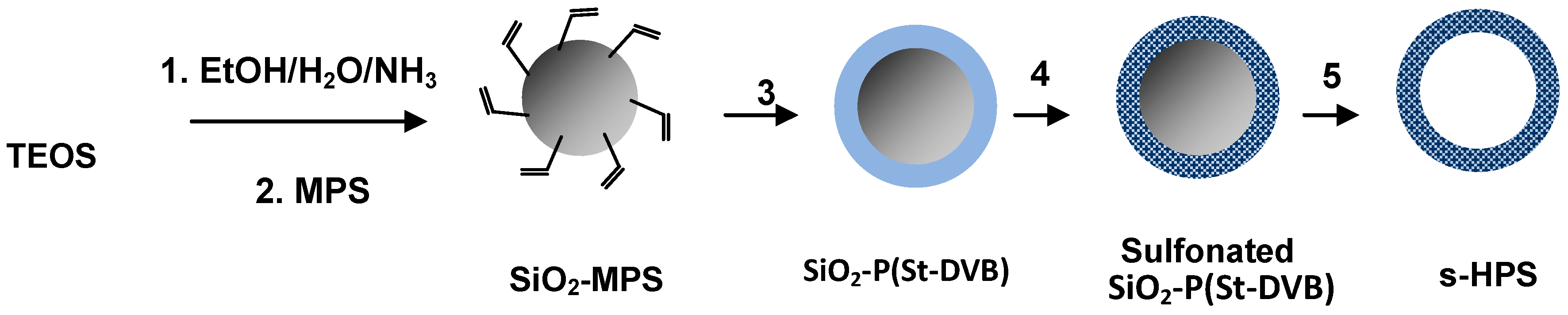
2.2. Synthesis of SiO2-MPS Nanoparticles

MPS modified silica templates were prepared according to the Stöber method [26,27]. About 4.5 mL of TEOS was added to a mixture of 75 mL ethanol, 7.5 mL DDW, and 1.5 mL ammonia. The mixture was vigorously stirred at room temperature for 24 h. A total of 1 mL MPS was then injected into the silica sol dispersion and the dispersion was stirred at room temperature for another 24 h. After the reaction, the resultant MPS modified silica particles SiO2-MPS were purified by centrifuge.

2.3. Synthesis of SiO2/Polymer Core-Shell Nanoparticles

About 0.2 g SiO2-MPS powder was dispersed into 80 mL of acetonitrile under ultrasonication in a 100 mL flask, equipped with a fractionation column, a condenser, and a receiver. A mixture of St (1.15 mL, 0.01 mol), DVB (0.267 mL, 0.0015 mol, 15 mol% relative to styrene), and 2,2'-azobisisobutyronitrile (AIBN, 0.02 g) was then added into the flask. The polymerization then proceeded under reflux and removing of solvent by gradual distillation. Through this distillation process, the P(St-DVB) network formed in the solution phase underwent effective grafting to the MPS surface anchors, leading to a polymer shell on each SiO2 microsphere. The reflux lasted 1.5 h and 40 mL acetonitrile was distilled off. The resultant SiO2-P(St-DVB) core-shell microspheres were purified using soxhlet extraction procedure in which the remaining monomers and oligomers were removed by a binary solvent of acetonitrile and ethanol. The resulting SiO2-P(St-DVB) powder was vacuum dried at 50 °C. The particles were then sulfonated in a concentrated sulfuric acid at 50 °C for 3 h and the mixture was poured into a cold ethanol to allow sedimentation of pale yellow particles. After centrifuging and washing with ethanol, the collected powder was vacuum dried. Similarly, the preparation of SiO2/P(MAA-DVB) was prepared by the distillation polymerization except sulfonation. Hence two different types of hydrophilic SiO2/polymer core-shell particles were synthesized.

2.4. Synthesis of Hollow Polymer Micropheres (HPS)

The SiO2/polymer core-shell microspheres were treated in 8% HF for 48 h by gentle agitation in a plastic flask. The unused HF and reaction product (SiF4) in liquid phase were separated from the hollow microspheres by centrifuging and the microspheres were washed in ethanol and water for several cycles. The hollow polymer spheres prepared are labeled by s-HPS and c-HPS, respectively, with the former bearing –SO3H pendant groups while the later one –CO2H pendant groups. The equivalent weights of s-HPS (5.7 mmol SO3H/g) and c-HPS (4.8 mmol CO2H/g) were determined by titration. In a typical run, 0.01g sample was gently stirred in 20 mL 0.01M NaOH for overnight. The mixture was centrifuged and the clear decant was titrated by 0.01M HCl. In addition, the sample of hollow spheres with the pristine P(St-DVB) was prepared as control.

2.5. Fabrication of the Composite Membranes

As a typical procedure, Nafion solution (5 wt % in a mixture of low aliphatic alcohols/H2O (20%), EW 1100) was mixed with HPS (0.5 wt % on the basis of dry Nafion resin). The suspension was ultrasonicated until a homogeneous sol was obtained. The sol was casted onto a petri dish and dried at 80 °C for 12 h. The membrane obtained was soaked in 1 M H2SO4 for at least 24 h before use. The thickness of membranes was fixed at about 50 μm. Three composite membranes obtained are named by N/s-HPS, N/c-HPS and N/n-HPS. As defined above, the first two denote the composite membranes containing s-HPS and c-HPS in Nafion matrix respectively, while the last one denotes the composite membrane containing the HPS that has neutral or hydrophobic P(St-DVB) shell, which was prepared as the control sample.

2.6. Characterizations

2.6.1. Structural Characterizations

The functional group types of the three HPS samples were confirmed on a Fourier transform infrared spectrophotometer (Bio-Rad FTS 135). The field emission scanning electron microscopy (FESEM) of the cross-section of membrane was recorded on a JEOL JSM-6700 scanning electron microscope. The transmission electron microscopy (TEM) images of HPS were obtained on a JEOL JEM-2010 transmission electron microscope.

2.6.2. Determination of Water Uptake and Ionic Exchange Capacity (IEC)

After vacuum drying at 80 °C for 8 h, the membrane obtained with a dry weight (Wdry) was immersed in water at room temperature for 24 h to give a wet weight (Wwet). The water uptake (WwetWdry)/Wdry × 100% could then be determined. The IEC was measured by soaking a piece of dry membrane in a sodium chloride aqueous solution (0.05 M) at room temperature for 24 h to allow equilibrium of ion-exchange between H+ and Na+ to be achieved. After that, the solution was titrated to pH 7.0 using a standard 0.05 M sodium hydroxide aqueous solution and the end-point of titration was indicated by a pH meter (HORIBA). Each data point of water-uptake and IEC measurements reported was generated from averaging the three repeating measurement results.

2.6.3. Thermal Analysis of the Cast Membranes

The states of water trapped in a membrane were determined by differential Scanning Calorimetry (DSC) (Mettler Toledo DSC 822e) in the range from −100 to 100 °C by a heating rate of 5 °C/min. The fraction of freezable and non-freezable water can be evaluated by the following equations [28,29,30].
Polymers 04 01499 i001
Where ∆Hmelt is the specific fusion heat of the water in a membrane; ∆Hf, ice is the fusion heat of pure ice (334 J/g).

2.6.4. Electrochemical Properties of the Composite Membranes

The proton conductivity of a membrane was measured using the normal four-probe method at different temperatures or under various RH% conditions [31,32]. The sample cell was composed of two Teflon plates in rectangular shape, on one of which four parallel metal probes were fixed with the two outer ones (stain less steel ribbon) as current-carrying electrodes and the two inner ones (copper wires) as potential-sensing electrodes. In a typical run, a fully hydrated membrane sample was brought in contact with the four electrodes and a window designed on both Teflon plates to allow for rapid equilibrating of the sample with that of the measurement environment. The sample was then immediately placed in a closed chamber with a designated RH% at a selected temperature and the corresponding σ value was recorded down. The electrical resistance of the sample was taken using an electrochemical analyzer (Autolab Instrument) at galvanostatic mode with the AC current amplitude of 0.1 mA and the frequency scanning range from 0.1 Hz to 1 MHz. To evaluate the performance of a membrane in fuel cell, a single cell was operated using pure H2 and O2(1 bar, 50 cm3 min−1) without humidifying hydrogen. The membrane-electrolyte assembly was made by sandwiching the 1M H2SO4-soaked membrane between an anode and a cathode sheet. The anode and cathode sheet were a carbon paper (SGL, Germany) with carbon-supported 20 wt % Pt catalyst layer supplied by E-TEK, Natick, MA. The catalyst loadings at the anode and cathode were 2 mg/cm2, respectively. The effective electrode area was 2 cm2. The electrode polarization curve was obtained by setting a series of cell current and recording the corresponding current voltages.

3. Results and Discussion

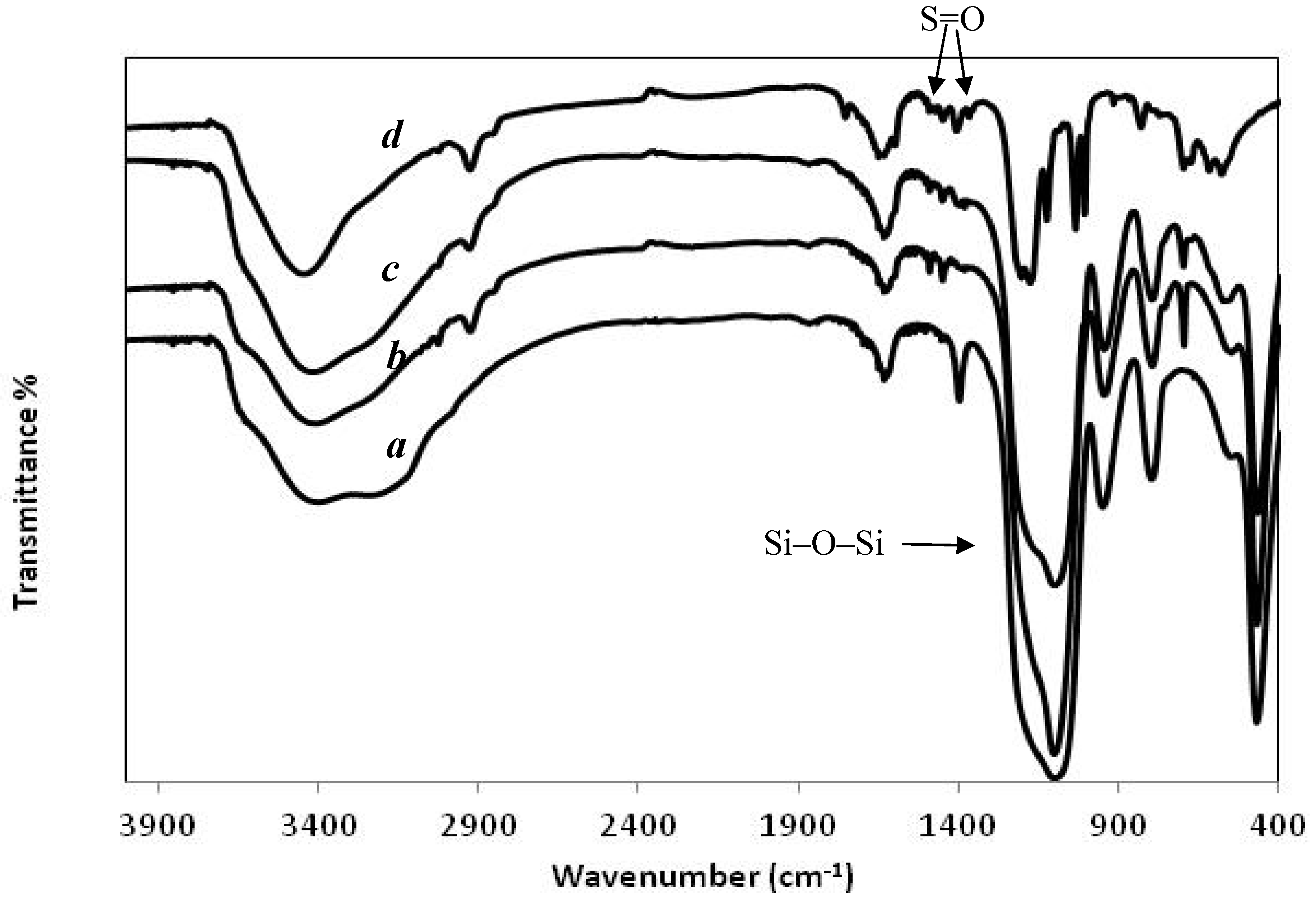
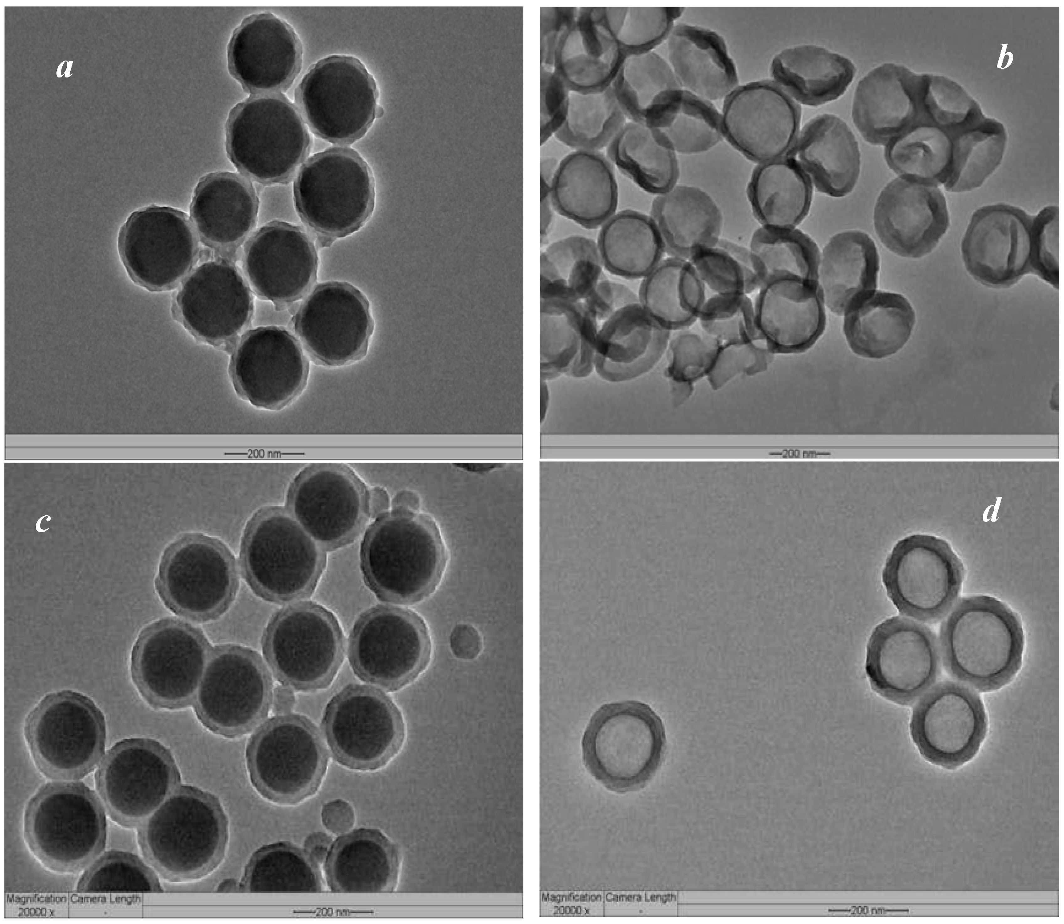
3.1. Characteristics of the HPS

The synthesis of submicron s-HPS employed the bottom-up strategy as depicted in Scheme 1 and the respective FTIR spectrum was shown in Figure 1. Initially SiO2-MPS seed particles with diameters of 100–150 nm were synthesized using the Stöber process [26,27]. The FTIR absorption spectrum of the SiO2-MPS particles shows a peak at 1630 cm−1 (Figure 1a), which corresponds to the double bond (vinyl groups) stretching of the MPS units attached to the SiO2 microspheres. This peak shows a shoulder at about 1730 cm−1 representing the carbonyl group. Vinyl groups on the surface of SiO2-MPS microspheres then served as anchor to the radical chains produced in the solution upon polymerization, and the accompanying distillation drove the interfacial grafting to generate the SiO2-P(St-DVB) core-shell microspheres. The spectrum (Figure 1b) proves realization of this structure according to benzene ring stretching at 1500 cm−1, aromatic C–H stretching at 3010 cm−1 and the main chain C–H stretching at 2900 cm−1. The subsequent sulfonation introduced –SO3H groups to benzene rings in the P(St-DVB) shell. The characteristic double S=O stretching peaks at about 1041 and 1180 cm−1 could be observed only after silica core was removed since the broad –Si–O–Si– symmetric stretching peak appears at 1000~1200 cm−1 (Figure 1b).
Figure 1. (Fourier Transform Infrared Spectroscopy) FTIR spectra: (a) 3-(trimethoxysilyl) propylmethacrylate (MPS) modified SiO2 seeds; (b) SiO2-P(styrene-divinylbenzene)(SiO2-P(St-DVB)) core-shell spheres; (c) the sulfonated SiO2-P(St-DVB) spheres; and (d) s-HPS.
Polymers 04 01499 g001
Figure 2 shows the TEM image of the core-shell structures of the SiO2/P(St-DVB) and SO2/P(MAA-DVB) spheres. The resultant core-shell microspheres of both types had a 20–30 nm thick shell. Hollow polymer spherical structure with two types of functional groups, –SO3H (s-HPS) and –CO2H (c-HPS), were securely retained after the silica core was removed. It is noteworthy that the P(St-DVB) must be sulfonated in the presence of SiO2 core in order to etch the SiO2 core more readily and to avoid splintering of the P(St-DVB) shell while it is sulfonated. The hollow structures of the s-HPS and c-HPS spheres exhibited well-defined capsular structure and an integrity shell. Also, the sufficiently high DVB crosslinking extent assured a free-standing shell and prevented severe agglomeration among HPS of both types.
Figure 2. TEM images: (a) SiO2-P(St-DVB); (b) s-HPS; (c) SiO2-P(methacrylic acid- divinylbenzene) (SiO2-P(MAA-DVB)); and (d) c-HPS sphere.
Polymers 04 01499 g002

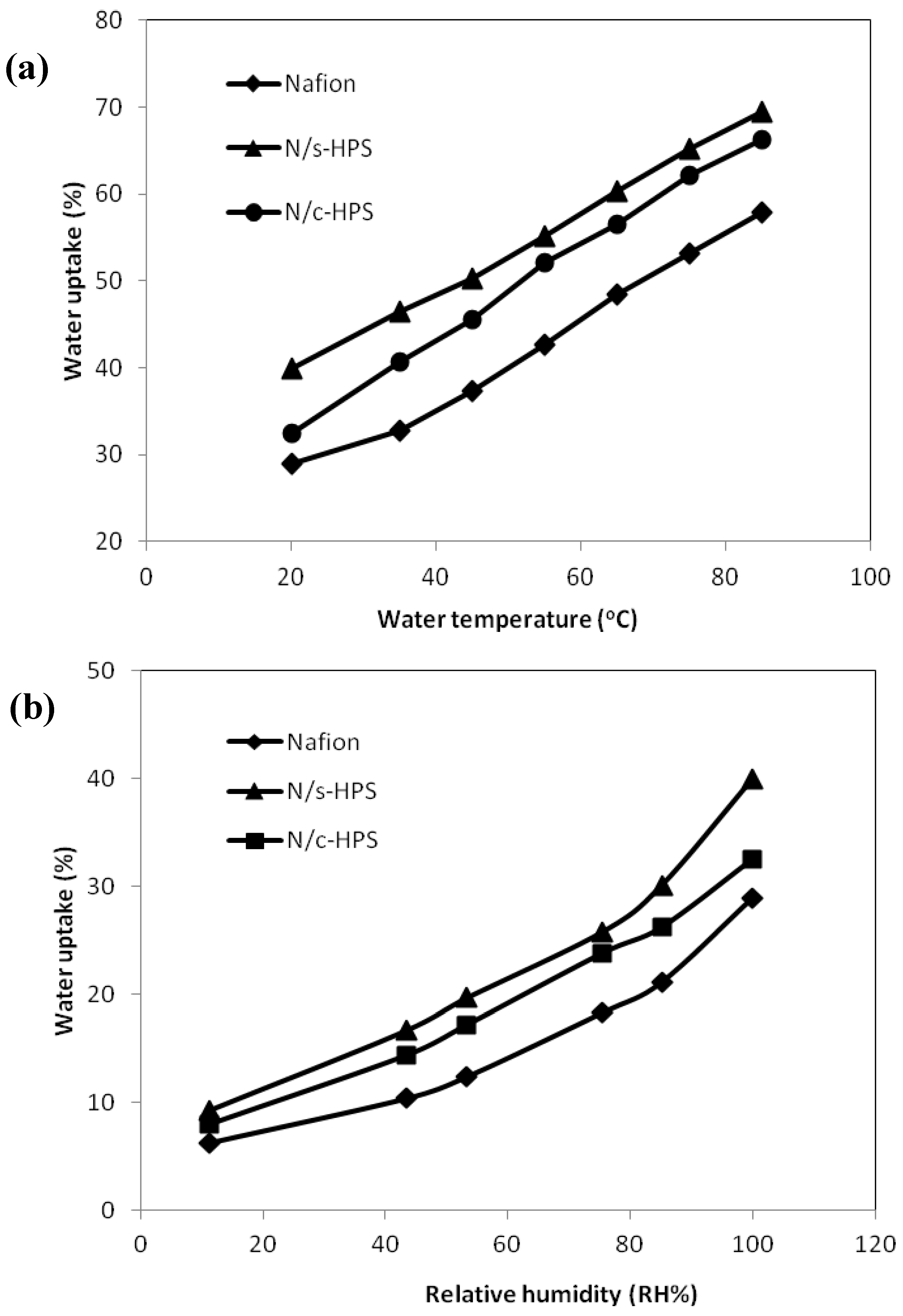
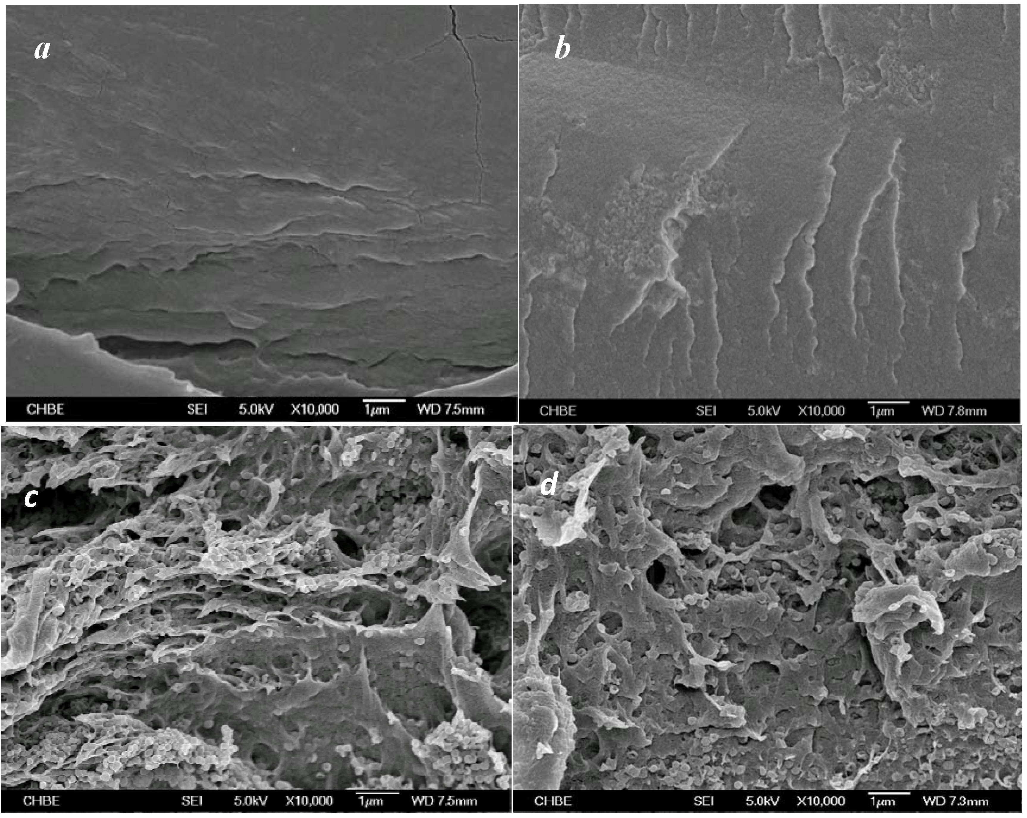
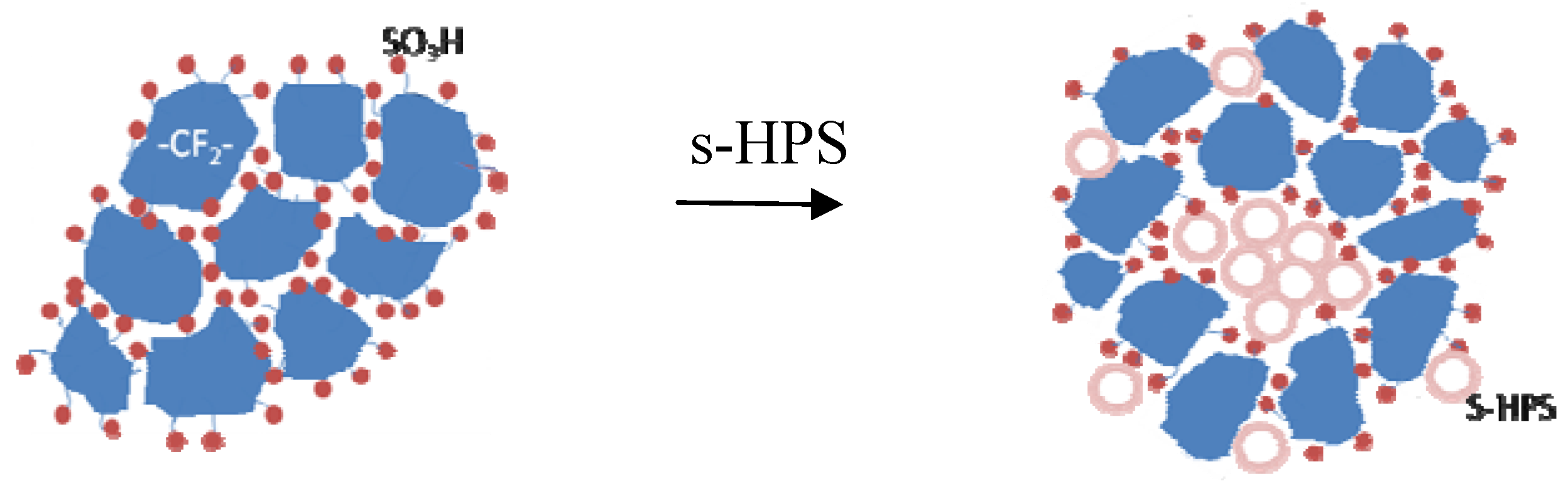
3.2. Broadening Hydrophilic Channel of Nafion by Hydrophilic HPS

The cryofractured cross-sections of the four membranes of interest exhibited a clear transition from a dense and homogeneous matrix of the pristine Nafion membrane to a micro-rupturing matrix of the composite membranes, i.e., N/s-HPS and N/c-HPS. This change in morphology is typically due to interaction between Nafion matrix and the filler used. The composite membrane N/n-HPS, containing neutral HPS, nevertheless still held a rather homogeneous matrix, analogous to its pristine counterpart (Figure 3a). Assimilating either s-HPS or c-HPS into Nafion matrix was to trigger hydrophilic interaction between –SO3H groups of Nafion molecules with s-HPS or with c-HPS [33]. Compared to the microstructure of the pristine Nafion (Figure 4), consisting of perfluoro-polymer domains and a hydrophilic and continuous boundary phase, hence the hydrophilic HPS associated with the boundary composed of pendant –SO3H groups to form a particle-domain packing morphology since both have roughly comparable submicron particle sizes (Scheme 2). As a result, the association of the Nafion domains became insignificant or was weakened due to spatially distancing effect. After drying, such composite membrane is mechanically weaker than the denser pristine Nafion membrane matrix. Hence, numerous micro-ruptures could be observed across the cross-section (Figure 3c,d). Owing to considerably low specific density, 0.5 wt % loading of either c-HPS or s-HPS would have taken up a large volume fraction of the hydrophilic phase of Nafion. However, the smaller volume fraction of hydrophilic phase, relative to the hydrophobic perfluoropolymer phase, in Nafion could not separate the filler particles extensively and thereby the structure of composite can be illustrated by Scheme 2, which was actually verified by many loosely bound hydrophilic HPS and the broadened gap between the Nafion domains in Figure 3c,d.
Figure 3. (a) Field emission scanning electron microscopy (FESEM) images of the cross-section of Nafion; (b) N/n-HPS; (c) N/s-HPS; and (d) N/c-HPS composite membranes. A 0.5% loading of HPS filler exists in each composite membrane.
Polymers 04 01499 g003
Figure 4. The cross-sectional FESEM of the cast Nafion membrane.
Polymers 04 01499 g004
Scheme 2. The formation of the Nafion/hollow sphere composite membrane structure.
Polymers 04 01499 g011
These hydrophilic HPS aggregates functioned as strong moisture reservoir with prominent effect on proton transport, which will be elaborated in the following section. Despite the positive effect of hydrophilic HPS, a loading exceeding 0.5 wt % would further weaken the cohesive strength of membrane and hence be irrelevant. On the contrary, being hydrophobic in nature, n-HPS particles were likely to be entangled by perfluoro-chains upon drying. As the hydrophobic perfluorocarbon chains take up the major volume fraction and this hydrophobic combination does not or only slightly perturb the ionic clustering of –SO3H throughout the membrane, a dense morphology could still remain after being cryofractured. In summary, the hydrophilic HPS filler acted to broaden proton conducting channel in the composite Nafion membrane.

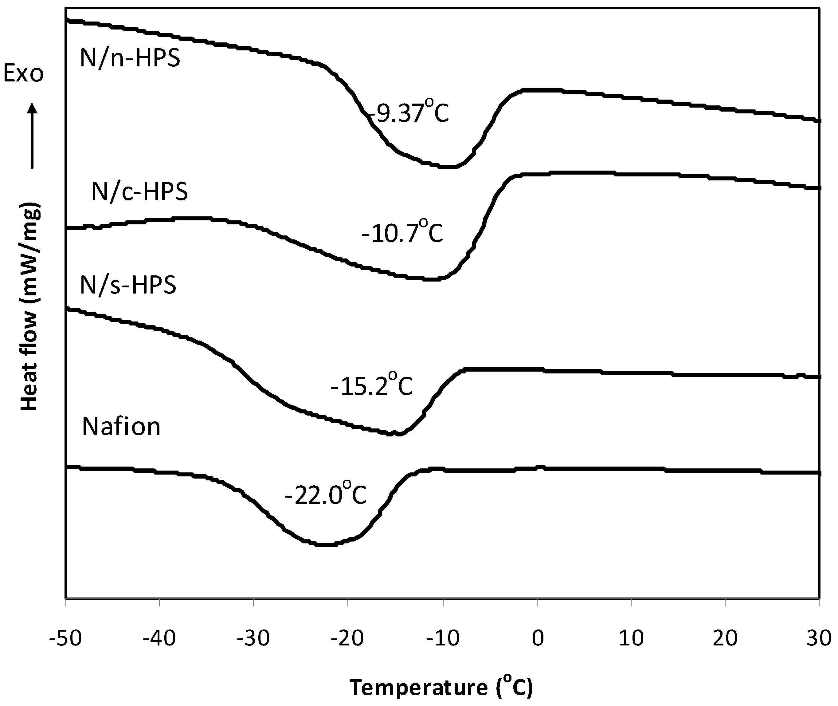
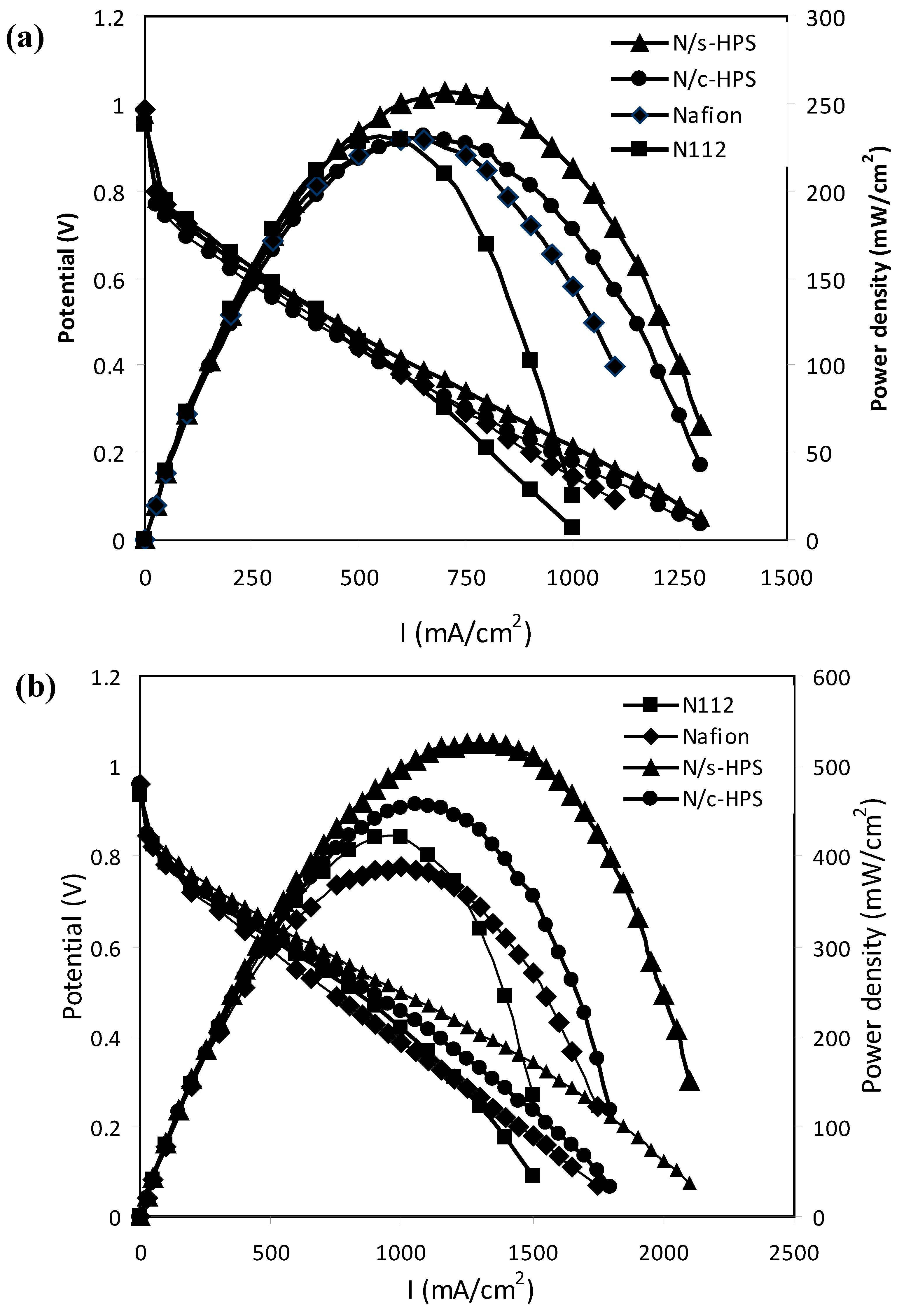
3.3. Effects of Water Micro-Reservoir in the Composite Membranes

It is believed that proton transport occurs in hydrophilic channel consisting of acidic groups (typically –SO3H) and proton-water clusters (such as H3O+, H5O2+, and H9O4+) [34,35,36]. Therefore, besides the concentration of sulfonic acid groups, both physical states and content of the water entrapped in hydrophilic channel are influential to the proton transportation. As proposed above, the assimilation of hydrophilic HPS into Nafion was to enhance water uptake. The temperature effect on water uptake at 100% RH showed the sequence as expected (Figure 5a) where N/s-HPS revealed the largest water-absorption capacity of the three membranes under investigation. Furthermore, their water absorption capability was examined by equilibrating the membranes with different RH% at 20 °C (Figure 5b). The composite membranes revealed stronger moisture capture capability than the pristine cast membrane. Fundamentally, this implies the existence of a denser distribution of hydrophilic sites in the composite membranes. Furthermore, the condensed states of water entrapped in a membrane can be described by “free water” freezing at 0 °C, “freezable bound water” or “freezable water” freezing below 0 °C, and “non freezable bound water” or “non freezable water” due to absence of hydrogen bonding among water molecules, and hence, no phase transition can be detected.
Both free water and freezable water can be identified by the low temperature DSC profiles [37,38] as shown in Figure 6. The four membranes displayed only freezable water existing below 0 °C. Assuming that the specific fusion heat of freezable water would remain approximately the same as that of free water (4.18 cal/g) regardless of the shift of freezing point, the amount of this type of water could be calculated (Table 1). Subsequently, the non-freezable water would be the difference between water uptake and the amount of the freezable water. In contrast to the freezing point of freezable water in the Nafion membrane, which is identical to the reported value [38,39], the freezable water in the three composite membranes showed higher freezing point as expected due to the lodging of water inside the chamber of HPS. Unlike some hydrophilic polymer matrices, such as poly(vinyl alcohol) [40] and sulfonated polystyrene [41], these three composite membranes contain no free water. This observation can be attributed to the substantially small sizes of dispersed water droplets and a high percentage of water molecules associating with the pendant –SO3H groups. Hence, the bulk properties of the water droplets significantly faded. By this interfacial effect, the stronger the interfacial interactions between water droplets and hydrophilic groups, the lower the freezing point. Indeed the water freezing points of the composite membranes showed the order: N/s-HPS < N/c-HPS < N/n-HPS, which is determined by the hydrophilic affinity of HPS, i.e., the stronger affinity led to stronger interfacial interactions following the order of s-HPS > c-HPS >> n-HPS in terms of hydrophilicity. This order also reflects the same trend of freezable water% described in Table 1.
Figure 5. The water uptake of the various membranes: (a) impact of temperature under 100% RH; and (b) impact of % relative humidity (RH)relation at 20 °C.
Polymers 04 01499 g005
Figure 6. Differential Scanning Calorimetry (DSC) investigation on the condensed state of water in various membranes.
Polymers 04 01499 g006
Table 1. Hydrophilic properties of Nafion and the composite membranes.
MembraneIEC (mmol/g)Water uptake (%, 20 °C)Melting peak (°C)Freezable water (%)Non Freezable water (%)
Nafion0.75 ± 0.0128.9 ± 2.3−22.013.815.1
N/n-HPS0.75 ± 0.0330.1 ± 2.2−9.3718.911.2
N/c-HPS0.82 ± 0.0232.5 ± 2.1−10.720.213.3
N/s-HPS0.88 ± 0.0640.0 ± 3.3−15.226.713.3
Of the three composite membranes, the N/n-HPS membrane contained hydrophobic n-HPS particles that associated with perfluorochains as ascribed above. The analysis of water state further suggests that this association reduce the packing density of perfluoro chains because of the occurrence of the interface between perfluorochain and P(St-DVB). Such perturbation occurring in the hydrophobic domains might also affect the clustering of –SO3H groups in the hydrophilic channels to a small extent. This is supported by the increase in freezable water content and the reduction in non-freezable water content in the N/n-HPS relative to the pristine Nafion membrane.
The measured IEC values (Table 1) unveil not only the equilibrium accessibility to the pendant acid groups but also structural response in connection with the above assignment on hydrophilic channel. Both Nafion and N/n-HPS show the same IEC, implying no blockading action imposed by the n-HPS particles to the hydrophilic channels. Moreover, the composite membranes, N/c-HPS and N/s-HPS, showed IEC values of 0.82 and 0.88 mmol/g, respectively. The calculated value of IEC of N/s-HPS can be made using the measured IEC of Nafion membrane (0.75 mmol/g) and the measured equivalent mass of s-HPS (5.7 mmol/g) by the formula: 0.5% × 5.7 mmol/g + 99.5% × 0.75 mmol/g = 0.775 mmol/g. Obviously, this calculated value is well below the experimental IEC of N/s-HPS. This difference of about 13.5% validates the role of s-HPS particles in broadening hydrophilic channel, which opened accessibility of those dead ends in the pristine Nafion matrix. A similar discrepancy also existed in N/c-HPS. In addition, the difference in IEC between N/s-HPS and N/c-HPS is 0.06 mmol/g, a far greater discrepancy than that between s-HPS and c-HPS (i.e., 0.0045 mmol/g). As found previously, the IEC value is largely affected by a strong acid rather than a weak acid [42].

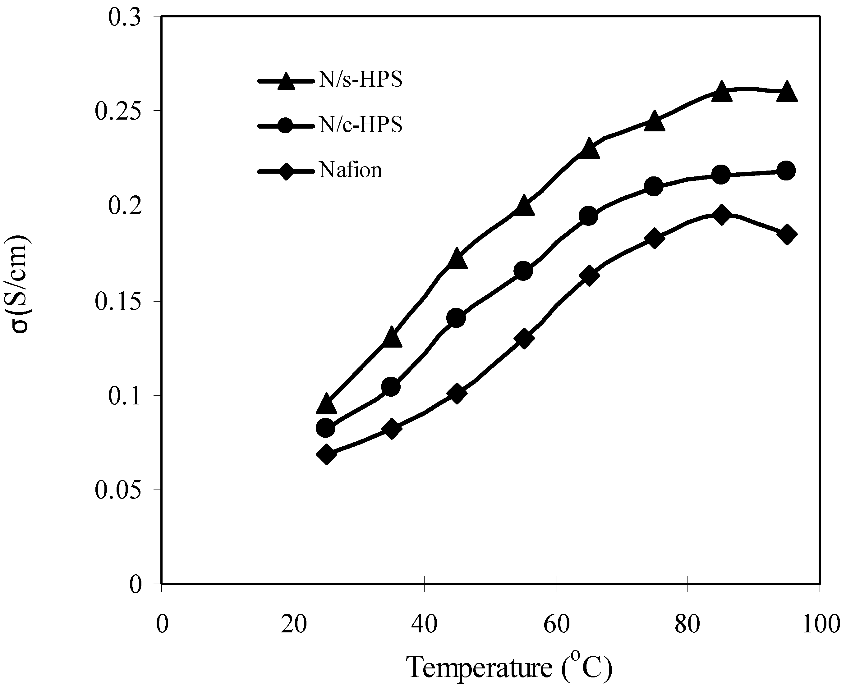
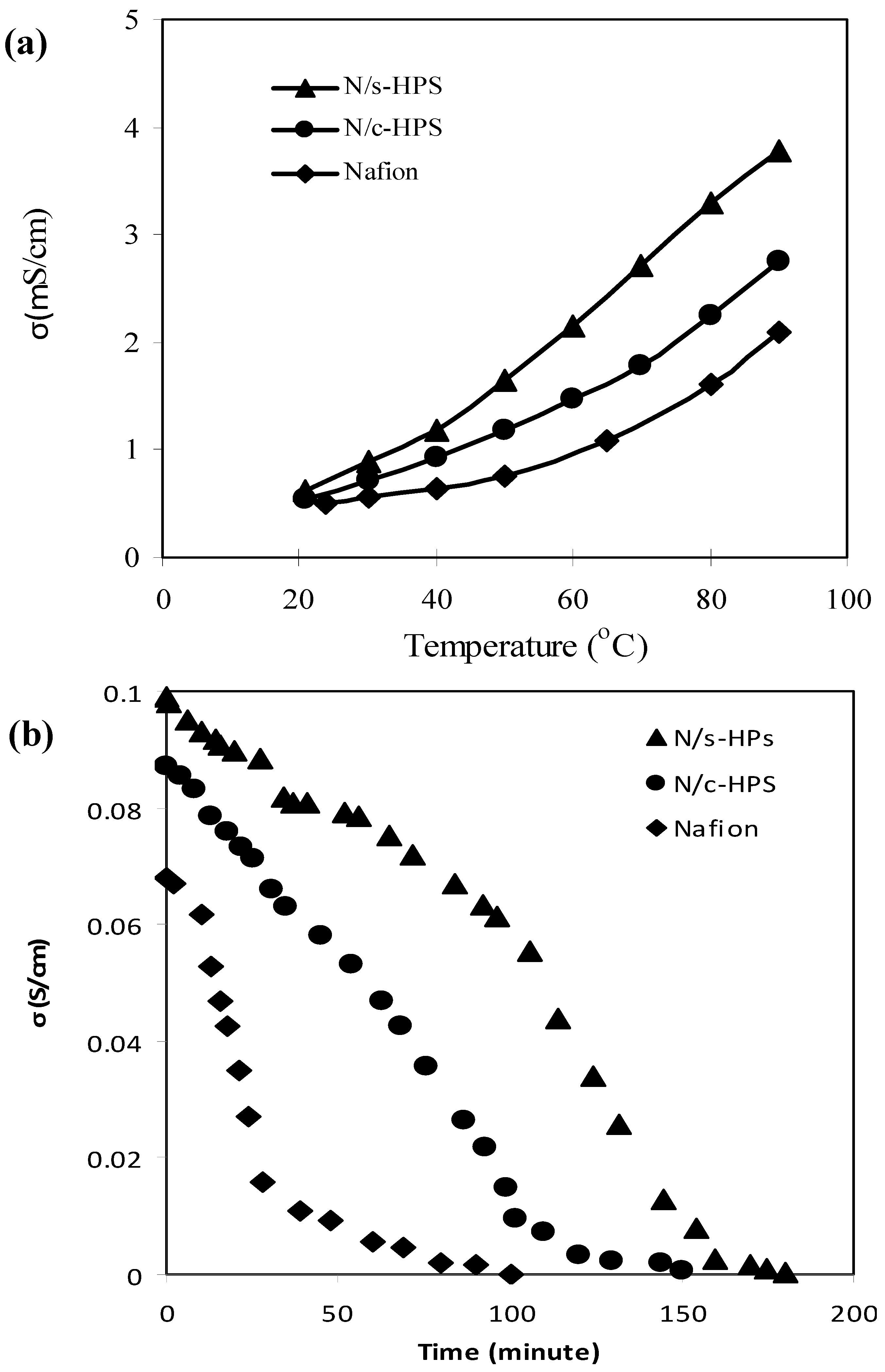
3.4. Influence of Moisture Level on Proton Transport in the Composite Membranes

The above study on water uptake, condensed state of water, and IEC comes to the conclusion: both s-HPS and c-HPS participated in restructuring hydrophilic channel in Nafion matrix, entrapped additional amount of water in the tiny cavities, and functioned as supplement pendant acid sites. Similar phenomena were also observed previously [43,44]. The enhancement of water reservation and reachability of acid sites on proton transport and electrochemical polarization was examined in this section. Figure 7 investigated variation of proton conductivity of the three membranes with temperature at 100% RH. A clear sequence of N/s-HPS > N/c-HPS > Nafion was presented over the temperature range (25–95 °C). This sequence is consistent with the water uptake, which favored the Grotthuss or hopping mechanism, and with the density of acid groups, which enhanced proton flux and possibly the vehicle mechanism [45]. Regarding the superior conductivity of N/s-HPS over N/c-HPS, the stronger –SO3H (based on ionization constant Ka) than –CO2H is an additional factor besides the above two.
Figure 7. The proton conductivity–temperature relation of the various membranes under 100% RH.
Polymers 04 01499 g007
Following the examination on the water uptake under various RH% (Figure 5), the three membranes revealed different rising trends of proton conductivity with the increase in temperature from 20 to 90 °C under constant 10% RH (Figure 8a). In such a chamber, the membranes captured just 6–9 wt % water at 20 °C and the bulk moisture levels would be lower than this range at higher temperatures. This test demonstrated the impact of the bound acid groups as well as the structure of hydrophilic channel on transport of protons because the Grotthuss mechanism became subsidiary at such moisture level. The conductivity values though show the order of magnitude of −3 under 10% RH, the discrepancies of them tell the capability of shipping protons by pendant acid groups, –SO3H and –CO2H. The N/s-HPS membrane presented the strongest capability of shipping protons through contact of spherical surface (Scheme 2) because this two-dimensional mould is far more efficient than transport along tangled polymer chains. A similar test was conducted to collate the proton-conductivity decreasing profile with the measurement time under 10% RH and at 20 °C (Figure 8b).
Figure 8. Examination of water retention capability of the membranes under 10% RH: (a) the effect of temperature and (b) the effect of exposing time at 20 °C.
Polymers 04 01499 g008
In this test, a fully hydrated membrane sample was employed at the beginning of test. The capability of deferring moisture evaporation as well as maintaining proton transport with decreasing of bulk humidity was assessed. Taking the conductivity values at 110 min as example, N/s-HPS held a conductivity of at least 5 times greater than N/c-HPS, while the Nafion membrane became almost non-proton conductive. This sequence is consistent with that displayed in Figure 5, in which water-retention power originates from the content of freezable water (Table 1) since it reflects the impact of micro-environment, including size of cavity and the type of acid group the hydrophilic shell bears, on water-retention capability of the membrane.
Unlike the proton conductivity measurement that reveals the structural effect on small proton flux, the electrochemical polarization curve of a single H2-PEMFC manifests the capability of the loaded membrane to sustain a larger stream of protons. Figure 9a displays the polarization curves of the four membranes including the commercial Nafion N-112 membrane at 20 °C without external humidification. The two composite membranes held higher cell voltages with the increase in current density than the two pristine Nafion membranes. It is considered that the differences in the water uptakes amid the membranes (at 20 °C in Table 1) played the main role. The hydrophilic channels, constructed by the –SO3H groups of Nafion and either s-HPS or c-HPS, can sustain higher proton flux than that of its pristine counterpart. With raising the single cell operation temperature to 70 °C (Figure 9b), the N/s-HPS membrane sustained the maximum power density of 525 mW/cm2, representing an increment of 106% against the utmost value of 255 mW/cm2 obtained at 20 °C. In contrast to this, the Nafion membrane achieved only an increment of 73% through this temperature rise.
Figure 9. Comparison of the polarization curves of H2-PEMFC (proton exchange membrane fuel cell) loaded with the various membranes at (a) 20 °C and (b) 70 °C.
Polymers 04 01499 g009
As shown in the water-uptake/temperature measurement (Figure 5a), these two membranes had about 11 wt % difference in water uptake at 70 °C, responsible for the different energy output. The other important factor is the different proton transport efficiency as observed in examining conductivity under 10% RH. The N-112 membrane also possessed a lower power density than that of the composite membranes, validating the impact of the above two factors that originates from the structure of hydrophilic channel.

4. Conclusions

Two composite membranes were fabricated by incorporating hollow polymer spheres (HPS) with a hydrophilic shell bearing sulfonic (s-HPS) or carboxylic groups (c-HPS) into Nafion polymer matrix using the solution cast approach. The very low specific mass of HPS permits a high volume faction of HPS in the composite membranes on the basis of 0.5 wt % loading. The resulting composite membranes attained a combinatory hydrophilic channel comprising the pendant –SO3H groups of Nafion and hydrophilic HPS with the unperturbed perfluoropolymer phase. This combinatory hydrophilic channel functioned much more effectively than that in the native Nafion membranes in transporting protons, in particular under low humidity conditions or at the medium temperatures (~70–100 °C). This improvement can be attributed to both strong water-retention capability and spherical-surface-sustained proton conduction path. Of the two types of hydrophilic HPS, the s-HPS worked more effectively than the c-HPS in augmenting proton transport on the basis of different water uptake extents and acidities. The influence of temperature (at 100% RH) and humidity (at 20 °C) on proton conduction was investigated to demonstrate the water micro-reservoir role of the two HPS in the composite membranes. Both composite membranes, N/s-HPS and N/c-HPS, offered obviously superior fuel cell performance over the commercial N-112 membrane at 70 °C.

References

  1. Mauritz, K.A.; Moore, R.B. State of understanding of Nafion. Chem. Rev. 2004, 104, 4535–4586. [Google Scholar] [CrossRef]
  2. Devanathan, R. Recent developments in proton exchange membranes for fuel cells. Energ. Environ. Sci. 2008, 1, 101–119. [Google Scholar] [CrossRef]
  3. Alberti, G.; Casciola, M. Composite membranes for medium-temperature PEM fuel cells. Annu. Rev. Mater. Res. 2003, 33, 129–154. [Google Scholar] [CrossRef]
  4. Hickner, M.A. Ion-contaning polymers: New energy & clean water. Mater. Today 2010, 13, 34–41. [Google Scholar] [CrossRef]
  5. Lee, S.Y.; Scharfenberger, G.; Meyer, W.H.; Wegener, G. A novel water-free proton-conducting solid electrolyte based on an organic/inorganic hybrid. Adv. Mater. 2005, 17, 626–630. [Google Scholar] [CrossRef]
  6. Zhang, Y.; Zhang, H.M.; Zhu, X.B.; Bi, C. Promotion of PEM self-humidifying effect by nanometer-sized sulfated zirconia-supported Pt catalyst hybrid with sulfonated poly(ether ether ketone). J. Phys. Chem.B 2007, 111, 6391–6399. [Google Scholar]
  7. Chen, Z.; Holmberg, B.; Li, W.; Wang, X.; Deng, W.; Munoz, R.; Yan, Y.S. Nafion/zeolite nanocomposite membrane by in situ crystallization for a direct methanol fuel cell. Chem. Mater. 2006, 18, 5669–5675. [Google Scholar] [CrossRef]
  8. Garrido, L.; Pozuelo, J.; López-González, M.; Fang, J.; Riande, E. Simulation and experimental studies on proton diffusion in polyelectrolytes based on sulfonated naphthalenic copolyimides. Macromolecules 2009, 42, 6572–6580. [Google Scholar]
  9. Park, M.J.; Downing, K.H.; Jackson, A. Increased water retention in polymer electrolyte membranes at elevated temperature assisted by capillary condensation. Nano Lett. 2007, 7, 3547–3552. [Google Scholar] [CrossRef]
  10. Shao, Z.G.; Joghee, P.; Hsing, M. Preparation and chacterization of hybrid Nafion-silica membrane doped with phosphotungstic acid for high temperature operation of proton exchange membrane fuel cells. J. Membr. Sci. 2004, 229, 43–51. [Google Scholar] [CrossRef]
  11. Pereira, F.; Valle, K.; Belleville, P.; Morin, A.; Lambert, S.; Sanchez, C. Advanced mesostructured hybrid silica-Nafion membranes for high-performance PEM fuel cell. Chem. Mater. 2008, 20, 1710–1718. [Google Scholar]
  12. Adjemian, K.T.; Dominey, R.; Krishnan, L.; Ota, H.; Majsztrik, P.; Zhang, T.; Mann, J.; Kirby, B.; Gatto, L.; Velo-Simpson, M.; Leahy, J.; Srinivasan, S.; Benziger, J.B.; Bocarsly, A.B. Function and characterization of metak oxide-Nafion composite membranes for elevated-temperature H2/O2 PEM fuel cells. Chem. Mater. 2006, 18, 2238–2248. [Google Scholar]
  13. Tay, S.W.; Zhang, X.H.; Liu, Z.L.; Hong, L. Composite Nafion® membrane embedded with hybrid nanofillers for promoting direct methanol fuel cell performance. J. Membr. Sci. 2008, 321, 139–145. [Google Scholar] [CrossRef]
  14. Zhang, X.; Hong, L.; Liu, Z.; Lee, J.Y. Interfacial behavior of densely anchored hydrophilic oligomeric chains on silica microspheres. Colloid. Polym. Sci. 2008, 286, 1351–1360. [Google Scholar]
  15. Santiago, E.I.; Isidoro, R.A.; Dresch, M.A.; Matos, B.R.; Linardi, M.; Fonseca, F.C. Nafion-TiO2 hybrid electrolytes for stable operation of PEM fuel cells at high temperature. Electrochim. Acta. 2009, 54, 4111–4117. [Google Scholar]
  16. Yuan, J.J.; Zhou, G.B.; Pu, H.T. Preparation and properties of Nafion®/hollow silica spheres composite membranes. J. Membr. Sci. 2008, 325, 742–748. [Google Scholar] [CrossRef]
  17. Pu, H.T.; Wang, D.; Yang, Z.L. Towards high water retention of proton exchange membranes at elevated temperature via hollow nanospheres. J. Membr. Sci. 2010, 360, 123–129. [Google Scholar] [CrossRef]
  18. Lou, L.D.; Pu, H.T. preparation and properties of proton exchange membranes based on Nafion and phosphonic aicd-functionalized hollow silica spheres. Int. J. Hydro. Energy. 2011, 36, 3123–3130. [Google Scholar]
  19. Wang, J.T.; Zhang, H.; Yang, X.L.; Jiang, S.; Lv, W.J.; Jiang, Z.Y.; Qiao, S.Z. Enhanced water retention by using polymeric microcapsules to confer high proton conductivity on membranes at low humidity. Adv. Funct. Mater. 2011, 21, 971–978. [Google Scholar] [CrossRef]
  20. Yuan, J.J.; Pu, H.T.; Yang, Z.L. Studies on sulfonic acid functionalized hollow silica spheres (SAFHSS)/Nafion®112 composite proton exchange membranes. J. Polym. Sci. A Polym. Chem. 2009, 47, 2647–2655. [Google Scholar]
  21. Pu, H.T.; Lou, L.D.; Guan, Y.S.; Chang, Z.H. Proton exchange membranes based on semi-interpenetrating polymer networks of polybenzimidazole and perfluorosulfonic acid polymer with hollow silica spheres as micro-reservoir. J. Membr. Sci. 2012, in press. [Google Scholar]
  22. Omidian, H.; Rocca, J.G.; Park, K. Advances in superporous hydrogels. J. Controlled Release 2005, 102, 3–12. [Google Scholar] [CrossRef]
  23. Gemeinhart, R.A.; Chen, J.; Park, H.; Park, K. pH-sensitivity of fast responsive superporous hydrogels. J. Biomater. Sci. Polym. Ed. 2000, 11, 1371–1380. [Google Scholar] [CrossRef]
  24. Kannan, R.; Kakade, B.A.; Pillai, V.K. Polymer electrolyte fuel cells using Nafion-based composite membanes with functionalized carbon nanotubes. Angew. Chem. Int. Ed. 2008, 47, 2653–2656. [Google Scholar]
  25. Li, G.L.; Liu, G.; Kang, E.T.; Neoh, K.G.; Yang, X.L. pH-responsive hollow polymeric microspheres and concentric hollow silica microspheres from silica-polymer core-shell microspheres. Langmuir 2008, 24, 9050–9055. [Google Scholar] [CrossRef]
  26. Stöber, W.; Fink, A.; Bohn, E. Controlled growth of monodispersed silica spheres in the micron size. J. Colloid. Interface Sci. 1968, 26, 62–69. [Google Scholar] [CrossRef]
  27. Bourgeat-Lami, E.; Lang, J. Encapsulation of inorganic particles by dispersion polymerization in polar media: 1. silica nanoparticles encapsulated by polystyrene. J. Colloid. Interface Sci. 1998, 197, 293–308. [Google Scholar] [CrossRef]
  28. lvarez-Gallego, Y.; de Heer, M.P. Sub-freezing conductivity of PFSA membranes. Fuel Cells 2009, 9, 421–431. [Google Scholar] [CrossRef]
  29. Saito, M.; Hayamizu, K.; Okada, T. Temperature dependence of ion and water transport in perfluorinated ionomer membranes for fuel cells. J. Phys. Chem. B 2005, 109, 3112–3119. [Google Scholar] [CrossRef]
  30. Hou, J.; Yu, H.; Wang, L.; Zhou, D.X.; Ming, P.; Shao, Z.; Yi, B. Conductivity of aromatic-based proton exchange membranes at subzero temperatures. J. Power Sources 2008, 180, 232–237. [Google Scholar] [CrossRef]
  31. Guo, B.; Liu, Z.L.; Hong, L. Doping Nafion® matrix by p-aramide flakes for a proton transport less reliance on moisture. J. Mater. Chem. 2011, 21, 12414–12421. [Google Scholar]
  32. Guo, B.; Liu, Z.L.; Hong, L. Substituted poly(p-phenylene) oligomer as a physical crosslinker in Nafion® membrane. J. Membr. Sci. 2011, 379, 279–286. [Google Scholar] [CrossRef]
  33. Tsang, E.M.W.; Zhang, Z.; Shi, Z.; Soboleva, T.; Holdcroft, S. Considerations of macromolecular structure in the design of proton conducting polymer membranes: Graft versus diblock polyelectrolytes. J. Am. Chem. Soc. 2007, 129, 15106–15107. [Google Scholar]
  34. Eikerling, M.; Kornyshev, A.A.; Kuznetsov, A.M.; Ulstrup, J.; Walbran, S. Mechanisms of proton conductance in polymer electrolyte membranes. J. Phys. Chem. B 2001, 105, 3646–3662. [Google Scholar] [CrossRef]
  35. Kornshev, A.A.; Kuznetsov, A.M.; Spohr, E.; Ulstrup, J. Kinetics of proton transport in water. J. Phys. Chem. B 2003, 107, 3351–3366. [Google Scholar]
  36. Spohr, E.; Commer, P.; Kornyshev, A.A. Enhancing proton mobility in polymer electrolyte membranes: lessopns from molecular dynamics simulations. J. Phys. Chem. B 2002, 106, 10560–10569. [Google Scholar] [CrossRef]
  37. Kalapos, T.L.; Decker, B.; Every, H.A.; Ghassemi, H.; Zawodzinski, T.A., Jr. Thermal studies of the state of water in proton conducting fuel cell membranes. J. Power Sources 2007, 172, 14–19. [Google Scholar] [CrossRef]
  38. Lue, S.J.; Shieh, S.J. Water states in perflurosulfonic acid membranes using differential scanning calorimetry. J. Macromol. Sci. B Phys. 2009, 48, 114–127. [Google Scholar] [CrossRef]
  39. Chen, W.F.; Kuo, P.L. Covalently cross-linked perfluorosulfonated membranes with polysiloxane framework. Macromolecules 2007, 40, 1987–1994. [Google Scholar] [CrossRef]
  40. Zhang, W.Z.; Satoh, M.; Komiyama, J. A differential scanning calorimetry study of the states of water in swollen poly(vinyl alcohol) membranes containing nonvolatile additives. J. Membr. Sci. 1989, 42, 303–314. [Google Scholar] [CrossRef]
  41. Gupta, B.; Büchi, F.N.; Staub, M.; Grman, D.; Scherer, G.G. Cation exchange membranes by pre-irradiation grafting of styrene into FEP films. II. Properties of copolymer membranes. J. Polym. Sci. A Polym. Chem. 1996, 34, 1873–1880. [Google Scholar] [CrossRef]
  42. Lee, C.H.; Park, H.B.; Chung, Y.S.; Lee, Y.M.; Freeman, B.D. Water sorption, proton conduction, and methanol permeation properties of sulfonated polyimide membranes cross-linked with N,N-Bis(2-hydroxyethyl)-2-aminoethanesulfonic acid (BES). Macromolecules 2006, 39, 755–764. [Google Scholar] [CrossRef]
  43. Su, Y.H.; Liu, Y.L.; Sun, Y.M.; Lai, J.Y.; Wang, D.M.; Gao, Y.; Liu, B.; Guiver, M.D. Proton exchange membranes modified with sulfonated silica nanoparticles for direct methanol fuel cells. J. Membr. Sci. 2007, 296, 21–28. [Google Scholar] [CrossRef]
  44. Lafitte, B.; Jannasch, P. Proton-conducting aromatic polymers carrying hypersulfonated side chains for fuel cell applications. Adv. Funct. Mater. 2007, 17, 2823–2834. [Google Scholar] [CrossRef]
  45. Kreuer, K.D.; Paddison, S.J.; Spohr, E.; Schuster, M. Transport in proton conductors for fuel-cell applications: Simulations, elementary reactions, and phenomenolog. Chem. Rev. 2004, 104, 4637–4678. [Google Scholar] [CrossRef] [Green Version]

