

Theoretical and Experimental Study on the Surface Microstructures of Polyimide in Ultra-Precision Fly-Cutting


Abstract

1. Introduction
2. Theoretical Analysis
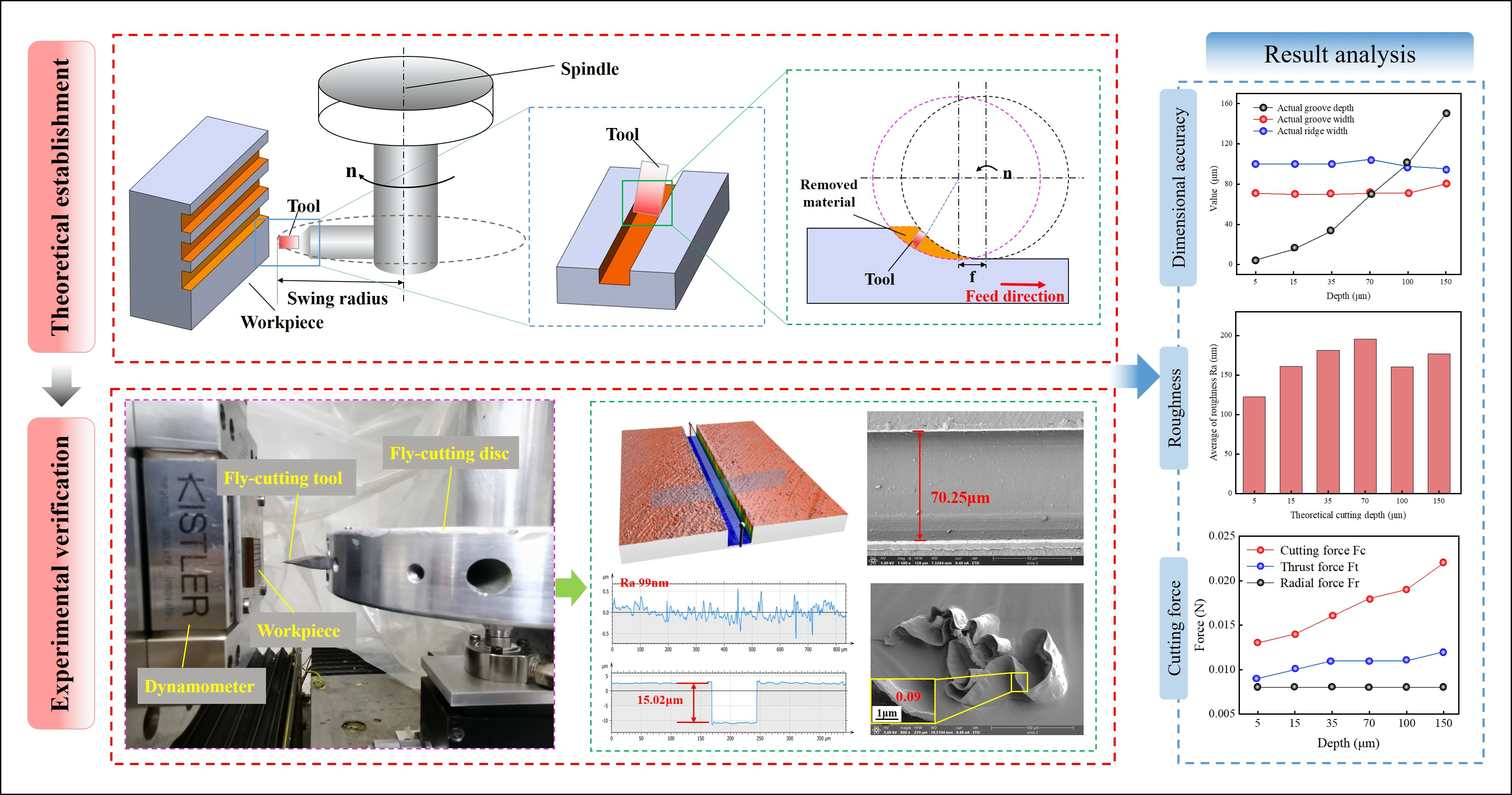
2.1. Machining Principles
2.2. Trajectory Method and Profiling Method
2.3. Cutting Strategy
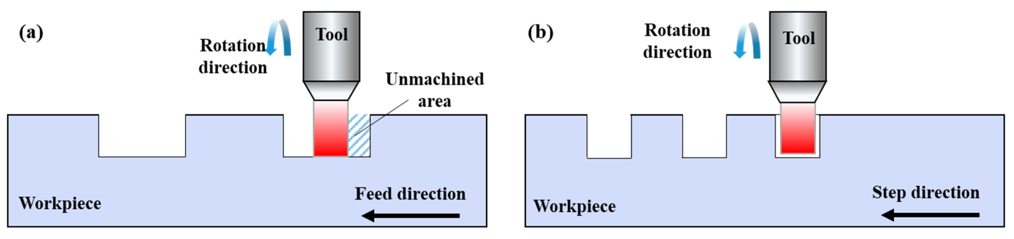
2.3.1. Horizontal and Vertical Cutting
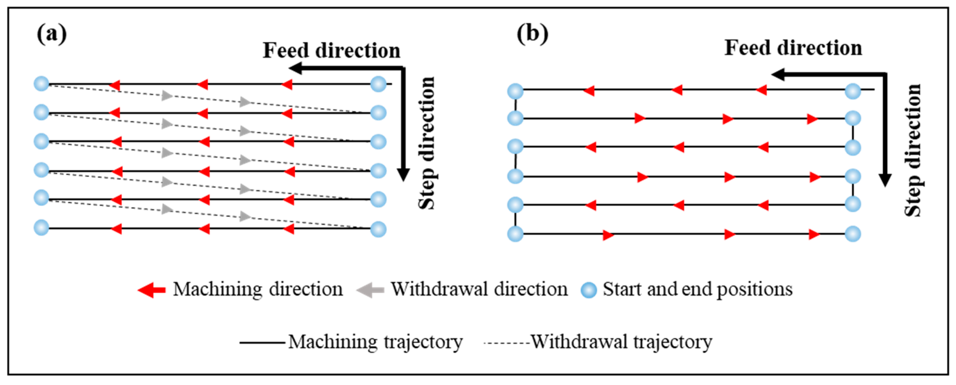
2.3.2. Unidirectional and Bidirectional Cutting
2.3.3. Climb and Conventional Cutting
2.4. Kinematic Analysis
2.5. Maximum Cutting Thickness Model
2.5.1. Chip Thickness Model and Theoretical Calculation
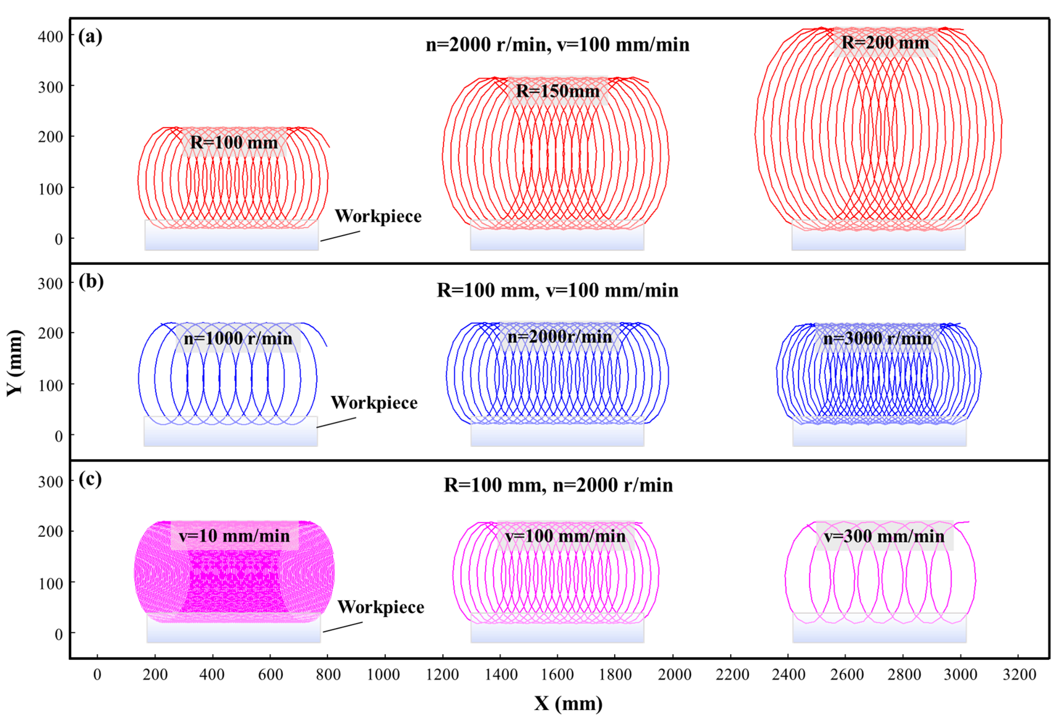
2.5.2. Influence of Process Parameters on the Maximum Cutting Thickness
3. Materials and Methodology
3.1. Materials
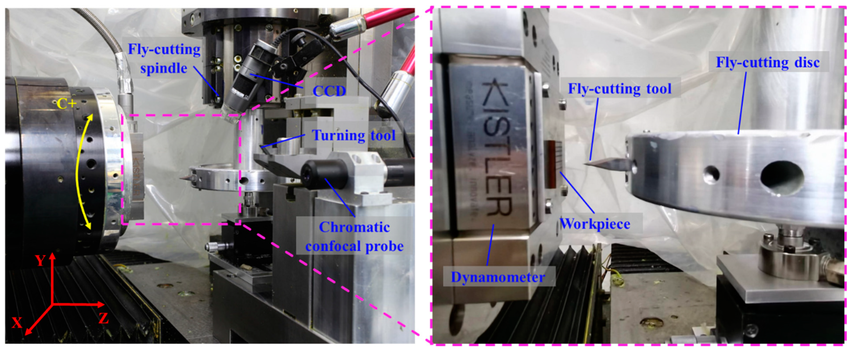
3.2. Experimental Setup
3.3. Characterization and Evaluation
4. Results and Discussions
4.1. Analysis of Climb Cutting and Conventional Cutting
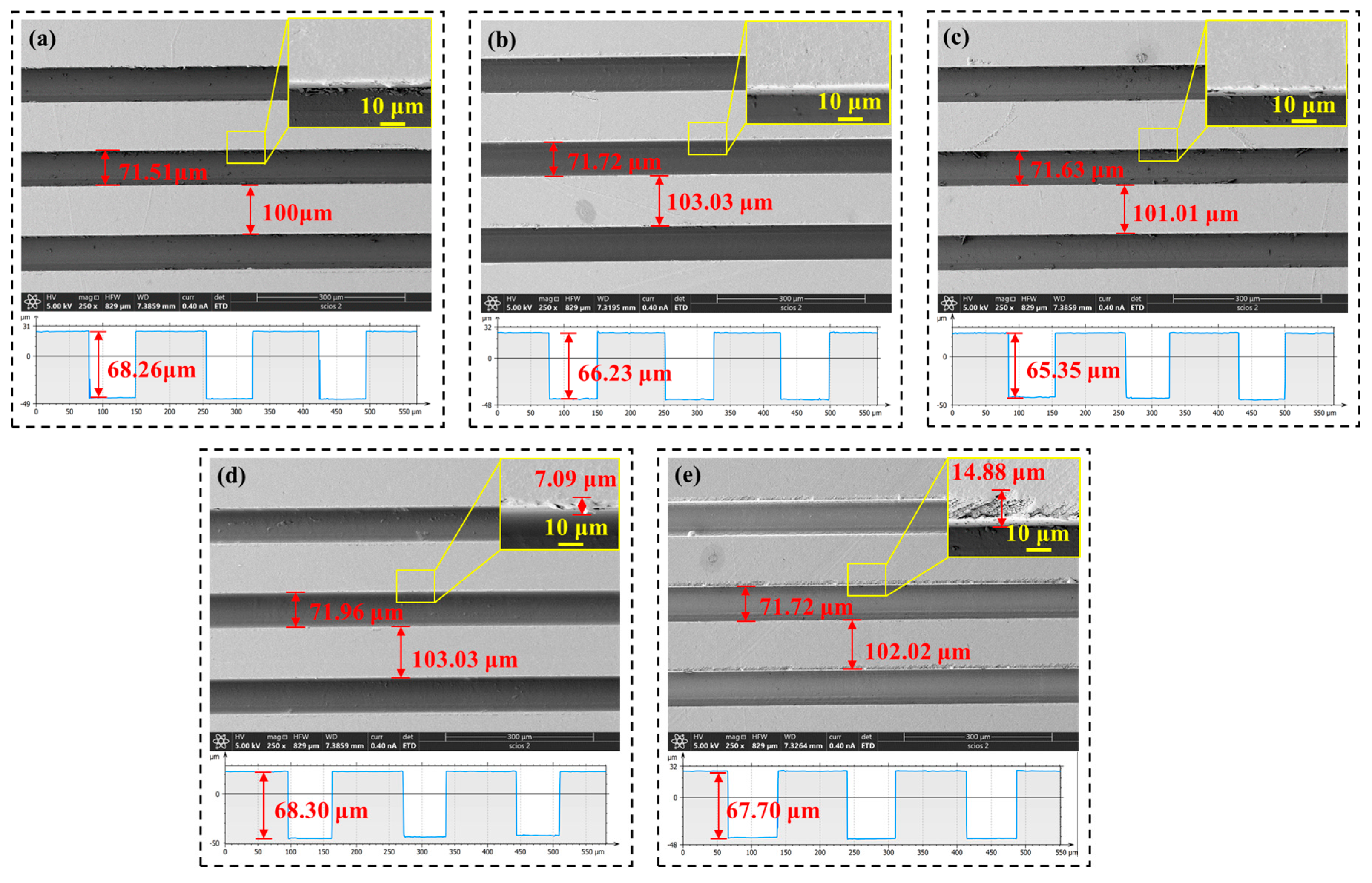
4.2. Microstructure Morphology and Profile
4.3. Roughness
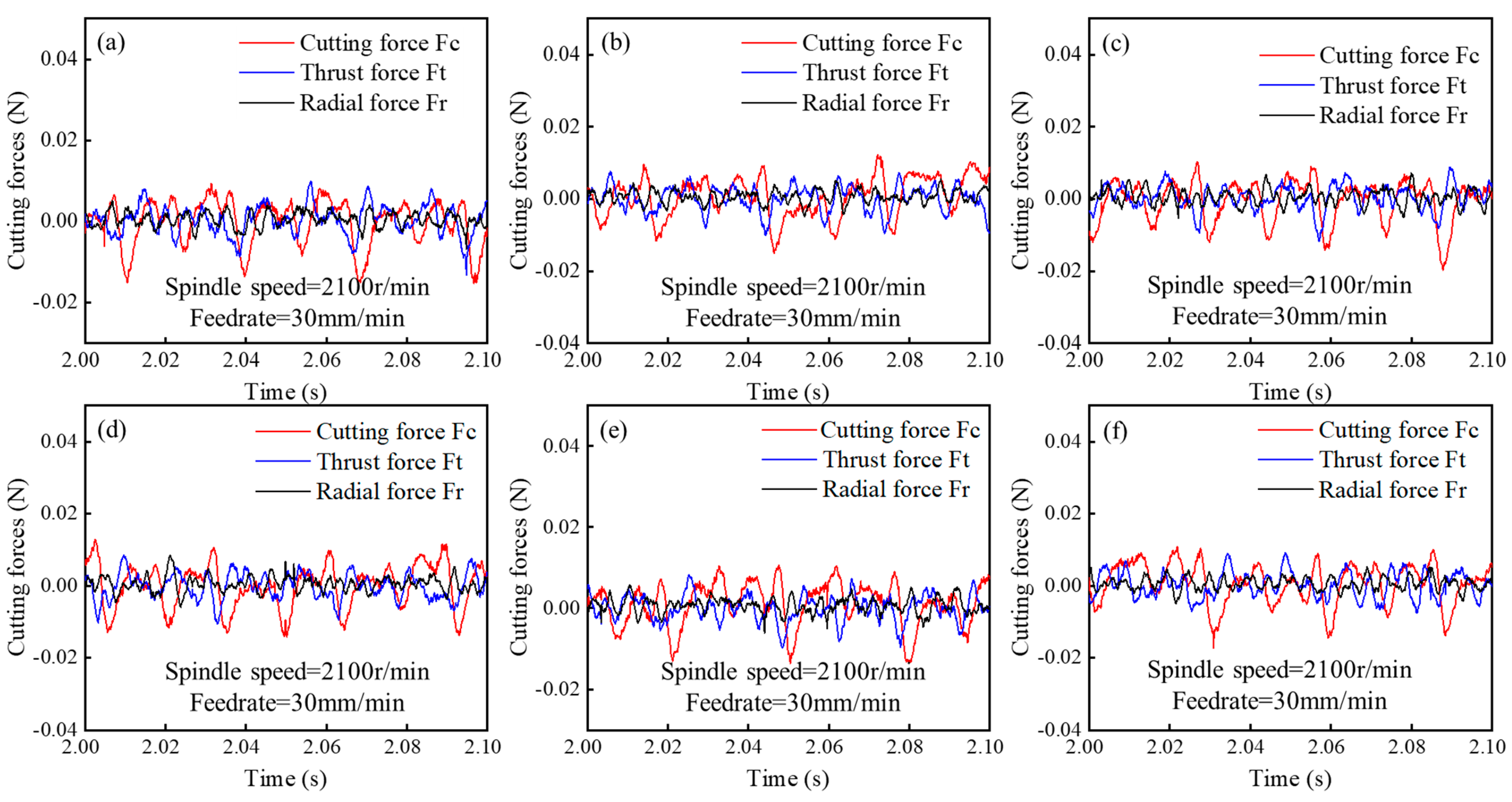
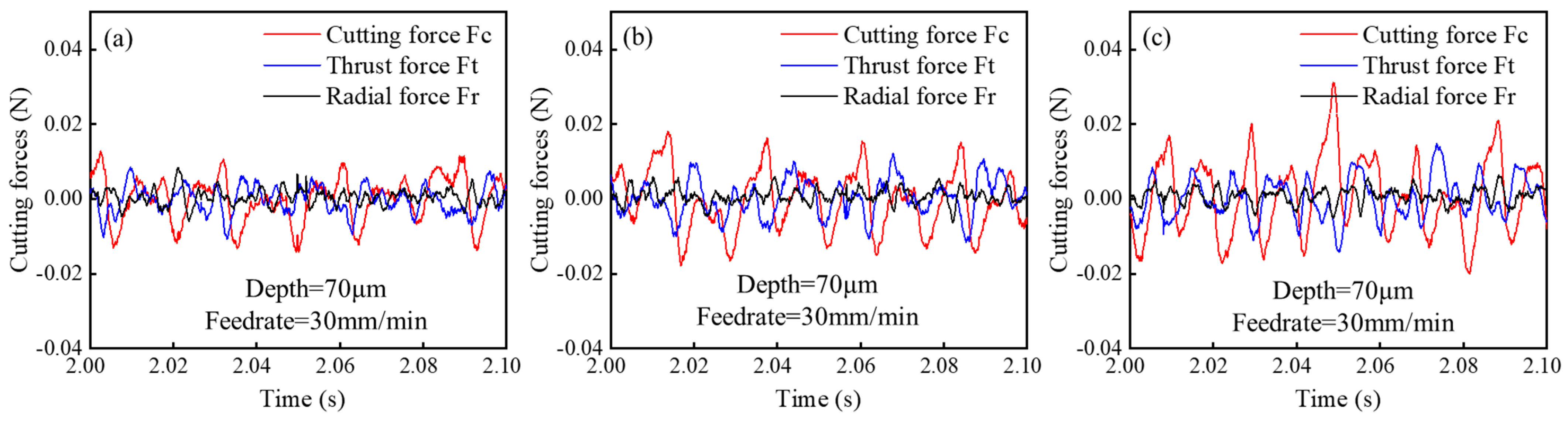
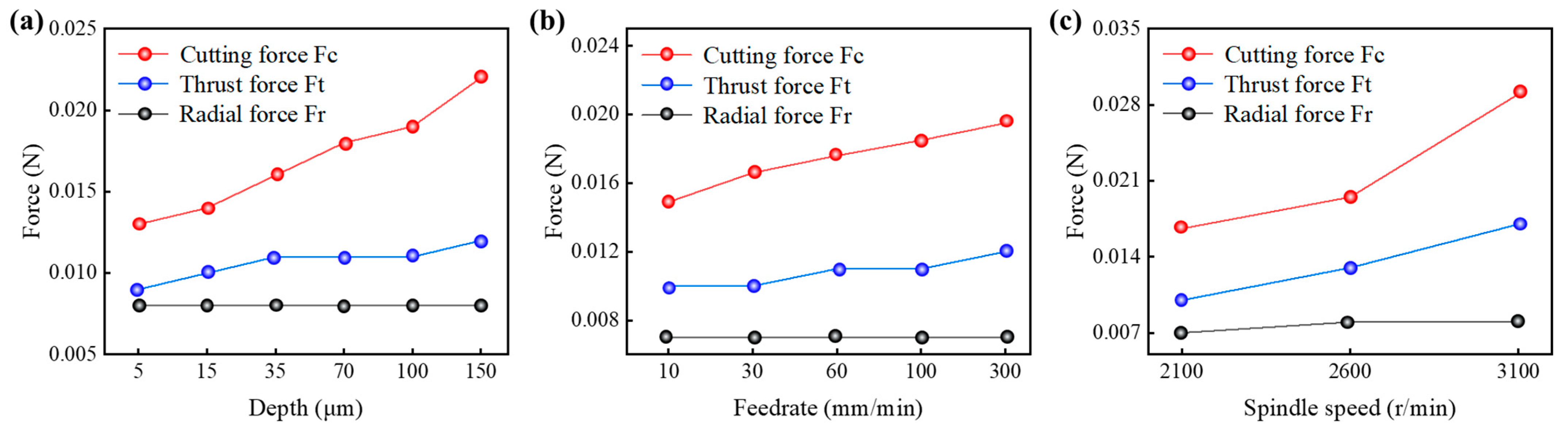
4.4. Cutting Force
4.5. Chip Morphology
5. Conclusions
Author Contributions
Funding
Data Availability Statement
Conflicts of Interest
References
- Gao, J.; Xu, Z.; Lei, Y.; Huang, S. Fly-cutting Processing of Micro-triangular Pyramid Arrays and Synchronous Micro-scrap Removal. Micromachines 2024, 15, 655. [Google Scholar] [CrossRef] [PubMed]
- Liu, B.; Jiang, K.; Chen, Y.; Yang, H.; Wang, Y.; Sun, K.; Li, H. Simulated and Experimental Study of the Chip Deformation Mechanisms of Monocrystalline Cu. Nanotechnol. Precis. Eng. 2025, 8, 013007. [Google Scholar] [CrossRef]
- Aborkin, A.; Prusov, E.; Deev, V.; Babin, D.; Bokaryov, D.; Ryabkova, V. Structure and Mechanical Properties of Consolidated Billets From Recycled Chip Wastes of Cast Metal Matrix Composites of the Al-Si-SiC System. J. Alloys Compd. 2025, 1010, 177059. [Google Scholar] [CrossRef]
- Yang, H.D.; Zhang, L.B.; Li, H.D.; Zhang, J.S.; Tang, H.H.; Chen, S.H. Influence of Tool Corner Radius on Chip Geometrical Characteristics of Machining Zr-based Bulk Metallic Glass. J. Adv. Manuf. Sci. Technol. 2025, 5, 2025012. [Google Scholar] [CrossRef]
- Zhang, S.J.; Zhou, Y.P.; Zhang, H.J.; Xiong, Z.W.; To, S. Advances in Ultra-precision Machining of Micro-structured Functional Surfaces and Their Typical Applications. Int. J. Mach. Tool. Manuf. 2019, 142, 16–41. [Google Scholar] [CrossRef]
- Gao, J.S.; Lei, Y.; Xu, Z.L. Research on Micro-Triangular Pyramid Array-Based Fly-Cutting Technology Using the Orthogonal Test Method. Coatings 2024, 14, 806. [Google Scholar] [CrossRef]
- Lu, H.; Ma, Z.; Chen, G. Dynamic Simulation and Active Vibration Control Design of an Ultra-precision Fly-cutting Machine Tool. Int. J. Adv. Manuf. Technol. 2024, 133, 4663–4678. [Google Scholar] [CrossRef]
- Ding, Y.; Rui, X.; Chen, Y. Theoretical and Experimental Investigation on the Surface Stripes Formation in Ultra-precision Fly Cutting Machining. Int. J. Adv. Manuf. Technol. 2023, 124, 1041–1063. [Google Scholar] [CrossRef]
- Kong, L.B.; Cheung, C.F.; To, S.; Lee, W. An Investigation into Surface Generation in Ultra-precision Raster Milling. J. Mater. Process. Technol. 2009, 209, 4178–4185. [Google Scholar] [CrossRef]
- Kong, L.B.; Cheung, C.F. Prediction of Surface Generation in Ultra-precision Raster Milling of Optical Freeform Surfaces Using an Integrated Kinematics Error Model. Adv. Eng. Softw. 2012, 45, 124–136. [Google Scholar] [CrossRef]
- Wang, H.T.; Lee, W.B.; Chan, J.; To, S. Numerical and Eexperimental Analysis of Heat Transfer in Turbulent Flow Channels With Two-dimensional Ribs. Appl. Therm. Eng. 2015, 75, 623–634. [Google Scholar] [CrossRef]
- Cheng, C.T.; Zhang, G.Q.; To, S. Wetting Characteristics of Bare Micro-patterned Cyclic Olefin Copolymer Surfaces Fabricated by Ultra-precision Raster Milling. RSC Adv. 2016, 6, 1562–1570. [Google Scholar] [CrossRef]
- Wu, Y.L.; Peng, W.Q.; Liu, Y. A Novel Fabrication Method for Micro Optical Waveguide Mold Based on Fly-cutting Technology. Optik 2013, 124, 867–869. [Google Scholar] [CrossRef]
- Wang, H.T.; Chen, W.; Zhao, W.; Wu, H.M. Numerical and Experimental Study on the Optical Performance of Micro-pyramid Functional Surfaces. Microsyst. Technol. 2021, 27, 2671–2678. [Google Scholar] [CrossRef]
- Zhang, G.Q.; Ma, S.; Wang, J.P.; Jiang, J.K.; Luo, T.; Wang, H.T. Offset-tool-servo Diamond End Flycutting Multi-layer Hierarchical Microstructures. Int. J. Mech. Sci. 2022, 233, 107645. [Google Scholar] [CrossRef]
- Yang, Y.; Chen, Y.; Wen, J.; Zhao, C. Proposal of Trapezoidal Vibration-assisted Diamond Cutting for Ductile-regime Machining of Brittle Crystals: A Case Study on KDP Crystal. J. Mater. Process. Technol. 2024, 332, 118562. [Google Scholar] [CrossRef]
- Liu, C.; Wu, C.; Li, X.; Hou, B.; Wang, G.; Wu, J.; Sun, R.; Chen, M. Modeling and Analysis of Radial Throw of Micro-milling Tool Based on Tool-attachment Errors in High-speed Rotating. J. Manuf. Process. 2023, 108, 779–790. [Google Scholar] [CrossRef]
- Liu, Q.; Cheng, J.; Liao, Z.; Luo, X.; Yang, Y.; Li, M.; Yang, H.; Tan, C.; Wang, G.; Ding, W.; et al. Research on the Light Intensity Modulation and Characterizing Methods of Surface Texture on KDP Optics Generated in Fly-cutting and Micro Ball-end Milling Processes. CIRP Ann. Manuf. Technol. 2023, 41, 30–43. [Google Scholar] [CrossRef]
- Chen, W.; Liang, Y.; Sun, Y.; Huo, D.; Lu, L.; Liu, H. Design Philosophy of an Ultra-precision Fly Cutting Machine Tool for KDP Crystal Machining and Its Implementation on the Structure Design. Int. J. Adv. Manuf. Technol. 2014, 70, 429–438. [Google Scholar] [CrossRef]
- Chen, D.; Li, S.; Fan, J. Effect of KDP-Crystal Material Properties on Surface Morphology in Ultra-Precision Fly Cutting. Micromachines 2020, 11, 802. [Google Scholar] [CrossRef] [PubMed]
- Yang, S.; Zhang, L. Advancing Damage-free Machining of KDP: A Comprehensive Review. J. Am. Ceram. Soc. 2024, 108, e20341. [Google Scholar] [CrossRef]
- Zhu, Z.; To, S.; Zhang, S. Theoretical and Experimental Investigation on the Novel End-fly-cutting-servo Diamond Machining of Hierarchical Micro-na-nostructures. Int. J. Mach. Tools. Manuf. 2015, 94, 15–25. [Google Scholar] [CrossRef]
- Zhu, W.L.; Duan, F.; Zhang, X.; Zhu, Z.; Ju, B.F. A New Diamond Machining Approach for Extendable Fabrication of Micro-freeform Lens Array. Int. J. Mach. Tools. Manuf. 2018, 124, 134–148. [Google Scholar] [CrossRef]
- Liu, H.; Yan, Y.; Cui, J.; Geng, Y.; Sun, T.; Luo, X.; Zong, W. Recent Advances in Design and Preparation of Micro Diamond Cutting Tools. Int. J. Extrem. Manuf. 2024, 6, 062008. [Google Scholar] [CrossRef]
- Guo, Q.; Liu, Z.; Yang, Z.; Jiang, Y.; Sun, Y.; Xu, J.; Zhao, W.; Wang, W.; Wang, W.; Ren, Q.; et al. Development, Challenges and Future Trends on the Fabrication of Micro-textured Surfaces Using Milling Technology. J. Manuf. Process. 2024, 126, 285–331. [Google Scholar] [CrossRef]
- Sun, Z.; To, S.; Yu, K.M. An Investigation in the Ultra-precision Fly Cutting of Freeform Surfaces on Brittle Materials With High Machining Efficiency and Low Tool Wear. Int. J. Adv. Manuf. Technol. 2019, 101, 1583–1593. [Google Scholar] [CrossRef]
- Zhou, R.; Kong, L. A Study of Ultra-precision Raster Milling of Optical Freeform Surfaces. In Proceedings of the Seventh Asia Pacific Conference on Optics Manufacture and 2021 International Forum of Young Scientists on Advanced Optical Manufacturing, Shanghai, China, 28–31 October 2021. [Google Scholar] [CrossRef]
- Cheng, M.N.; Cheung, C.F.; Lee, W.B.; To, S. A Study of Factors Affecting Surface Quality in Ultra-Precision Raster Milling. Key Eng. Mater. 2007, 339, 400–406. [Google Scholar] [CrossRef]
- Wang, S.J. Modelling and Optimization of Cutting Strategy and Surface Gen-Eration in Ultra-Precision Raster Milling. Ph.D. Thesis, The Hong KongPolytechnic University, Hong Kong, 2011. [Google Scholar]
- Wang, S.J.; To, S.; Cheung, C.F. An Investigation into Material-induced Surface Roughness in Ultra-precision Milling. Int. J. Adv. Manuf. Technol. 2013, 68, 607–616. [Google Scholar] [CrossRef]
- Wang, S.J.; To, S.; Cheung, C.F. Effect of Workpiece Material on Surface Roughness in Ultraprecision Raster Milling. Mater. Manuf. Process. 2012, 27, 1022–1028. [Google Scholar] [CrossRef]
- Cheng, M.N.; Cheung, C.F.; Lee, W.B.; To, S.; Kong, L.B. Theoretical and Experi-mental Analysis of Nano-surface Generation in Ultra-precision Raster Milling. Int. J. Mach. Tools Manuf. 2008, 48, 1090–1102. [Google Scholar] [CrossRef]
- Cheng, M.N. Optimization of Surface Generation in Ultra-Precision Multi-Axis Raster Milling. Master’s Thesis, The Hong Kong Polytechnic University, Hong Kong, 2006. [Google Scholar]
- Kong, L.B. Modeling of Ultra-Precision Raster Milling and Characterization of Optical Freeform Surface. Ph.D. Thesis, The Hong Kong Polytechnic University, Hong Kong, 2009. [Google Scholar]
- Zhang, G.Q.; To, S.; Xiao, G.B. Novel Tool Wear Monitoring Method in Ultra-precision Raster Milling Using Cutting Chips. Precis. Eng. 2014, 38, 555–560. [Google Scholar] [CrossRef]
- Zhang, G.Q.; To, S. A Novel Surface Quality Evaluation Method in Ultra-precision Raster Milling Using Cutting Chips. J. Mater. Process. Technol. 2014, 219, 328–338. [Google Scholar] [CrossRef]
- Zhang, G.Q.; To, S.; Xiao, G.B. The Relation Between Chip Morphology and Tool Wear in Ultra-precision Raster Milling. Int. J. Mach. Tools Manuf. 2014, 80–81, 11–17. [Google Scholar] [CrossRef]
- Zhao, Q.; Guo, B.; Yang, H.; Zhang, X. A Mechanistic Cutting Force Model for Diamond Fly-cutting of Microstructured Surface. In Proceedings of the Advanced Optical Manufacturing Technologies, International Society for Optics and Photonics, Chengdu, China, 19–21 November 2008; p. 728204. [Google Scholar] [CrossRef]
- To, S.; Zhang, G. Study of Cutting Force in Ultra-precision Raster Milling of V-groove. Int. J. Adv. Manuf. Technol. 2014, 75, 967–978. [Google Scholar] [CrossRef]
- Zhang, G.Q. Modelling and Experimental Investigation of Tool Wear in Ultra-Precision Rraster Milling. Ph.D. Thesis, The Hong Kong Polytechnic University, Hong Kong, 2014. [Google Scholar]
- Liu, J.; Wang, S.; Huo, Y.; Zhao, Q.; Wang, X.; Zhang, J. An Investigation of Ultra-precision Manufacturing Methods in Generating Functional Rectangular Microstructures on the Polymer Material of Molyimide. J. Mater. Res. Technol. 2024, 33, 8903–8917. [Google Scholar] [CrossRef]
- Seo, J.; Kim, D.C.; Park, H.; Kang, Y.S.; Park, H.W. Advancements and Challenges in the Carbon Fiber-Reinforced Polymer (CFRP) Trimming Process. Int. J. Precis. Eng. Manuf. Technol. 2024, 11, 1341–1360. [Google Scholar] [CrossRef]
- Noyel, J.P.; Hajjar, A.; Debastiani, R.; Antouly, K.; Atli, A. Impact of Viscoelasticity on the Sstiffness of Polymer Nanocomposites: Insights from Experimental and Micromechanical Model Approaches. Polymer 2024, 309, 127443. [Google Scholar] [CrossRef]
- Da, T.C.; Haveroth, G.A.; Bittencourt, M.L.; Boldrini, J.L. A Damage Phase-field Model for Fractional Viscoelastic Materials in Finite Strain. Comput. Mech. 2022, 69, 1365–1393. [Google Scholar] [CrossRef]
- HamaSur, S.A.; Abdalrahman, R.M. The Effect of Tool’s Rake Angles and Infeed in Turning Polyamide 66. Eng. Technol. Appl. Sci. Res. 2023, 13, 11204–11209. Available online: https://etasr.com/index.php/ETASR/article/view/5891 (accessed on 16 December 2024). [CrossRef]
- Zhang, S.J.; To, S.; Zhu, Z.W.; Zhang, G.Q. A Review of Fly Cutting Applied to Surface Generation in Ultra-precision Machining. Int. J. Mach. Tool. Manuf. 2016, 103, 13–27. [Google Scholar] [CrossRef]
- Guo, B.; Yu, X.; Zeng, Z.; Zhao, Q.; Xu, L.; Liu, X. Ultra-precision Cutting of Linear Micro-groove Array for Distributed Feedback Laser Devices. Int. J. Nanomanuf. 2018, 14, 9. [Google Scholar] [CrossRef]
- Ma, Y.; Zhang, G.; Cao, S.; Huo, Z.; Han, J.; Ma, S.; Huang, Z. A Review of Advances in Fabrication Methods and Assistive Technologies of Micro-Structured Surfaces. Processes 2023, 11, 1337. [Google Scholar] [CrossRef]
- Luo, X.; Cheng, K.; Webb, D.; Wardle, F. Design of Ultraprecision Machine Tools With Applications to Manufacture of Miniature and Micro Components. J. Mater. Process. Technol. 2005, 167, 515–528. [Google Scholar] [CrossRef]
- Cao, S.; Zhang, G.; Huang, Z.; Ma, Y.; Huo, Z.; Du, J. Generation of Uniform Micro-textured Structures by Two-dimensional Modulation Fly-cutting. J. Manuf. Process. 2024, 127, 238–250. [Google Scholar] [CrossRef]
- Lu, H.; Rui, X.; Ma, Z.; Ding, Y.; Chen, Y.; Chang, Y.; Zhang, X. Hybrid Multibody System Method for the Dynamic Analysis of an Ultra-precision Fly-cutting Machine Tool. Int. J. Mech. Syst. Dyn. 2022, 2, 290–307. [Google Scholar] [CrossRef]
- Li, W. Advanced Manufacturing and Precision Machining. Appl. Sci. 2024, 14, 11642. [Google Scholar] [CrossRef]
- Wang, S.; To, S.; Chen, X.; Wang, H.; Xia, H. A Study of the Fabrication of V-groove Structure in Ultra-precision Milling. Int. J. Comput. Integr. Manuf. 2014, 27, 986–996. [Google Scholar] [CrossRef]
- Song, B.; Zhang, D.; Jing, X.; Ren, Y.; Chen, Y.; Li, H. Theoretical and Experimental Investigation of Surface Textures in Vibration-Assisted Micro Milling. Micromachines 2024, 15, 139. [Google Scholar] [CrossRef]
- Zhou, T.; He, Y.; Wang, T.; Zhu, Z.; Xu, R.; Yu, Q.; Zhao, B.; Zhao, W.; Liu, P.; Wang, X. A Review of the Techniques for the Mold Manufacturing of Micro/nanostructures for Precision Glass Molding. Int. J. Extrem. Manuf. 2021, 3, 042002. [Google Scholar] [CrossRef]
- Wang, H.T.; Lee, W.B. A Study of Cutting Factors Affecting the Generation of Functional Hierarchical Rib Array Structure in Ultra-precision Raster Milling. Int. J. Adv. Manuf. Technol. 2016, 86, 989–998. [Google Scholar] [CrossRef]
- Aguilera, A. Surface Roughness Evaluation in Medium Density Fibreboard Rip Sawing. Eur. J. Wood. Prod. 2011, 69, 489–493. [Google Scholar] [CrossRef]
- Vivancos, J.; Luis, C.J.; Costa, L.; Ortız, J.A. Optimal Machining Parameters Selection in High Speed Milling of Hardened Steels for Injection Moulds. J. Mater. Process. Technol. 2004, 155, 1505–1512. [Google Scholar] [CrossRef]
- Zhuang, Z.; Du, H.; Yip, W.S.; Yin, T.; Zhao, Z.; Zhu, Z.; To, S. Development of a High-performance Cutting Device Based on Hybrid Actuation for Ultra-precision Machining. Mater. Des. 2023, 225, 111420. [Google Scholar] [CrossRef]
- Li, Z.; Liu, X.; Fang, F.; Zhang, X.; Zeng, Z.; Zhu, L.; Yan, N. Integrated Manufacture of a Freeform Off-axis Multi-reflective Imaging System Without Optical Alignment. Opt. Express. 2018, 26, 7625–7637. [Google Scholar] [CrossRef]
- Yan, Y.; Wang, R.; Zhao, B. Study on Influence Laws of Surface Roughness of Micro-Groove in Single Crystal Silicon under Diamond Fly-Cutting. Key Eng. Mater. 2016, 667, 142–148. [Google Scholar] [CrossRef]
- Ciecielag, K.; Skoczylas, A.; Matuszak, J. Measurement of Cutting Forces in Conventional and Climb Milling by Recurrence Analysis. In Proceedings of the 2024 11th International Workshop on Metrology for AeroSpace (MetroAeroSpace), Lublin, Poland, 3–5 June 2024; pp. 531–536. [Google Scholar] [CrossRef]
- Wang, R.X. Study on Surface Generation Mechanism of Micro-Grooves in Diamond fly Cutting of Silicon Wafers. Master’s Thesis, Henan Polytechnic University, Jiaozuo, China, 2015. (In Chinese). [Google Scholar]
- An, C.; Deng, C.; Miao, J.; Yu, D. Investigation on the Generation of the Waviness Errors Along Feed-direction on Flycutting Surfaces. Int. J. Adv. Manuf. Technol. 2018, 96, 1457–1465. [Google Scholar] [CrossRef]
- Li, B.; Wu, Y.; Lei, X.; Xi, J.; Ren, D.; Zhao, Z. Fly Cutting Surface Profile Mathematical Model Using Kinematic Motion Errors and Cutting Parameters. Int. J. Nanomanuf. 2023, 18, 70–82. [Google Scholar] [CrossRef]
- Xi, J.; Li, B.; Ren, D.; Zhao, Z.; Zhao, H. Study on the Influence of Spindle Vibration on the Surface Roughness of Ultra-precision Fly Cutting. Int. J. Nanomanuf. 2020, 16, 258–272. [Google Scholar] [CrossRef]
- Sun, Z.; To, S.; Yu, K.M. Feasibility Investigation on Ductile Machining of Single-crystal Silicon for Deep Micro-structures by Ultra-precision Fly Cutting. J. Manuf. Process. 2019, 45, 176–187. [Google Scholar] [CrossRef]
- Olaniyan, T.; Faisal, N.; Njuguna, J. Recent Developments in Mechanical Ultraprecision Machining for Nano/Micro Device Manufacturing. Micromachines 2024, 15, 1030. [Google Scholar] [CrossRef]
- Su, Z.; Liang, Z.; Du, Y.; Zhou, H.; Ma, Y.; Qiu, T.; Zhao, B.; Zhou, T.; Wang, X. Cutting Characteristics of Monocrystalline Silicon in Elliptical Vibration Nano-cutting Using Molecular Dynamics Method. Comp. Mater. Sci. 2022, 212, 111589. [Google Scholar] [CrossRef]
- Guo, P.; Liu, M.; Zhou, Y.; Xiong, Z.; Zhang, S.; To, S. Two Crucial Suggestions on Tool Paths in Slow-tool-servo Diamond Cutting of Micro-structured Functional Surfaces. J. Manuf. Process. 2023, 95, 415–420. [Google Scholar] [CrossRef]
- Liu, J.; Wang, S.; Zhao, Q.; Zhang, Q.; Kang, Z.; Wu, T.; He, P.; Cao, C.; Xu, Z. Study on Ultra-precision Diamond Cutting of Polymers: Factors Affecting Dimensional Accuracy and Material Removal Mechanism. Polymer 2024, 309, 127456. [Google Scholar] [CrossRef]
- Zhang, G.; To, S. Relation Between Tool Wear and Workpiece Modal Vibration in Ultra-precision Raster Fly Cutting. Int. J. Adv. Manuf. Technol. 2017, 93, 3505–3515. [Google Scholar] [CrossRef]
- Pan, T.; Zhang, J.; Zhang, X.; Zhao, W.; Zhang, H.; Lu, B. Milling Force Coefficients-based Tool Wear Monitoring for Variable Parameter Milling. Int. J. Adv. Manuf. Technol. 2022, 120, 4565–4580. [Google Scholar] [CrossRef]
- Tangjitsitcharoen, S. Intelligent Monitoring of Tool Wear and Quality Control of Roughness with Roundness in CNC Turning. Int. J. Adv. Manuf. Technol. 2024, 135, 2337–2354. [Google Scholar] [CrossRef]
- Adamčík, L.; Kminiak, R.; Banski, A. Comparison of the Roughness of the CNC Milled Surface of Selected Wood Species. Acta Fac. Xylologiae Zvolen 2024, 66, 61–74. Available online: https://ojs.tuzvo.sk/index.php/AFXZ/article/view/134 (accessed on 16 December 2024).
- Yang, Y.; Xiang, J.; Zhao, Z. An Analytical Cutting Force Model for Elliptical Vibration Texturing of Nano-grating Surfaces. J. Mater. Process. Technol. 2023, 315, 117901. [Google Scholar] [CrossRef]
- Otsubo, T.; Yazawa, T.; Wang, J.; Kato, T. Diamond Fly Cutting Applied to Improve Curved Surface Machining by In-Process Measurement and Control on an Ordinary Milling Machine. In Proceedings of the International Conference on Leading Edge Manufacturing/Materials and Processing, Online, 3 September 2020; American Society of Mechanical Engineers: New York, NY, USA, 2020. [Google Scholar] [CrossRef]
- Cheng, J.; Yang, H.; Liu, Q.; Zhao, L.; Liu, Z.; Liu, H.; Wang, T.; Xiao, Y.; Hu, K.; Chen, M.; et al. Characterization of Manufacturing-induced Surface Scratches and Their Effect on Laser Damage Resistance Performance of Diamond Fly-cut KDP Crystal. Results Phys. 2019, 15, 102753. [Google Scholar] [CrossRef]
- Lian, Z.; Zhou, J.; Ren, W.; Chen, F.; Xu, J.; Tian, Y.; Yu, H. Recent Progress in Bio-Inspired Macrostructure Array Materials with Special Wettability—From Surface Engineering to Functional Applications. Int. J. Extrem. Manuf. 2023, 6, 012008. [Google Scholar] [CrossRef]
- Fu, S.; Zhou, Y.; Zhao, J.; Pei, K.; Guo, Z. Emerging Light-responsive Functional Surfaces for Droplet Manipulation. Appl. Mater. Today 2024, 40, 102429. [Google Scholar] [CrossRef]
- Li, M.; Lu, Y.; Wang, Y.; Huang, S.; Feng, K. Synergistically Biomimetic Platform that Enables Droplets to be Self-propelled. Int. J. Extrem. Manuf. 2024, 6, 055503. [Google Scholar] [CrossRef]


| Parameters | Values |
|---|---|
| Tensile strength (MPa) | 85 |
| Compressive strength (MPa) | 160 |
| Tensile modulus (GPa) | 2.9 |
| Compressive modulus (GPa) | 1.5 |
| Density ρ (kg/m3) | 1430 |
| Specific heat capacity (J/kg/°C) | 1130 |
| Thermal conductivity (W/m.°C) | 0.35 |
| Dielectric constant | 3.32 |
| Glass transition temperature (°C) | 250 |
| Types | Contents |
|---|---|
| X/Y/Z axis | The feedback resolution: 2.5 nm. The repeat positioning accuracy: X < 0.5 µm/100 mm, Y < 1 µm/100 mm, and Z < 0.2 µm/100 mm. |
| C axis | The feedback resolution: 2.5 nm. The rotation accuracy: <50 nm (radial) and 30 nm (axial). |
| Fly-cutting spindle | The rotation accuracy: <100 nm (radial). Radial gap stiffness at the front/middle/rear: 250/170/100 N/µm. Axial gap stiffness: 450 N/µm. Maximum speed: 20,000 r/min. |
| Types | Contents |
|---|---|
| Machine tool | Width: 70 μm, rake angle: 0°, clearance angle: 3° |
| Cutting depth (μm) | 5, 15, 35, 70, 100, 150 |
| Feedrate (mm/min) | 10, 30, 60, 100, 300 |
| Fly-cutting spindle speed (r/min) | 2100, 2600, 3100 |
| Types | Contents |
|---|---|
| Camera resolution (MP) | 5 |
| Camera scanning speed (kHz) | 2 |
| Objective/magnification (×) | 5 |
| Max. scanning range (μm) | 400 |
| Max. scanning speed (μm/s) | 400 |
| Topography reproducibility (nm) | <0.1 |
Disclaimer/Publisher’s Note: The statements, opinions and data contained in all publications are solely those of the individual author(s) and contributor(s) and not of MDPI and/or the editor(s). MDPI and/or the editor(s) disclaim responsibility for any injury to people or property resulting from any ideas, methods, instructions or products referred to in the content. |
© 2025 by the authors. Licensee MDPI, Basel, Switzerland. This article is an open access article distributed under the terms and conditions of the Creative Commons Attribution (CC BY) license (https://creativecommons.org/licenses/by/4.0/).
Share and Cite
Liu, J.; Wang, S.; Zhao, Q. Theoretical and Experimental Study on the Surface Microstructures of Polyimide in Ultra-Precision Fly-Cutting. Polymers 2025, 17, 1099. https://doi.org/10.3390/polym17081099
Liu J, Wang S, Zhao Q. Theoretical and Experimental Study on the Surface Microstructures of Polyimide in Ultra-Precision Fly-Cutting. Polymers. 2025; 17(8):1099. https://doi.org/10.3390/polym17081099
Chicago/Turabian StyleLiu, Jie, Sheng Wang, and Qingliang Zhao. 2025. "Theoretical and Experimental Study on the Surface Microstructures of Polyimide in Ultra-Precision Fly-Cutting" Polymers 17, no. 8: 1099. https://doi.org/10.3390/polym17081099
APA StyleLiu, J., Wang, S., & Zhao, Q. (2025). Theoretical and Experimental Study on the Surface Microstructures of Polyimide in Ultra-Precision Fly-Cutting. Polymers, 17(8), 1099. https://doi.org/10.3390/polym17081099