

Effect of Choline Chloride-Based DES on the Pore-Forming Ability and Properties of PVDF Membranes Prepared with Triethyl Phosphate as Green Solvent


 ,
,  ,
,  and
and 
Abstract
1. Introduction
2. Materials and Methods
2.1. Materials
2.2. Deep Eutectic Solvents Preparation
2.3. Membrane Preparation
2.4. Analytical Techniques for Membranes Characterisation
3. Results and Discussion
3.1. Effect of Additives on Morphology of Membranes
3.2. Influence of Additives on the Membrane’s Hydrophobicity
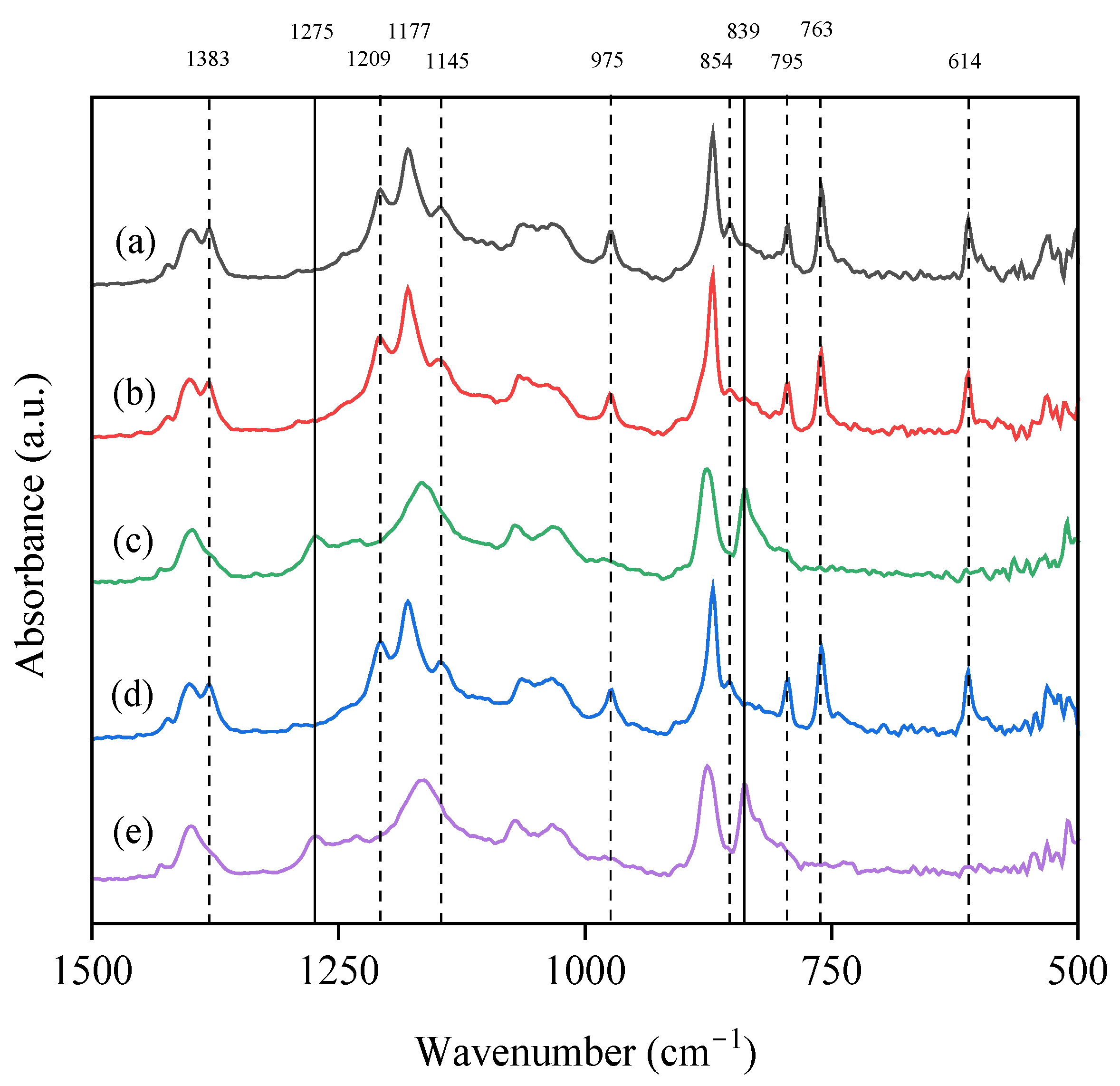
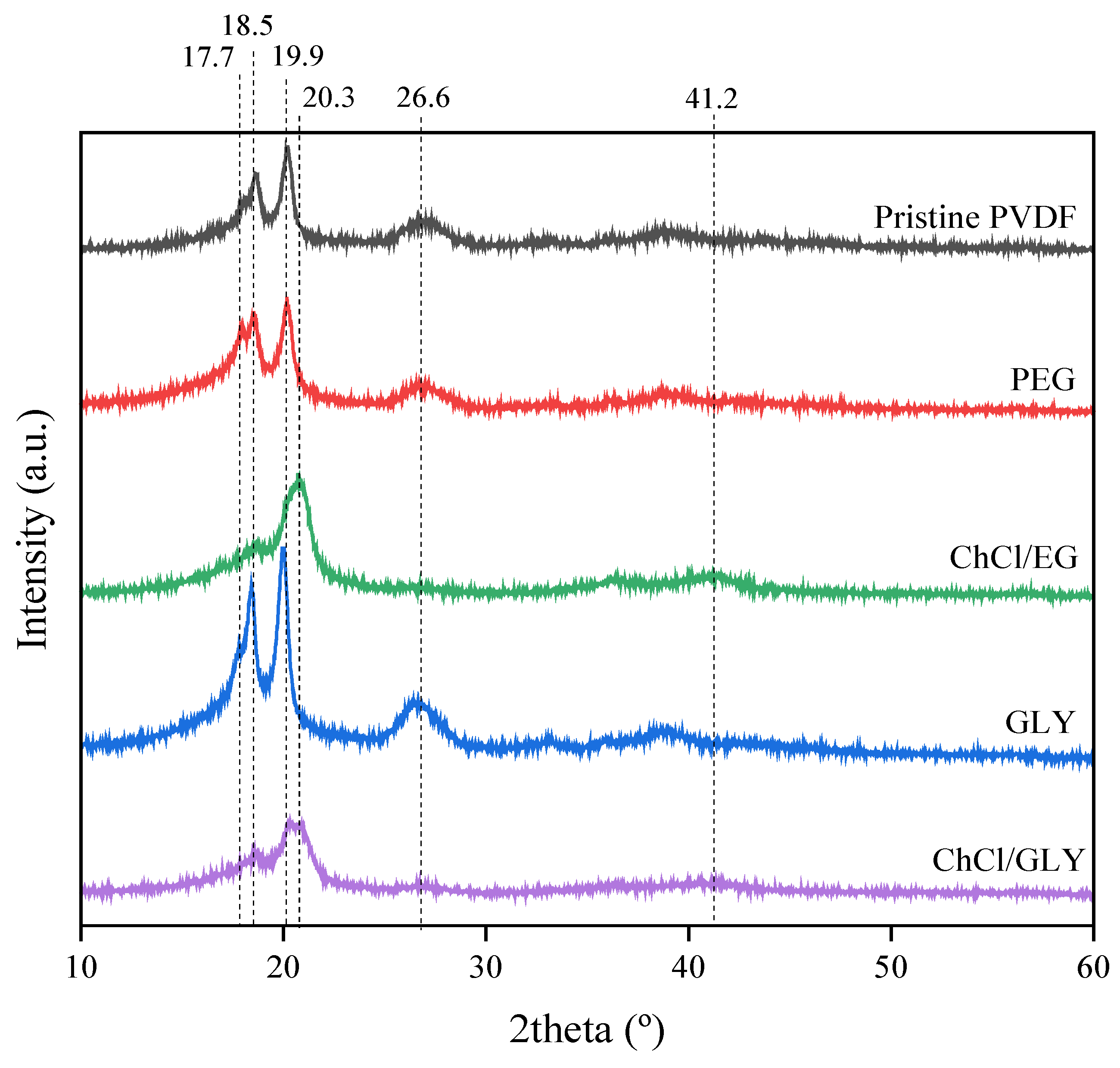
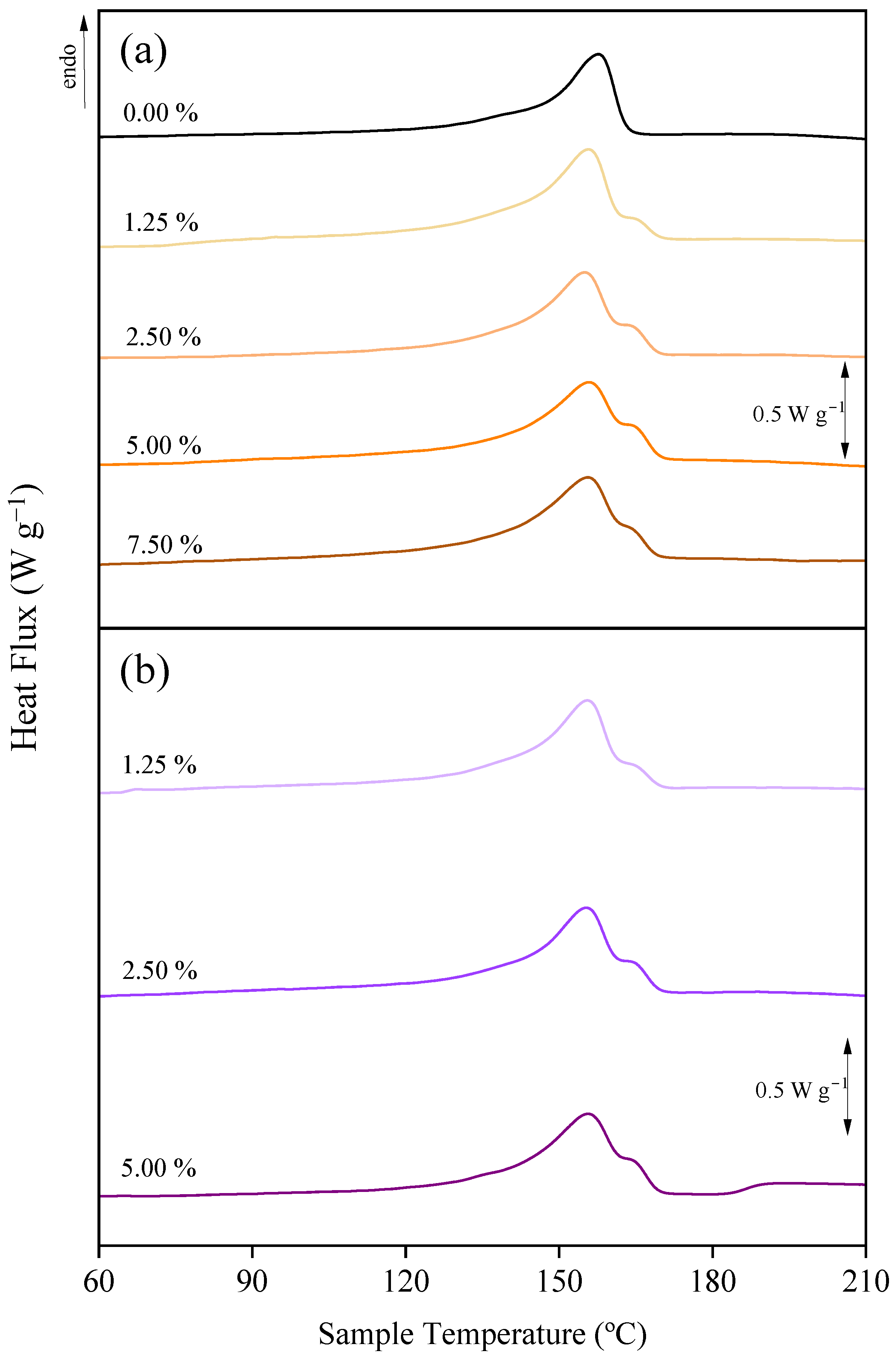
3.3. Effect of Additives on the Chemical Structure and Crystalline Fraction
4. Conclusions
Supplementary Materials
Author Contributions
Funding
Institutional Review Board Statement
Data Availability Statement
Conflicts of Interest
Abbreviations
| (Δh)m: J g−1 | melting enthalpy |
| ChCl | choline chloride |
| ChCl/EG | choline chloride/ethylene glycol (1:2) DES |
| ChCl/GLY | choline chloride/glycerol (1:2) DES |
| DES | deep eutectic solvent |
| DSC | differential scanning calorimetry |
| EG | ethylene glycol |
| FESEM | field emission scanning electron microscopy |
| FTIR | Fourier transform-infrared spectroscopy |
| GLY | glycerol |
| HBA | hydrogen bond acceptor |
| HBD | hydrogen bond donor |
| NIPS | non-solvent induced phase separation |
| OcOH | 1-octanol |
| PEG | poly(ethylene glycol) |
| PVDF | poly(vinylidene fluoride) |
| Dp, µm | pore size distribution |
| Tc, °C | crystallization temperature |
| TEP | triethyl phosphate |
| Tm, °C | melting temperature |
| WCA, ° | water contact angle |
| x | α-crystalline phase |
| X, % | degree of crystallinity |
| XRD | X-ray diffraction |
| y | β-crystalline phase |
References
- United States Environmental Protection Agency. Inventory of U.S. Greenhouse Gas Emissions and Sinks: 1990–2022. U.S. Greenhouse Gas Emissions by Economic Sector, 1990–2022. Available online: https://www.epa.gov/ghgemissions/inventory-us-greenhouse-gas-emissions-and-sinks-1990-2022 (accessed on 8 January 2025).
- Luo, H.; Liu, Z.; Li, Y.; Meng, X.; Yang, X. Characterizing and predicting carbon emissions from an emerging land use perspective: A comprehensive review. Urban Clim. 2024, 58, 102141. [Google Scholar] [CrossRef]
- Han, S.; Li, C.; Li, M.; Lenzen, M.; Chen, X.; Zhang, Y.; Li, M.; Yin, T.; Li, Y.; Li, J.; et al. Prospects for global sustainable development through integrating the environmental impacts of economic activities. Nat. Commun. 2024, 15, 8424. [Google Scholar] [CrossRef] [PubMed]
- Zhang, R.; Liu, R.; Barzagli, F.; Sanku, M.G.; Li, C.; Xiao, M. CO2 absorption in blended amine solvent: Speciation, equilibrium solubility and excessive property. Chem. Eng. J. 2023, 466, 143279. [Google Scholar] [CrossRef]
- Singh, V.K.; Kumar, E.A. Measurement and analysis of adsorption isotherms of CO2 on activated carbon. Appl. Therm. Eng. 2016, 97, 77–86. [Google Scholar] [CrossRef]
- Yousef, A.M.; El-Maghlany, W.M.; Eldrainy, Y.A.; Attia, A. New approach for biogas purification using cryogenic separation and distillation process for CO2 capture. Energy 2018, 156, 328–351. [Google Scholar] [CrossRef]
- Lian, S.; Song, C.; Liu, Q.; Duan, E.; Ren, H.; Kitamura, Y. Recent advances in ionic liquids-based hybrid processes for CO2 capture and utilization. J. Environ. Sci. 2021, 99, 281–295. [Google Scholar] [CrossRef]
- Jiménez-Robles, R.; Martínez-Soria, V.; Izquierdo, M. Fouling characterisation in PVDF membrane contactors for dissolved methane recovery from anaerobic effluents: Effect of surface organofluorosilanisation. Environ. Sci. Pollut. Res. 2023, 30, 29164–29179. [Google Scholar] [CrossRef]
- Jiménez-Robles, R.; Gabaldón, C.; Badia, J.D.; Izquierdo, M.; Martínez-Soria, V. Recovery of dissolved methane through a flat sheet module with PDMS, PP, and PVDF membranes. Sep. Purif. Technol. 2022, 282, 120057. [Google Scholar] [CrossRef]
- Lee, Y.; Park, Y.J.; Lee, J.; Bae, T.H. Recent advances and emerging applications of membrane contactors. Chem. Eng. J. 2023, 461, 141948. [Google Scholar] [CrossRef]
- Imtiaz, A.; Othman, M.H.D.; Jilani, A.; Khan, I.U.; Kamaludin, R.; Ayub, M.; Samuel, O.; Kurniawan, T.A.; Hashim, N.; Puteh, M.H. A critical review in recent progress of hollow fiber membrane contactors for efficient CO2 separations. Chemosphere 2023, 325, 138300. [Google Scholar] [CrossRef]
- Drioli, E.; Giorno, L. Encyclopedia of Membranes; Springer: Berlin/Heidelberg, Germany, 2016. [Google Scholar]
- Wang, D.M.; Lai, J.Y. Recent advances in preparation and morphology control of polymeric membranes formed by nonsolvent induced phase separation. Curr. Opin. Chem. Eng. 2013, 2, 229–237. [Google Scholar] [CrossRef]
- Frommer, M.A.; Messalem, R.M. Mechanism of Membrane Formation. VI. Convective Flows and Large Void Formation During Membrane Precipitation. 1973. Available online: https://pubs.acs.org/sharingguidelines (accessed on 10 January 2025).
- Tao, M.M.; Liu, F.; Ma, B.R.; Xue, L.X. Effect of solvent power on PVDF membrane polymorphism during phase inversion. Desalination 2013, 316, 137–145. [Google Scholar] [CrossRef]
- Figoli, A.; Marino, T.; Simone, S.; Di Nicolò, E.; Li, X.-M.; He, T.; Tornaghi, S.; Drioli, E. Towards non-toxic solvents for membrane preparation: A review. Green Chem. 2014, 16, 4034–4059. [Google Scholar] [CrossRef]
- Xie, W.; Li, T.; Tiraferri, A.; Drioli, E.; Figoli, A.; Crittenden, J.C.; Liu, B. Toward the Next Generation of Sustainable Membranes from Green Chemistry Principles. ACS Sustain. Chem. Eng. 2020, 9, 50–75. [Google Scholar] [CrossRef]
- Mehrabani, S.A.N.; Vatanpour, V.; Koyuncu, I. Green solvents in polymeric membrane fabrication: A review. Sep. Purif. Technol. 2022, 298, 121691. [Google Scholar] [CrossRef]
- Nasrollahi, N.; Ghalamchi, L.; Vatanpour, V.; Khataee, A.; Yousefpoor, M. Novel polymeric additives in the preparation and modification of polymeric membranes: A comprehensive review. J. Ind. Eng. Chem. 2022, 109, 100–124. [Google Scholar] [CrossRef]
- Zeng, H.; Guo, J.; Zhang, Y.; Xing, D.; Yang, F.; Huang, J.; Huang, S.; Shao, L. Green glycerol tailored composite membranes with boosted nanofiltration performance. J. Membr. Sci. 2022, 663, 121064. [Google Scholar] [CrossRef]
- Abednejad, A.S.; Amoabediny, G.; Ghaee, A. Surface modification of polypropylene membrane by polyethylene glycol graft polymerization. Mater. Sci. Eng. C 2014, 42, 443–450. [Google Scholar] [CrossRef]
- Feng, Y.; Han, G.; Chung, T.S.; Weber, M.; Widjojo, N.; Maletzko, C. Effects of polyethylene glycol on membrane formation and properties of hydrophilic sulfonated polyphenylenesulfone (sPPSU) membranes. J. Memb. Sci. 2017, 531, 27–35. [Google Scholar] [CrossRef]
- Zhu, C.; Zhang, X.; Li, F.; Yang, R.; Zhao, X. Effects of Porogen PEG and Pore Structure of PVDF Substrates on the Permeability-Selectivity Trade-off of TFC-NF Membranes. Ind. Eng. Chem. Res. 2023, 62, 8385–8395. [Google Scholar] [CrossRef]
- Lee, J.; Park, B.; Kim, J.; Park, S.B. Effect of PVP, lithium chloride, and glycerol additives on PVDF dual-layer hollow fiber membranes fabricated using simultaneous spinning of TIPS and NIPS. Macromol. Res. 2015, 23, 291–299. [Google Scholar] [CrossRef]
- Lalia, B.S.; Kochkodan, V.; Hashaikeh, R.; Hilal, N. A review on membrane fabrication: Structure, properties and performance relationship. Desalination 2013, 326, 77–95. [Google Scholar] [CrossRef]
- Marco-Velasco, G.; Gálvez-Subiela, A.; Jiménez-Robles, R.; Izquierdo, M.; Cháfer, A.; Badia, J.D. A Review on the Application of Deep Eutectic Solvents in Polymer-Based Membrane Preparation for Environmental Separation Technologies. Polymers 2024, 16, 2604. [Google Scholar] [CrossRef] [PubMed]
- Hansen, B.B.; Spittle, S.; Chen, B.; Poe, D.; Zhang, Y.; Klein, J.M.; Horton, A.; Adhikari, L.; Zelovich, T.; Doherty, B.W.; et al. Deep Eutectic Solvents: A Review of Fundamentals and Applications. Chem. Rev. 2021, 121, 1232–1285. [Google Scholar] [CrossRef]
- Tomé, L.I.N.; Baião, V.; da Silva, W.; Brett, C.M.A. Deep eutectic solvents for the production and application of new materials. Appl. Mater. Today 2018, 10, 30–50. [Google Scholar] [CrossRef]
- El Achkar, T.; Greige-Gerges, H.; Fourmentin, S. Basics and properties of deep eutectic solvents: A review. Environ. Chem. Lett. 2021, 19, 3397–3408. [Google Scholar] [CrossRef]
- NIsmail, N.; Pan, J.; Rahmati, M.; Wang, Q.; Bouyer, D.; Khayet, M.; Cui, Z.; Tavajohi, N. Non-ionic deep eutectic solvents for membrane formation. J. Membr. Sci. 2022, 646, 120238. [Google Scholar] [CrossRef]
- Taghizadeh, M.; Taghizadeh, A.; Vatanpour, V.; Ganjali, M.R.; Saeb, M.R. Deep eutectic solvents in membrane science and technology: Fundamental, preparation, application, and future perspective. Sep. Purif. Technol. 2021, 258, 118015. [Google Scholar] [CrossRef]
- Castro-Muñoz, R.; Galiano, F.; Figoli, A.; Boczkaj, G. Deep eutectic solvents—A new platform in membrane fabrication and membrane-assisted technologies. J. Environ. Chem. Eng. 2022, 10, 106414. [Google Scholar] [CrossRef]
- Kumar, S.A.; Subathra, K.; Srinivasan, G.; Jayaraman, S.; Gnanasekaran, G.; Kanimozhi, G.; Govindaradjane, S. Impact of Tween-80 and Deep Eutectic Solvent-Based Micellar-Enhanced Ultrafiltration in Dairy Wastewater Treatment. Chem. Eng. Technol. 2021, 44, 913–922. [Google Scholar] [CrossRef]
- Chen, L.; Cui, R.; Pan, W.; Dai, J.; Meng, M.; Dai, X.; Pan, J. Role of natural deep eutectic solvents (NADESs) in coagulation bath for PVDF-based membranes on enhanced permeation and separation of rare earth ions. J. Membr. Sci. 2023, 683, 121836. [Google Scholar] [CrossRef]
- Elhamarnah, Y.; Hey, T.; Lipnizki, F.; Qiblawey, H. Investigating the impact of stormwater fouling on polysulfone ultrafiltration membranes modified with deep eutectic solvents. J. Water Process. Eng. 2023, 56, 104362. [Google Scholar] [CrossRef]
- Yeow, A.T.H.; Chan, M.K.; Ong, C.S.; Ho, K.C. Effects of hydrogen bond donors on PVDF membrane modification using choline chloride-based deep eutectic solvents. J. Ind. Eng. Chem. 2024, 139, 514–524. [Google Scholar] [CrossRef]
- Saeed, U.; Khan, A.L.; Mazhar; Gilani, A.; Aslam, M.; Khan, A.U. CO2 separation by supported liquid membranes synthesized with natural deep eutectic solvents. Environ. Sci. Pollut. Res. 2021, 28, 33994–34008. [Google Scholar] [CrossRef]
- Słupek, E.; Makoś, P.; Gȩbicki, J. Theoretical and economic evaluation of low-cost deep eutectic solvents for effective biogas upgrading to bio-methane. Energies 2020, 13, 3379. [Google Scholar] [CrossRef]
- Azzouz, A.; Hayyan, M. Techno-economic feasibility analysis: The missing piece in the puzzle of deep eutectic solvents. Sustain. Mater. Technol. 2024, 39, e00795. [Google Scholar] [CrossRef]
- Vatanpour, V.; Dehqan, A.; Harifi-Mood, A.R. Ethaline deep eutectic solvent as a hydrophilic additive in modification of polyethersulfone membrane for antifouling and separation improvement. J. Membr. Sci. 2020, 614, 118528. [Google Scholar] [CrossRef]
- Saeb, Z.; Bide, Y.; Shokrollahzadeh, S. Structural and separation evaluation of polysulfone-based loose NF membrane modified with itaconic acid-choline chloride deep eutectic solvent as additive. J. Environ. Chem. Eng. 2024, 12, 112046. [Google Scholar] [CrossRef]
- Liu, F.; Hashim, N.A.; Liu, Y.; Abed, M.R.M.; Li, K. Progress in the production and modification of PVDF membranes. J. Membr. Sci. 2011, 375, 1–27. [Google Scholar] [CrossRef]
- Kujawa, J.; Boncel, S.; Al-Gharabli, S.; Koter, S.; Kujawski, W.; Kaneko, K.; Li, K.; Korczeniewski, E.; Terzyk, A.P. Concerted role of PVDF and carbon nanomaterials for membrane science. Desalination 2024, 574, 117277. [Google Scholar] [CrossRef]
- Jiménez-Robles, R.; Izquierdo, M.; Martínez-Soria, V.; Martí, L.; Monleón, A.; Badia, J.D. Stability of Superhydrophobicity and Structure of PVDF Membranes Treated by Vacuum Oxygen Plasma and Organofluorosilanisation. Membranes 2023, 13, 314. [Google Scholar] [CrossRef] [PubMed]
- Jiménez-Robles, R.; Moreno-Torralbo, B.M.; Badia, J.D.; Martínez-Soria, V.; Izquierdo, M. Flat PVDF Membrane with Enhanced Hydrophobicity Through Alkali Activation and Organofluorosilanisation for Dissolved Methane Recovery. Membranes 2022, 12, 426. [Google Scholar] [CrossRef]
- Tan, X.M.; Rodrigue, D. A review on porous polymeric membrane preparation. Part I: Production techniques with polysulfone and poly (vinylidene fluoride). Polymers 2019, 11, 1160. [Google Scholar] [CrossRef]
- Zhang, Z.; Guo, C.; Li, X.; Liu, G.; Lv, J. Effects of PVDF Crystallization on Polymer Gelation Behavior and Membrane Structure from PVDF/TEP System via Modified TIPS Process. Polym. Plast. Technol. Eng. 2013, 52, 564–570. [Google Scholar] [CrossRef]
- HAini, N.; Maggay, I.; Chang, Y.; Venault, A. A Green Stable Antifouling PEGylated PVDF Membrane Prepared by Vapor-Induced Phase Separation. Membranes 2022, 12, 1277. [Google Scholar] [CrossRef]
- Liu, L.; Shen, F.; Chen, X.; Luo, J.; Su, Y.; Wu, H.; Wan, Y. A novel plasma-induced surface hydrophobization strategy for membrane distillation: Etching, dipping and grafting. J. Memb. Sci. 2016, 499, 544–554. [Google Scholar] [CrossRef]
- ASTM F316-03(2019); Test Methods for Pore Size Characteristics of Membrane Filters by Bubble Point and Mean Flow Pore Test. ASTM International: West Conshohocken, PA, USA, 2019. [CrossRef]
- Agarwal, C.; Das, S.; Pandey, A.K. Study on pore size distributions of microporous polymer membranes having different physical architecture using capillary flow porometry. Mater. Today Chem. 2022, 23, 100652. [Google Scholar] [CrossRef]
- Martins, P.; Lopes, A.; Lanceros-Mendez, S. Electroactive phases of poly(vinylidene fluoride): Determination, processing and applications. Prog. Polym. Sci. 2014, 39, 683–706. [Google Scholar] [CrossRef]
- Correia, D.; Ribeiro, C.; Sencadas, V.; Botelho, G.; Carabineiro, S.; Ribelles, J.G.; Lanceros-Méndez, S. Influence of oxygen plasma treatment parameters on poly(vinylidene fluoride) electrospun fiber mats wettability. Prog. Org. Coat. 2015, 85, 151–158. [Google Scholar] [CrossRef]
- Zhang, P.; Tu, Z.; Yan, Z.; Zhang, X.; Hu, X.; Wu, Y. Deep eutectic solvent-based blended membranes for ultra-super selective separation of SO2. J. Hazard. Mater. 2023, 460, 132515. [Google Scholar] [CrossRef]
- Young, T.-H.; Cheng, L.-P.; Lin, D.-J.; Fane, L.; Chuang, W.-Y. Mechanisms of PVDF membrane formation by immersion-precipitation in soft (1-octanol) and harsh (water) nonsolvents. Polymer 1999, 40, 5315–5323. [Google Scholar] [CrossRef]
- Gayatri, R.; Fizal, A.N.S.; Yuliwati, E.; Hossain, S.; Jaafar, J.; Zulkifli, M.; Taweepreda, W.; Yahaya, A.N.A. Preparation and Characterization of PVDF–TiO2 Mixed-Matrix Membrane with PVP and PEG as Pore-Forming Agents for BSA Rejection. Nanomaterials 2023, 13, 1023. [Google Scholar] [CrossRef] [PubMed]
- Zhao, Y.H.; Zhu, B.K.; Ma, X.T.; Xu, Y.Y. Porous membranes modified by hyperbranched polymers. I. Preparation and characterization of PVDF membrane using hyperbranched polyglycerol as additive. J. Membr. Sci. 2007, 290, 222–229. [Google Scholar] [CrossRef]
- Deshmukh, S.P.; Li, K. Effect of ethanol composition in water coagulation bath on morphology of PVDF hollow ®bre membranes. J. Membr. Sci. 1998, 150, 75–85. [Google Scholar] [CrossRef]
- Lin, D.J.; Chang, H.H.; Chen, T.C.; Lee, Y.C.; Cheng, L.P. Formation of porous poly(vinylidene fluoride) membranes with symmetric or asymmetric morphology by immersion precipitation in the water/TEP/PVDF system. Eur. Polym. J. 2006, 42, 1581–1594. [Google Scholar] [CrossRef]
- Jung, J.T.; Kim, J.F.; Wang, H.H.; di Nicolo, E.; Drioli, E.; Lee, Y.M. Understanding the non-solvent induced phase separation (NIPS) effect during the fabrication of microporous PVDF membranes via thermally induced phase separation (TIPS). J. Membr. Sci. 2016, 514, 250–263. [Google Scholar] [CrossRef]
- Fang, Y.; Jiang, B.; Hao, Y.; Yang, N.; Zhang, L.; Zhang, C.; Sun, Y.; Xiao, X.; Zhang, L. Engineering highly permeable thin-film composite nanofiltration membranes by strengthening the diffusion control of amine monomer via deep eutectic solvent. J. Membr. Sci. 2023, 678, 121689. [Google Scholar] [CrossRef]
- Yeow, M.L.; Liu, Y.T.; Li, K. Morphological Study of Poly(vinylidene fluoride) Asymmetric Membranes: Effects of the Solvent, Additive, and Dope Temperature. J. Appl. Polym. Sci. 2004, 92, 1782–1789. [Google Scholar] [CrossRef]
- Kahrs, C.; Schwellenbach, J. Membrane formation via non-solvent induced phase separation using sustainable solvents: A comparative study. Polymer 2020, 186, 122071. [Google Scholar] [CrossRef]
- Shi, L.; Wang, R.; Cao, Y.; Liang, D.T.; Tay, J.H. Effect of additives on the fabrication of poly(vinylidene fluoride-co-hexafluropropylene) (PVDF-HFP) asymmetric microporous hollow fiber membranes. J. Membr. Sci. 2008, 315, 195–204. [Google Scholar] [CrossRef]
- Feng, C.; Wang, R.; Shi, B.; Li, G.; Wu, Y. Factors affecting pore structure and performance of poly(vinylidene fluoride-co-hexafluoro propylene) asymmetric porous membrane. J. Membr. Sci. 2006, 277, 55–64. [Google Scholar] [CrossRef]
- Zhao, C.; Han, Q.; Lin, H.; Guan, J.; Liu, F. Diffusion mediated thermally induced phase separation for preparing poly(vinylidene fluoride) membranes with enhanced separation performances. Sep. Purif. Technol. 2024, 350, 127936. [Google Scholar] [CrossRef]
- Hebbar, R.S.; Isloor, A.M.; Ismail, A.F. Contact Angle Measurements. In Membrane Characterization; Elsevier Inc.: Amsterdam, The Netherlands, 2017; pp. 219–255. [Google Scholar] [CrossRef]
- Chan, M.K.; Ong, C.S.; Kumaran, P. Development and characterization of glycerol coating on the PAN/PVDF composite membranes. IOP Conf. Ser. Mater. Sci. Eng. 2018, 458, 012006. [Google Scholar] [CrossRef]
- Purushothaman, S.M.; Tronco, M.F.; Ponçot, M.; Guigo, N.; Malfois, M.; Kalarikkal, N.; Thomas, S.; Royaud, I.; Rouxel, D. Quantifying the Crystalline Polymorphism in PVDF: Comparative Criteria Using DSC, WAXS, FT-IR, and Raman Spectroscopy. ACS Appl. Polym. Mater. 2024, 6, 8291–8305. [Google Scholar] [CrossRef]
- Cai, X.; Lei, T.; Sun, D.; Lin, L. A critical analysis of the α, β and γ phases in poly(vinylidene fluoride) using FTIR. RSC Adv. 2017, 7, 15382–15389. [Google Scholar] [CrossRef]
- Mohamed, M.A.; Jaafar, J.; Ismail, A.F.; Othman, M.H.D.; Rahman, M.A. Fourier Transform Infrared (FTIR) Spectroscopy. In Membrane Characterization; Elsevier Inc.: Amsterdam, The Netherlands, 2017; pp. 3–29. [Google Scholar] [CrossRef]
- Cui, Z.; Hassankiadeh, N.T.; Zhuang, Y.; Drioli, E.; Lee, Y.M. Crystalline polymorphism in poly(vinylidenefluoride) membranes. Prog. Polym. Sci. 2015, 51, 94–126. [Google Scholar] [CrossRef]
- Chan, K.Y.; Li, C.L.; Wang, D.M.; Lai, J.Y. Formation of Porous Structures and Crystalline Phases in Poly(vinylidene fluoride) Membranes Prepared with Nonsolvent-Induced Phase Separation—Roles of Solvent Polarity. Polymers 2023, 15, 1314. [Google Scholar] [CrossRef]
- Marega, C.; Marigo, A. Influence of annealing and chain defects on the melting behaviour of poly(vinylidene fluoride). Eur. Polym. J. 2003, 39, 1713–1720. [Google Scholar] [CrossRef]


| Additive Conc. | No Additive | PEG * | ChCl/EG * | GLY * | ChCl/GLY * |
|---|---|---|---|---|---|
| 0.00 | 8400 | - | - | - | - |
| 1.25 | - | 8200 | 8200 | 8000 | 8700 |
| 2.50 | - | 8500 | 8400 | 10,000 | 8000 |
| 5.00 | - | 11,000 | 8800 | 12,000 | 8500 |
| 7.50 | - | 13,000 | 10,000 | 20,000 | - |
| 10.00 | - | 12,500 | - | - | - |
| 0.00% | 1.25% | 2.50% | 5.00% | 7.50% | 10.00% | |
|---|---|---|---|---|---|---|
| (a) PEG | ||||||
| Surface | 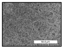 |  | 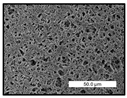 |  |  | 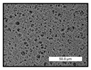 |
| Cross-section | 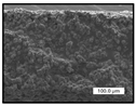 |  |  |  | 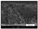 | 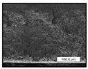 |
| (b) ChCl/EG | ||||||
| Surface | 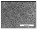 | 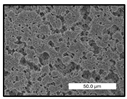 |  | 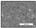 | 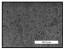 | - |
| Cross-section | 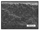 | 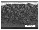 | 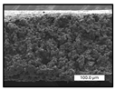 | 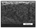 |  | - |
| (c) GLY | ||||||
| Surface |  | 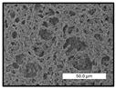 | 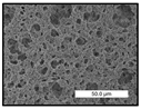 |  | 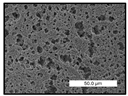 | - |
| Cross-section |  | 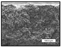 |  |  | 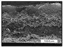 | - |
| (d) ChCl/GLY | ||||||
| Surface |  |  |  | 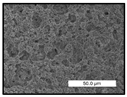 | - | - |
| Cross-section | 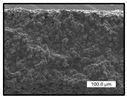 |  |  |  | - | - |
| Additive Conc. | No Additive | PEG * | ChCl/EG * | GLY * | ChCl/GLY * |
|---|---|---|---|---|---|
| Overall porosity (%) | |||||
| 0.00 | 80.4 ± 2.1 | - | - | - | |
| 1.25 | - | 81.4 ± 2.4 | 79.7 ± 2.3 | 82.2 ± 2.0 | 80.4 ± 2.3 |
| 2.50 | - | 74.3 ± 0.5 | 79.1 ± 2.1 | 84.1 ± 1.1 | 74.8 ± 0.6 |
| 5.00 | - | 78.4 ± 0.8 | 75.6 ± 1.1 | 79.7 ± 1.5 | 75.0 ± 0.6 |
| 7.50 | - | 83.4 ± 0.9 | 74.9 ± 0.5 | 82.4 ± 1.6 | - |
| 10.00 | - | 80.6 ± 2.4 | - | - | - |
| Thickness (µm) | |||||
| 0.00 | 294.2 ± 16.5 | - | - | - | |
| 1.25 | - | 304.4 ± 3.2 | 242.7 ± 0.1 | 318.8 ± 15.6 | 262.6 ± 5.3 |
| 2.50 | - | 290.8 ± 9.9 | 248.2 ± 4.1 | 300.6 ± 11.4 | 245.7 ± 7.5 |
| 5.00 | - | 298.6 ± 8.8 | 234.1 ± 3.8 | 305.4 ± 0.1 | 232.7 ± 7.4 |
| 7.50 | - | 295.3 ± 3.9 | 244.1 ±7.4 | 312.8 ±10.3 | - |
| 10.00 | - | 279.7 ± 8.8 | - | - | - |
| Surface density (mg cm−2) | |||||
| 0.00 | 10.2 ± 0.4 | - | - | - | - |
| 1.25 | - | 10.6 ± 0.5 | 10.1 ± 0.7 | 10.2 ± 0.3 | 10.2 ± 0.7 |
| 2.50 | - | 10.1 ± 0.1 | 10.9 ± 0.4 | 10.1 ± 0.3 | 10.0 ± 0.2 |
| 5.00 | - | 10.8 ± 0.6 | 10.4 ± 0.7 | 10.5 ± 0.6 | 10.9 ± 0.5 |
| 7.50 | - | 10.8 ± 0.1 | 10.3 ± 0.2 | 10.7 ± 0.3 | - |
| 10.00 | - | 10.0 ± 0.1 | - | - | - |
| Most probable pore size, Dp (µm) | |||||
| 0.00 | 3.30 b | - | - | - | - |
| 1.25 | - | 0.77 a | 3.85 b | 2.31 b | 2.10 b |
| 2.50 | - | 0.66 a | 5.78 c | 3.85 b | 2.72 b |
| 5.00 | - | 0.77 a | 5.78 c | 3.55 b | >d.l. |
| 7.50 | - | 0.77 a | >d.l. | 2.01 b | - |
| 10.00 | - | 0.71 a | - | - | - |
| Additive Conc. | No Additive | PEG * | ChCl/EG * | GLY * | ChCl/GLY * |
|---|---|---|---|---|---|
| 0.00 | 143.9 ± 2.2 | - | - | - | - |
| 1.25 | - | 128.2 ± 4.2 | 130.9 ± 4.8 | 133.5 ± 5.6 | 138.9 ± 4.1 |
| 2.50 | - | 130.3 ± 4.3 | 145.4 ± 2.0 | 132.0 ± 4.1 | 135.1 ± 3.1 |
| 5.00 | - | 129.1 ± 1.9 | 145.7 ± 1.6 | 136.0 ± 2.7 | 146.8 ± 2.8 |
| 7.50 | - | 118.9 ± 2.0 | 127.3 ± 4.1 | 101.8 ± 5.3 | - |
| 10.00 | - | 118.1 ± 5.7 | - | - | - |
| Additive Conc. | No Additive | PEG * | ChCl/EG * | GLY * | ChCl/GLY * |
|---|---|---|---|---|---|
| (a) α-crystalline phase (%) | |||||
| 0.00 | 75.0 | - | - | - | - |
| 1.25 | - | 75.4 | 48.0 | 76.5 | 44.0 |
| 2.50 | - | 75.6 | 24.3 | 74.8 | 39.2 |
| 5.00 | - | 72.8 | 19.2 | 76.1 | 18.2 |
| 7.50 | - | 73.4 | 18.1 | 77.2 | - |
| 10.00 | - | 72.6 | - | - | - |
| (b) Crystallinity degree (%) | |||||
| 0.00 | 53.1 | - | - | - | - |
| 1.25 | - | 51.7 | 53.7 | 56.0 | 55.5 |
| 2.50 | - | 54.2 | 51.1 | 51.7 | 51.6 |
| 5.00 | - | 47.5 | 51.3 | 51.6 | 50.8 |
| 7.50 | - | 47.1 | 49.7 | 54.4 | - |
| 10.00 | - | 50.5 | - | - | - |
Disclaimer/Publisher’s Note: The statements, opinions and data contained in all publications are solely those of the individual author(s) and contributor(s) and not of MDPI and/or the editor(s). MDPI and/or the editor(s) disclaim responsibility for any injury to people or property resulting from any ideas, methods, instructions or products referred to in the content. |
© 2025 by the authors. Licensee MDPI, Basel, Switzerland. This article is an open access article distributed under the terms and conditions of the Creative Commons Attribution (CC BY) license (https://creativecommons.org/licenses/by/4.0/).
Share and Cite
Gálvez-Subiela, A.; Jiménez-Robles, R.; Badia-Valiente, J.D.; Izquierdo, M.; Chafer, A. Effect of Choline Chloride-Based DES on the Pore-Forming Ability and Properties of PVDF Membranes Prepared with Triethyl Phosphate as Green Solvent. Polymers 2025, 17, 984. https://doi.org/10.3390/polym17070984
Gálvez-Subiela A, Jiménez-Robles R, Badia-Valiente JD, Izquierdo M, Chafer A. Effect of Choline Chloride-Based DES on the Pore-Forming Ability and Properties of PVDF Membranes Prepared with Triethyl Phosphate as Green Solvent. Polymers. 2025; 17(7):984. https://doi.org/10.3390/polym17070984
Chicago/Turabian StyleGálvez-Subiela, Alejandro, Ramón Jiménez-Robles, Jose David Badia-Valiente, Marta Izquierdo, and Amparo Chafer. 2025. "Effect of Choline Chloride-Based DES on the Pore-Forming Ability and Properties of PVDF Membranes Prepared with Triethyl Phosphate as Green Solvent" Polymers 17, no. 7: 984. https://doi.org/10.3390/polym17070984
APA StyleGálvez-Subiela, A., Jiménez-Robles, R., Badia-Valiente, J. D., Izquierdo, M., & Chafer, A. (2025). Effect of Choline Chloride-Based DES on the Pore-Forming Ability and Properties of PVDF Membranes Prepared with Triethyl Phosphate as Green Solvent. Polymers, 17(7), 984. https://doi.org/10.3390/polym17070984