
Background of New Measurement Electronic Devices with Polyelectrolyte Hydrogel Base

 , , ,
, , , 
Abstract
1. Introduction
2. Material
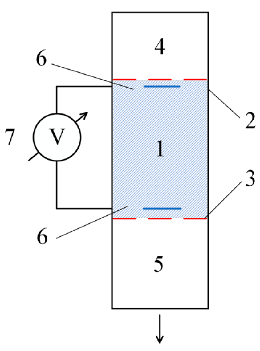
3. Experiments
- A tube filled with hydrogel (1);
- Membranes (2) and (3), which separate the working material from the low-molecular-weight salt solutions used;
- A volume (4) filled with a low-molecular-weight salt solution;
- A buffer volume (5), which collects the low-molecular-weight salt that has passed through the hydrogel layer;
- Electrodes (6), intended for measuring the dynamic potential difference;
- A precision voltmeter (7), allowing measurements on the order of millivolts.
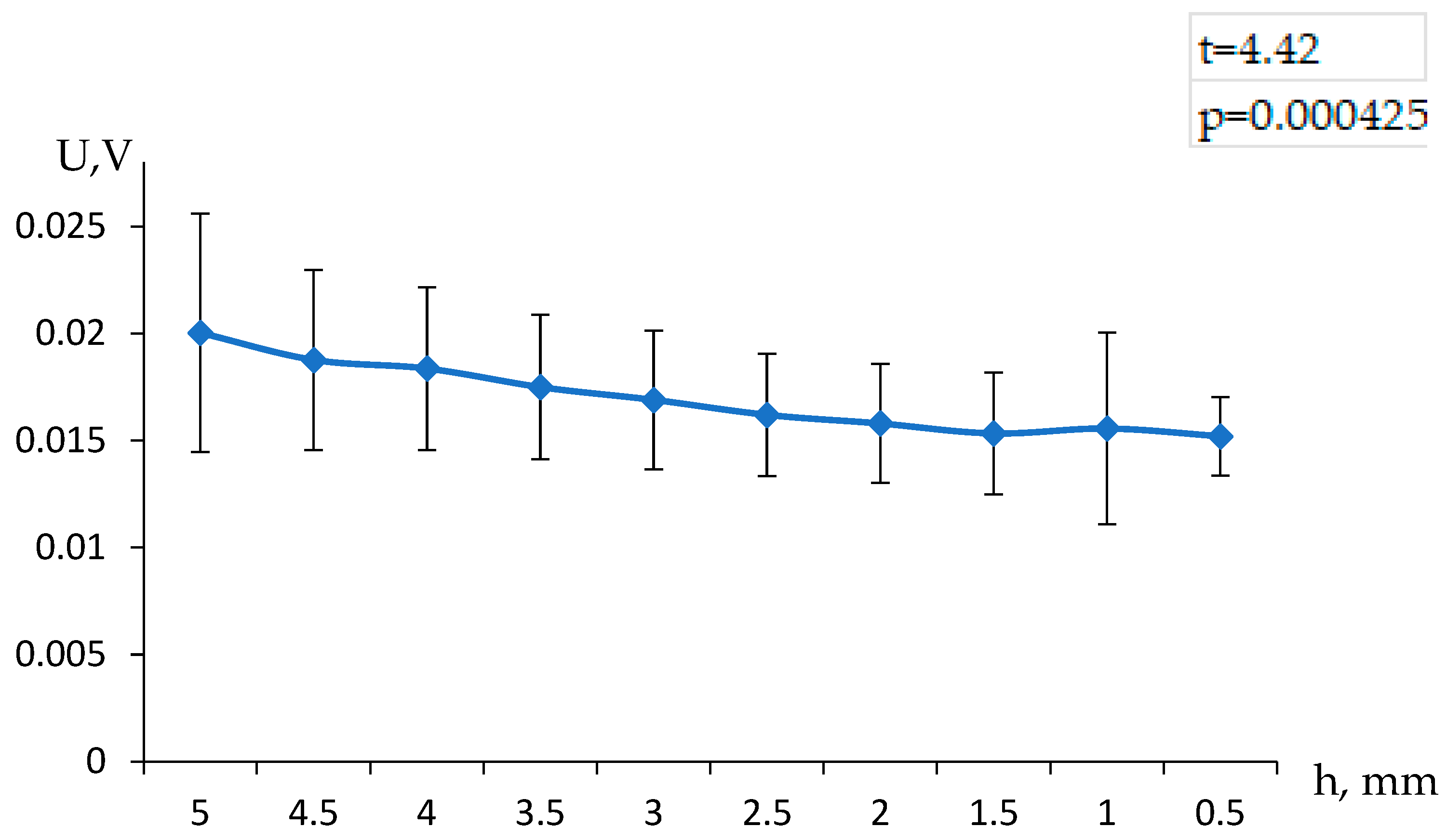
4. Results
5. Analysis
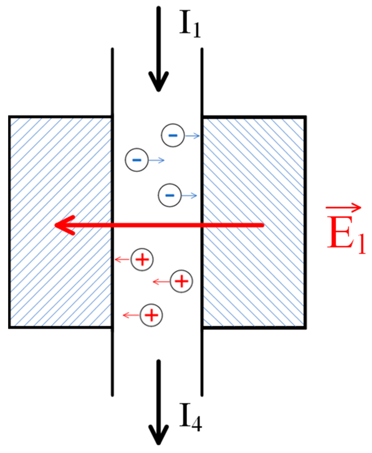
5.1. Qualitative Consideration of EMF Formation During the Flow of a Low-Molecular-Weight Salt Solution Through a Polyelectrolyte Hydrogel
- -
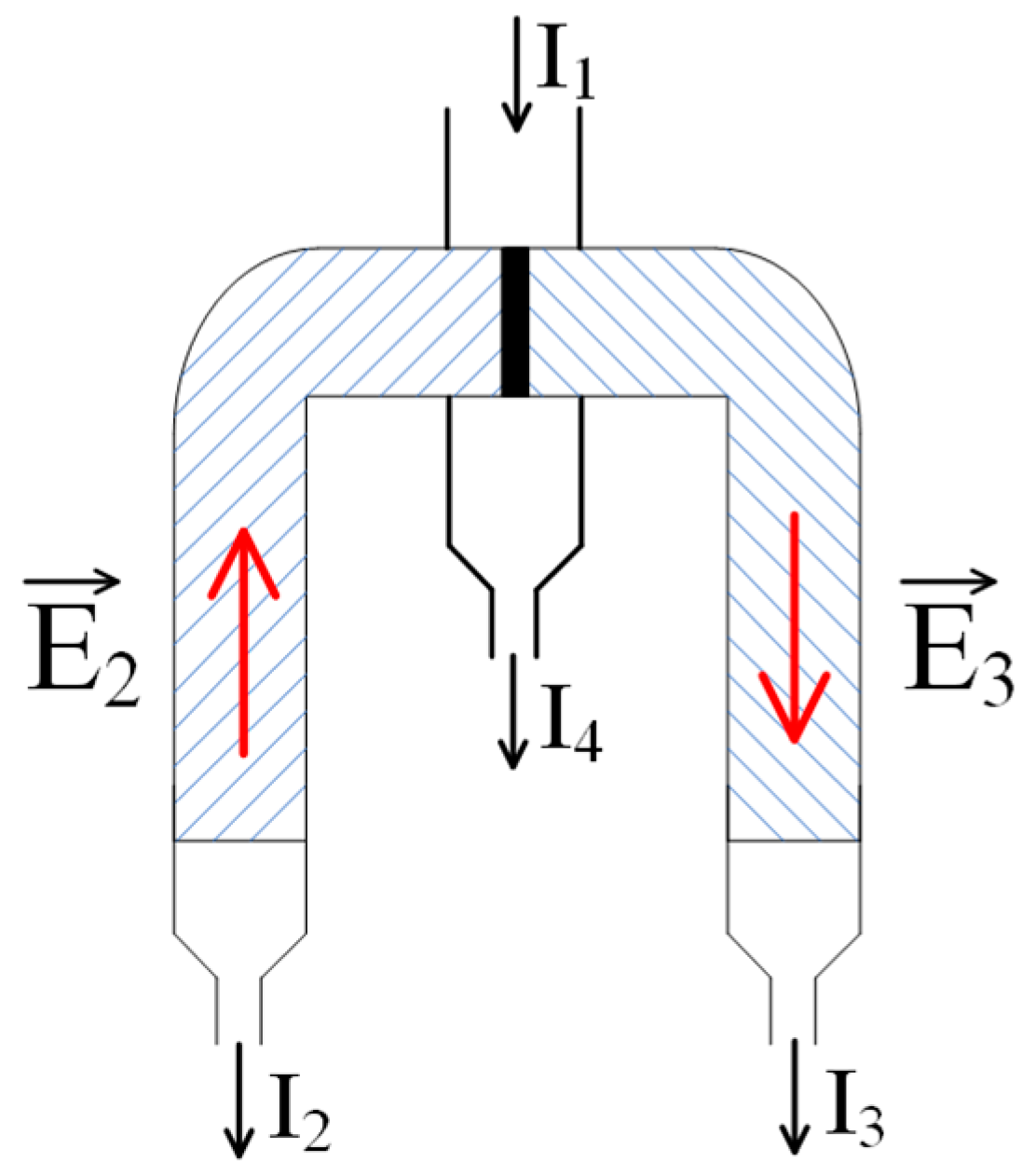
- An outlet (1) through which the feed solution enters the system;
- -
- A column (2) filled with a gel, the mesh of which carries a negative electrical charge;
- -
- A column (3) filled with a gel whose mesh carries a positive electrical charge;
- -
- Outlets for the depleted (4) and enriched (5) solutions;
- -
- An auxiliary connecting elements (6) and (7).
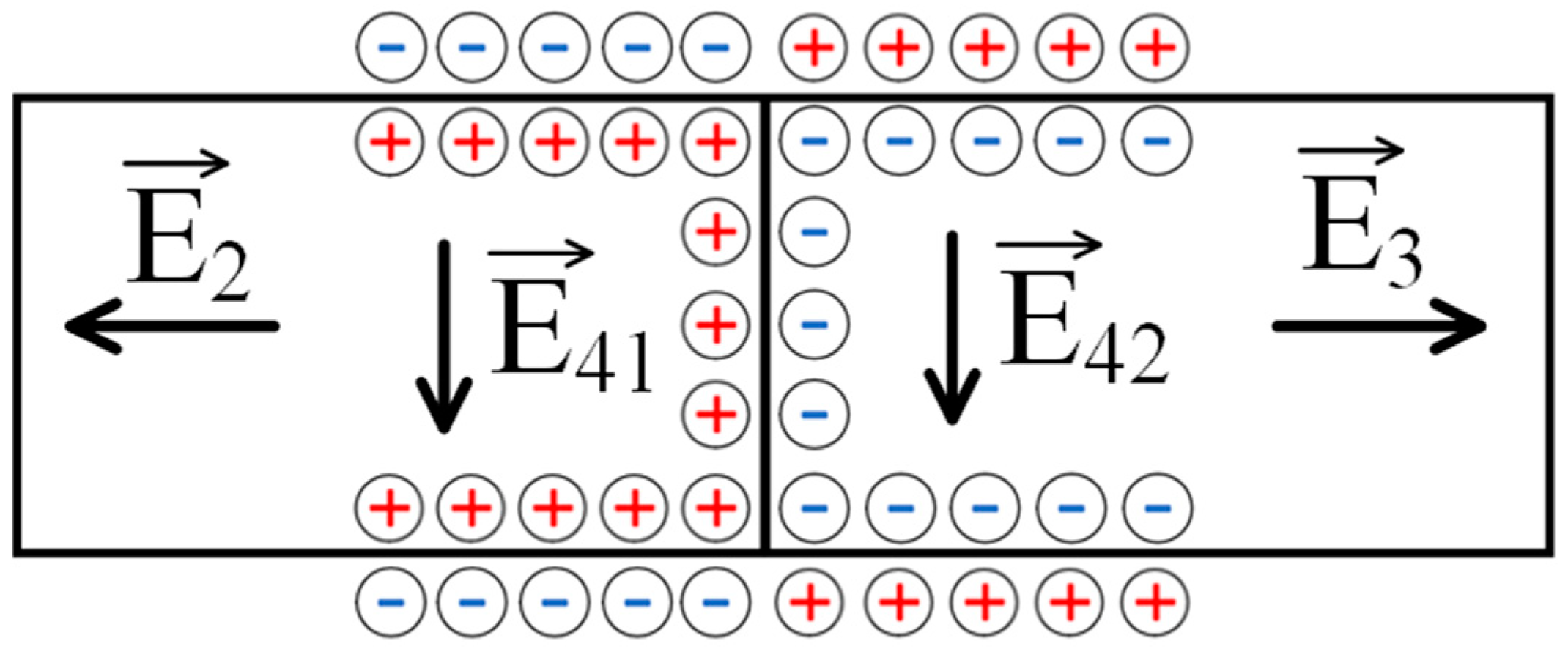
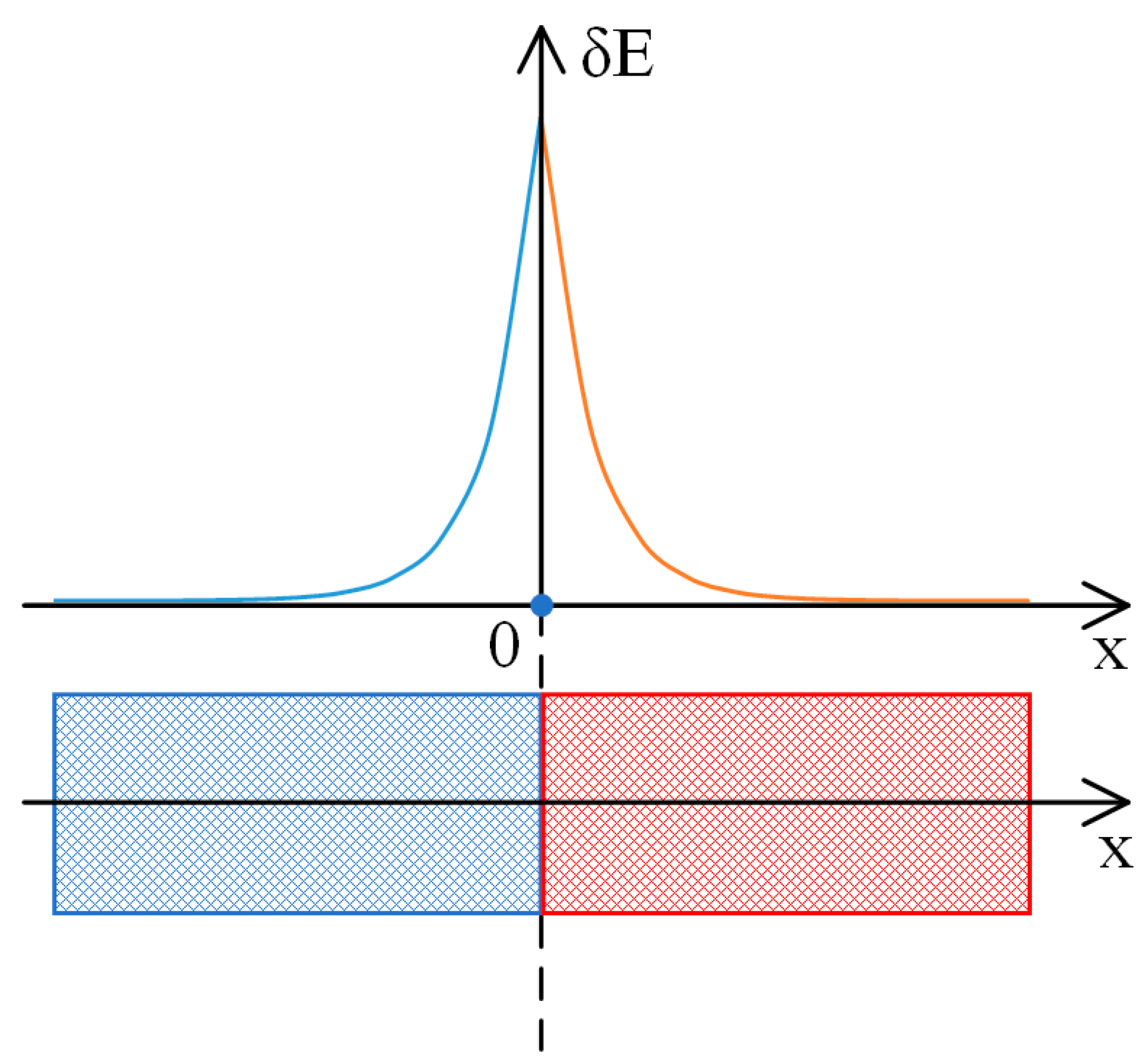
5.2. EMF Formation During Salt Solution Flows Through a Polyelectrolyte Network
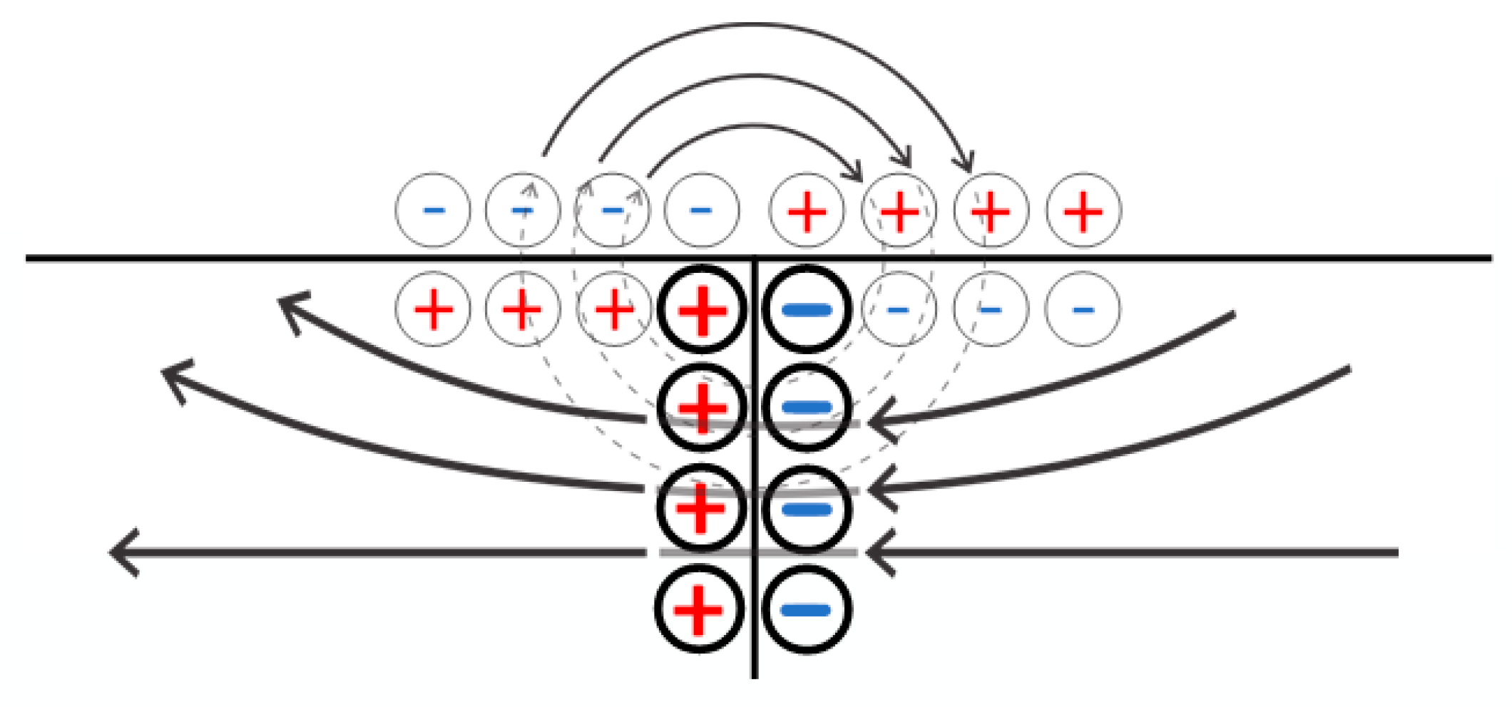
5.3. Separation of Solution Streams into Enriched and Depleted by the Contact of Oppositely Charged Meshes
6. Discussions
7. Conclusions
Author Contributions
Funding
Institutional Review Board Statement
Data Availability Statement
Conflicts of Interest
References
- Boborodea, A.G.; Clemens, M.; Daoust, D.; Bailly, C. Gel permeation chromatography calibration based on fractal geometry. J. Appl. Polym. Sci. 2004, 93, 771–777. [Google Scholar] [CrossRef]
- Ejima, D.; Yumioka, R.; Arakawa, T.; Tsumoto, K. Arginine as an effective additive in gel permeation chromatography. J. Chromatogr. A 2005, 1094, 49–55. [Google Scholar] [CrossRef] [PubMed]
- Zhou, T.; Yuk, H.; Hu, F.; Wu, J.; Tian, F.; Roh, H.; Shen, Z.; Gu, G.; Xu, J.; Lu, B.; et al. 3D printable high-performance conducting polymer hydrogel for all-hydrogel bioelectronic interfaces. Nat. Mater. 2023, 22, 895–902. [Google Scholar] [CrossRef] [PubMed]
- Han, W.B.; Ko, G.-J.; Jang, T.-M.; Hwang, S.-W. Materials, Devices, and Applications for Wearable and Implantable Electronics. ACS Appl. Electron. Mater. 2021, 3, 485–503. [Google Scholar] [CrossRef]
- Rasool, A.; Qureshi, M.A.u.R.; Islam, A.; Fayyaz, S. Hydrogels and Their Emerging Applications. In Hydrogels; CRC Press: Boca Raton, FL, USA, 2023; pp. 103–126. [Google Scholar]
- Laftah, W.A.; Hashim, S.; Ibrahim, A.N. Polymer Hydrogels: A Review. Polym. Plast. Technol. Eng. 2011, 50, 1475–1486. [Google Scholar] [CrossRef]
- Nakan, U.; Mun, G.A.; Rakhmetullayeva, R.K.; Tolkyn, B.; Bieerkehazhi, S.; Yeligbayeva, G.Z.; Negim, E. Thermosensitive N-isopropylacrylamide-CO-2-hydroxyethyl acrylate hydrogels interactions with poly(acrylic acid) and surfactants. Polym. Adv. Technol. 2021, 32, 2676–2681. [Google Scholar] [CrossRef]
- Suleimenov, I.E.; Guven, O.; Mun, G.A.; Uzun, C.; Gabrielyan, O.A.; Kabdushev, S.B.; Agibaeva, L.; Nurtazin, A. Hysteresis effects during the phase transition in solutions of temperature sensitive polymers. Eurasian Chem. J. 2017, 19, 41–46. [Google Scholar] [CrossRef]
- Mercer, S.M.; Jessop, P.G. “Switchable Water”: Aqueous Solutions of Switchable Ionic Strength. ChemSusChem 2010, 3, 467–470. [Google Scholar] [CrossRef] [PubMed]
- Seo, J.Y.; Lee, B.; Kang, T.W.; Noh, J.H.; Kim, M.J.; Ji, Y.B.; Ju, H.J.; Min, B.H.; Kim, M.S. Electrostatically Interactive Injectable Hydrogels for Drug Delivery. Tissue Eng. Regen. Med. 2018, 15, 513–520. [Google Scholar] [CrossRef]
- Hu, J.; Zhang, G.; Liu, S. Enzyme-responsive polymeric assemblies, nanoparticles and hydrogels. Chem. Soc. Rev. 2012, 41, 5933. [Google Scholar] [CrossRef] [PubMed]
- Mun, S.; Kim, Y.-R.; McClements, D.J. Control of β-carotene bioaccessibility using starch-based filled hydrogels. Food Chem. 2015, 173, 454–461. [Google Scholar] [CrossRef] [PubMed]
- Budtova, T.; Suleimenov, I.; Frenkel, S. Peculiarities of the kinetics of polyelectrolyte hydrogel collapse in solutions of copper sulfate. Polymer 1995, 36, 2055–2058. [Google Scholar] [CrossRef]
- Budtova, T.; Suleimenov, I. Swelling behaviour of a polyelectrolyte network under load. Polymer 1997, 38, 5947–5952. [Google Scholar] [CrossRef]
- Appel, E.A.; del Barrio, J.; Loh, X.J.; Scherman, O.A. Supramolecular polymeric hydrogels. Chem. Soc. Rev. 2012, 41, 6195. [Google Scholar] [CrossRef] [PubMed]
- Shi, Z.; Gao, X.; Ullah, M.W.; Li, S.; Wang, Q.; Yang, G. Electroconductive natural polymer-based hydrogels. Biomaterials 2016, 111, 40–54. [Google Scholar] [CrossRef] [PubMed]
- Budtova, T.; Suleimenov, I.; Frenkel, S. Electrokinetics of the contraction of a polyelectrolyte hydrogel under the influence of constant electric current. Polym. Gels Netw. 1995, 3, 387–393. [Google Scholar] [CrossRef]
- Yang, C.; Suo, Z. Hydrogel ionotronics. Nat. Rev. Mater. 2018, 3, 125–142. [Google Scholar] [CrossRef]
- Yuk, H.; Lu, B.; Zhao, X. Hydrogel bioelectronics. Chem. Soc. Rev. 2019, 48, 1642–1667. [Google Scholar] [CrossRef] [PubMed]
- Budtova, T.; Suleimenov, I.E.; Frenkel’, S.Y. A diffusion approach to description of swelling of polyelectrolyte hydrogels. Polym. Sci. 1995, 37, 10–16. [Google Scholar]
- Hua, X.; Nian-Yi, C. The Research of Donnan Equilibrium with Hypeinetted-chain(HNC) Approximation Method. Acta Physico-Chim. Sin. 1996, 12, 320–324. [Google Scholar] [CrossRef]
- Budtova, T.; Suleimenov, I. Physical principles of using polyelectrolyte hydrogels for purifying and enrichment technologies. J. Appl. Polym. Sci. 1995, 57, 1653–1658. [Google Scholar] [CrossRef]
- Suleimenov, I.E.; Mun, G.A.; Pak, I.T.; Kabdushev, S.B.; Kenessova, Z.A.; Kopishev, E.E. Redistribution of the concentrations in polyelectrolyte hydrogels contacts as the basis of new desalination technologies. News Natl. Acad. Sci. Repub. Kazakhstan Ser. Geol. Tech. Sci. 2017, 3, 198–205. [Google Scholar]
- Pastukhov, A.V.; Davankov, V.A.; Tsyurupa, M.P.; Blinnikova, Z.K.; Kavalerskaya, N.E. The contraction of granules of nanoporous super-cross-linked polystyrene sorbents as a result of the exclusion of large-sized mineral electrolyte ions from the polymer phase. Russ. J. Phys. Chem. A 2009, 83, 457–464. [Google Scholar] [CrossRef]
- Agapov, I.O.; Ferapontov, N.B.; Tokmachev, M.G.; Trobov, K.T.; Gagarin, A.N. Phase Properties of Polymer Gels and Influence of the Composition of the External Solution. Moscow Univ. Chem. Bull. 2019, 74, 209–215. [Google Scholar] [CrossRef]
- Le, N.L.; Nunes, S.P. Materials and membrane technologies for water and energy sustainability. Sustain. Mater. Technol. 2016, 7, 1–28. [Google Scholar] [CrossRef]
- Brunetti, A.; Scura, F.; Barbieri, G.; Drioli, E. Membrane technologies for CO2 separation. J. Memb. Sci. 2010, 359, 115–125. [Google Scholar] [CrossRef]
- Marek, J.; Čížek, J.; Tvrzník, D. Optimizing porous material in shock electrodialysis unit. Desalin. Water Treat. 2019, 170, 38–45. [Google Scholar] [CrossRef]
- Wang, Y.; Fang, M.; Huang, Y.; Wang, T.; Li, S.; Lu, X.; Xie, Y. Removal of heat stable salts from degraded amine solvent by “BMED+ED” two-stage electrodialysis unit. Int. J. Greenh. Gas Control 2023, 127, 103939. [Google Scholar] [CrossRef]
- Toktabayeva, A.; Rakhmetullayeva, R.; Abutalip, M.; Mamutova, A.; Batyrbayeva, A.; Mun, G. The new hybrid copolymers based on N-isopropylacrylamide. J. Chem. Technol. Metall. 2019, 54, 475–482. [Google Scholar]
- Balaj, R.V.; Cho, S.W.; Singh, P.; Zarzar, L.D. Polyelectrolyte hydrogel capsules as stabilizers for reconfigurable complex emulsions. Polym. Chem. 2020, 11, 281–286. [Google Scholar] [CrossRef]
- Hoang, H.T.; Jo, S.H.; Phan, Q.T.; Park, H.; Park, S.H.; Oh, C.W.; Lim, K.T. Dual pH-/thermo-responsive chitosan-based hydrogels prepared using “click” chemistry for colon-targeted drug delivery applications. Carbohydr. Polym. 2021, 260, 117812. [Google Scholar] [CrossRef]
- Jabbari, E.; Nozari, S. Swelling behavior of acrylic acid hydrogels prepared by γ-radiation crosslinking of polyacrylic acid in aqueous solution. Eur. Polym. J. 2000, 36, 2685–2692. [Google Scholar] [CrossRef]
- Harrison, I.P.; Spada, F. Hydrogels for atopic dermatitis and wound management: A superior drug delivery vehicle. Pharmaceutics 2018, 10, 71. [Google Scholar] [CrossRef] [PubMed]
- Koev, T.T.; Harris, H.C.; Kiamehr, S.; Khimyak, Y.Z.; Warren, F.J. Starch hydrogels as targeted colonic drug delivery vehicles. Carbohydr. Polym. 2022, 289, 119413. [Google Scholar] [CrossRef] [PubMed]
- Tavakoli, J.; Tang, Y. Hydrogel based sensors for biomedical applications: An updated review. Polymers 2017, 9, 364. [Google Scholar] [CrossRef] [PubMed]
- Sun, X.; Ding, C.; Qin, M.; Li, J. Hydrogel-Based Biosensors for Bacterial Infections. Small 2024, 20, 2306960. [Google Scholar] [CrossRef] [PubMed]
- Andrade, F.; Roca-Melendres, M.M.; Durán-Lara, E.F.; Rafael, D.; Schwartz, S. Review stimuli-responsive hydrogels for cancer treatment: The role of ph, light, ionic strength and magnetic field. Cancers 2021, 13, 1164. [Google Scholar] [CrossRef] [PubMed]
- Roshan Deen, G.; Loh, X.J. Stimuli-responsive cationic hydrogels in drug delivery applications. Gels 2018, 4, 13. [Google Scholar] [CrossRef]
- Hu, L.; Chee, P.L.; Sugiarto, S.; Yu, Y.; Shi, C.; Yan, R.; Yao, Z.; Shi, X.; Zhi, J.; Kai, D.; et al. Hydrogel-Based Flexible Electronics. Adv. Mater. 2023, 35, 2205326. [Google Scholar] [CrossRef] [PubMed]
- Zhang, Y.; Tan, Y.; Lao, J.; Gao, H.; Yu, J. Hydrogels for Flexible Electronics. ACS Nano 2023, 17, 9681–9693. [Google Scholar] [CrossRef]
- Babiak, P.; Schaffer-Harris, G.; Kainuma, M.; Fedorovich, V.; Goryanin, I. Development of a New Hydrogel Anion Exchange Membrane for Swine Wastewater Treatment. Membranes 2022, 12, 984. [Google Scholar] [CrossRef]
- Ramírez-Carmona, M.; Gálvez-Gómez, M.P.; González-Perez, L.; Pinedo-Rangel, V.; Pineda-Vasquez, T.; Hotza, D. Production of Bacterial Cellulose Hydrogel and its Evaluation as a Proton Exchange Membrane. J. Polym. Environ. 2023, 31, 2462–2472. [Google Scholar] [CrossRef]
- Olthuis, W.; Schippers, B.; Eijkel, J.; van den Berg, A. Energy from streaming current and potential. Sens. Actuators B Chem. 2005, 111–112, 385–389. [Google Scholar] [CrossRef]
- Hsu, W.L.; Daiguji, H.; Dunstan, D.E.; Davidson, M.R.; Harvie, D.J.E. Electrokinetics of the silica and aqueous electrolyte solution interface: Viscoelectric effects. Adv. Colloid Interface Sci. 2016, 234, 108–131. [Google Scholar] [CrossRef] [PubMed]
- Pourjavadi, A.; Doulabi, M.; Doroudian, M. Adsorption characteristics of malachite green dye onto novel kappa-carrageenan-g-polyacrylic acid/TiO2-NH2 hydrogel nanocomposite. J. Iran. Chem. Soc. 2014, 11, 1057–1065. [Google Scholar] [CrossRef]
- Lian, E.; Shi, R.; Deng, Y.; Zhu, H.; Ma, Y. Adsorption of low cross-linking density hydrogel OMMT/acid hydrolysis lignin grafted polyacrylic acid for Cd (II). AIP Conf. Proc. 2017, 1820, 020001. [Google Scholar]
- Budtova, T.; Belnikevich, N.; Suleimenov, I.; Frenkel, S.Y. Concentration redistribution of low-molecular-weight salts of metals in the presence of a strongly swelling polyelectrolyte hydrogel. Polymer 1993, 34, 5154–5156. [Google Scholar] [CrossRef]
- Malchesky, P.S.; Surovy, R.M.; Nose, Y. The charcoal coil: A dialysis dialysate regeneration system. Kidney Int. 1976, 10, 296–299. [Google Scholar]
- Klinkmann, H.; Vienken, J. Nephrology Dialysis Transplantation Membranes for dialysis. Nephrol. Dial. Transplant. 1995, 10, 39–45. [Google Scholar] [CrossRef] [PubMed]
- Kim, M.K.; Park, Y.; Kim, I.J.; Lee, J.S. Emerging Materials for Neuromorphic Devices and Systems. iScience 2020, 23, 101846. [Google Scholar] [CrossRef] [PubMed]
- Zhu, Q.B.; Li, B.; Yang, D.D.; Liu, C.; Feng, S.; Chen, M.L.; Sun, Y.; Tian, Y.N.; Su, X.; Wang, X.M.; et al. A flexible ultrasensitive optoelectronic sensor array for neuromorphic vision systems. Nat. Commun. 2021, 12, 1798. [Google Scholar] [CrossRef] [PubMed]
- Lee, H.R.; Won, Y.; Oh, J.H. Neuromorphic bioelectronics based on semiconducting polymers. J. Polym. Sci. 2022, 60, 348–376. [Google Scholar] [CrossRef]
- Kesler, V.; Murmann, B.; Soh, H.T. Going beyond the Debye Length: Overcoming Charge Screening Limitations in Next-Generation Bioelectronic Sensors. ACS Nano 2020, 14, 16194–16201. [Google Scholar] [CrossRef]
- Blossey, R. The Poisson-Boltzmann Equation; SpringerBriefs in Physics; Springer: Cham, Switzerland, 2023; Volume F1037, pp. 1–25. [Google Scholar]
- Doi, M. Onsager’s variational principle in soft matter. J. Phys. Condens. Matter 2011, 23, 284118. [Google Scholar] [CrossRef] [PubMed]
- Lin, L.S.; Yasuda, K.; Ishimoto, K.; Hosaka, Y.; Komura, S. Onsager’s Variational Principle for Nonreciprocal Systems with Odd Elasticity. J. Phys. Soc. Jpn. 2023, 92, 033001. [Google Scholar] [CrossRef]
- Sharfarets, B.P.; Dmitriev, S.P.; Kurochkin, V.E.; Legusha, F.F. Acoustoelectric transducer based on electrokinetic phenomenon flow potential. Tech. Phys. Lett. 2022, 48, 65. [Google Scholar] [CrossRef]
- Santoso, P.H.; Kurniawan, Y.; Pamungkas, H.N.; Suparno, S. Karakterisasi Muatan Nanopartikel Silika (SiO2) dengan Metode Elektroforesis. Indones. J. Appl. Phys. 2021, 11, 1. [Google Scholar] [CrossRef]
- Wirthl, D.; Pichler, R.; Drack, M.; Kettlguber, G.; Moser, R.; Gerstmayr, R.; Hartmann, F.; Bradt, E.; Kaltseis, R.; Siket, C.M.; et al. Instant tough bonding of hydrogels for soft machines and electronics. Sci. Adv. 2017, 3, e1700053. [Google Scholar] [CrossRef]
- Lewns, F.K.; Tsigkou, O.; Cox, L.R.; Wildman, R.D.; Grover, L.M.; Poologasundarampillai, G. Hydrogels and Bioprinting in Bone Tissue Engineering: Creating Artificial Stem-Cell Niches for In Vitro Models. Adv. Mater. 2023, 35, e2301670. [Google Scholar] [CrossRef] [PubMed]
- De Piano, R.; Caccavo, D.; Barba, A.A.; Lamberti, G. Polyelectrolyte hydrogels in biological systems: Modeling of swelling and deswelling behavior. Chem. Eng. Sci. 2023, 279, 118959. [Google Scholar] [CrossRef]
- Raeke, J.; Lechtenfeld, O.J.; Wagner, M.; Herzsprung, P.; Reemtsma, T. Selectivity of solid phase extraction of freshwater dissolved organic matter and its effect on ultrahigh resolution mass spectra. Environ. Sci. Process. Impacts 2016, 18, 918–927. [Google Scholar] [CrossRef] [PubMed]
- Zhang, L.; Fu, L.; Zhang, X.; Chen, L.; Cai, Q.; Yang, X. Hierarchical and heterogeneous hydrogel system as a promising strategy for diversified interfacial tissue regeneration. Biomater. Sci. 2021, 9, 1547–1573. [Google Scholar] [CrossRef]
- Jin, L.; Xu, J.; Xue, Y.; Zhang, X.; Feng, M.; Wang, C.; Yao, W.; Wang, J.; He, M. Research progress in the multilayer hydrogels. Gels 2021, 7, 172. [Google Scholar] [CrossRef] [PubMed]
- Zhang, M.; Yang, Y.; Li, M.; Shang, Q.; Xie, R.; Yu, J.; Shen, K.; Zhang, Y.; Cheng, Y. Toughening Double-Network Hydrogels by Polyelectrolytes. Adv. Mater. 2023, 35, e2301551. [Google Scholar] [CrossRef] [PubMed]
- Cui, Y.; Wang, H.; Zhuang, C.; Luo, H.; Wang, X.; Zeng, R. Electric Field Measurement in Dielectric Barrier Discharges Using Electric Field Induced Second Harmonic Generation in Ambient Air. IEEE Trans. Dielectr. Electr. Insul. 2020, 27, 2071–2077. [Google Scholar] [CrossRef]
- Cui, Y.; Zhuang, C.; Zeng, R. Electric field measurements in plasma based on electric field induced second harmonic generation (E-FISH) with nanosecond/picosecond laser. In Proceedings of the 2020 IEEE International Conference on High Voltage Engineering and Application (ICHVE), Beijing, China, 6–10 September 2020; pp. 1–5. [Google Scholar]
- Suleimenov, I.E.; Mun, G.A.; Kabdushev, S.B.; Alikulov, A.; Shaltykova, D.B.; Moldakhan, I. The design of viscometer with smartphone controlling. Indones. J. Electr. Eng. Comput. Sci. 2022, 27, 366–374. [Google Scholar] [CrossRef]
- Suleimenov, I.; Kadyrzhan, K.; Kabdushev, S.; Bakirov, A.; Kopishev, E. New Equipment for Aromatherapy and Related Mobile App: A Tool to Support Small Peasant Farms in Kazakhstan in Crisis. Smart Innov. Syst. Technol. 2022, 247, 347–355. [Google Scholar] [CrossRef]


Disclaimer/Publisher’s Note: The statements, opinions and data contained in all publications are solely those of the individual author(s) and contributor(s) and not of MDPI and/or the editor(s). MDPI and/or the editor(s) disclaim responsibility for any injury to people or property resulting from any ideas, methods, instructions or products referred to in the content. |
© 2025 by the authors. Licensee MDPI, Basel, Switzerland. This article is an open access article distributed under the terms and conditions of the Creative Commons Attribution (CC BY) license (https://creativecommons.org/licenses/by/4.0/).
Share and Cite
Kadyrzhan, K.; Suleimenov, I.; Tolymbekova, L.; Seitenova, G.; Kopishev, E. Background of New Measurement Electronic Devices with Polyelectrolyte Hydrogel Base. Polymers 2025, 17, 539. https://doi.org/10.3390/polym17040539
Kadyrzhan K, Suleimenov I, Tolymbekova L, Seitenova G, Kopishev E. Background of New Measurement Electronic Devices with Polyelectrolyte Hydrogel Base. Polymers. 2025; 17(4):539. https://doi.org/10.3390/polym17040539
Chicago/Turabian StyleKadyrzhan, Kaisarali, Ibragim Suleimenov, Lyazat Tolymbekova, Gaini Seitenova, and Eldar Kopishev. 2025. "Background of New Measurement Electronic Devices with Polyelectrolyte Hydrogel Base" Polymers 17, no. 4: 539. https://doi.org/10.3390/polym17040539
APA StyleKadyrzhan, K., Suleimenov, I., Tolymbekova, L., Seitenova, G., & Kopishev, E. (2025). Background of New Measurement Electronic Devices with Polyelectrolyte Hydrogel Base. Polymers, 17(4), 539. https://doi.org/10.3390/polym17040539