Author Contributions
Writing—original draft preparation, Main author, Conceptualization, methodology, investigation. D.F.L.P.; Methodology, validation, writing—review and editing, supervision. conceptualization, M.E.F.A.; methodology, M.E.F.A.; validation, M.E.F.A.; formal analysis, M.E.F.A.; investigation, M.E.F.A.; Corresponding author, Writing—review and editing, investigation, methodology, project, administration, supervision. resources, J.L.V.R.; review and editing, M.E.F.A.; visualization, M.E.F.A.; supervision, J.L.V.R.; funding acquisition, J.L.V.R. Writing—original draft preparation, visualization. M.V.F.; Investigation. W.F.d.A.J.; Supervision F.R.V.D.; Writing—original draft preparation, investigation. D.A.A.M.; Writing—original draft preparation. P.E.M.J.; Writing—review and editing, supervision, visualization. C.I.G.K. All authors have read and agreed to the published version of the manuscript.
Figure 1.
Steel mold fabrication.
Figure 1.
Steel mold fabrication.
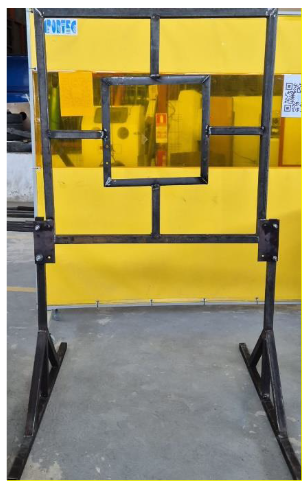
Figure 2.
Fabricated plate carrier.
Figure 2.
Fabricated plate carrier.
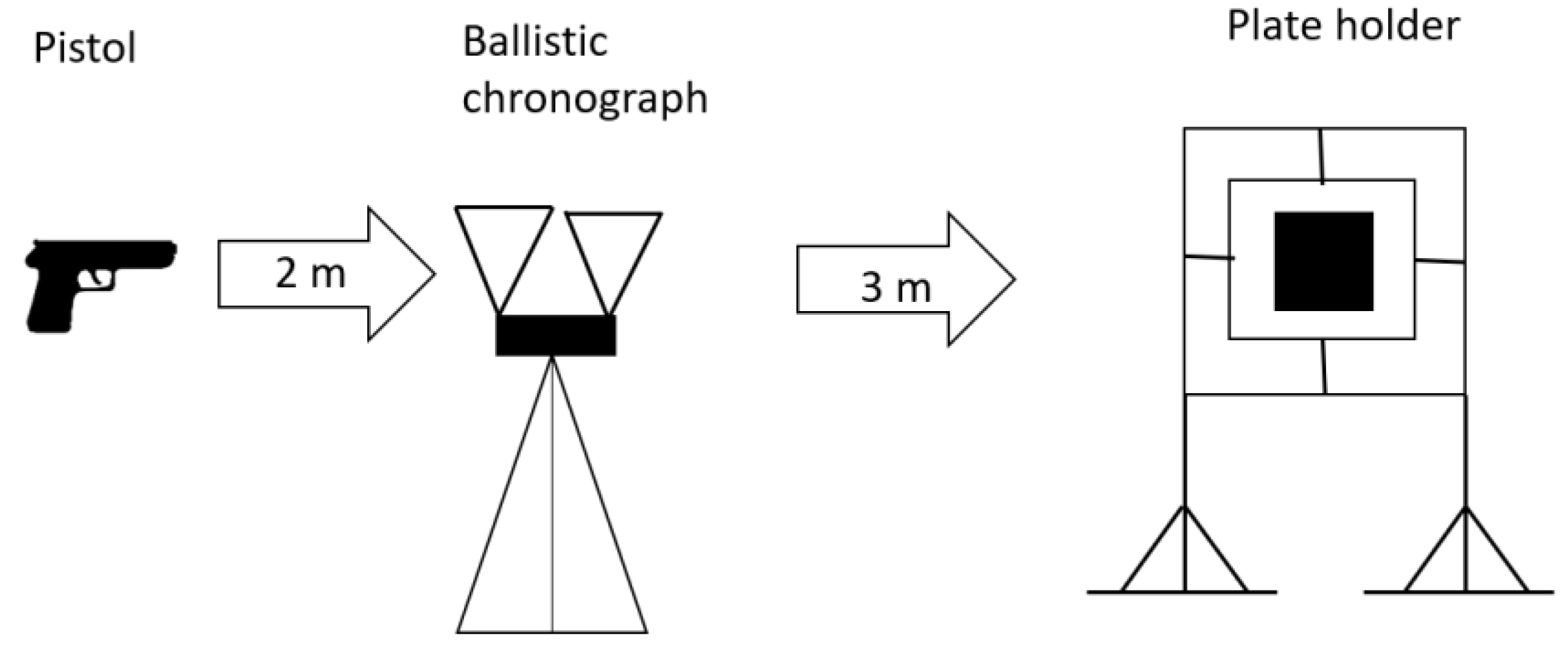
Figure 3.
Sketch of the ballistic test setup.
Figure 3.
Sketch of the ballistic test setup.
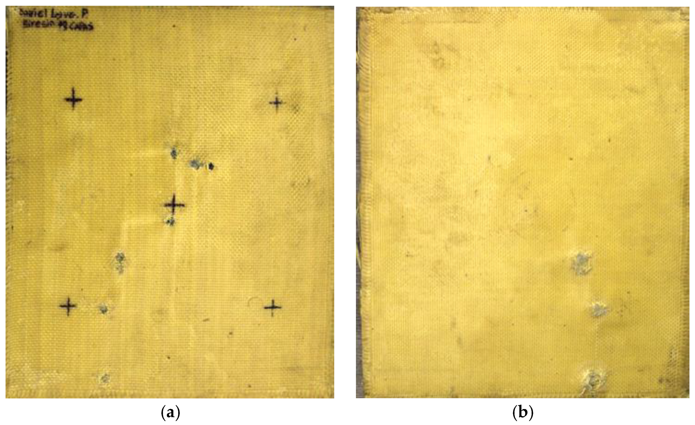
Figure 4.
(a) Ballistic impacts on Plate 1 front side. (b) Ballistic impacts on Plate 1 rear side.
Figure 4.
(a) Ballistic impacts on Plate 1 front side. (b) Ballistic impacts on Plate 1 rear side.
Figure 5.
(a) Ballistic impacts on
Plate 2 front side. (b) Ballistic impacts on Plate 2 rear side.
Figure 5.
(a) Ballistic impacts on
Plate 2 front side. (b) Ballistic impacts on Plate 2 rear side.
Figure 6.
(a) Ballistic impacts on Plate 3 front side. (b) Ballistic impacts on Plate 3 rear side.
Figure 6.
(a) Ballistic impacts on Plate 3 front side. (b) Ballistic impacts on Plate 3 rear side.
Figure 7.
(a) Ballistic impacts on Plate 4 front side. (b) Ballistic impacts on Plate 4 rear side.
Figure 7.
(a) Ballistic impacts on Plate 4 front side. (b) Ballistic impacts on Plate 4 rear side.
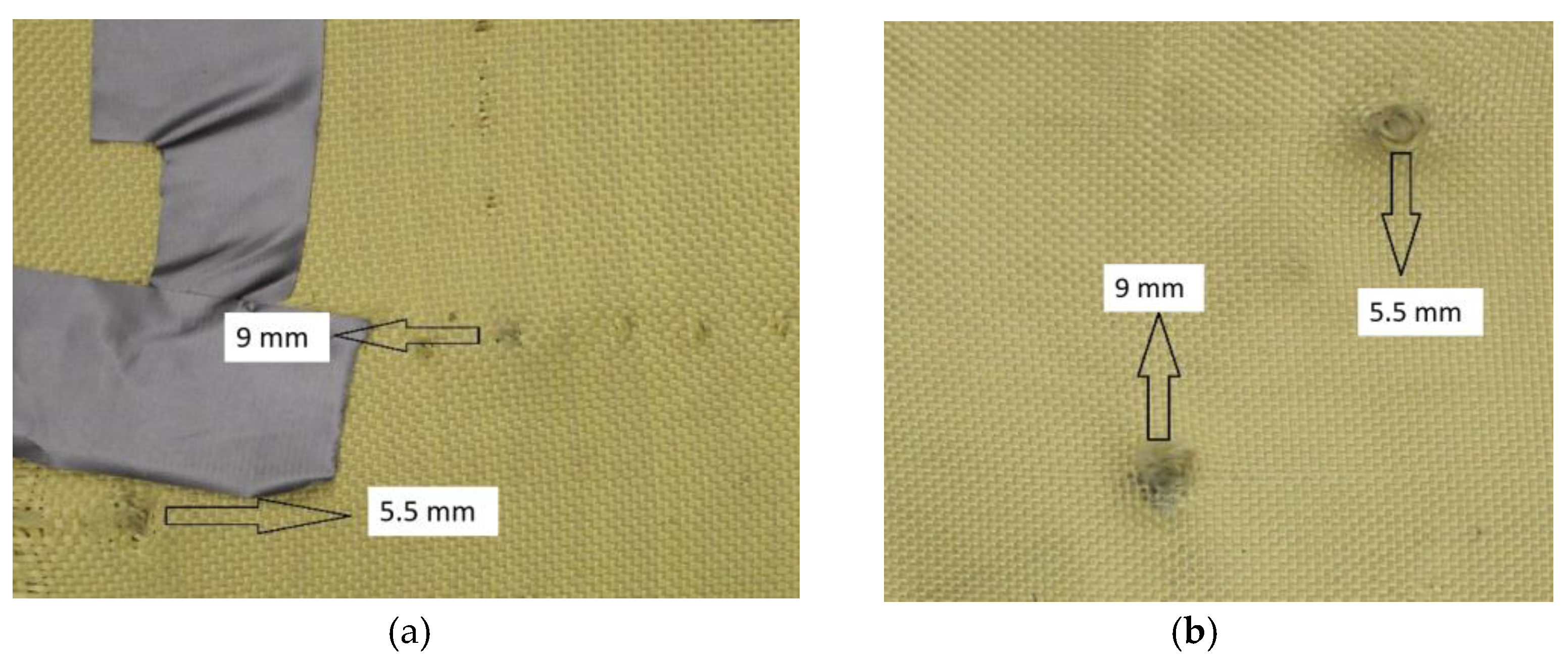
Figure 8.
(a) Impact of 9 mm on Plate 1. (b) 5.5 mm projectiles on Plate 1.
Figure 8.
(a) Impact of 9 mm on Plate 1. (b) 5.5 mm projectiles on Plate 1.
Figure 9.
Transition from 400 to 460 GSM grammage.
Figure 9.
Transition from 400 to 460 GSM grammage.
Figure 10.
(a) entry of the 9 mm projectile in layer 10 of Plate 1. (b) exit of the 9 mm projectile in layer 10 of Plate 1.
Figure 10.
(a) entry of the 9 mm projectile in layer 10 of Plate 1. (b) exit of the 9 mm projectile in layer 10 of Plate 1.
Figure 11.
(a) entry of the 9 mm projectile in layer 14 of Plate 1. (b) exit of the 9 mm projectile in layer 14 of Plate 1.
Figure 11.
(a) entry of the 9 mm projectile in layer 14 of Plate 1. (b) exit of the 9 mm projectile in layer 14 of Plate 1.
Figure 12.
(a) entry of the 9 mm projectile in layer 18 of Plate 1. (b) exit of the 9 mm projectile in layer 18 of Plate 1.
Figure 12.
(a) entry of the 9 mm projectile in layer 18 of Plate 1. (b) exit of the 9 mm projectile in layer 18 of Plate 1.
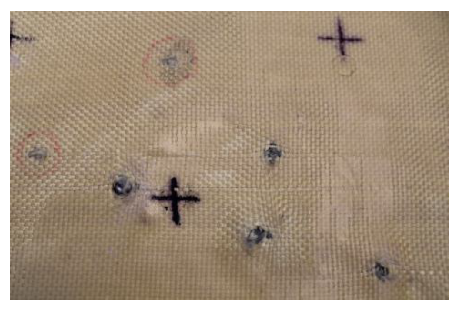
Figure 13.
Ballistic impacts on Plate 2.
Figure 13.
Ballistic impacts on Plate 2.
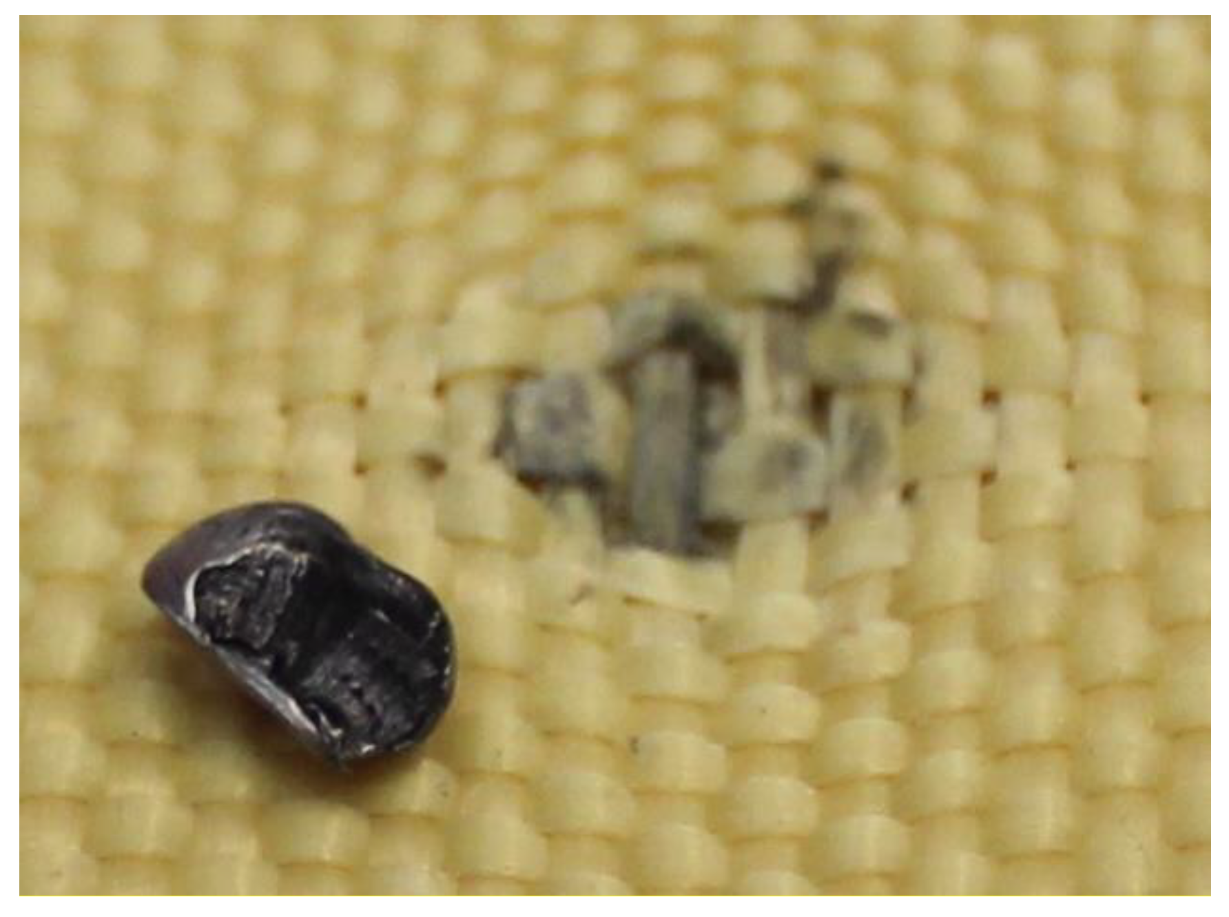
Figure 14.
(a) Projectile fragments in layer 2 on Plate 2. (b) Projectile fragments in layer 5 on Plate 2.
Figure 14.
(a) Projectile fragments in layer 2 on Plate 2. (b) Projectile fragments in layer 5 on Plate 2.
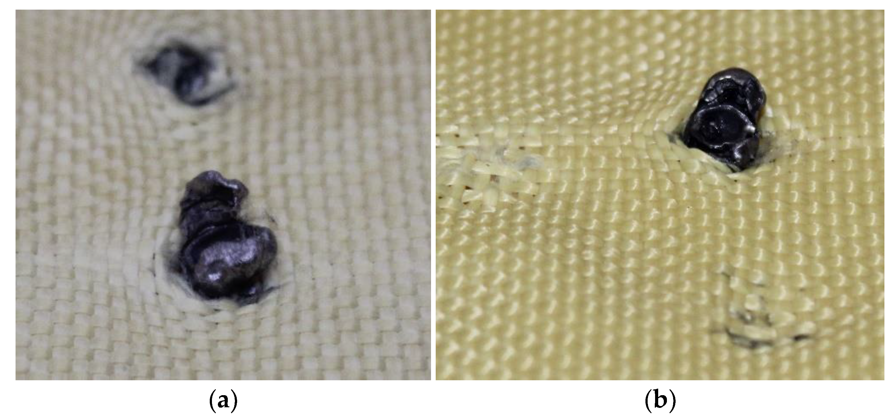
Figure 15.
(a) Projectile fragments in layer 2 on Plate 2. (b) Projectile fragments in layer 5 on Plate 2.
Figure 15.
(a) Projectile fragments in layer 2 on Plate 2. (b) Projectile fragments in layer 5 on Plate 2.
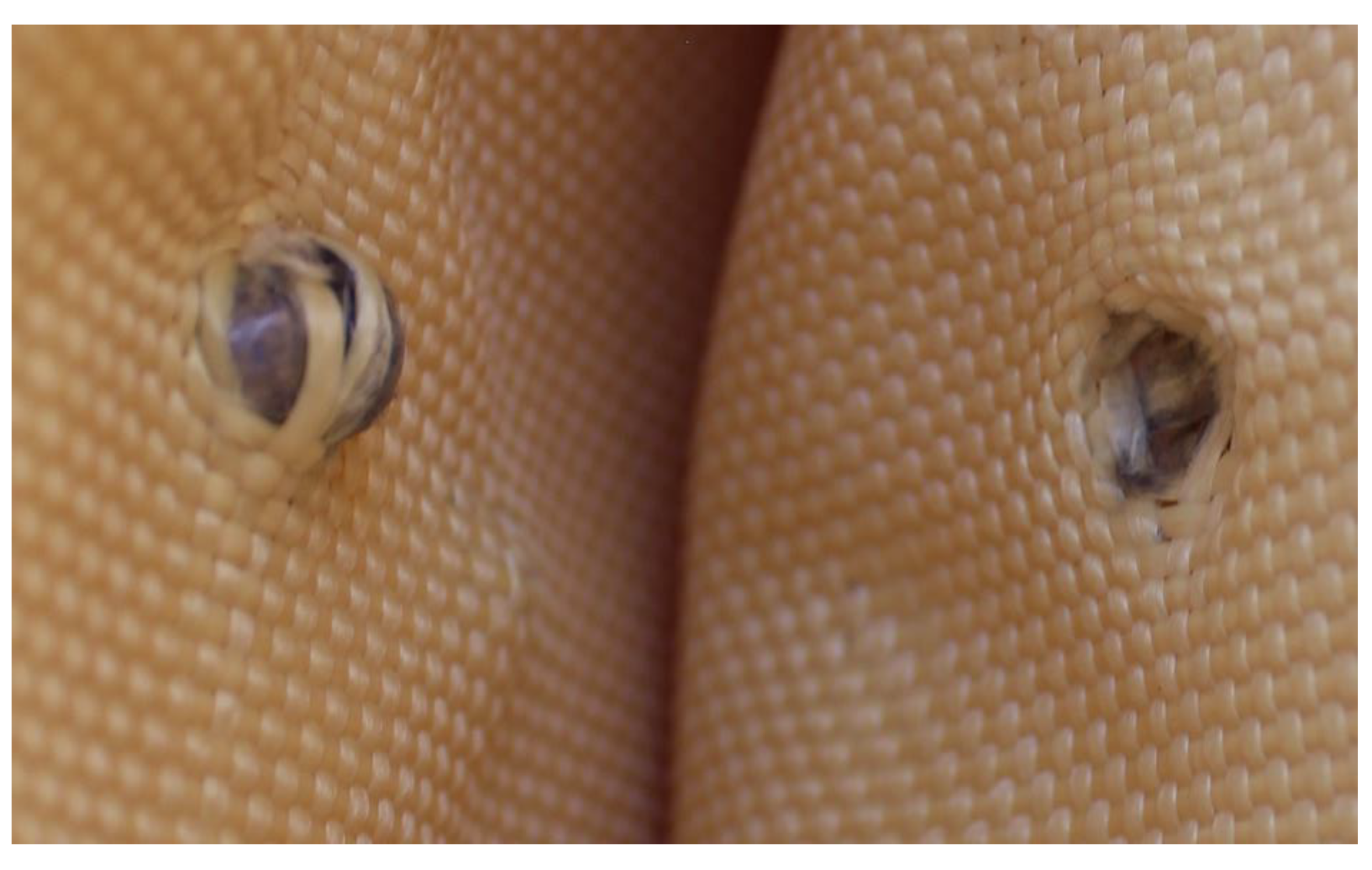
Figure 16.
(a) Projectile fragments in layer 5 on Plate 2. (b) Projectile fragments in layer 6 on Plate 2.
Figure 16.
(a) Projectile fragments in layer 5 on Plate 2. (b) Projectile fragments in layer 6 on Plate 2.
Figure 17.
Ballistic impacts on Plate 3.
Figure 17.
Ballistic impacts on Plate 3.
Figure 18.
(a) 9 mm projectile entry point and (b) 5.5 mm projectile entry point.
Figure 18.
(a) 9 mm projectile entry point and (b) 5.5 mm projectile entry point.
Figure 19.
(a) Projectile fragments in layer 2 on Plate 3. (b) Projectile fragments in layer 3 on Plate 3.
Figure 19.
(a) Projectile fragments in layer 2 on Plate 3. (b) Projectile fragments in layer 3 on Plate 3.
Figure 20.
Fragment of the 5.5 mm projectile in layer 5.
Figure 20.
Fragment of the 5.5 mm projectile in layer 5.
Figure 21.
Ballistic impacts on Plate 4.
Figure 21.
Ballistic impacts on Plate 4.
Figure 22.
(a) Projectile fragments in layer 4 on Plate 4. (b) Projectile fragments in layer 6 on Plate 4.
Figure 22.
(a) Projectile fragments in layer 4 on Plate 4. (b) Projectile fragments in layer 6 on Plate 4.
Figure 23.
Fragment of the 5.5 mm projectile in layer 6.
Figure 23.
Fragment of the 5.5 mm projectile in layer 6.
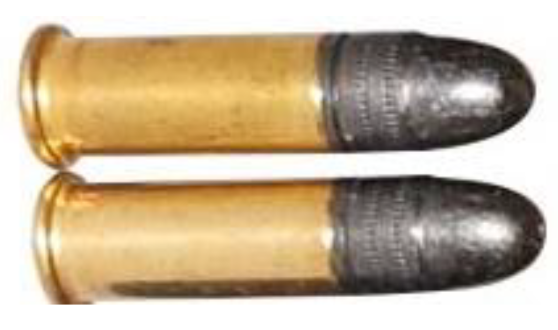
Figure 24.
.22 caliber bullets.
Figure 24.
.22 caliber bullets.
Figure 25.
.22 caliber bullets in Plate 2.
Figure 25.
.22 caliber bullets in Plate 2.
Figure 26.
.22 caliber bullets in Plate 3.
Figure 26.
.22 caliber bullets in Plate 3.
Figure 27.
.22 caliber bullets in Plate 4.
Figure 27.
.22 caliber bullets in Plate 4.
Table 1.
Properties of Kevlar.
Table 1.
Properties of Kevlar.
| Properties | Kevlar 29 |
|---|
| 1.44 |
| Young’s Modulus [GPa] | 83 |
| Tensile Strength [GPa] | 3.6 |
| Elongation at Break [%] | 4 |
Table 2.
Properties of Biresin Resin.
Table 2.
Properties of Biresin Resin.
| Properties | Biresin U1404 |
|---|
| 1.05 |
| Shore Hardness | A 40 |
| Tear Resistance [GPa] | 7 |
| Tensile Strength [GPa] | 3.0–4.0 |
| Elongation at Break [%] | 600 |
| Color | Reddish–Transparent |
Table 3.
Stacking Design.
Table 3.
Stacking Design.
| Plate | Total Number of Layers | Layer Distribution | Observations |
|---|
| Plate 1 | 18 | 3 layers of 400 GSM + 15 layers of 460 GSM | Reinforcement material only, without Biresin base matrix |
| Plate 2 | 18 | 3 layers of 400 GSM + 15 layers of 460 GSM | Includes Biresin base matrix |
| Plate 3 | 14 | 3 layers of 400 GSM + 11 layers of 460 GSM | Includes Biresin base matrix |
| Plate 4 | 10 | 3 layers of 400 GSM + 7 layers of 460 GSM | Includes Biresin base matrix |
Table 4.
Armor levels according to the NIJ 0108.01 standard.
Table 4.
Armor levels according to the NIJ 0108.01 standard.
| Armor Level | Ammunition Type | Nominal Mass | Caliber Length | Reference Velocity | Shots per Plate |
|---|
| I | 22 LRHV Lead | 2.6 g/40 gr | 15–16.5 cm | 320 ± 12 m/s | 5 |
| 38 Special RN Lead | 10.2 g/158 gr | 15–16.5 cm | 259 ± 15 m/s |
| IIA | 9 mm FMJ | 8.0 g/124 gr | 10–12 cm | 332 ± 12 m/s | 5 |
| 357 Mag JSP | 10.2 g/158 gr | 10–12 cm | 381 ± 15 m/s |
| II | 9 mm FMJ | 8.0 g/124 gr | 10–12 cm | 358 ± 12 m/s | 5 |
| 357 Mag JSP | 10.2 g/158 gr | 15–16.5 cm | 425 ± 15 m/s |
| IIIA | 9 mm FMJ | 8.0 g/124 gr | 24–26 cm | 426 ± 15 m/s | 5 |
| 44 Mag Lead SWC Gas Checked | 15.88 g/240 gr | 14–16 cm | 426 ± 15 m/s |
| III | 7.62 mm 308 | 9.7 g/150 gr | 56 cm | 838 ± 15 m/s | 5 |
| Winchester FMJ |
| IV | 30–06 AP | 10.8 g/166 gr | 56 cm | 868 ± 15 m/s | 5 |
Table 5.
Characteristics of the plates.
Table 5.
Characteristics of the plates.
| Characteristics of the Plates |
|---|
| Plate | Number of Layers | Composite Thickness [mm] | Surface Area [m2] | Weight [kg] | | Wm [gr] | Pm | Wj [gr] | Pj | Volume Fraction [%] |
|---|
| 1 | 18 | 8.1 | 0.075 | 0.583 | 7.77 | 0 | 0 | 48.5 | 1.44 | 100 |
| 2 | 18 | 11 | 0.075 | 0.824 | 10.99 | 240 | 1.051 | 583 | 1.44 | 63.94 |
| 3 | 14 | 8.8 | 0.075 | 0.627 | 8.36 | 179 | 1.051 | 449 | 1.44 | 64.67 |
| 4 | 10 | 5.7 | 0.075 | 0.4 | 5.33 | 90 | 1.051 | 310 | 1.44 | 71.54 |
Table 6.
Results for Plate 1.
Table 6.
Results for Plate 1.
| Plate 1 |
|---|
| N° | Caliber | Projectile Energy [gr] | Velocity [m/s] | Penetration | Energy [J] |
|---|
| 1 | Fiocchi 9 × 19 FMJ luger | 123 | 440 | yes | 772 |
| 2 | 5.5 | 38 | 330 | yes | 134 |
Table 7.
Results for Plate 2.
Table 7.
Results for Plate 2.
| Plate 2 |
|---|
| N° | Caliber | Projectile Energy [gr] | Velocity [m/s] | Penetration | Energy [J] |
|---|
| 1 | Fiocchi 9 × 19 FMJ luger | 123 | 440 | yes | 772 |
| 2 | Fiocchi 9 × 19 FMJ luger | 123 | 440 | yes | 772 |
| 3 | 5.5 | 38 | 330 | No | 134 |
| 4 | 5.5 | 38 | 330 | No | 134 |
Table 8.
Results for Plate 3.
Table 8.
Results for Plate 3.
| Plate 3 |
|---|
| N° | Caliber | Projectile Energy [gr] | Velocity [m/s] | Penetration | Energy [J] |
|---|
| 1 | Fiocchi 9 × 19 FMJ luger | 123 | 440 | yes | 772 |
| 2 | Fiocchi 9 × 19 FMJ luger | 123 | 440 | yes | 772 |
| 3 | 5.5 | 38 | 330 | No | 134 |
| 4 | 5.5 | 38 | 330 | No | 134 |
| 5 | 5.5 | 38 | 330 | No | 134 |
| 6 | 5.5 | 38 | 330 | No | 134 |
Table 9.
Results for Plate 4.
Table 9.
Results for Plate 4.
| Plate 4 |
|---|
| N° | Caliber | Projectile Energy [gr] | Velocity [m/s] | Penetration | Energy [J] |
|---|
| 1 | Fiocchi 9 × 19 FMJ luger | 123 | 440 | yes | 772 |
| 2 | Fiocchi 9 × 19 FMJ luger | 123 | 440 | yes | 772 |
| 3 | 5.5 | 38 | 330 | No | 134 |
| 4 | 5.5 | 38 | 330 | No | 134 |
| 5 | 5.5 | 38 | 330 | No | 134 |
| 6 | 5.5 | 38 | 330 | No | 134 |


 ,
, 


