
Interfacial Interlocking of Carbon Fiber-Reinforced Polymer Composites: A Short Review

Abstract
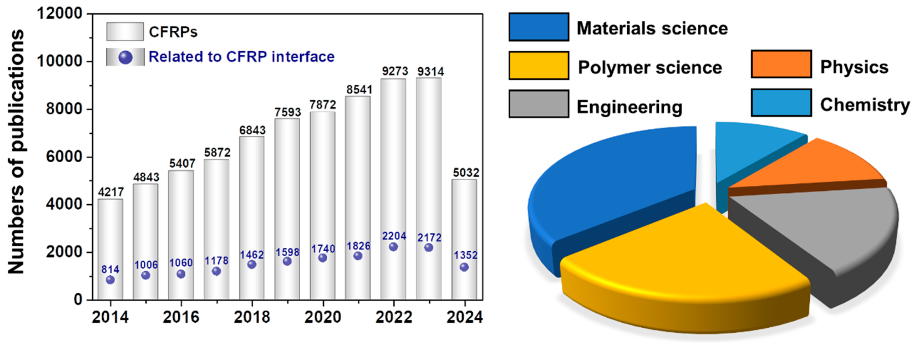
1. Introduction
2. Surface Modifications
2.1. Wet Treatments
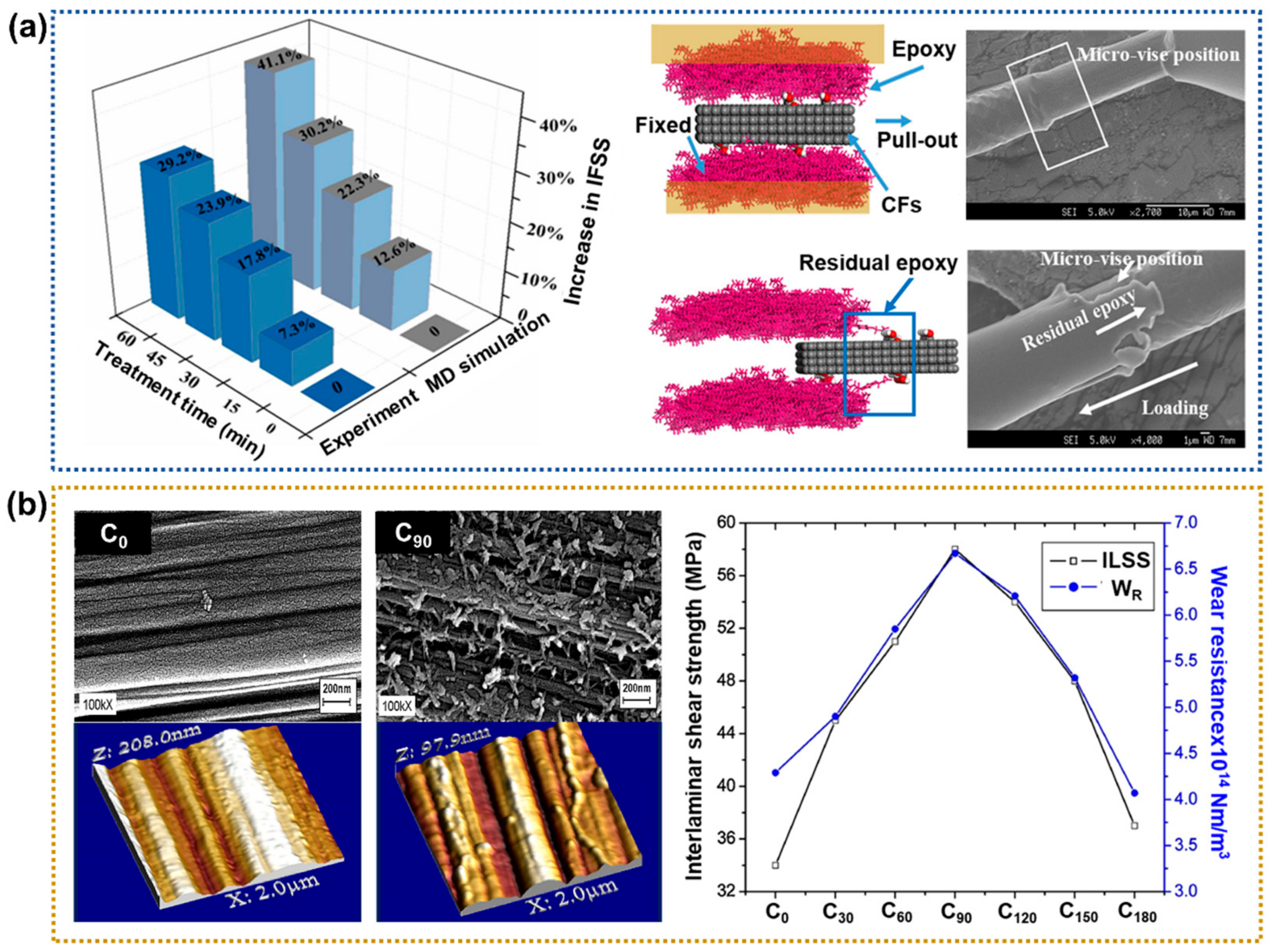
2.1.1. Acid Treatment
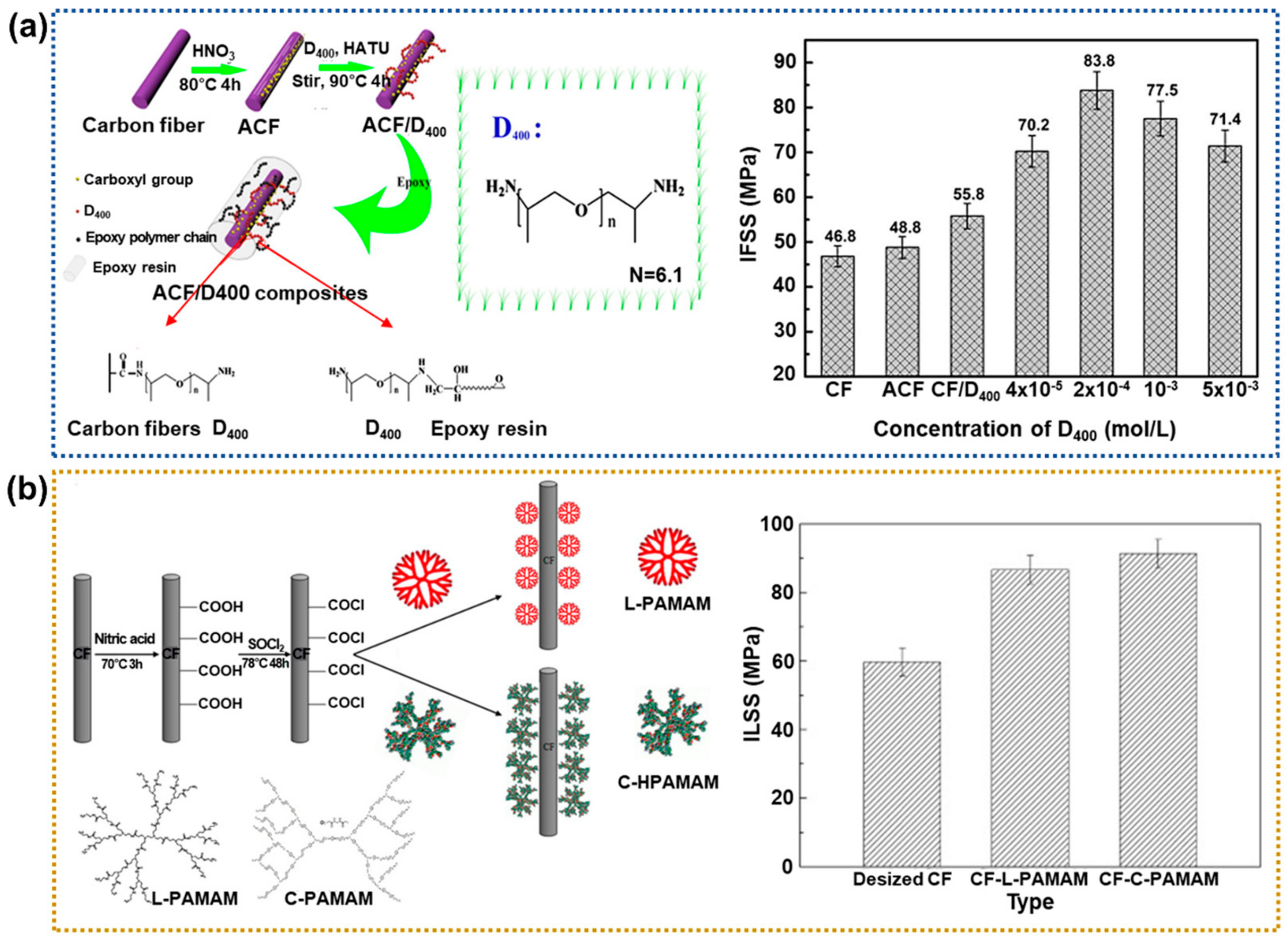
2.1.2. Amine Treatment
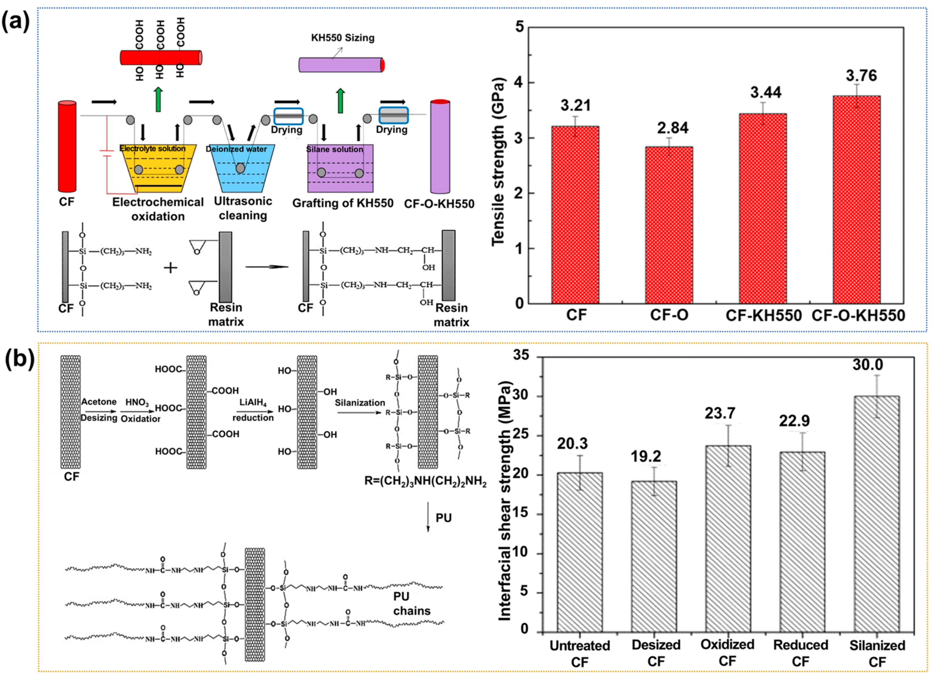
2.1.3. Silane Coupling Treatment
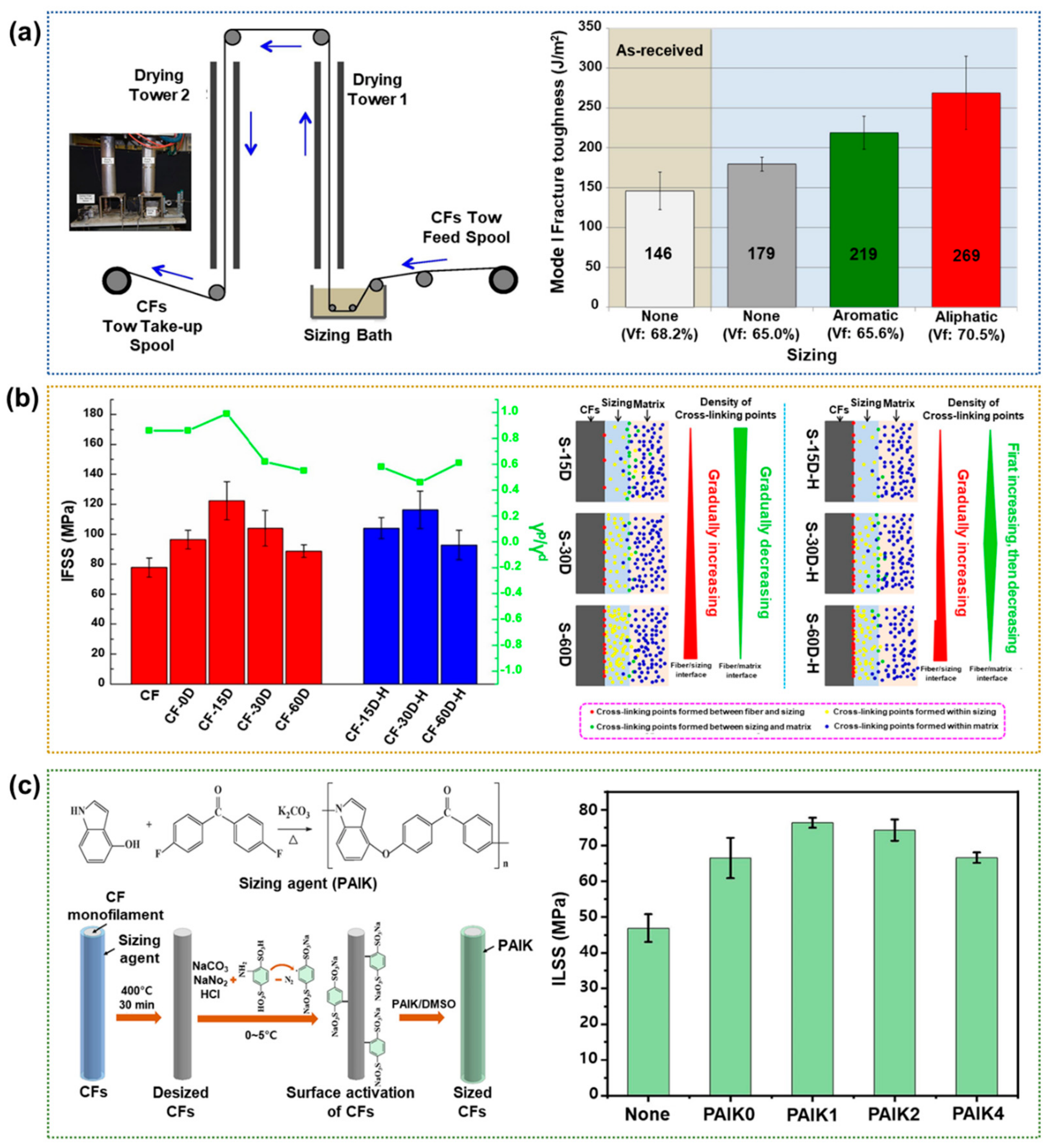
2.1.4. Sizing Treatment
2.1.5. Coating
2.2. Electrochemical Treatments
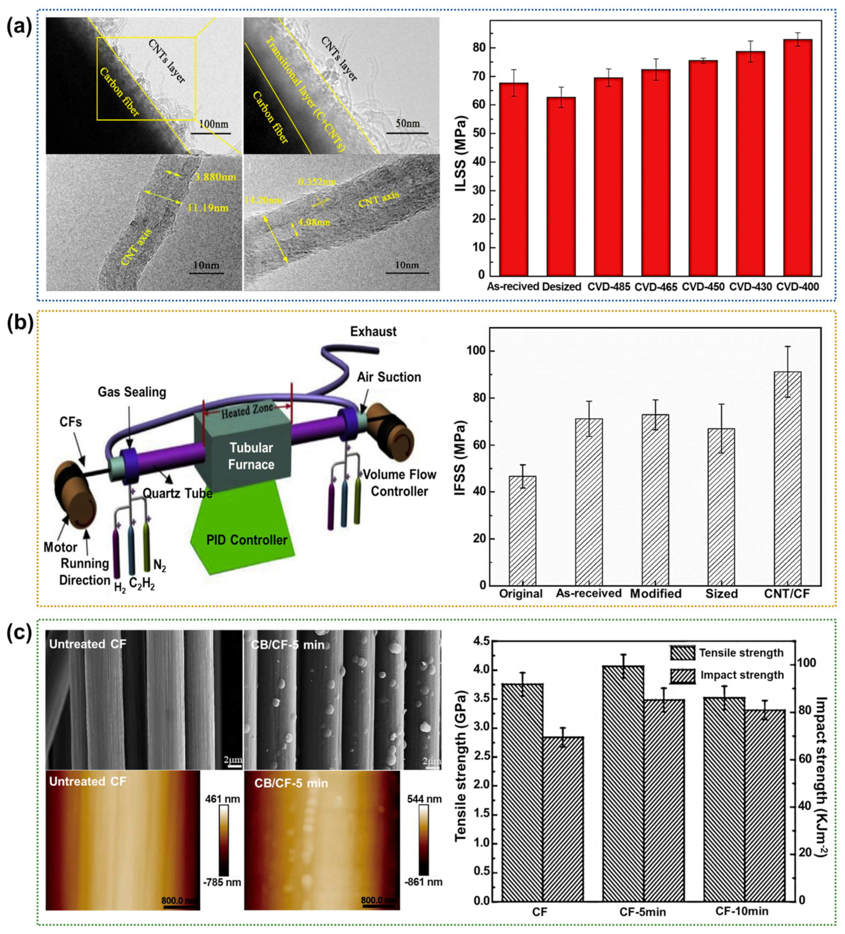
2.2.1. Chemical Vapor Deposition (CVD)
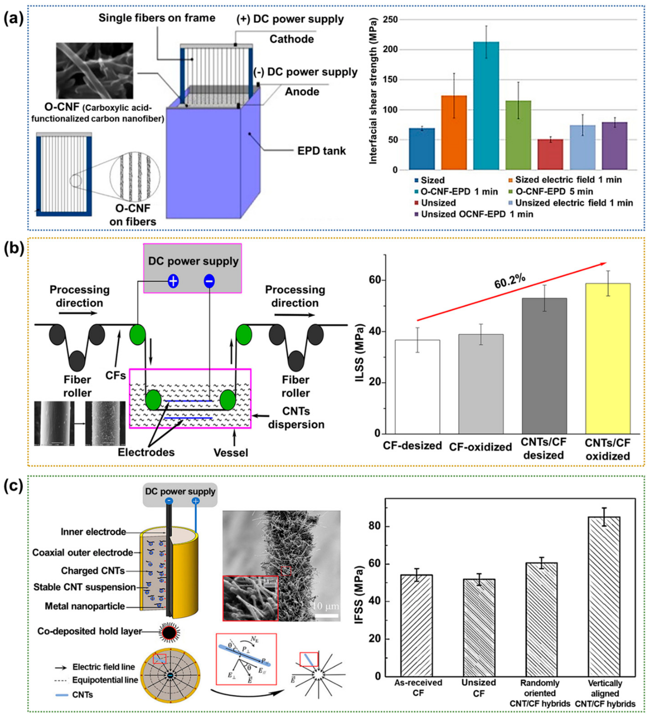
2.2.2. Electrophoretic Deposition (EPD)
2.3. Dry Treatments
2.3.1. Plasma Treatment
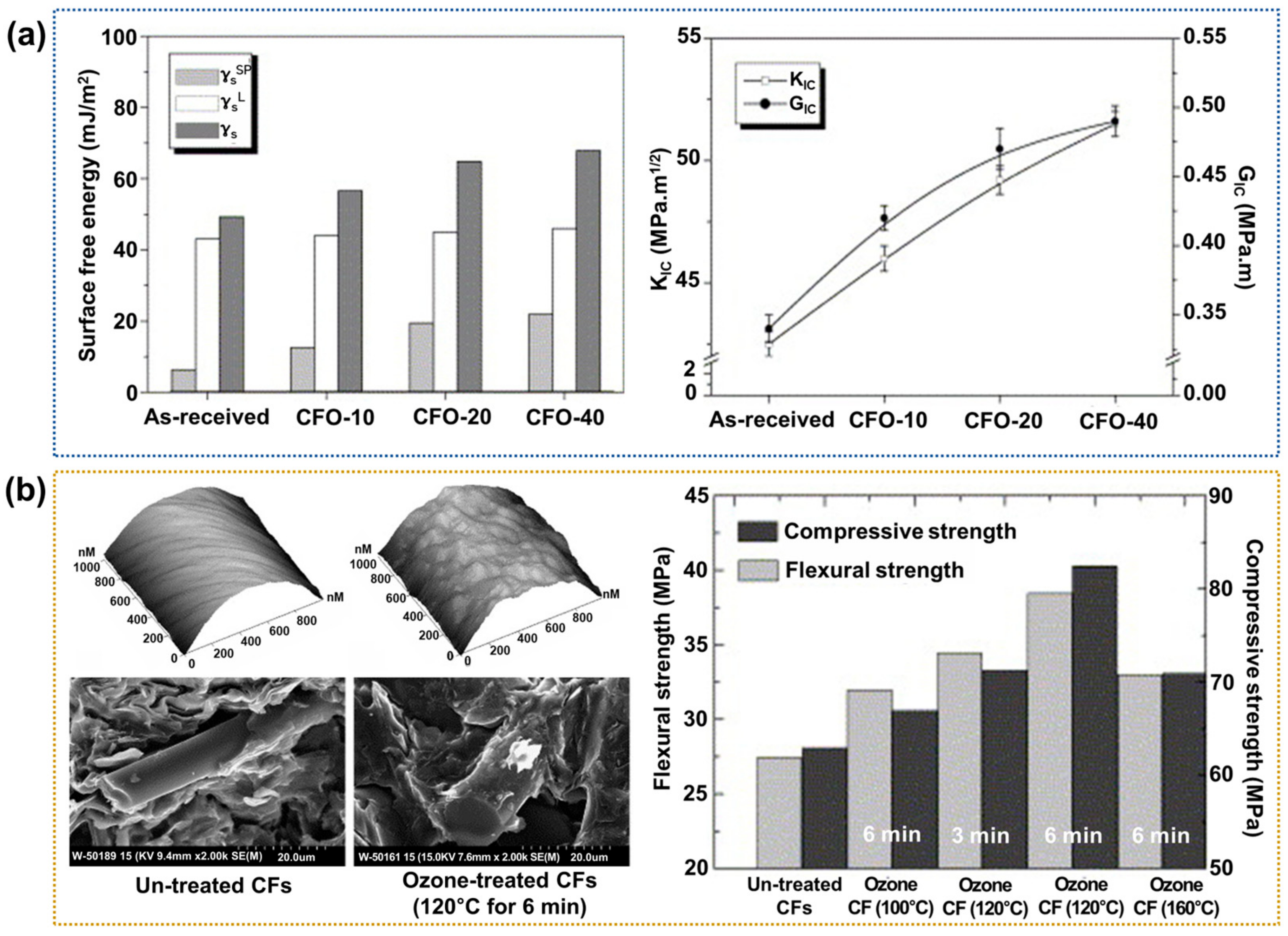
2.3.2. Ozone Treatment
2.4. Polymer Matrix Modifications
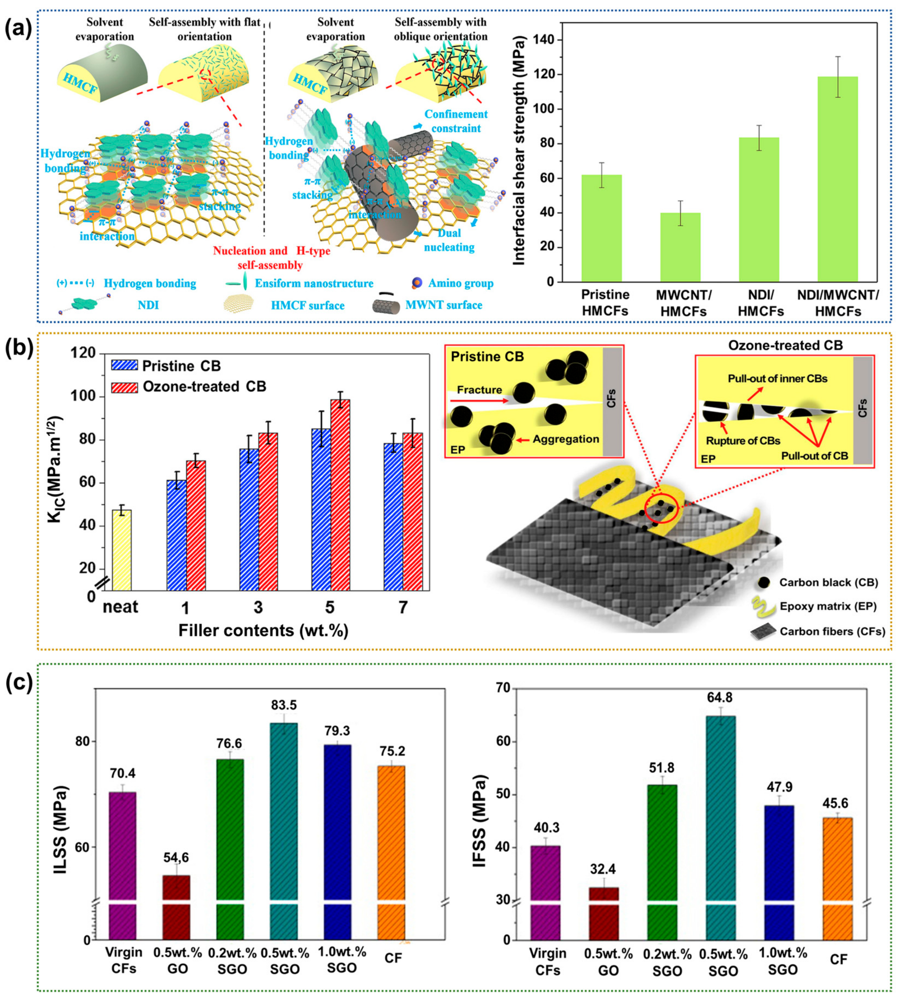
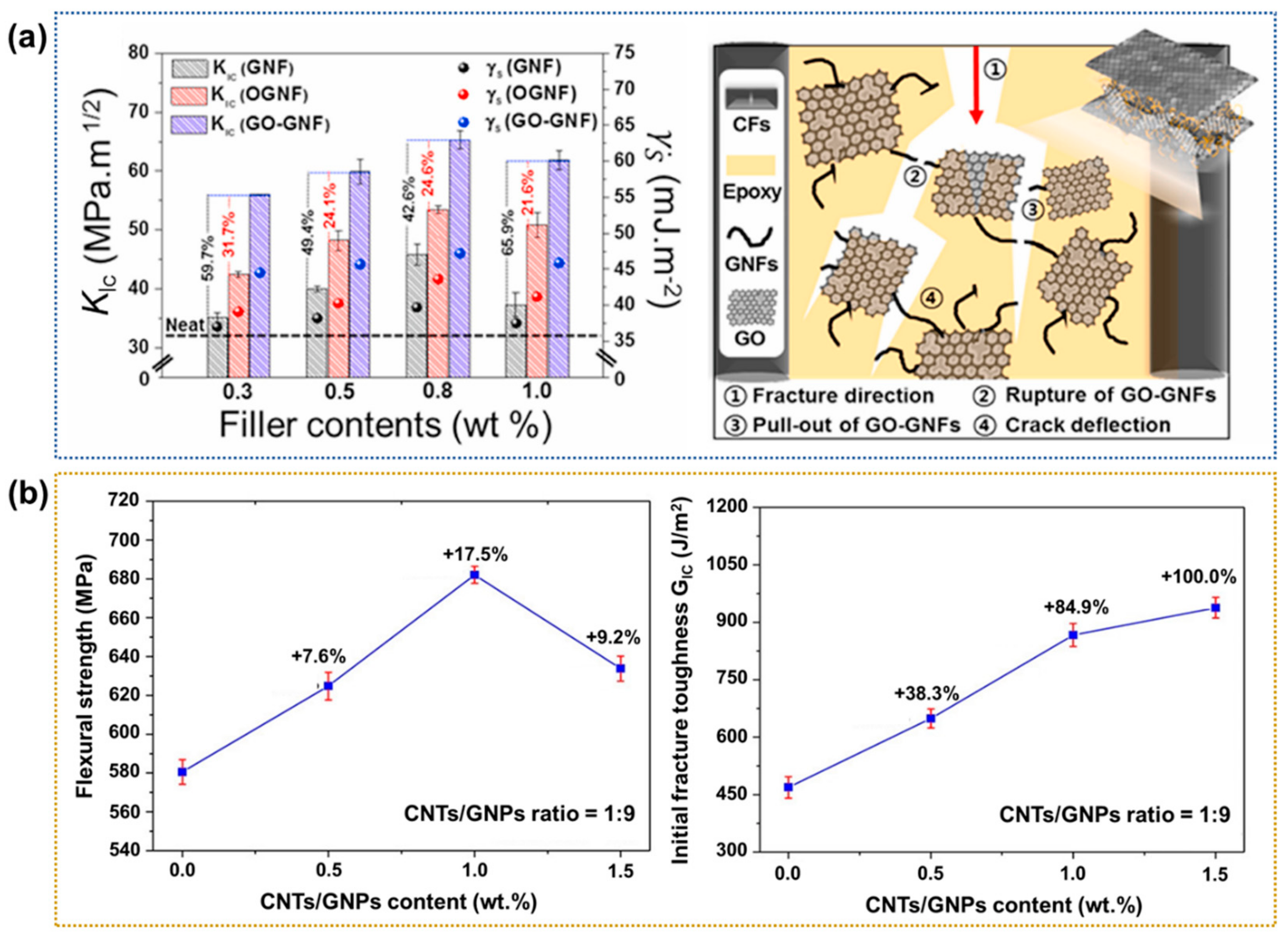
Addition of Nanofillers to the Polymer Matrices
3. Perspectives and Conclusions
Author Contributions
Funding
Data Availability Statement
Conflicts of Interest
References
- Yu, K.; Shi, Q.; Dunn, M.L.; Wang, T.; Qi, H.J. Carbon fiber reinforced thermoset composite with near 100% recyclability. Adv. Funct. Mater. 2016, 26, 6098–6106. [Google Scholar] [CrossRef]
- Xu, Z.; Gao, C. Graphene fiber: A new trend in carbon fibers. Mater. Today 2015, 18, 480–492. [Google Scholar] [CrossRef]
- Dresselhaus, M.S.; Dresselhaus, G.; Saito, R. Carbon fibers based on C60 and their symmetry. Phys. Rev. B 1992, 45, 6234. [Google Scholar] [CrossRef]
- Das, T.K.; Ghosh, P.; Das, N.C. Preparation, development, outcomes, and application versatility of carbon fiber-based polymer composites: A review. Adv. Compos. Hybrid Mater. 2019, 2, 214–233. [Google Scholar] [CrossRef]
- Jin, F.L.; Park, S.J. Preparation and characterization of carbon fiber-reinforced thermosetting composites: A review. Carbon Lett. 2015, 16, 67–77. [Google Scholar] [CrossRef]
- Yang, K.; Guan, J.; Numata, K.; Wu, C.; Wu, S.; Shao, Z.; Ritchie, R.O. Integrating tough Antheraea pernyi silk and strong carbon fibres for impact-critical structural composites. Nat. Commun. 2019, 10, 3786. [Google Scholar] [CrossRef]
- Godara, A.; Mezzo, L.; Luizi, F.; Warrier, A.; Lomov, S.V.; van Vuure, A.W.; Gorbatikh, L.; Moldenaers, P.; Verpoest, I. Influence of carbon nanotube reinforcement on the processing and the mechanical behaviour of carbon fiber/epoxy composites. Carbon 2009, 47, 2914–2923. [Google Scholar] [CrossRef]
- Yadav, R.; Zabihi, O.; Fakhrhoseini, S.; Nazarloo, H.A.; Kiziltas, A.; Blanchard, P.; Naebe, M. Lignin derived carbon fiber and nanofiber: Manufacturing and applications. Compos. B-Eng. 2023, 255, 110613. [Google Scholar] [CrossRef]
- Afroze, J.D.; Tong, L.; Abden, M.J.; Chen, Y. Multifunctional hierarchical graphene-carbon fiber hybrid aerogels for strain sensing and energy storage. Adv. Compos. Hybrid Mater. 2023, 6, 18. [Google Scholar] [CrossRef]
- Wang, S.; Chen, S.; Sun, J.; Liu, Z.; He, D.; Xu, S. Effects of Rare Earth Oxides on the Mechanical and Tribological Properties of Phenolic-Based Hybrid Nanocomposites. Polymers 2023, 16, 131. [Google Scholar] [CrossRef]
- Burgos Pintos, P.; Moreno Sánchez, D.; Delgado, F.J.; Sanz de León, A.; Molina, S.I. Influence of the Carbon Fiber Length Distribution in Polymer Matrix Composites for Large Format Additive Manufacturing via Fused Granular Fabrication. Polymers 2023, 16, 60. [Google Scholar] [CrossRef] [PubMed]
- Lee, H.; Ohsawa, I.; Takahashi, J. Effect of plasma surface treatment of recycled carbon fiber on carbon fiber-reinforced plastics (CFRP) interfacial properties. Appl. Surf. Sci. 2015, 328, 241–246. [Google Scholar] [CrossRef]
- Liu, L.; Jia, C.; He, J.; Zhao, F.; Fan, D.; Xing, L.; Wang, M.; Wang, F.; Jiang, Z.; Huang, Y. Interfacial characterization, control and modification of carbon fiber reinforced polymer composites. Compos. Sci. Technol. 2015, 121, 56–72. [Google Scholar] [CrossRef]
- Wu, D.; Yao, Z.; Sun, X.; Liu, X.; Liu, L.; Zhang, R.; Wang, C. Mussel-tailored carbon fiber/carbon nanotubes interface for elevated interfacial properties of carbon fiber/epoxy composites. Chem. Eng. J. 2022, 429, 132449. [Google Scholar] [CrossRef]
- Yan, H.; Hu, D.; Dai, Y.; Zhang, X.; Yuan, H.; Li, W.; Huang, X.; Tan, Y. Self-assembly of carbon nanomaterials onto carbon fiber to improve the interfacial properties of epoxy composites. J. Mater. Sci. Technol. 2023, 161, 44–49. [Google Scholar] [CrossRef]
- Yan, C.; Zhu, Y.; Liu, D.; Xu, H.; Chen, G.; Chen, M.; Cai, G. Improving interfacial adhesion and mechanical properties of carbon fiber reinforced polyamide 6 composites with environment-friendly water-based sizing agent. Compos. Part B-Eng. 2023, 258, 110675. [Google Scholar] [CrossRef]
- Li, N.; Cheng, S.; Wang, B.; Zong, L.; Bao, Q.; Wu, G.; Hu, F.; Wang, J.; Liu, C.; Jian, X. Chemical grafting of graphene onto carbon fiber to produce composites with improved interfacial properties via sizing process: A step closer to industrial production. Compos. Sci. Technol. 2023, 231, 109822. [Google Scholar] [CrossRef]
- Drzal, L.T.; Rich, M.J.; Lloyd, P.F. Adhesion of graphite fibers to epoxy matrices: I. The role of fiber surface treatment. J. Adhes. 1983, 16, 1–30. [Google Scholar] [CrossRef]
- Khandelwal, S.; Rhee, K.Y. Recent advances in basalt-fiber-reinforced composites: Tailoring the fiber-matrix interface. Compos. Part B-Eng. 2020, 192, 108011. [Google Scholar] [CrossRef]
- Zhandarov, S.; Mäder, E. Characterization of fiber/matrix interface strength: Applicability of different tests, approaches and parameters. Compos. Sci. Technol. 2005, 65, 149–160. [Google Scholar] [CrossRef]
- Huo, Y.; Lu, D.; Wang, Z.; Liu, Y.; Chen, Z.; Yang, Y. Bending behavior of strain hardening cementitious composites based on the combined fiber-interface constitutive model. Comput. Struct. 2023, 281, 107017. [Google Scholar] [CrossRef]
- Zhang, K.; Yuan, Q.; Huang, T.; Zuo, S.; Yao, H. Utilization of novel stranded steel fiber to enhance fiber–matrix interface of cementitious composites. Constr. Build. Mater. 2023, 369, 130525. [Google Scholar] [CrossRef]
- Tang, H.; Sun, J.; He, J.; Wu, P. Research progress of interface conditions and tribological reactions: A review. J. Ind. Eng. Chem. 2021, 94, 105–121. [Google Scholar] [CrossRef]
- Georgakopoulos-Soares, I.; Papazoglou, E.L.; Karmiris-Obratański, P.; Karkalos, N.E.; Markopoulos, A.P. Surface antibacterial properties enhanced through engineered textures and surface roughness: A review. Colloid. Surf. B 2023, 231, 113584. [Google Scholar] [CrossRef] [PubMed]
- Chhetri, S.; Bougherara, H. A comprehensive review on surface modification of UHMWPE fiber and interfacial properties. Compos. Part A Appl. Sci. Manuf. 2021, 140, 106146. [Google Scholar] [CrossRef]
- Shelly, D.; Lee, S.Y.; Park, S.J. Compatibilization of ultra-high molecular weight polyethylene (UHMWPE) fibers and their composites for superior mechanical performance: A concise review. Compos. Part B-Eng. 2024, 275, 111294. [Google Scholar] [CrossRef]
- Tiwari, S.; Bijwe, J.J.P.T. Surface treatment of carbon fibers-a review. Procedia Technol. 2014, 14, 505–512. [Google Scholar] [CrossRef]
- Li, H.; Liebscher, M.; Zhao, D.; Yin, B.; Du, Y.; Yang, J.; Kaliske, M.; Mechtcherine, V. A review of carbon fiber surface modification methods for tailor-made bond behavior with cementitious matrices. Prog. Mater. Sci. 2023, 132, 101040. [Google Scholar] [CrossRef]
- Qiu, C.; Jiang, L.; Gao, Y.; Sheng, L. Effects of oxygen-containing functional groups on carbon materials in supercapacitors: A review. Mater. Des. 2023, 230, 111952. [Google Scholar] [CrossRef]
- Shi, L.; Song, G.; Li, P.; Li, X.; Pan, D.; Huang, Y.; Ma, L.; Guo, Z. Enhancing interfacial performance of epoxy resin composites via in-situ nucleophilic addition polymerization modification of carbon fibers with hyperbranched polyimidazole. Compos. Sci. Technol. 2021, 201, 108522. [Google Scholar] [CrossRef]
- Huan, X.; Shi, K.; Yan, J.; Lin, S.; Li, Y.; Jia, X.; Yang, X. High performance epoxy composites prepared using recycled short carbon fiber with enhanced dispersibility and interfacial bonding through polydopamine surface-modification. Compos. Part B-Eng. 2020, 193, 107987. [Google Scholar] [CrossRef]
- Zeng, J.J.; Hao, Z.H.; Liang, Q.J.; Zhuge, Y.; Liu, Y. Durability assessment of GFRP bars exposed to combined accelerated aging in alkaline solution and a constant load. Eng. Struct. 2023, 297, 116990. [Google Scholar] [CrossRef]
- Weinstein, R.D.; Ferens, A.R.; Orange, R.J.; Lemaire, P. Oxidative dehydrogenation of ethanol to acetaldehyde and ethyl acetate by graphite nanofibers. Carbon 2011, 49, 701–707. [Google Scholar] [CrossRef]
- Olivier, J.P.; Winter, M. Determination of the absolute and relative extents of basal plane surface area and “non-basal plane surface” area of graphites and their impact on anode performance in lithium ion batteries. J. Power Sources 2001, 97, 151–155. [Google Scholar] [CrossRef]
- McHugh, J.G.; Mouratidis, P.; Impellizzeri, A.; Jolley, K.; Erbahar, D.; Ewels, C.P. Prismatic edge dislocations in graphite. Carbon 2022, 188, 401–419. [Google Scholar] [CrossRef]
- Qing, J.; Richards, V.L.; Van Aken, D.C. Growth stages and hexagonal-rhombohedral structural arrangements in spheroidal graphite observed in ductile iron. Carbon 2017, 116, 456–469. [Google Scholar] [CrossRef]
- Fukunaga, A.; Ueda, S. Anodic surface oxidation for pitch-based carbon fibers and the interfacial bond strengths in epoxy matrices. Compos. Sci. Technol. 2000, 60, 249–254. [Google Scholar] [CrossRef]
- Zhou, W.; Bang, S.; Kurita, H.; Miyazaki, T.; Fan, Y.; Kawasaki, A. Interface and interfacial reactions in multi-walled carbon nanotube-reinforced aluminum matrix composites. Carbon 2016, 96, 919–928. [Google Scholar] [CrossRef]
- Donnet, J.B.; Brendle, M.; Dhami, T.L.; Bahl, O.P. Plasma treatment effect on the surface energy of carbon and carbon fibers. Carbon 1986, 24, 757–770. [Google Scholar] [CrossRef]
- Karger-Kocsis, J.; Mahmood, H.; Pegoretti, A. All-carbon multi-scale and hierarchical fibers and related structural composites: A review. Compos. Sci. Technol. 2020, 186, 107932. [Google Scholar] [CrossRef]
- Chen, X.; Xu, H.; Liu, D.; Yan, C.; Zhu, Y. A novel and facile fabrication of polyphosphazene nanotube/carbon fiber multi-scale hybrid reinforcement and its enhancing effect on the interfacial properties of epoxy composites. Compos. Sci. Technol. 2019, 169, 34–44. [Google Scholar] [CrossRef]
- Kim, J.W.; Gardner, J.M.; Sauti, G.; Wincheski, R.A.; Jensen, B.D.; Wise, K.E.; Siochi, E.J. Multi-scale hierarchical carbon nanotube fiber reinforced composites towards enhancement of axial/transverse strength and fracture toughness. Compos. Part A Appl. Sci. Manuf. 2023, 167, 107449. [Google Scholar] [CrossRef]
- Zhou, M.; Tan, S.; Wang, J.; Wu, Y.; Liang, L.; Ji, G. “Three-in-One” multi-scale structural design of carbon fiber-based composites for personal electromagnetic protection and thermal management. Nano-Micro Lett. 2023, 15, 176. [Google Scholar] [CrossRef]
- Narkis, M.; Chen, E.J.H.; Pipes, R.B. Review of methods for characterization of interfacial fiber-matrix interactions. Polym. Compos. 1988, 9, 245–251. [Google Scholar] [CrossRef]
- Dai, Z.; Shi, F.; Zhang, B.; Li, M.; Zhang, Z. Effect of sizing on carbon fiber surface properties and fibers/epoxy interfacial adhesion. Appl. Surf. Sci. 2011, 257, 6980–6985. [Google Scholar] [CrossRef]
- Valadez-Gonzalez, A.; Cervantes-Uc, J.M.; Olayo, R.J.I.P.; Herrera-Franco, P.J. Effect of fiber surface treatment on the fiber–matrix bond strength of natural fiber reinforced composites. Compos. Part B-Eng. 1999, 30, 309–320. [Google Scholar] [CrossRef]
- Zhang, G.; Sun, S.; Yang, D.; Dodelet, J.P.; Sacher, E. The surface analytical characterization of carbon fibers functionalized by H2SO4/HNO3 treatment. Carbon 2008, 46, 196–205. [Google Scholar] [CrossRef]
- Langston, T.A.; Granata, R.D. Influence of nitric acid treatment time on the mechanical and surface properties of high-strength carbon fibers. J. Compos. Mater. 2014, 48, 259–276. [Google Scholar] [CrossRef]
- Pittman Jr, C.U.; He, G.R.; Wu, B.; Gardner, S.D. Chemical modification of carbon fiber surfaces by nitric acid oxidation followed by reaction with tetraethylenepentamine. Carbon 1997, 35, 317–331. [Google Scholar] [CrossRef]
- Cuiqin, F.; Jinxian, W.; Julin, W.; Tao, Z. Modification of carbon fiber surfaces via grafting with Meldrum’s acid. Appl. Surf. Sci. 2015, 356, 9–17. [Google Scholar] [CrossRef]
- Wang, H.; Jin, K.; Wang, C.; Guo, X.; Chen, Z.; Tao, J. Effect of fiber surface functionalization on shear behavior at carbon fiber/epoxy interface through molecular dynamics analysis. Compos. Part A Appl. Sci. Manuf. 2019, 126, 105611. [Google Scholar] [CrossRef]
- Tiwari, S.; Bijwe, J.; Panier, S. Optimization of surface treatment to enhance fiber–matrix interface and performance of composites. Wear 2012, 274, 326–334. [Google Scholar] [CrossRef]
- Peng, Q.; Li, Y.; He, X.; Lv, H.; Hu, P.; Shang, Y.; Wang, C.; Wang, R.; Sritharan, T.; Du, S. Interfacial enhancement of carbon fiber composites by poly (amido amine) functionalization. Compos. Sci. Technol. 2013, 74, 37–42. [Google Scholar] [CrossRef]
- Gao, B.; Zhang, R.; He, M.; Wang, C.; Liu, L.; Zhao, L.; Wen, Z.; Ding, Z. Interfacial microstructure and mechanical properties of carbon fiber composites by fiber surface modification with poly (amidoamine)/polyhedral oligomeric silsesquioxane. Compos. Part A Appl. Sci. Manuf. 2016, 90, 653–661. [Google Scholar] [CrossRef]
- Andideh, M.; Esfandeh, M. Effect of surface modification of electrochemically oxidized carbon fibers by grafting hydroxyl and amine functionalized hyperbranched polyurethanes on interlaminar shear strength of epoxy composites. Carbon 2017, 123, 233–242. [Google Scholar] [CrossRef]
- Xu, H.; Zhang, X.; Liu, D.; Chun, Y.; Fan, X. A high efficient method for introducing reactive amines onto carbon fiber surfaces using hexachlorocyclophosphazene as a new coupling agent. Appl. Surf. Sci. 2014, 320, 43–51. [Google Scholar] [CrossRef]
- Wang, C.; Chen, L.; Li, J.; Sun, S.; Ma, L.; Wu, G.; Zhao, F.; Jiang, B.; Huang, Y. Enhancing the interfacial strength of carbon fiber reinforced epoxy composites by green grafting of poly (oxypropylene) diamines. Compos. Part A Appl. Sci. Manuf. 2017, 99, 58–64. [Google Scholar] [CrossRef]
- Gao, B.; Zhang, R.; Wang, C. Enhanced mechanical properties of carbon fiber composites by grafting different structural poly (amido amine) onto fiber surface. Polym. Test. 2016, 56, 192–199. [Google Scholar] [CrossRef]
- He, J.M.; Huang, Y.D. Effect of silane-coupling agents on interfacial properties of CF/PI composites. J. Appl. Polym. Sci. 2007, 106, 2231–2237. [Google Scholar] [CrossRef]
- Taieh, N.K.; Khudhur, S.K.; Fahad, E.A.A.; Zhou, Z.; Hui, D. High mechanical performance of 3-aminopropyl triethoxy silane/epoxy cured in a sandwich construction of 3D carbon felts foam and woven basalt fibers. Nanotechnol. Rev. 2023, 12, 20220519. [Google Scholar] [CrossRef]
- Song, W.; Gu, A.; Liang, G.; Yuan, L. Effect of the surface roughness on interfacial properties of carbon fibers reinforced epoxy resin composites. Appl. Surf. Sci. 2011, 257, 4069–4074. [Google Scholar] [CrossRef]
- Wen, Z.; Xu, C.; Qian, X.; Zhang, Y.; Wang, X.; Song, S.; Dai, M.; Zhang, C. A two-step carbon fiber surface treatment and its effect on the interfacial properties of CF/EP composites: The electrochemical oxidation followed by grafting of silane coupling agent. Appl. Surf. Sci. 2019, 486, 546–554. [Google Scholar] [CrossRef]
- Jiang, S.; Li, Q.; Zhao, Y.; Wang, J.; Kang, M. Effect of surface silanization of carbon fiber on mechanical properties of carbon fiber reinforced polyurethane composites. Compos. Sci. Technol. 2015, 110, 87–94. [Google Scholar] [CrossRef]
- Yao, L.; Li, M.; Wu, Q.; Dai, Z.; Gu, Y.; Li, Y.; Zhang, Z. Comparison of sizing effect of T700 grade carbon fiber on interfacial properties of fiber/BMI and fiber/epoxy. Appl. Surf. Sci. 2012, 263, 326–333. [Google Scholar] [CrossRef]
- Liu, H.; Zhao, Y.; Li, N.; Li, S.; Li, X.; Liu, Z.; Cheng, S.; Wang, K.; Du, S. Effect of polyetherimide sizing on surface properties of carbon fiber and interfacial strength of carbon fiber/polyetheretherketone composites. Polym. Compos. 2021, 42, 931–943. [Google Scholar] [CrossRef]
- Zhang, R.L.; Liu, Y.; Huang, Y.D.; Liu, L. Effect of particle size and distribution of the sizing agent on the carbon fibers surface and interfacial shear strength (IFSS) of its composites. Appl. Surf. Sci. 2013, 287, 423–427. [Google Scholar] [CrossRef]
- Qiu, Z.; Wang, Y.; Li, C.; Yuan, X.; Zhu, B.; Liu, J. Interfacial strengthening of carbon fiber/epoxy composites through a sulfonated high-epoxy-value sizing agent. Surf. Interfaces 2023, 36, 102394. [Google Scholar] [CrossRef]
- Downey, M.A.; Drzal, L.T. Toughening of carbon fiber-reinforced epoxy polymer composites utilizing fiber surface treatment and sizing. Compos. Part A Appl. Sci. Manuf. 2016, 90, 687–698. [Google Scholar] [CrossRef]
- Wu, Q.; Zhao, R.; Zhu, J.; Wang, F. Interfacial improvement of carbon fiber reinforced epoxy composites by tuning the content of curing agent in sizing agent. Appl. Surf. Sci. 2020, 504, 144384. [Google Scholar] [CrossRef]
- Wang, X.; Huang, Z.; Lai, M.; Jiang, L.; Zhang, Y.; Zhou, H. Highly enhancing the interfacial strength of CF/PEEK composites by introducing PAIK onto diazonium functionalized carbon fibers. Appl. Surf. Sci. 2020, 510, 145400. [Google Scholar] [CrossRef]
- Xiong, S.; Zhao, Y.; Wang, Y.; Song, J.; Zhao, X.; Li, S. Enhanced interfacial properties of carbon fiber/epoxy composites by coating carbon nanotubes onto carbon fiber surface by one-step dipping method. Appl. Surf. Sci. 2021, 546, 149135. [Google Scholar] [CrossRef]
- Lee, D.; Kim, Y.; Kwon, O.H.; Park, W.H.; Cho, D. Carbon fiber coating with MWCNT in the presence of polyethyleneimine of different molecular weights and the effect on the interfacial shear strength of thermoplastic and thermosetting carbon fiber composites. Carbon Lett. 2021, 31, 407–417. [Google Scholar] [CrossRef]
- Aziz, S.; Rashid, S.A.; Rahmanian, S.; Salleh, M.A. Experimental evaluation of the interfacial properties of carbon nanotube coated carbon fiber reinforced hybrid composites. Polym. Compos. 2015, 36, 1941–1950. [Google Scholar] [CrossRef]
- Yan, L.; Zhang, X.; Hu, P.; Zhao, G.; Dong, S.; Liu, D.; Sun, B.; Zhang, D.; Han, J. Carbon nanofiber arrays grown on three-dimensional carbon fiber architecture substrate and enhanced interface performance of carbon fiber and zirconium carbide coating. ACS Appl. Mater. Inter. 2017, 9, 17337–17346. [Google Scholar] [CrossRef]
- Yu, B.; Jiang, Z.; Tang, X.Z.; Yue, C.Y.; Yang, J. Enhanced interphase between epoxy matrix and carbon fiber with carbon nanotube-modified silane coating. Compos. Sci. Technol. 2014, 99, 131–140. [Google Scholar] [CrossRef]
- Zeng, L.; Liu, X.; Chen, X.; Soutis, C. π-π interaction between carbon fibre and epoxy resin for interface improvement in composites. Compos. Part B-Eng. 2021, 220, 108983. [Google Scholar] [CrossRef]
- Sun, T.; Li, M.; Zhou, S.; Liang, M.; Chen, Y.; Zou, H. Multi-scale structure construction of carbon fiber surface by electrophoretic deposition and electropolymerization to enhance the interfacial strength of epoxy resin composites. Appl. Surf. Sci. 2020, 499, 143929. [Google Scholar] [CrossRef]
- Felisberto, M.; Tzounis, L.; Sacco, L.; Stamm, M.; Candal, R.; Rubiolo, G.H.; Goyanes, S. Carbon nanotubes grown on carbon fiber yarns by a low temperature CVD method: A significant enhancement of the interfacial adhesion between carbon fiber/epoxy matrix hierarchical composites. Compos. Commun. 2017, 3, 33–37. [Google Scholar] [CrossRef]
- Yang, G.; Cheng, F.; Zuo, S.; Zhang, J.; Xu, Y.; Hu, Y.; Hu, X. Growing carbon nanotubes in situ surrounding carbon fiber surface via chemical vapor deposition to reinforce flexural strength of carbon fiber composites. Polymers 2023, 15, 2309. [Google Scholar] [CrossRef]
- Sager, R.J.; Klein, P.J.; Lagoudas, D.C.; Zhang, Q.; Liu, J.; Dai, L.; Baur, J.W. Effect of carbon nanotubes on the interfacial shear strength of T650 carbon fiber in an epoxy matrix. Compos. Sci. Technol. 2009, 69, 898–904. [Google Scholar] [CrossRef]
- Feng, L.; Li, K.Z.; Si, Z.S.; Song, Q.; Li, H.J.; Lu, J.H.; Guo, L.J. Compressive and interlaminar shear properties of carbon/carbon composite laminates reinforced with carbon nanotube-grafted carbon fibers produced by injection chemical vapor deposition. Mater. Sci. Eng. A 2015, 626, 449–457. [Google Scholar] [CrossRef]
- Dong, J.; He, J.; Jia, C.; Song, Y.; He, Z.; Wei, H.; Zhang, T.; Zheng, W.; Jiang, Z.; Huang, Y. Growth of carbon black onto continuous carbon fiber to produce composites with improved mechanical and interfacial properties: A step closer to industrial production. Compos. Sci. Technol. 2019, 173, 83–89. [Google Scholar] [CrossRef]
- Yao, Z.; Wang, C.; Qin, J.; Su, S.; Wang, Y.; Wang, Q.; Yu, M.; Wei, H. Interfacial improvement of carbon fiber/epoxy composites using one-step method for grafting carbon nanotubes on the fibers at ultra-low temperatures. Carbon 2020, 164, 133–142. [Google Scholar] [CrossRef]
- Qin, J.; Wang, C.; Yao, Z.; Ma, Z.; Gao, Q.; Wang, Y.; Wang, Q.; Wei, H. Growing carbon nanotubes on continuous carbon fibers to produce composites with improved interfacial properties: A step towards commercial production and application. Compos. Sci. Technol. 2021, 211, 108870. [Google Scholar] [CrossRef]
- Dong, J.; Jia, C.; Wang, M.; Fang, X.; Wei, H.; Xie, H.; Zhang, T.; He, J.; Jiang, Z.; Huang, Y. Improved mechanical properties of carbon fiber-reinforced epoxy composites by growing carbon black on carbon fiber surface. Compos. Sci. Technol. 2017, 149, 75–80. [Google Scholar] [CrossRef]
- Guo, J.; Lu, C.; An, F. Effect of electrophoretically deposited carbon nanotubes on the interface of carbon fiber reinforced epoxy composite. J. Mater. Sci. 2012, 47, 2831–2836. [Google Scholar] [CrossRef]
- Liu, Y.T.; Song, H.Y.; Yao, T.T.; Zhang, W.S.; Zhu, H.; Wu, G.P. Effects of carbon nanotube length on interfacial properties of carbon fiber reinforced thermoplastic composites. J. Mater. Sci. 2020, 55, 15467–15480. [Google Scholar] [CrossRef]
- Xuejun, T.; Jianlin, L.; Jigang, Z.; Min, Z.; Liqing, Z.; Yibo, G. Progress in FEM modeling on mechanical and electromechanical properties of carbon nanotube cement-based composites. Nanotechnol. Rev. 2023, 12, 20220522. [Google Scholar] [CrossRef]
- Awan, F.S.; Fakhar, M.A.; Khan, L.A.; Zaheer, U.; Khan, A.F.; Subhani, T. Interfacial mechanical properties of carbon nanotube-deposited carbon fiber epoxy matrix hierarchical composites. Compos. Interface 2018, 25, 681–699. [Google Scholar] [CrossRef]
- Parasuram, S.; Banerjee, P.; Raj, R.; Kumar, S.; Bose, S. Electrophoretically deposited multiscale graphene oxide/carbon nanotube construct mediated interfacial engineering in carbon fiber epoxy composites. ACS Appl. Mater. Inter. 2023, 15, 28581–28593. [Google Scholar] [CrossRef]
- Schaefer, J.D.; Rodriguez, A.J.; Guzman, M.E.; Lim, C.S.; Minaie, B. Effects of electrophoretically deposited carbon nanofibers on the interface of single carbon fibers embedded in epoxy matrix. Carbon 2011, 49, 2750–2759. [Google Scholar] [CrossRef]
- Deng, C.; Jiang, J.; Liu, F.; Fang, L.; Wang, J.; Li, D.; Wu, J. Influence of carbon nanotubes coatings onto carbon fiber by oxidative treatments combined with electrophoretic deposition on interfacial properties of carbon fiber composite. Appl. Surf. Sci. 2015, 357, 1274–1280. [Google Scholar] [CrossRef]
- Li, L.; Liu, W.; Yang, F.; Jiao, W.; Hao, L.; Wang, R. Interfacial reinforcement of hybrid composite by electrophoretic deposition for vertically aligned carbon nanotubes on carbon fiber. Compos. Sci. Technol. 2020, 187, 107946. [Google Scholar] [CrossRef]
- Ma, K.; Chen, P.; Wang, B.; Cui, G.; Xu, X. A study of the effect of oxygen plasma treatment on the interfacial properties of carbon fiber/epoxy composites. J. Appl. Polym. Sci. 2010, 118, 1606–1614. [Google Scholar] [CrossRef]
- Dilsiz, N. Plasma surface modification of carbon fibers: A review. J. Adhes. Sci. Technol. 2000, 14, 975–987. [Google Scholar] [CrossRef]
- Lu, C.; Chen, P.; Yu, Q.; Ding, Z.; Lin, Z.; Li, W. Interfacial adhesion of plasma-treated carbon fiber/poly (phthalazinone ether sulfone ketone) composite. J. Appl. Polym. Sci. 2007, 106, 1733–1741. [Google Scholar] [CrossRef]
- Zhuoda, J. Effects of plasma treatment of carbon fibers on interfacial properties of BMI resin composites. Surf. Interface Anal. 2019, 51, 458–464. [Google Scholar] [CrossRef]
- Zhang, W.; Cao, Y.; Yang, P.; Chen, M.; Zhou, X. Manufacturing and interfacial bonding behavior of plasma-treated-carbon fiber reinforced veneer-based composites. Compos. Struct. 2019, 226, 111203. [Google Scholar] [CrossRef]
- Kong, L.; Wang, X.; Zheng, W.; Tian, S.; Qi, Y.; Xue, Y.; Wang, B. Effects of plasma treatment on properties of carbon fiber and its reinforced resin composites. Mater. Res. Express 2020, 7, 065304. [Google Scholar] [CrossRef]
- Fu, X.; Lu, W.; Chung, D.D.L. Ozone treatment of carbon fiber for reinforcing cement. Carbon 1998, 36, 1337–1345. [Google Scholar] [CrossRef]
- Kim, H.; Lee, Y.J.; Lee, D.C.; Park, G.G.; Yoo, Y. Fabrication of the carbon paper by wet-laying of ozone-treated carbon fibers with hydrophilic functional groups. Carbon 2013, 60, 429–436. [Google Scholar] [CrossRef]
- An, Q.; Rider, A.N.; Thostenson, E.T. Electrophoretic deposition of carbon nanotubes onto carbon-fiber fabric for production of carbon/epoxy composites with improved mechanical properties. Carbon 2012, 50, 4130–4143. [Google Scholar] [CrossRef]
- Park, S.J.; Kim, B.J. Roles of acidic functional groups of carbon fiber surfaces in enhancing interfacial adhesion behavior. Mater. Sci. Eng. A 2005, 408, 269–273. [Google Scholar] [CrossRef]
- Jin, Z.; Zhang, Z.; Meng, L. Effects of ozone method treating carbon fibers on mechanical properties of carbon/carbon composites. Mater. Chem. Phys. 2006, 97, 167–172. [Google Scholar] [CrossRef]
- Lee, S.B.; Choi, O.; Lee, W.; Yi, J.W.; Kim, B.S.; Byun, J.H.; Yoon, M.K.; Fong, H.; Thostenson, E.T.; Chou, T.W. Processing and characterization of multi-scale hybrid composites reinforced with nanoscale carbon reinforcements and carbon fibers. Compos. Part A Appl. Sci. Manuf. 2011, 42, 337–344. [Google Scholar] [CrossRef]
- Mészáros, L.; Horváth, A.; Vas, L.M.; Petrény, R. Investigation of the correlations between the microstructure and the tensile properties multi-scale composites with a polylactic acid matrix, reinforced with carbon nanotubes and carbon fibers, with the use of the fiber bundle cell theory. Compos. Sci. Technol. 2023, 242, 110154. [Google Scholar] [CrossRef]
- Duan, Z.; Liu, Y.; Fan, J.; Long, K.; Xu, B.; Zhu, J.; Yan, J. Concurrent multi-material and multi-scale design optimization of fiber-reinforced composite material and structures for minimum structural compliance. Compos. Struct. 2023, 311, 116796. [Google Scholar] [CrossRef]
- Lin, J.; Xu, P.; Wang, L.; Sun, Y.; Ge, X.; Li, G.; Yang, X. Multi-scale interphase construction of self-assembly naphthalenediimide/multi-wall carbon nanotube and enhanced interfacial properties of high-modulus carbon fiber composites. Compos. Sci. Technol. 2019, 184, 107855. [Google Scholar] [CrossRef]
- Kim, S.H.; Park, S.J.; Rhee, K.Y.; Park, S.J. Effects of ozonized carbon black on fracture and post-cracking toughness of carbon fiber-reinforced epoxy composites. Compos. Part B-Eng. 2019, 177, 107379. [Google Scholar] [CrossRef]
- Chen, L.; Jin, H.; Xu, Z.; Shan, M.; Tian, X.; Yang, C.; Wang, Z.; Cheng, B. A design of gradient interphase reinforced by silanized graphene oxide and its effect on carbon fiber/epoxy interface. Mater. Chem. Phys. 2014, 145, 186–196. [Google Scholar] [CrossRef]
- Li, J.; Zhang, Z.; Fu, J.; Liang, Z.; Hui, D.; Ramakrishnan, K.R. Effect of CNT film interleaves on the flexural properties and strength after impact of CFRP composites. Nanotechnol. Rev. 2023, 12, 20230177. [Google Scholar] [CrossRef]
- He, Y.; Lin, B.; Wang, Y.; Zhao, F.; Yan, S.; Ning, G.; Bao, X.; Li, H.; Sui, T. Hybrid reinforcing effect of multi-scale short carbon fibers on the wear resistance of PTFE composites: Self-reconstruction and stress transmission. Tribol. Int. 2024, 194, 109510. [Google Scholar] [CrossRef]
- Ou, Y.; Zhao, H.; Li, J.; Mao, D. Multi-scale synergistic toughening of glass fiber/epoxy laminates with carbon nanotube-modified carbon fiber felt. Thin Wall. Struct. 2024, 195, 111441. [Google Scholar] [CrossRef]
- Chen, Q.; Wu, F.; Jiang, Z.; Zhang, H.; Yuan, J.; Xiang, Y.; Liu, Y. Improved interlaminar fracture toughness of carbon fiber/epoxy composites by a combination of extrinsic and intrinsic multiscale toughening mechanisms. Compos. Part B-Eng. 2023, 252, 110503. [Google Scholar] [CrossRef]
- Kim, S.H.; Park, S.J. Effect of graphene oxide/graphitic nanofiber nanohybrids on interfacial properties and fracture toughness of carbon fibers-reinforced epoxy matrix composites. Compos. Part B-Eng. 2021, 227, 109387. [Google Scholar] [CrossRef]
- Wang, P.N.; Hsieh, T.H.; Chiang, C.L.; Shen, M.Y. Synergetic effects of mechanical properties on graphene nanoplatelet and multiwalled carbon nanotube hybrids reinforced epoxy/carbon fiber composites. J. Nanomater. 2015, 2015, 838032. [Google Scholar] [CrossRef]


| Methods | Processing Method | Improvement | Features | Limitations | Ref. |
|---|---|---|---|---|---|
| Acid | HNO3/H2SO4 (3:1) | IFSS 37.8 MPa (29.2%) | Relatively high efficiency in surface roughness | Long-term acid treatment may cause defects or reduce the strength Cost for refining | [51] |
| HNO3 | ILSS 58.2 MPa (74.6%) | [52] | |||
| Amine | Poly(oxypropylene) diamine | IFSS 83.8 MPa (79.1%) | Good interface compatibility | Long reaction time Harmful acid–base solutions | [57] |
| Poly (amido amine) (PAMAM) dendrimer | ILSS 81.5 MPa (53.1%) | [58] | |||
| Silane | 3-aminopropyltriethoxy silane (KH550) | IFSS 70.5 MPa (73.1%) ILSS 81.3 MPa (61.2%) | Silane coupling agents bond organic materials to inorganic materials | Difficult to dry Need for high concentration of silane coupling agents | [62] |
| [3-(2-Aminoethyl) aminopropyl] trimethoxysilane | IFSS 30.0 MPa (47.9%) | [63] | |||
| Sizing | Aliphatic epoxy (polypropylene glycol diglycidyl ether) | ILSS 53.6 MPa (115.2%) | Not cause damage to the fiber | Complex and difficult for optimization process | [68] |
| Diglycidyl ether of Bisphenol A (E51) | IFSS 122.4 MPa (57.3%) | [69] | |||
| Poly(aryl indole ketone) | ILSS 46.9 MPa (61.7%) | [70] | |||
| Coating | CNT | ILSS 89.9 MPa (50.6%) IFSS 65.7 MPa (62.3%) | Not cause damage to the fiber | Requires a deep understanding of the interface/interphase of multiple structures | [14] |
| GO | IFSS 14.7 MPa (69.0%) | [76] | |||
| CVD | CNT | ILSS 82.9 MPa (32.3%) IFSS 67.5 MPa (30.7%) | Orderly and controllable Not cause damage to the fiber | High cost Dependent on various parameters | [83] |
| CNT | IFSS 91.2 MPa (95.4%) | [84] | |||
| Plasma | Dielectric barrier discharge (DBD) low-temperature plasma | IFSS 11.9 MPa (57.0%) | Simple and eco-friendly processes | Dependent on various parameters | [97] |
| Atmospheric pressure plasma jet | ILSS 0.8 MPa (50.0%) | [98] | |||
| Addition of nanofiller | CNT | IFSS 118.6 MPa (91.8%) | Large surface-to-volume ratio of particle–matrix interactions | Difficult to disperse in polymer matrix | [108] |
| Carbon black (CB) | ILSS 35.7 MPa (70.0%) | [109] | |||
| GO-GNF hybrid | ILSS 43.5 MPa (159.5%) | [115] |
Disclaimer/Publisher’s Note: The statements, opinions and data contained in all publications are solely those of the individual author(s) and contributor(s) and not of MDPI and/or the editor(s). MDPI and/or the editor(s) disclaim responsibility for any injury to people or property resulting from any ideas, methods, instructions or products referred to in the content. |
© 2025 by the authors. Licensee MDPI, Basel, Switzerland. This article is an open access article distributed under the terms and conditions of the Creative Commons Attribution (CC BY) license (https://creativecommons.org/licenses/by/4.0/).
Share and Cite
Joo, J.-H.; Kim, S.-H.; Yim, Y.-J.; Bae, J.-S.; Seo, M.-K. Interfacial Interlocking of Carbon Fiber-Reinforced Polymer Composites: A Short Review. Polymers 2025, 17, 267. https://doi.org/10.3390/polym17030267
Joo J-H, Kim S-H, Yim Y-J, Bae J-S, Seo M-K. Interfacial Interlocking of Carbon Fiber-Reinforced Polymer Composites: A Short Review. Polymers. 2025; 17(3):267. https://doi.org/10.3390/polym17030267
Chicago/Turabian StyleJoo, Jong-Hyun, Seong-Hwang Kim, Yoon-Ji Yim, Jin-Seok Bae, and Min-Kang Seo. 2025. "Interfacial Interlocking of Carbon Fiber-Reinforced Polymer Composites: A Short Review" Polymers 17, no. 3: 267. https://doi.org/10.3390/polym17030267
APA StyleJoo, J.-H., Kim, S.-H., Yim, Y.-J., Bae, J.-S., & Seo, M.-K. (2025). Interfacial Interlocking of Carbon Fiber-Reinforced Polymer Composites: A Short Review. Polymers, 17(3), 267. https://doi.org/10.3390/polym17030267