Article

Diffusion Behavior of Polyurethane Slurry for Simultaneous Enhancement of Reservoir Strength and Permeability Through Splitting Grouting Technology

1
Yanchang Petroleum (Group) Co., Ltd., Xi’an 710061, China
2
Natural Gas Research Institute of Yanchang Petroleum (Group) Co., Ltd., Xi’an 710061, China
3
School of Engineering and Technology, China University of Geosciences, Beijing 100083, China
*
Authors to whom correspondence should be addressed.
Polymers 2025, 17(18), 2513; https://doi.org/10.3390/polym17182513
Submission received: 11 August 2025 / Revised: 11 September 2025 / Accepted: 12 September 2025 / Published: 17 September 2025
(This article belongs to the Special Issue Polymer Fluids in Geology and Geotechnical Engineering)

Abstract

A polyurethane slurry was developed to simultaneously enhance the strength and permeability of geological formations, differing from the conventional fracture grouting used for soft-soil reinforcement. Injected via splitting grouting, the slurry cures to form high-strength, highly permeable channels that increase reservoir permeability while improving mechanical stability (dual-enhanced stimulation). To quantify its diffusion behavior and guide field application, we built a splitting-grouting model using the finite–discrete element method (FDEM), parameterized with the reservoir properties of coalbed methane (CBM) formations in the Ordos Basin and the slurry’s measured rheology and filtration characteristics. Considering the stratified structures within coal rock formed by geological deposition, this study utilizes Python code interacting with Abaqus to divide the coal seam into coal rock and natural bedding. We analyzed the effects of engineering parameters, geological factors, and bedding characteristics on slurry–vein propagation patterns, the stimulation extent, and fracturing pressure. The findings reveal that increasing the grouting rate from 1.2 to 3.6 m3/min enlarges the stimulated volume and the maximum fracture width and raises the fracturing pressure from 26.28 to 31.44 MPa. A lower slurry viscosity of 100 mPa·s promotes the propagation of slurry veins, making it easier to develop multiple veins. The bedding-to-coal rock strength ratio controls crossing versus layer-parallel growth: at 0.3, veins more readily penetrate bedding planes, whereas at 0.1 they preferentially spread along them. Raising the lateral pressure coefficient from 0.6 to 0.8 increases the likelihood of the slurry expanding along the beddings. Natural bedding structures guide directional flow; a higher bedding density (225 lines per 10,000 m3) yields greater directional deflection and a more intricate fracture network. As the angle of bedding increases from 10° to 60°, the slurry veins are more susceptible to directional changes. Throughout the grouting process, the slurry veins can undergo varying degrees of directional alteration. Under the studied conditions, both fracturing and compaction grouting modes are present, with fracturing grouting dominating in the initial stages, while compaction grouting becomes more prominent later on. These results provide quantitative guidance for designing dual-enhanced stimulation to jointly improve permeability and mechanical stability.

Graphical Abstract

1. Introduction

Coalbed methane (CBM) is a hydrocarbon gas primarily composed of methane, which is typically adsorbed onto coal matrix particles or exists as free gas in the pores or water within coal seams. CBM poses a safety risk to underground coal mining operations [1,2]. Initially, CBM was extracted prior to coal mining, but with advancements in coalbed drilling and completion technologies, as well as increasing energy demand, CBM has evolved into a commercially viable clean energy source. The global proven reserves of CBM are approximately 256.3 × 10¹² m3, which accounts for about 50% of the proven reserves of conventional natural gas [3]. Countries like the United States and the United Kingdom were pioneers in CBM development, and now have large-scale commercial CBM industries [1,4,5]. In recent years, deep CBM has become a major focus of research due to its increasing exploration and development. Deep CBM refers to CBM resources in coal seams where vertical geostress exceeds horizontal geostress, typically under conditions of high geostress, geothermal temperature, and reservoir pressure [6,7]. China has vast deep CBM resources, with proven reserves reaching 40.97 trillion m3 [8,9]. However, the geological conditions in deep CBM [10,11,12], such as high geostress and geothermal temperature, result in coal reservoirs that exhibit lower porosity and permeability, often dominated by clogged pores [7,13]. Studies show that increased temperature and pressure negatively affect CBM adsorption, reducing the reservoir’s adsorption capacity [14]. Therefore, proper investigation is required to resolve problems for the large-scale, efficient development of deep CBM.
The original structure of deep coal seams is complex, featuring low permeability, low gas saturation, and natural bedding development [15]. To enhance the production efficiency of deep CBM, hydraulic fracturing technology is primarily utilized. Hydraulic fracturing is a stimulation technology employed in the development of unconventional oil and gas fields, including shale gas and CBM [16,17]. In China, CBM fracturing operations are mainly concentrated in regions like the Junggar Basin and the Qingshui Basin. In the Junggar Basin, the average burial depth of coal beds in the Badawan Formation exceeds 2500 m. Large-scale fracturing was performed using a method that involved low-viscosity fluids, high displacement, substantial fluid volumes, and a high sand ratio, successfully fracturing coal beds at depths of up to 2567 m. This operation resulted in spontaneous blowouts, with subsequent stable gas production reaching approximately 7300 m3 per day [18,19]. Conversely, in the Qinshui Basin, the coalbed methane reservoir is characterized by deep, low-permeability formations, which lead to significant drilling depths and low average daily production rates. By employing low-concentration guar gum as the conventional fracturing fluid, followed by secondary unblocking fracturing with activated water, the daily gas production from a single well can exceed 2000 m3. However, field operations frequently encounter challenges such as sand plugging, which hampers the ability to achieve the desired sand addition and limits the effectiveness of production enhancements [20,21,22]. Many researchers have conducted studies to investigate the initiation and expansion mechanisms of hydraulic fracturing fractures. Li et al. [23] developed a calculation model for the initiation pressure of coal rock fractures based on an equivalent mechanical model of coal rock. Similarly, Jiang et al. [24] conducted hydraulic fracturing experiments on large coal samples, which revealed the mechanisms behind the formation of fracture networks; Zangeneh et al. [25] utilized a two-dimensional discrete element method to simulate the initiation and propagation of hydraulic fractures. Furthermore, coal reservoirs often contain numerous natural bedding planes, which can intersect with hydraulic fractures following the hydraulic fracturing process, altering their direction [26]. Ma et al. [27] suggested that the formation of fracture networks is more likely when main fractures and natural fractures intersect, resulting in increased CBM production. Liu et al. [28] indicated that natural fractures tend to redirect hydraulic fractures in the direction of the maximum horizontal principal stress. Additionally, various engineering factors can influence the interaction between hydraulic and natural fractures; injection rates below 15 bbl/min—and fluid viscosity near 1 cP—tend to steer hydraulic fractures along natural fractures, whereas rates around 60 bbl/min combined with viscosities near 100 cP favor penetration [29]. However, most studies have focused on shallow coal reservoirs, and there has been limited exploration of the propagation characteristics of hydraulic fractures in deep CBM reservoirs, as well as the differences in hydraulic fracture expansion between deep and shallow coal reservoirs. Therefore, further research into the propagation dynamics of hydraulic fractures in deep CBM reservoirs is essential.
In addition to conventional hydraulic fracturing, Li et al. [30] introduced the concept of splitting and grouting to stimulate reservoirs. This method involves high-pressure pumping of a specially formulated slurry that splits within the reservoir to create porous veins, thereby enhancing permeability. Recently, there has been increasing interest in splitting grouting technology, leading to continuous improvements in slurry properties. One widely used material is phenolic foam grouting, known as Roquefort Foam, which solidifies into a highly porous and strong cemented body just minutes after injection, expanding up to 15 times its original volume [31]. Additionally, Sun et al. [32] developed a dual-increasing stimulation slurry based on polyurethane for hydrate reservoirs in the South China Sea. This slurry quickly cures to form a highly permeable and strong framework while effectively bonding with the surrounding formation, enhancing reservoir stability and permeability. Wang et al. [33] and Yu et al. [34] determined that the minimum principal stress is the primary factor influencing slurry vein propagation during splitting grouting, with the veins consistently propagating vertically along this stress. Additionally, reservoir non-homogeneity affects the morphology of the slurry veins.
Compared to conventional hydraulic fracturing, dual-enhanced stimulation technology offers superior performance in weak reservoirs by utilizing a specialized polyurethane slurry injected under high pressure. This slurry cures in situ to form high-strength, highly permeable channels that simultaneously enhance reservoir permeability and improve mechanical stability. The technology effectively addresses common issues such as sand blockage, proppant embedment, and flowback by creating a self-supporting fluid system that eliminates the need for external proppants. Additionally, it significantly expands the effective propping range of fractures and mitigates fine particle migration and blockage, thereby optimizing long-term conductivity and reservoir productivity. Based on this, the study proposes applying this technique for CBM extraction, as illustrated in Figure 1. First, the slurry is injected directly into the CBM reservoirs for splitting. A high-pressure pump is used to inject the slurry into the CBM reservoirs at a pressure exceeding the formation’s fracturing pressure, creating a slurry vein network. The pumping is stopped once the desired stimulation effect and threshold limit of slurry volume are achieved. Next, displacement fluid is injected into the wellbore to ensure that all dual-enhanced stimulation slurry reaches the reservoir, after which the pump is turned off and the well is closed. Once the dual-enhanced stimulation slurry has fully cured, it gradually forms a porous slurry vein network in the reservoir, enhancing both stability and permeability. Finally, pressure is reduced for extraction, allowing gas to be rapidly produced through the porous slurry veins. To understand the behavior of porous slurry vein propagation in CBM, a model for dual-enhanced stimulation splitting grouting in deep CBM reservoirs with natural bedding was developed using the finite-discrete element method, based on the characteristics of deep CBM reservoirs in the Ordos Basin of China. This study analyzes the effects of engineering parameters, geological factors, and bedding features on the propagation behavior of the slurry veins, focusing on the fracturing and diffusion processes during injection to create high-performance slurry veins. The study provides a theoretical foundation for determining process parameters for the dual-enhanced stimulation of CBM reservoirs.

2. Modeling and Parameterization

2.1. Finite-Discrete Element Methods

The finite-discrete element method (FDEM), proposed by Prof. Munjiza in 1995s [35,36], combines the strengths of finite element and discrete element methods to model dynamic motion and crack propagation in deformable materials [37]. In FDEM, the computational domain is divided into finite and discrete elements, with stress–strain solutions handled in the finite element domain and hydraulic crack extension in the discrete domain [38]. Crack propagation involves inserting cohesive units between rock blocks, where cohesive force varies with crack width, affecting fluid pressure and rock deformation [39]. This approach enables detailed analysis of fracture dynamics and associated parameters.
FDEM is commonly employed to simulate fracture initiation and propagation in coal reservoir stimulation [40]. In this model, the matrix unit represents the mechanical and seepage characteristics of the porous medium, allowing for precise calculations of pore pressure and effective stress. The cohesive unit models fluid flow within the unit and accounts for filtration loss along its interior. The model is capable of generating coal reservoirs with natural fractures and bedding through pre-processing. By dividing the coal seam network and integrating cohesive units with varying strengths and fracture energies, the simulation successfully differentiates between coal rock and natural beddings. The matrix unit embodies the coal reservoir, while the cohesive unit governs the deformation of the matrix to capture displacement and stress. When the traction separation displacement of the cohesive unit exceeds a specified threshold, it undergoes a sequence of events—loading, yielding, and plastic damage—effectively simulating the fracturing process of coal rock.

2.2. Parameterization

The simulated coalbed methane reservoir is located in the southeastern part of the Yishan slope in the Ordos Basin of central and western China, with the primary gas-bearing formations being the Shanxi Formation and the Benxi Formation. In the studied section, the coal seam is overlain by about 10 m of limestone (roof) and underlain by about 12 m of mudstone (floor). The seams are buried at depths greater than 2000 m, and the coal rock exhibits developed natural beddings. The coal rock contains a diverse range of minerals, with a high content of clay minerals and an average porosity of 5.5%. The CBM reservoir pore pressure is approximately 28.9 MPa, and there is a limestone layer about 10 m thick capping the coal seam, with vertical stress reaching up to 40 MPa. The horizontal stress ranges between 19.1 and 39.4 MPa, with a lateral stress coefficient of less than 1. Under high-pressure water jet conditions, fractures are prone to extend vertically along the reservoir direction, forming vertical hydraulic fractures [41,42,43].
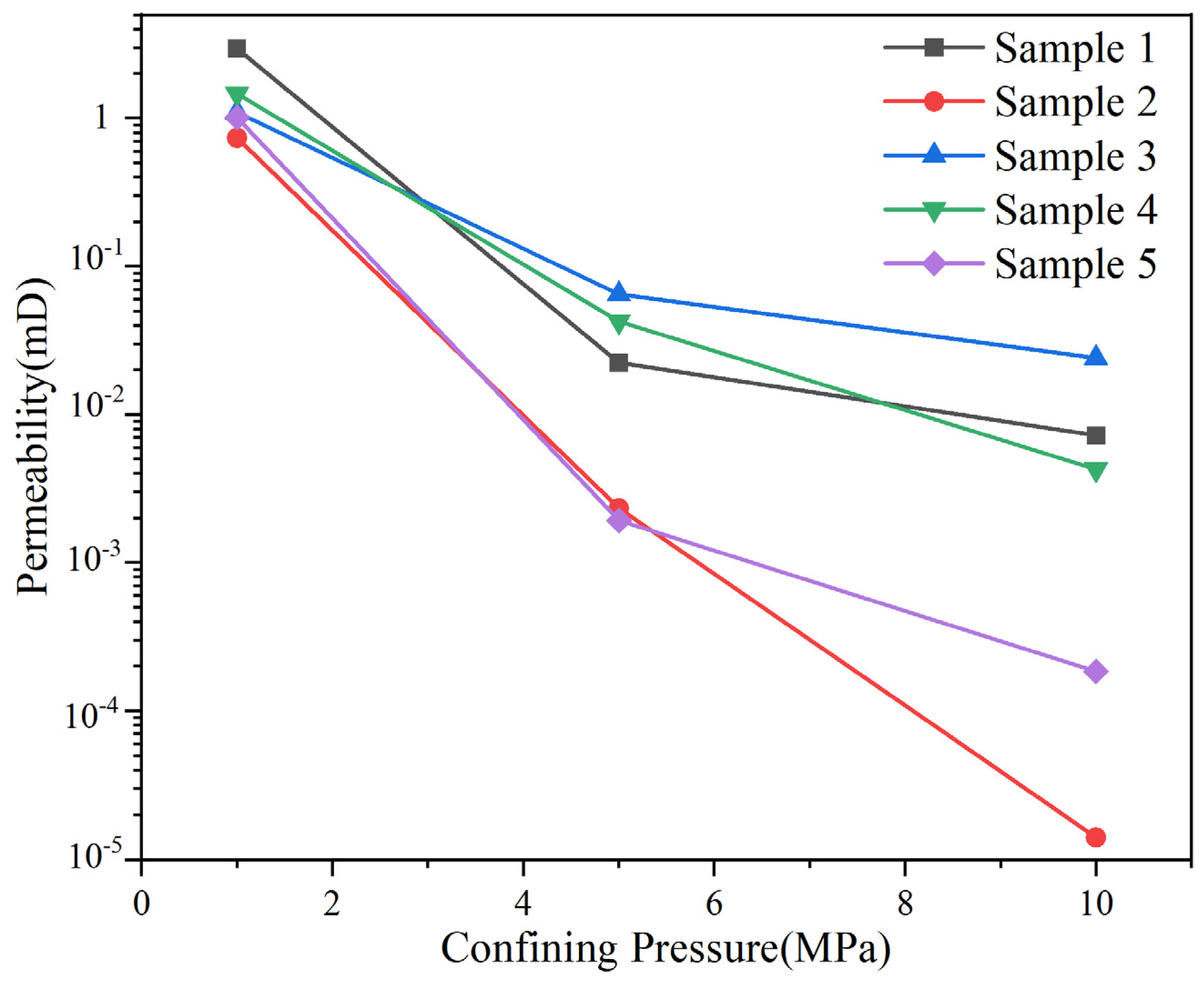
To obtain more accurate coal rock properties, the permeability and strength of coal rock samples were tested. Figure 2 illustrates the gas permeability of coal rock samples at various confining pressures. At a confining pressure of 1 MPa, the permeability averaged only 1.27 mD and dropped abruptly to below 0.1 mD with increasing confining pressure, mainly due to reduced fracture space and porosity, potentially decreasing by up to three orders of magnitude at a confining pressure of 10 MPa. This behavior is consistent with findings by Wu et al. [44] and Ya et al. [45], indicating significant stress sensitivity in deep coal rock permeability.
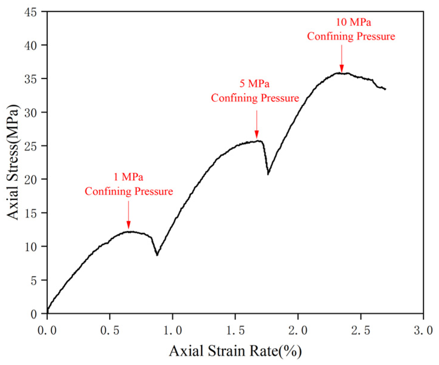
Figure 3 illustrates the stress–strain curves of coal rock under different confining pressures, showing elastic-plastic deformation and clear strain-weakening characteristics. As confining pressure increases, the peak pressure rises from 12.18 MPa at 1 MPa to 35.81 MPa at 10 MPa, indicating the high mechanical strength of coal rock. To assess shear strength, the maximum compressive strength was plotted against surrounding pressure using the Moore-Cullen criterion, resulting in a cohesion of 4.64 MPa and an internal friction angle of 33.7° (Figure 4), which indicate that while the coal rock possesses some shear strength, it is still lower than that of the top and bottom tuffs.
The dual-enhanced slurry used in this study is a brownish-yellow, polyphase polyurethane slurry with a density of 1.68 g/cm3 and a viscosity that can be adjusted between 50 and 500 mPa·s. The composition and physical parameters of the dual-enhanced slurry can be found in the literature [32,46]. In this study, we primarily considered slurry density, viscosity, and filtration coefficient, referring to Table 1.

2.3. Dual-Enhanced Stimulation Model for Deep CBM Reservoirs

This study establishes a two-dimensional model using field data to analyze the vertical expansion of fractures in a horizontal well. The model simulates a 100 × 100 m deep coal seam, with its upper boundary buried at 1900 m. It includes the upper boundary, lateral boundaries, the grouting point, and the target coal seam, as shown in Figure 5. The coal seam is divided into coal rock and natural beddings using Python 3.7 code that interacts with the Abaqus CAE. The injection point is positioned at the bottom center of the model to inject dual-enhanced slurry into the CBM reservoir while restricting boundary displacement and pore pressure in other directions. Given the finite-discrete element method’s greater network dependence compared to traditional finite element methods [47], a finer mesh of 1 m is used, resulting in 17,795 CPE4P cells to accurately characterize seepage. Additionally, cohesive cells are inserted between neighboring CPE4P cells through secondary development, yielding a final model with 35,590 COH2D4P cell grids, as illustrated in Figure 6, with cohesive cells near the injection point designated as the initial damage type.
This paper investigates the initiation and extension patterns of fractures under various engineering parameters, geological factors, and natural beddings. The engineering parameters include a grouting rate of 1.2–3.6 m3/min, based on previous reservoir stimulation studies [48,49], and slurry viscosity, determined by the controllable characteristics of the dual-enhanced slurry. Geological factors involve the ratio of lateral pressure coefficient to the strength of natural beddings and coal rocks. Peng et al. [42] noted that the deep CBM reservoir in the study area typically exhibits vertical stress greater than horizontal stress, with lateral pressure coefficients ranging from 0.7 to 0.9. The strength of natural strata, influenced by their structure, length, and strike, usually does not exceed 40% of the coal rock matrix strength [50], and in this study, the strata strength to coal rock strength ratio is set at 10–30%. To explore the impact of natural bedding characteristics on fracture extension, six groups of bedding parameters were established, with inclination angles of 10°, 30°, and 60°, and surface densities of 25, 81, and 225 beddings per 10,000 m. More detailed parameters can be found in Table 2.

3. Results and Discussion

3.1. Influence of Engineering Parameters on Diffusion Behavior of Polyurethane Slurry

As depicted in Figure 7, the slurry flows from the grouting point toward the natural bedding, following the direction of vertical geostress. After traveling along the bedding, the slurry turns and extends in the direction of the maximum principal stress, forming a curved slurry vein. Increasing the grouting rate significantly enhances both the propagation distance of the porous vein and the stimulated area of the reservoir. Notably, the expansion pattern of the slurry vein remains consistent across different grouting rates, with all instances showing a noticeable steering effect due to the presence of natural bedding.
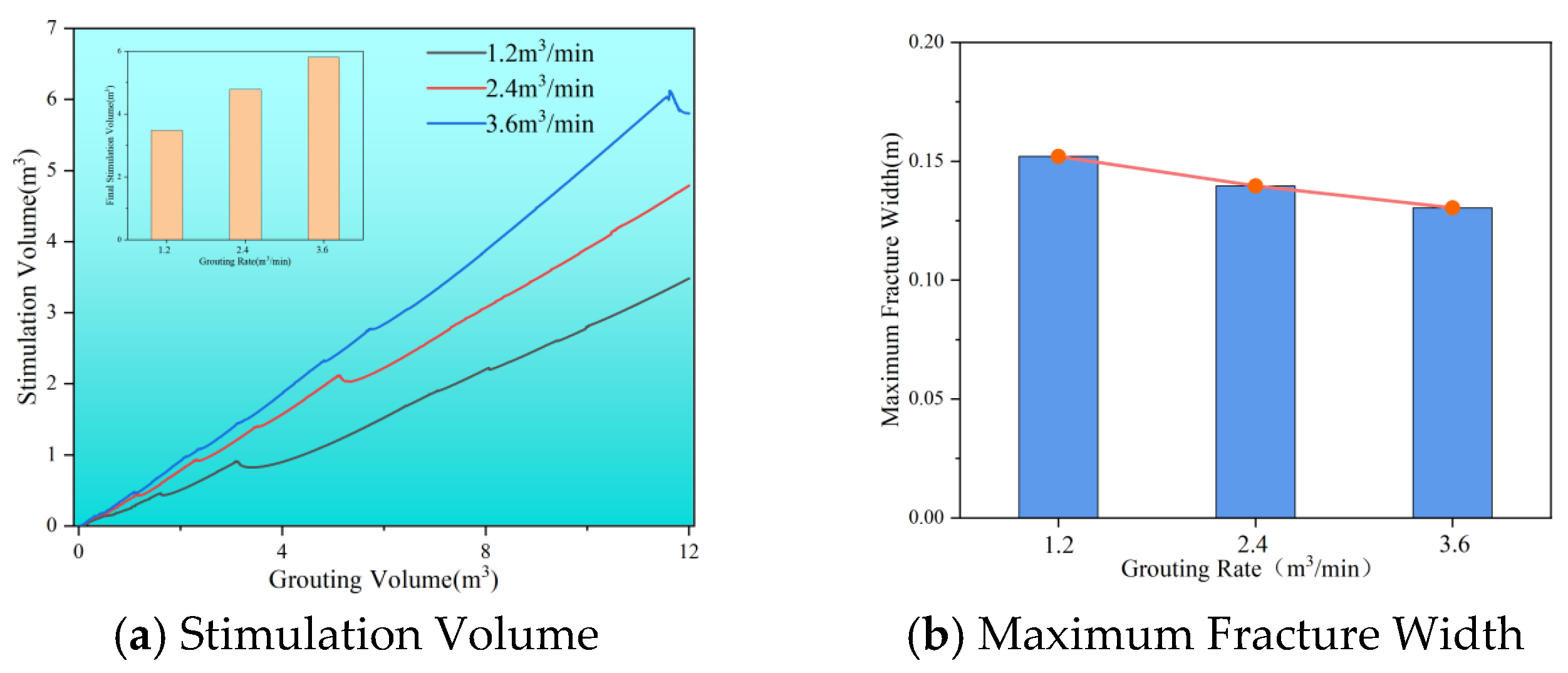
Figure 8 illustrates that raising the grouting rate from 1.2 m3/min to 3.6 m3/min increases the stimulation volume from 3.48 m3 to 5.80 m3, while the maximum width of the slurry vein decreases from 0.15 m to 0.13 m. This indicates that a higher grouting rate directs more slurry along the main fracture, resulting in less residual slurry between the cracks and a narrower maximum crack width. It is essential to note that the stimulation volume of the slurry does not always increase with the grouting process; at certain rates, it may actually decrease. This can happen because the seepage of the slurry into the reservoir can further reduce fracture width, ultimately impacting the overall stimulation volume.
As shown in Figure 9, increasing the viscosity of the slurry from 100 mPa·s to 500 mPa·s significantly alters the morphology of the slurry veins. At higher viscosity, the slurry penetrates the bedding and extends along it, leading to a change in direction. During the forward propagation, the slurry veins transition from multi-branch to single-branch, although the maximum length of propagation remains nearly the same. This behavior indicates that lower viscosity allows the slurry to move more easily through the coal rocks, reducing resistance and enabling forward movement and splitting in the direction of maximum stress. Conversely, as viscosity increases, the filtration loss coefficient decreases, which results in slower diffusion rates and a reduced tendency to form multi-branched veins.
As shown in Figure 10, the effective stimulation volume decreases as viscosity increases: 4.89 m3 at 100 mPa·s, 4.78 m3 at 300 mPa·s, and 4.61 m3 at 500 mPa·s. The maximum fracture width also varies with viscosity: 0.13 m at 100 mPa·s, 0.14 m at 300 mPa·s, and 0.12 m at 500 mPa·s. This trend indicates that higher viscosity makes it more difficult for the slurry to flow through the coal seam, increasing viscous resistance and reducing fluidity. Consequently, the slurry tends to be retained in fractures. For slurries at 100 and 500 mPa·s, the overall stimulation volume in the later stages of grouting shows a notable decline followed by a rise. In contrast, at 300 mPa·s, there is little fluctuation in late-stage stimulation volume. This behavior results from the dynamic balance between the slurry’s tangential flow and its filtration loss at both ends. Therefore, selecting the appropriate slurry viscosity is crucial for optimizing the stimulation effect.

3.2. Influence of Geologic Factors on Diffusion Behavior of Polyurethane Polymer Slurry

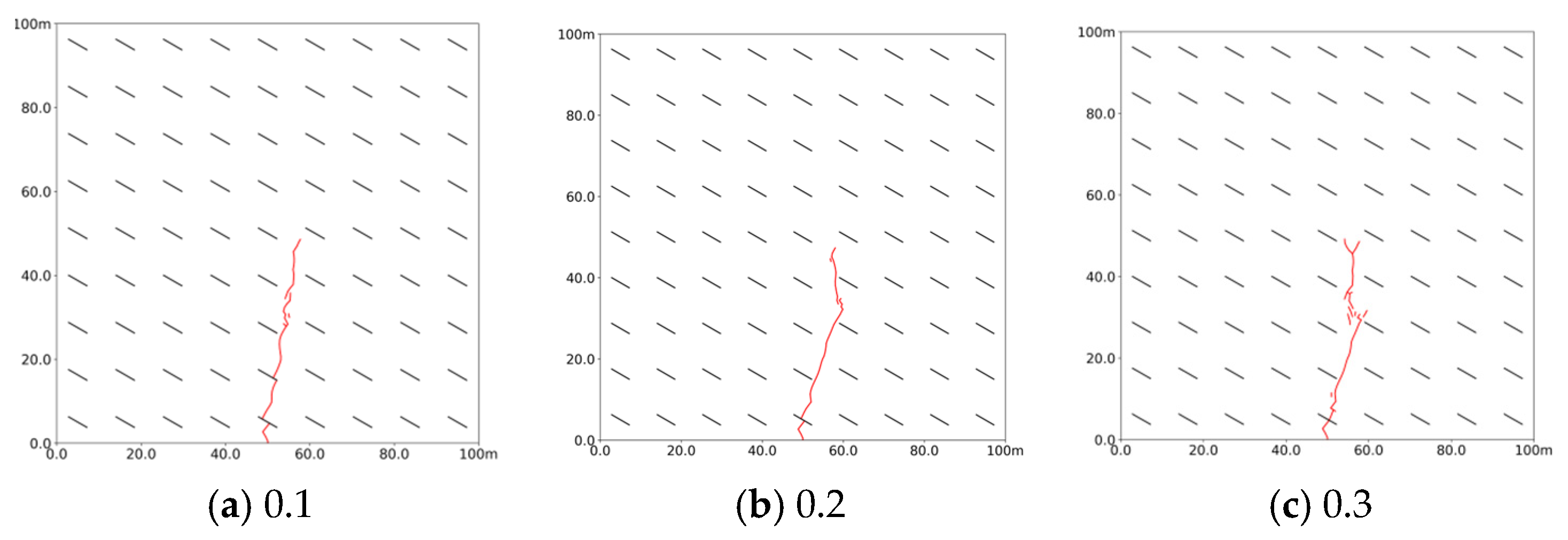
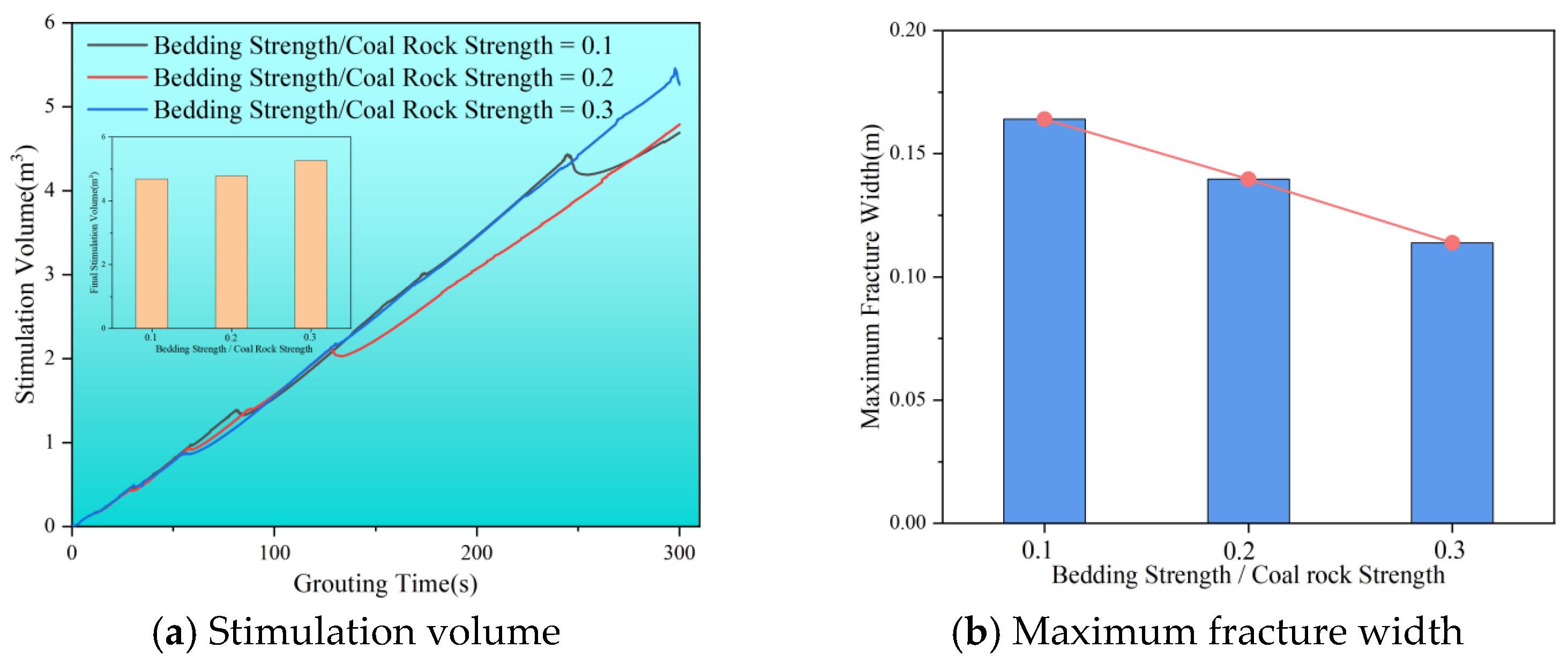
Figure 11 illustrates that the morphology of slurry veins becomes more complex as bedding strength increases. At a bedding strength to coal rock strength ratio of 0.1, the slurry flows easily along the bedding, expanding a certain distance. However, when this ratio rises to 0.2, the expansion distance decreases. At a ratio of 0.3, the slurry can penetrate the beddings and develop multiple branching veins. This indicates that the influence of natural bedding on the slurry’s expansion pattern only becomes significant when the bedding-to-coal rock strength ratio exceeds a threshold in the range 0.2–0.3. For a ratio ≤ 0.2, veins propagate along bedding; when a ratio ≥ 0.3, they tend to cross beddings and form branches. With the increase in bedding strength, the slurry’s spread length also increases, promoting the formation of multi-branched veins that extend radially and enhance the overall stimulation volume.
Figure 12a illustrates how stimulation volume changes over grouting time for various bedding strength conditions. As the ratio of bedding strength to coal rock strength rises from 0.1 to 0.2, the stimulation range remains relatively constant, suggesting that the ratio of bedding strength to coal rock strength has little effect on stimulation volume. Additionally, the number of fracture closures diminishes with increasing bedding strength. At a bedding strength to coal rock strength ratio of 0.1, the stimulation volume drops significantly twice, by 0.05 m3 and 0.23 m3. When the ratio increases to 0.2, there is only one notable decline of 0.08 m3. At a ratio of 0.3, the stimulation volume becomes nearly proportional to the grouting time, with no fracture closures occurring. This suggests that natural bedding strength plays a crucial role in influencing fracture closure effects. Zhou et al. (2020) [51] found that natural fractures complicate hydraulic fracturing, while Chen et al. (2018) [52] concluded that they increase the number of branching fractures and the stimulation volume. These studies highlight the important role of natural bedding in enhancing fracturing stimulation, consistent with the simulation results in this study. As shown in Figure 12b, the maximum width of the fracture decreases with increasing bedding strength, reaching only 0.11 m at a bedding strength to coal rock strength ratio of 0.3. This indicates that when the bedding strength exceeds a critical ratio relative to the coal matrix (≈0.2–0.3), its influence on the reservoir response increases markedly, promoting splitting rather than localized compaction. This transition enables a larger propagation radius and a greater final stimulation volume. Additionally, Zhu et al. (2009) [53] demonstrated that the fracturing pressure of coal reservoirs significantly decreases in the presence of natural beddings. Thus, when the bedding-to-matrix strength ratio increases (e.g., from ≈0.10 to ≈0.30), its influence on the coal seam’s mechanical response intensifies, making splitting damage more likely than localized compaction.
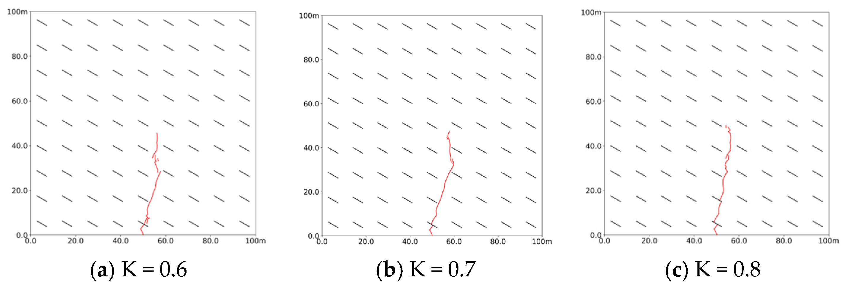
Geostress is a crucial factor influencing the direction and pattern of slurry diffusion. As shown in Figure 13, at a lateral stress coefficient of 0.6, the slurry vein expands along the vertical maximum principal stress without deflecting, but as the coefficient increases to 0.7 and then to 0.9, the slurry begins to flow along the bedding and extends its flow distance due to a diminishing stress difference between vertical and horizontal directions. This trend indicates that a lower lateral pressure coefficient leads to a greater disparity between the maximum and minimum principal stress, with the maximum principal stress exerting the strongest guiding effect on the slurry vein. Consequently, the slurry tends to spread along the vertical direction of the minimum principal stress, as it naturally flows towards areas of lower strength and stress concentration.
The magnitude of ground stress significantly impacts the diffusion radius and characteristics of the slurry vein. As illustrated in Figure 14, increasing the lateral pressure coefficient results in a decrease in stimulation volume while the maximum fracture width gradually increases. Under conditions of high stress difference, the slurry vein tends to exhibit a narrow width and larger volume. Additionally, as the lateral pressure coefficient rises, the stimulation volume continues to decrease, but fracture width expands. This indicates that a smaller lateral pressure coefficient leads to a greater disparity between vertical maximum principal stress and horizontal principal stress, making the reservoir more susceptible to splitting damage. Overall, geostress not only dictate the direction of slurry diffusion but also influence the diffusion radius and the length and width of slurry veins.

3.3. Influence of Bedding Characteristics on Diffusion Behavior of Polyurethane Polymer Slurry

As shown in Figure 15, the morphology of the slurry vein was analyzed at bedding densities of 25, 81, and 225 lines per 10,000 m3. At a density of 25 lines/10,000 m3, the slurry flows through two bedding layers, deflecting in the direction of bedding inclination and extending over 47 m. At 81 lines/10,000 m3, it initially flows through the first bedding layer near the injection port but quickly deviates from the direction of the maximum principal stress, preventing further passage through additional layers. Notably, around 30 m, the slurry steers between the bedding layers, which indicates that natural bedding redistributes stress during directional changes. In this region, the concentration of fluid pressure alters the local maximum principal stress direction. At a bedding density of 225 lines/10,000 m3, the slurry shifts from expanding along the bedding to penetrating directly into it, forming fine branching veins and experiencing nearly 90° deflections twice. Guo et al. [54] found that new fractures formed when hydraulic fractures pass through natural beddings always extend in the direction of maximum principal stress. This stress direction is influenced by the reservoir’s initial stress and fluid pressure, meaning that more natural beddings result in more complex stress distribution, affecting fluid flow direction. Additionally, local stress concentration from fluid flow controls reservoir stress redistribution, making the steering effect of natural bedding on hydraulic fractures a result of the interaction between stress and seepage fields.
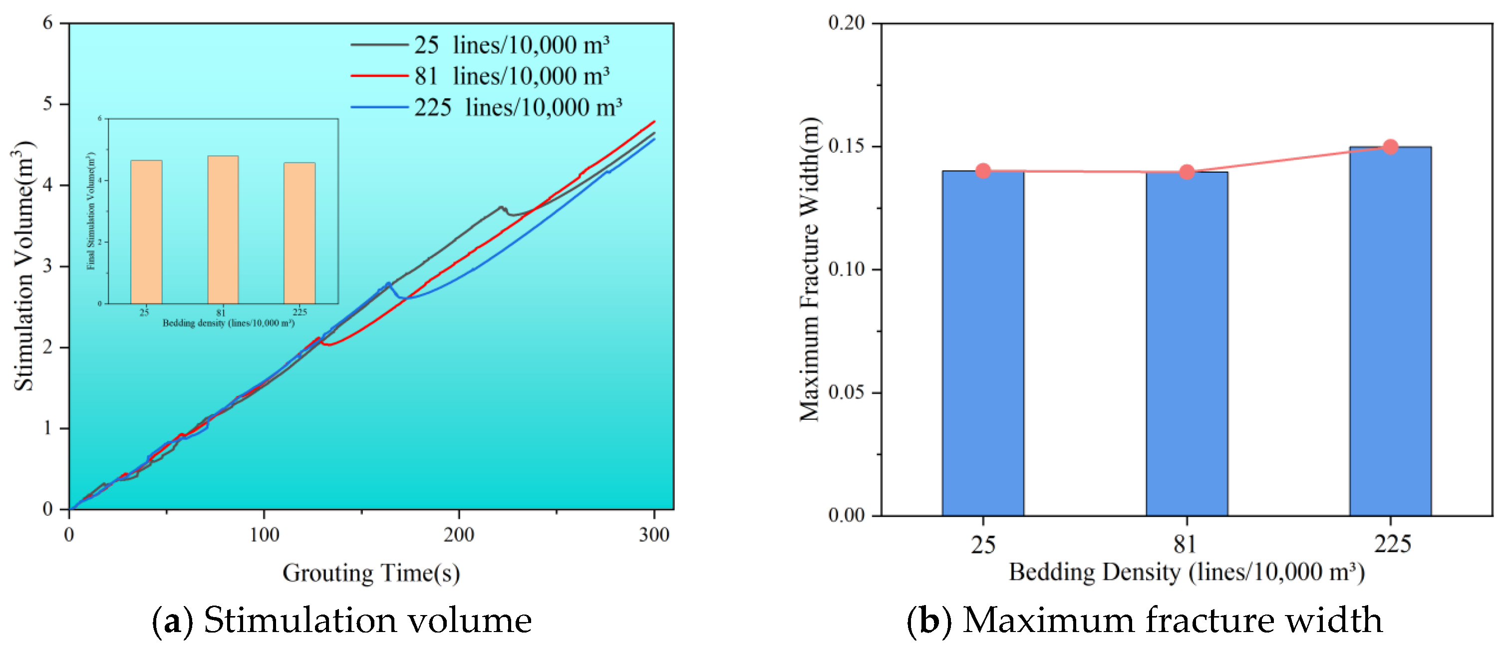
Figure 16 shows the stimulation volume change curve during grouting at different bedding densities. The final stimulation volume is approximately the same across all densities, around 4.65 m3. However, the timing of fracture closure varies, with the most significant volume reduction occurring at 130 s, 164 s, and 220 s. This variation is linked to how the maximum principal stress responds to bedding density and the timing of reservoir stress redistribution, affecting when fractures experience maximum effective closure pressure. Figure 16b illustrates the maximum width of cracks at different bedding densities. When the bedding density increases from 25 to 81 lines/10,000 m3, the maximum fracture width remains nearly constant. This could be due to the limited number of bedding layers the slurry vein can pass through at lower densities of 25 lines/10,000 m3, resulting in minimal influence on slurry vein width. Conversely, at higher densities of 225 lines/10,000 m3, the more complex stress distribution can lead to greater stress concentration during grouting, increasing crack opening and thickening the slurry vein. Additionally, local stress changes from steering further promote fracture extension, contributing to an increase in vein thickness in those areas.
Figure 17 illustrates that the deflection of slurry veins increases significantly with the bedding inclination angle. At a 10° angle, the slurry veins expand almost vertically, with many small branch veins visible. When the bedding inclination is raised to 30°, the slurry veins deflect towards the direction of the maximum principal stress at that angle. At a 60° bedding inclination, the veins become nearly parallel to the bedding direction. This indicates that higher bedding angles lead to more deflected slurry veins, while lower angles result in nearly vertical expansion.
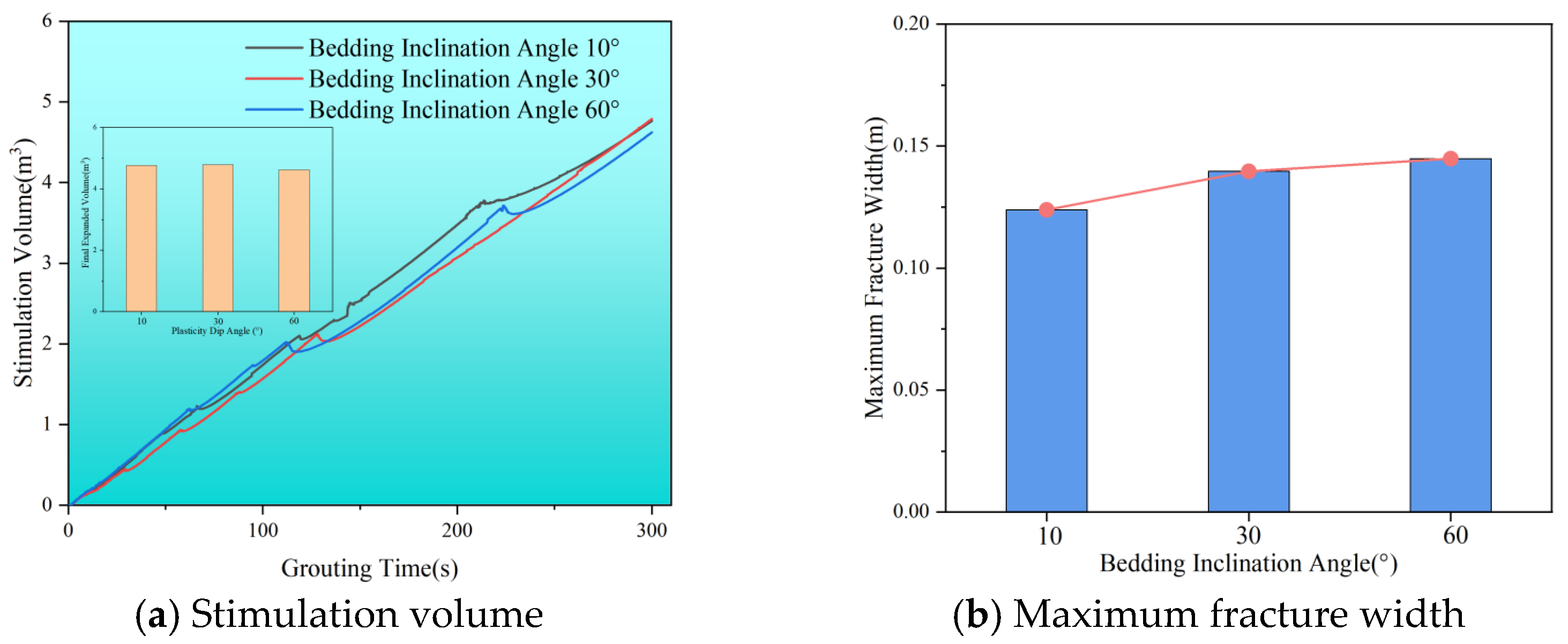
Figure 18a indicates that as bedding inclination angles increase, the stimulation volume remains relatively constant, suggesting that bedding inclination primarily influences the overall morphology of the slurry veins rather than stimulation volume. Figure 18b shows the maximum width of fractures at varying bedding angles. As the angle increases from 10° to 60°, the maximum fracture width grows from 0.12 m to 0.14 m, resulting in noticeably thicker slurry veins. Additionally, the thickness of the slurry vein near the grouting port increases rapidly at the beginning of grouting but slows down later on. The thickness also rises with higher bedding inclination angles. However, the overall stimulation range of the slurry remains consistent, suggesting that the flow path for the slurry is shorter at higher bedding inclinations.

3.4. Analysis of Dual-Enhanced Stimulation Process

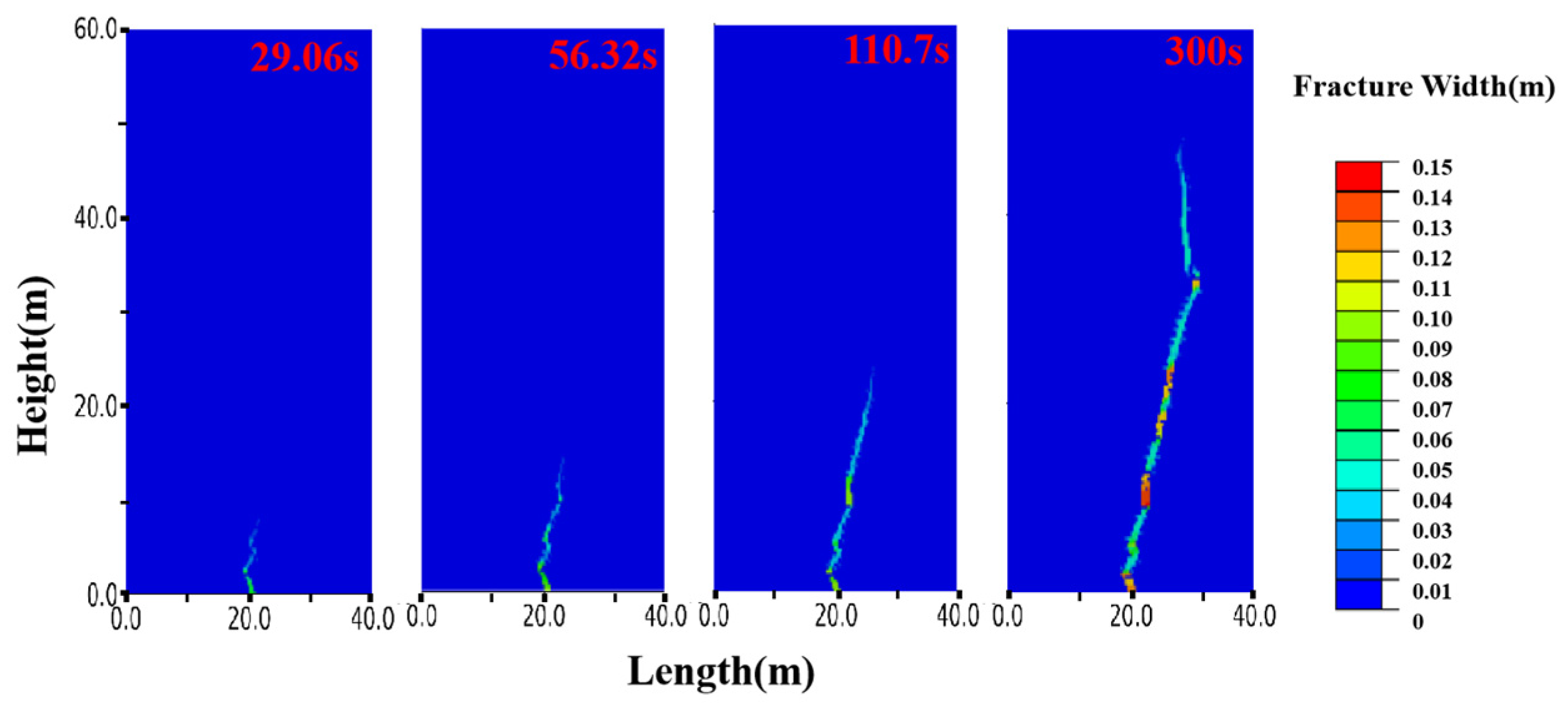
To further investigate the slurry diffusion process, Figure 19 presents the cloud diagram of displacement changes for Run 2. During the first 300 s of injection, the slurry veins experience significant deflection five times, likely due to localized fluid stress concentration at the slurry tip and the diffusion direction toward the maximum principal stress in the reservoir. The color of the slurry vein indicates crack width, with blue representing narrower areas and red indicating thicker regions. This shows that the split-formed slurry vein is nonuniform: it is widest and shortest near the grouting port and narrows and elongates toward the fracture tip, producing a wedge-shaped geometry.
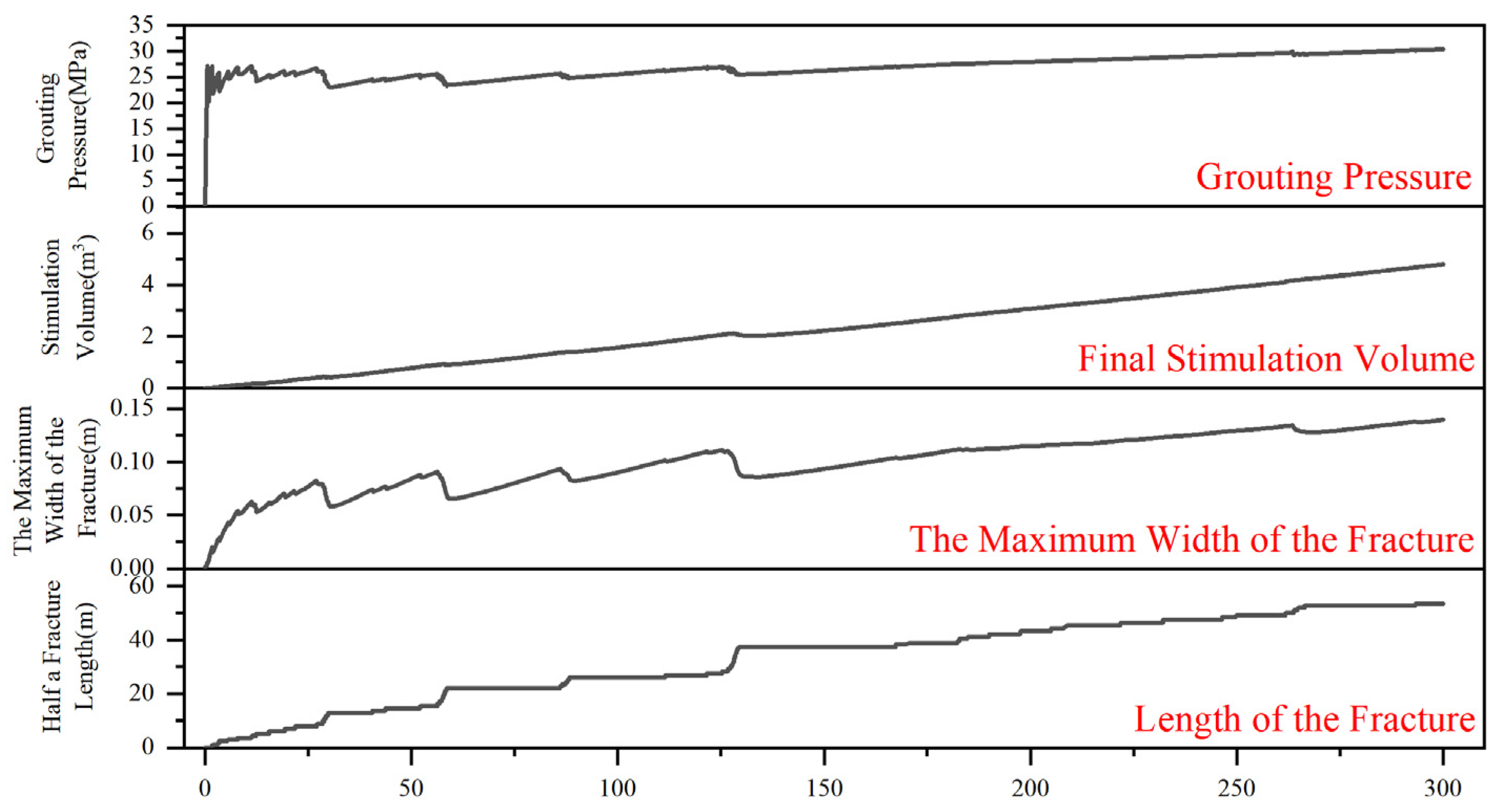
As shown in Figure 20, the grouting process comprises three stages: slurry accumulation, splitting grouting, and compaction grouting. In Stage 1, pressure rises rapidly but remains below the fracturing threshold; the slurry accumulates near the injection point, compresses the surrounding coal, and fills pores, elevating pore pressure without creating new fractures. When the grouting pressure approaches ~27 MPa (t ≈ 1–15 s), near-wellbore pores become saturated and the stress at the fracture tip exceeds the damage threshold. Fracture initiation and intermittent propagation then produce pressure oscillations: each advance releases stress, followed by re-pressurization. This pressure cycling characterizes Stage 2 (splitting grouting). A thin, narrow vein forms at the propagating tip, and the first three deflections occur during this phase, consistent with the slurry spreading morphology in Figure 20.
From 15 to 300 s, the grouting pressure stabilizes around 30 MPa, resembling typical fracturing operations. This stability reflects a dynamic balance among leak-off, fracture-volume growth, and injection rate, allowing gradual lateral spreading. Although the pressure remains above the splitting threshold, fractured coal particles accumulate at the slurry front, reducing porosity and raising local fracture resistance. As a result, further fracture extension becomes difficult near ~30 MPa, and compaction grouting becomes dominant. The expansion-volume curve continues to rise while fracture length grows in steps, indicating local accumulation rather than continuous advance. Fluctuations in maximum fracture width suggest partial closure due to the balance between injection and leak-off. Two additional turns occur during the compaction phase, implying uneven in situ stress near the slurry front; these heterogeneities generate local stress concentrations that steer the veins. Each redirection requires additional energy and further impedes propagation.
In conclusion, both splitting and compaction damage occur during dual-enhanced stimulation, with stress concentration at the fracture tips and reservoir stress redistribution being key factors in the slurry vein’s direction.

3.5. Analysis of the Main Controlling Factors of Splitting Pressure

The analysis of grouting pressure under various conditions—such as grouting rates, slurry viscosity, natural bedding strength, lateral pressure coefficient, bedding density, and bedding inclination—aims to identify the primary factors influencing the porous slurry veins propagation. Figure 21 illustrates the grouting pressure curves across different scenarios. Notably, fluctuations in grouting pressure are most prominent during the pre-grouting phase, as the reservoir begins to split and the slurry accumulates in its pore spaces, applying stress to surrounding coal rocks. Once this stress surpasses the fracture strength of the coal rock, a sudden release of pressure occurs, allowing the slurry to propagate forward and create fractures under high fluid pressure. This leads to a repetitive cycle of buildup, release, and filling, establishing seepage channels for slurry expansion. In the mid to late stages of grouting, pressure fluctuations significantly decrease, stabilizing around 30 to 35 MPa, which indicates that the reservoir is experiencing compaction damage. Notably, some runs show a marked reduction in pressure during the late grouting phase, suggesting that the slurry tip pressure has surpassed the fracturing pressure, leading to additional splitting of the reservoir. In this phase, both splitting and compaction grouting modes are present, though compaction damage predominates. The findings reveal that the grouting rate and lateral pressure coefficient are the most influential factors affecting splitting pressure, with variance values of 5.10 and 2.62, respectively. As the grouting rate increases from 1.2 m3/min to 3.6 m3/min, the initiation pressure rises from 26.28 to 31.44 MPa. This demonstrates that higher grouting rates significantly increase fluid pressure, allowing it to quickly exceed the reservoir’s destructive strength. Consequently, this pressure sensitivity shortens the splitting time, as higher injection rates enable faster filling of the reservoir pores. Therefore, adjusting the grouting rate strategically can effectively reduce splitting pressure while enhancing the diffusion range of the slurry within the reservoir.

4. Conclusions

This study presents a novel dual-increasing stimulation method for deep CBM reservoirs. Using the tested mechanical strength and gas permeability of coal rock cores, the finite-discrete element method simulates the propagation of porous slurry veins during dual-increasing stimulation within the CBM reservoir. The research focuses on how engineering parameters, geological factors, and bedding features influence the propagation pattern of slurry veins and the primary factors affecting the fracture initiation pressure in the reservoir. The following conclusions were drawn:
  • As the grouting rate increases, the volume of dual-enhanced stimulation also rises, resulting in a wider maximum width of the slurry vein. Specifically, at a grouting rate of 3.6 m3/min, the volume of dual-enhanced stimulation can reach 5.8 m3, with the maximum width of the slurry vein measuring approximately 0.15 m. When the slurry viscosity is low, the slurry tends to expand into multiple veins. However, as the viscosity increases, the volume of dual-enhanced stimulation decreases, while the maximum width of the slurry veins expands further. This trend indicates that compaction grouting is more likely to occur at higher viscosities.
  • When bedding strength is high, the slurry tends to penetrate through the beddings. In contrast, a lower bedding strength allows the slurry to expand along the bedding, which decreases the maximum width of the slurry vein as the bedding strength increases. Additionally, as the lateral pressure coefficient rises, the volume of dual-enhanced stimulation decreases, making it more likely for the slurry to expand along the beddings. Natural bedding promotes directional flow; denser bedding results in more pronounced directional changes, creating a more complex network of slurry veins. As the angle of inclination increases, the slurry veins are more likely to change direction. At low bedding angles of 10°, the slurry expands almost vertically, while the maximum width of the slurry vein increases with steeper bedding inclinations.
  • During the grouting process, the directional flow of the slurry may be caused by localized stress concentration at the tip of the slurry, leading to its release along the direction of the maximum principal stress in the reservoir. Pressure fluctuations primarily occur in the early stages of grouting, when the slurry continuously accumulates, releases, and fills within the reservoir, resulting in fracturing damage. In the later stages of grouting, the pressure stabilizes around 30 MPa, with compaction damage becoming predominant. Under these reservoir conditions, both fracturing and compaction grouting modes coexist, with fracturing grouting being more prevalent initially and compaction grouting taking precedence later. Furthermore, the grouting rate significantly affects the fracturing pressure of the reservoir; as the grouting rate increases, the time to achieve fracturing decreases, and the fracturing pressure increases.

Author Contributions

Conceptualization, X.W.; Formal analysis, X.W., J.W. and S.Q.; Investigation, S.Q. and G.Z.; Methodology, X.W.; Supervision, X.W.; Validation, F.Z.; Writing—original draft, F.Z. and G.Z.; Writing—review and editing, F.Z., J.W., S.Q., B.L. and G.Z. All authors have read and agreed to the published version of the manuscript.

Funding

The financial support received from the National Natural Science Foundation of China (Nos. 42202347 and 51991364).

Data Availability Statement

Data is contained within the article.

Acknowledgments

The authors extend their gratitude to Wu Xiaoli (from Scientific Compass www.shiyanjia.com) for providing invaluable assistance with the strength tests. The coal rock samples in this study were procured from Natural Gas Research Institute of Yanchang Petroleum (Group) Co., Ltd.

Conflicts of Interest

Xiangzeng Wang, Fengsan Zhang and Jinqiao Wu were employed by the company Yanchang Petroleum (Group) Co., Ltd. The remaining authors declare that the research was conducted in the absence of any commercial or financial relationships that could be construed as a potential conflict of interest.

References

  1. Burnham, A.K.; McConaghy, J.R. Comparison of the Acceptability of Various Oil Shale Processes. In Proceedings of the 26th Oil Shale Symposium, Golden, CO, USA, 16–20 October 2006. [Google Scholar]
  2. Esen, O.; Fişne, A. A comprehensive study on methane adsorption capacities and pore characteristics of coal seams: Implications for efficient coalbed methane development in the Soma Basin, Türkiye. Rock Mech. Rock Eng. 2024, 57, 6355–6375. [Google Scholar] [CrossRef]
  3. Lei, Q.; Wang, H.-y.; Zhao, Q.; Liu, D. Status analysis and advices on exploration and development of unconventional hydrocarbon resources. Nat. Gas Ind. 2008, 28, 7–10. [Google Scholar]
  4. Song, Y.; Zhang, X.; Liu, S.; Song, Y.; Zhang, X.; Liu, S. Status Quo and Research of CBM Exploration and Development. In Coalbed Methane in China; Geological Theory and Development; Springer: Singapore, 2021; pp. 1–12. [Google Scholar]
  5. Yao, G.; Wang, J. A glimpse of coalbed methane production overseas and reflections on accelerating coalbed methane development in China. Sino-Glob. Energy 2010, 15, 25–33. [Google Scholar]
  6. Xie, H.; Gao, F.; Ju, Y.; Gao, M.; Zhang, R.; Gao, Y.; Liu, J.; Xie, L. Quantitative definition and investigation of deep mining. J. China Coal Soc. 2015, 40, 1–10. [Google Scholar]
  7. Zhang, S.; Tang, S.; Tang, D.; Pan, Z.; Yang, F. The characteristics of coal reservoir pores and coal facies in Liulin district, Hedong coal field of China. Int. J. Coal Geol. 2010, 81, 117–127. [Google Scholar] [CrossRef]
  8. Liu, C.; Zhu, J.; Che, C.; Yang, H.; Fan, M. Methodologies and results of the latest assessment of coalbed methane resources in China. Nat. Gas Ind. 2009, 29, 130–132. [Google Scholar]
  9. Geng, M.; Chen, H.; Chen, Y.; Zeng, L.; Chen, S.; Jiang, X. Methods and results of the fourth round national CBM resources evaluation. Coal Sci. Technol. 2018, 36, 64–68. [Google Scholar]
  10. Shen, J.; Qin, Y.; Fu, X.; Chen, G.; Run, C. Properties of deep coalbed methane reservoir-forming conditions and critical depth discussion. Nat. Gas Geosci. 2014, 25, 1470–1476. [Google Scholar]
  11. Li, S.; Tang, D.; Xu, H.; Tao, S.; Shao, G.; Ren, P. Evolution of physical differences in various buried depth of coal reservoirs under constraint of stress. Acta Pet. Sin. 2015, 36, 68–75. [Google Scholar]
  12. Ye, J.-p.; Zhang, S.-r.; Ling, B.-c.; Zheng, G.-q.; Wu, J.L. Study on variation law of coalbed methane physical property parameters with seam depth. Coal Sci. Technol. 2014, 42, 35–39. [Google Scholar]
  13. Li, S.; Tang, D.; Xu, H.; Tao, S. Progress in geological researches on the deep coalbed methane reservoirs. Earth Sci. Front. 2016, 23, 10. [Google Scholar]
  14. Zhong, L.; Zheng, Y.; Yun, Z.; Lei, C.; Zhang, H. The adsorption capability of coal under integrated influence of temperature and pressure and predicted content quantity of coal bed gas. Mei T’an Hsueh Pao (J. China Coal Soc.) 2002, 27, 581–585. [Google Scholar]
  15. Pan, Z.; Wood, D.A. Coalbed methane (CBM) exploration, reservoir characterisation, production, and modelling: A collection of published research (2009–2015). J. Nat. Gas Sci. Eng. 2015, 26, 1472–1484. [Google Scholar] [CrossRef]
  16. Yuan, L.; Lin, B.Q.; Yang, W. Research progress and development direction of gas control with mine hydraulic technology in China coal mine. Coal Sci. Technol. 2015, 43, 45–49. [Google Scholar]
  17. Lv, H.; Cheng, Z.; Xie, F.; Pan, J.; Liu, F. Study on hydraulic fracturing prevention and control of rock burst in roof of deep extra-thick coal seam roadway group. Sci. Rep. 2024, 14, 29537. [Google Scholar] [CrossRef]
  18. Gang, C. The adsorption characteristics and affecting factors of deep low-rank coal in Cainan area of Junggar basin. Coal Geol. Explor. 2016, 44, 50–54. [Google Scholar]
  19. Hu, S.; Wang, X.; Cao, Z.; Li, J.; Cong, D.; Xu, Y. Formation conditions and exploration direction of large and medium gas reservoirs in the Junggar Basin, NW China. Pet. Explor. Dev. 2020, 47, 266–279. [Google Scholar] [CrossRef]
  20. Shen, P.; Lv, S.; Li, G.; Ren, B.; Bai, J.; Jia, J.; Chen, Z. Hydraulic fracturing technology for deep coalbed methane horizontal wells: A case study in North Changzhi area of Qinshui Basin. J. China Coal Soc. 2021, 46, 2488–2500. [Google Scholar]
  21. Sun, P.; Liu, H.; Chao, H.; Wang, Y. Exploration direction of coalbed methane in low-rank coals. Nat. Gas Ind. 2008, 28, 19–22. [Google Scholar]
  22. Wu, C.; Qin, Y.; Fu, X. Macroscopic dynamic energies for the formation of coalbed gas reservoirs and their geological evolution—A case study from Qinshui Basin in Shanxi Province. Earth Sci. Front. 2005, 12, 299–308. [Google Scholar]
  23. Li, Y.; Jia, D.; Liu, J.; Fu, C.; Ai, C. The calculation method based on the equivalent continuum for the fracture initiation pressure of fracturing of coalbed methane well. J. Pet. Sci. Eng. 2016, 146, 909–920. [Google Scholar] [CrossRef]
  24. Jiang, T.; Zhang, J.; Huang, G. Experimental study of fracture geometry during hydraulic fracturing in coal. Rock Soil Mech. 2018, 39, 3677–3684. [Google Scholar]
  25. Zangeneh, N.; Eberhardt, E.; Bustin, R. Application of the distinct-element method to investigate the influence of natural fractures and in-situ stresses on hydrofrac propagation. In Proceedings of the ARMA US Rock Mechanics/Geomechanics Symposium, Chicago, IL, USA, 24–27 June 2012; p. ARMA-2012-223. [Google Scholar]
  26. Wang, T.; Hu, W.; Elsworth, D.; Zhou, W.; Zhou, W.; Zhao, X.; Zhao, L. The effect of natural fractures on hydraulic fracturing propagation in coal seams. J. Pet. Sci. Eng. 2017, 150, 180–190. [Google Scholar] [CrossRef]
  27. Ma, G.; Zhang, F.; Liu, X.; Feng, D. Experimental study on hydraulic fracture propagation in fractured reservoir. J. Min. Saf. Eng. 2017, 34, 993999. [Google Scholar]
  28. Liu, X.; Ding, Y.; Luo, P.; Liang, L. Influence of natural fracture on hydraulic fracture propagation. Spec. Oil Gas Reserv. 2018, 2, 148–153. [Google Scholar]
  29. Nikam, A.; Awoleke, O.O.; Ahmadi, M. Modeling the interaction between natural and hydraulic fractures using 3D finite-element analysis. SPE Prod. Oper. 2019, 34, 703–724. [Google Scholar] [CrossRef]
  30. Li, B.; Ma, X.; Zhang, G.; Guo, W.; Xu, T.; Yuan, Y.; Sun, Y. Enhancement of gas production from natural gas hydrate reservoir by reservoir stimulation with the stratification split grouting foam mortar method. J. Nat. Gas Sci. Eng. 2020, 81, 103473. [Google Scholar] [CrossRef]
  31. Desai, A.; Auad, M.L.; Shen, H.; Nutt, S.R. Mechanical behavior of hybrid composite phenolic foam. J. Cell. Plast. 2008, 44, 15–36. [Google Scholar] [CrossRef]
  32. Sun, Y.; Shen, Y.; Zhang, G.; Li, B.; Huang, F.; Qi, Y.; Shan, H.; Jin, F. Performance of dual-increasing stimulation slurry and its consolidating body for submarine hydrate reservoir. J. China Univ. Pet. (Ed. Nat. Sci.) 2022, 46, 1–10. [Google Scholar]
  33. Wang, X.; Sun, Y.; Guo, W.; Chen, H.; Peng, S. An environmental-benign method to enhance hydrate production in clayey silty reservoir via splitting grouting. J. Clean. Prod. 2024, 449, 141780. [Google Scholar] [CrossRef]
  34. Yu, Y.; Liu, J.; Li, B.; Sun, Y. Analysis of the hydraulic fracturing mechanism and fracture propagation law with a new extended finite element model for the silty hydrate reservoir in the South China Sea. J. Nat. Gas Sci. Eng. 2022, 101, 104535. [Google Scholar] [CrossRef]
  35. Munjiza, A.; Owen, D.; Bicanic, N. A combined finite-discrete element method in transient dynamics of fracturing solids. Eng. Comput. 1995, 12, 145–174. [Google Scholar] [CrossRef]
  36. Donzé, F.V.; Richefeu, V.; Magnier, S.-A. Advances in discrete element method applied to soil, rock and concrete mechanics. Electron. J. Geotech. Eng. 2009, 8, 44. [Google Scholar]
  37. Zhu, H.; Tang, X.; Liu, Q.; Li, K.; Xiao, J.; Jiang, S.; McLennan, J.D. 4D multi-physical stress modelling during shale gas production: A case study of Sichuan Basin shale gas reservoir, China. J. Pet. Sci. Eng. 2018, 167, 929–943. [Google Scholar] [CrossRef]
  38. Liu, Z.; Pan, Z.; Li, S.; Zhang, L.; Wang, F.; Han, L.; Zhang, J.; Ma, Y.; Li, H.; Li, W. Study on the effect of cemented natural fractures on hydraulic fracture propagation in volcanic reservoirs. Energy 2022, 241, 122845. [Google Scholar] [CrossRef]
  39. Park, K.; Paulino, G.H. Cohesive zone models: A critical review of traction-separation relationships across fracture surfaces. Appl. Mech. Rev. 2011, 64, 060802. [Google Scholar] [CrossRef]
  40. Ma, C.; Dong, C.; Luan, G.; Lin, C.; Liu, X.; Elsworth, D. Types, characteristics and effects of natural fluid pressure fractures in shale: A case study of the Paleogene strata in Eastern China. Pet. Explor. Dev. 2016, 43, 634–643. [Google Scholar] [CrossRef]
  41. Xiong, D.; He, J.; Ma, X.; Qu, Z.; Guo, T.; Ma, S. Fracturing simulation with different perforation positions at deep coal seam and roof/floor rock—Case study at the No. 8 deep coal seam of a gas field in the Ordos basin. J. China Coal Soc. 2024, 49, 4897–4914. [Google Scholar]
  42. Peng, W.; Mi, H.; Xu, L.; Wu, J. Fracability evaluation and classification of deep coal reservoirs in the Shenfu block. Coal Sci. Technol. 2025, 53, 238–247. [Google Scholar]
  43. Wan, Y.; Wang, Z.; Han, S.; Qiao, Y.; Gao, H. Geological characteristics and resource potential of deep coalbed methane accumulation in Yan’an Gas Field, southeastern margin of Ordos Basin. Nat. Gas Geosci. 2024, 35, 1724–1739. [Google Scholar]
  44. Wu, S.; Tang, D.; Li, S.; Wu, H.; Hu, X.; Zhu, X. Effects of geological pressure and temperature on permeability behaviors of middle-low volatile bituminous coals in eastern Ordos Basin, China. J. Pet. Sci. Eng. 2017, 153, 372–384. [Google Scholar] [CrossRef]
  45. Meng, Y.; Li, Z. Experimental study on the porosity and permeability of coal in net confining stress and its stress sensitivity. J. China Coal Soc. 2015, 40, 154–159. [Google Scholar]
  46. Qi, Y.; Sun, Y.; Li, B.; Liu, X.; Zhang, G. Fracture Initiation and Slurry Diffusion in Marine Hydrate Reservoirs during Dual-Enhanced Stimulation. Energy Fuels 2025, 39, 6849–6864. [Google Scholar] [CrossRef]
  47. Chandra, N.; Li, H.; Shet, C.; Ghonem, H. Some issues in the application of cohesive zone models for metal–ceramic interfaces. Int. J. Solids Struct. 2002, 39, 2827–2855. [Google Scholar] [CrossRef]
  48. Jiang, T.; Zhang, J.; Wu, H. Experimental and numerical study on hydraulic fracture propagation in coalbed methane reservoir. J. Nat. Gas Sci. Eng. 2016, 35, 455–467. [Google Scholar] [CrossRef]
  49. Zou, J.; Chen, W.; Yuan, J.; Yang, D.; Yang, J. 3-D numerical simulation of hydraulic fracturing in a CBM reservoir. J. Nat. Gas Sci. Eng. 2017, 37, 386–396. [Google Scholar] [CrossRef]
  50. Wang, P.-t.; Yang, T.-h.; Yu, Q.-l.; Shi, W.-h. Uniaxial compression test and numerical simulation of stratified biotite granulite. J. Northeast. Univ. (Nat. Sci.) 2015, 36, 1633–1637. [Google Scholar]
  51. Zhou, X.; Yong, R.; Fan, Y.; Zeng, B.; Song, Y.; Guo, X.; Zhou, N.; Duan, X.; Zhu, Z. Influence of natural fractures on fracturing of horizontal shale gas wells and process adjustment. China Pet. Explor. 2020, 25, 94–104. [Google Scholar] [CrossRef]
  52. Chen, X.; Zhang, G.; Yang, K.; Xu, D. Numerical simulation on volumetric fracturing for shale gas reservoir considering natural fractures. China Sci. 2018, 13, 286–290. [Google Scholar]
  53. Zhu, B.; Tang, S.; Yan, Z.; Zhang, J. Effects of crustal stresses and natural fractures on fracture pressure of coal reservoirs. J. China Coal Soc. 2009, 34, 1199–1202. [Google Scholar]
  54. Guo, J.; Wang, Y. Mechanism of natural fracture reactivation and propagation by hydraulic fracture. J. Eng. Geol. 2018, 26, 1523–1533. [Google Scholar]
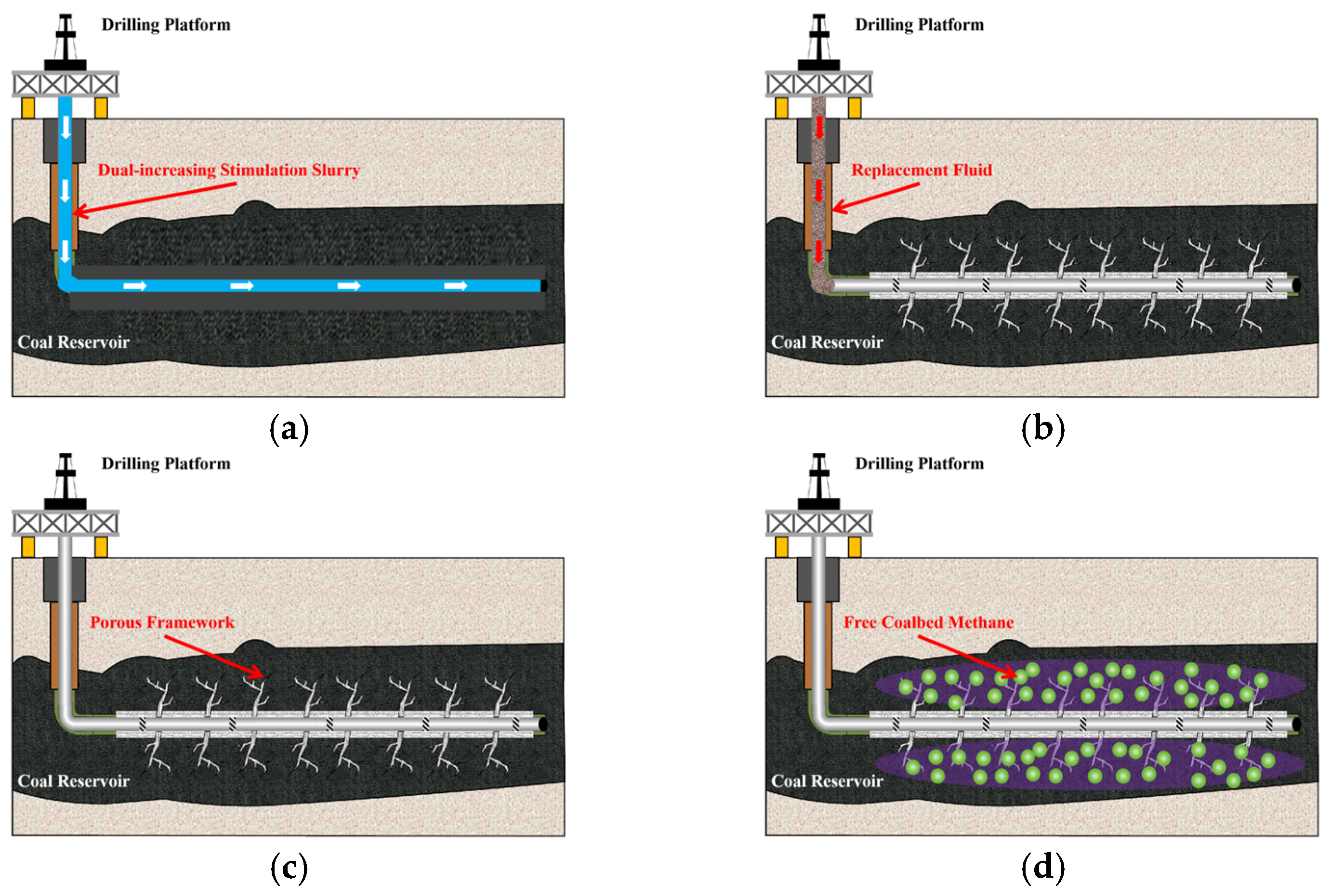
Figure 1. Dual-enhanced stimulation process of horizontal wells for CBM. (a) Injection of slurry for fracturing stimulation. (b) Injection of displacing fluid to replace the slurry. (c) Slurry solidification to form porous slurry veins. (d) Depressurization for CBM extraction.
Polymers 17 02513 g001
Figure 2. Permeability of coal cores under different confining pressures.
Polymers 17 02513 g002
Figure 3. Triaxial stress–strain curve of coal cores.
Polymers 17 02513 g003
Figure 4. Mohr stress circle of coal cores.
Polymers 17 02513 g004
Figure 5. Split grouting model and mesh schematic.
Polymers 17 02513 g005
Figure 6. Model mesh schematic.
Polymers 17 02513 g006
Figure 7. Propagation morphology of porous slurry veins at different injection rates. (Red lines denote slurry veins) (a) 1.2 m3/min. (b) 2.4 m3/min. (c) 3.6 m3/min.
Polymers 17 02513 g007
Figure 8. Stimulation volume and maximum fracture width at different injection rates. (a) Stimulation Volume. (b) Maximum Fracture Width.
Polymers 17 02513 g008
Figure 9. Propagation morphology of porous slurry veins with different slurry viscosities. (a) 100 mPa·s. (b) 300 mPa·s. (c) 500 mPa·s.
Polymers 17 02513 g009
Figure 10. Stimulation volume and maximum fracture width at different slurry viscosities. (a) Stimulation volume. (b) Maximum fracture width.
Polymers 17 02513 g010
Figure 11. Propagation morphology of porous slurry veins with varying ratios of bedding strength to coal rock strength. (Red lines denote slurry veins) (a) 0.1. (b) 0.2. (c) 0.3.
Polymers 17 02513 g011
Figure 12. Stimulation volume and maximum fracture width with different ratios of bedding strength to coal rock strength. (a) Stimulation volume. (b) Maximum fracture width.
Polymers 17 02513 g012
Figure 13. Propagation morphology of porous slurry veins with different lateral pressure coefficients. (Red lines denote slurry veins) (a) K = 0.6. (b) K = 0.7. (c) K = 0.8.
Polymers 17 02513 g013
Figure 14. Stimulation volume and maximum fracture width with different lateral pressure coefficients. (a) Stimulation volume. (b) Maximum fracture width.
Polymers 17 02513 g014
Figure 15. Propagation morphology of porous slurry veins with different bedding densities. (a) 25 lines/10,000 m3. (b) 81 lines/10,000 m3. (c) 225 lines/10,000 m3.
Polymers 17 02513 g015
Figure 16. Stimulation volume and maximum fracture width with different bedding surface densities. (a) Stimulation volume. (b) Maximum fracture width.
Polymers 17 02513 g016
Figure 17. Propagation morphology of porous slurry veins with different bedding angles. (a) 10°. (b) 30°. (c) 60°.
Polymers 17 02513 g017
Figure 18. Stimulation volume and fracture width of slurry with different bedding inclinations. (a) Stimulation volume. (b) Maximum fracture width.
Polymers 17 02513 g018
Figure 19. Propagation of Porous Slurry Vein in Coal Seams.
Polymers 17 02513 g019
Figure 20. Changes in grouting pressure, stimulation volume, fracture width, and fracture length during the dual-enhanced stimulation process.
Polymers 17 02513 g020
Figure 21. Changes in grouting pressures under different conditions. (a) Grouting rate. (b) Bedding density. (c) Bedding strength/coal rock strength. (d) Lateral pressure coefficient. (e) Slurry viscosity. (f) Bedding inclination angel.
Polymers 17 02513 g021
Table 1. Parameters of numerical simulation model.
FormParametersValueData Sources
CBM reservoirsModulus of elasticity/GPa1.7on-the-spot survey
Poisson’s ratio0.25[41]
Permeability/mD1.27on-the-spot survey
Failure strength/MPa9.95on-the-spot survey
porosity0.06[43]
Vertical effective geostress/MPa20[41,42]
Dual-enhanced slurryUpper and lower surface loss coefficient/m/(Pa·s)2.3 × 10−8[46]
Density/g/cm31.68[32]
Table 2. Specific parameters in different sets of numerical simulations.
RunsGrouting Rate (m3/min)Slurry Viscosity (mPa·s)Lateral Pressure CoefficientsBedding Strength/Coal Rock StrengthLayer Density
(Lines/10,000 m3)
Bedding Inclination Angles
11.23000.70.28130°
22.43000.70.28130°
33.63000.70.28130°
42.41000.70.28130°
52.43000.70.28130°
62.45000.70.28130°
72.43000.60.28130°
82.43000.70.28130°
92.43000.80.28130°
102.43000.70.18130°
112.43000.70.28130°
122.43000.70.38130°
132.43000.70.22530°
142.43000.70.28130°
152.43000.70.222530°
162.43000.70.28110°
172.43000.70.28130°
182.43000.70.28160°
Disclaimer/Publisher’s Note: The statements, opinions and data contained in all publications are solely those of the individual author(s) and contributor(s) and not of MDPI and/or the editor(s). MDPI and/or the editor(s) disclaim responsibility for any injury to people or property resulting from any ideas, methods, instructions or products referred to in the content.