Abstract
The durability of basalt fiber-reinforced polymer (BFRP) and glass fiber-reinforced polymer (GFRP) composites was evaluated under extreme cold conditions in Yakutsk ( to °C. Laminates (18 layers, epoxy CYD-128) were exposed outdoors for three years. Mechanical testing showed tensile strength and modulus reductions of 22–32% for GFRP, compared with only 6–12% for BFRP. Dynamic mechanical analysis indicated that the glass transition temperature decreased by 11–14 °C in GFRP and 4–6 °C in BFRP. Mass loss kinetics were studied on specimens of different sizes (10 × 10, 20 × 20, and 40 × 40 mm) over 405 days. Seasonal sorption ranged between 0.01–0.19%, while long-term degradation followed a Fickian law with diffusion coefficients of degradation products from to . A diffusion-based model was proposed, where total mass change is represented as the superposition of reversible sorption and irreversible degradation. The model accurately reproduced experimental trends, highlighting the higher resistance of BFRP. Surface morphology analysis revealed matrix erosion and microcracking on exposed surfaces, with average roughness increasing from 1.61–5.61 µm to 5.86–11.73 µm. Thermomechanical analysis confirmed that BFRP maintained more stable coefficients of linear thermal expansion ( to °C) than GFRP, reducing thermally induced stresses during seasonal cycles. These findings demonstrate the superior stability of BFRP compared with GFRP under cold-climate exposure. Comparison of experimental results with mathematical modeling demonstrated that the primary cause of polymer matrix degradation is the action of abrupt internal stresses arising during thermal cycling under extreme cold climate conditions.
1. Introduction
Basalt fiber reinforced polymers (BFRP), manufactured in the form of unidirectional rods or fabric laminates, have attracted attention due to the combination of high strength, low density, and corrosion resistance. These properties make them competitive with traditional glass fiber reinforced polymers (GFRP) and in demand in the aerospace, shipbuilding, automotive, and energy industries [1,2,3,4]. An important advantage of basalt fibers is their minimal environmental impact compared with carbon, glass, and other mineral fibers [1]. After chemical surface treatment, the fibers demonstrate improved adhesion to the polymer matrix, which positively affects the strength and durability of the composites. The application of BFRP in structures subjected to dynamic loads, as well as in the reinforcement of concrete and masonry structures, was discussed in the studies of Elmahdy and Verleysen [2], Duan et al. [3], and Yan et al. [5], who showed an increase in load-bearing capacity of up to 60% and a service life extension of up to 50 years. The prospects of BFRP in civil engineering, infrastructure projects, and power transmission lines were confirmed by Liu et al. [6] and Monaldo et al. [7]. Basalt fiber-reinforced polymer (BFRP), offering advantages such as lower cost and superior creep resistance over traditional composites, is attracting increasing attention in construction, making its comprehensive study of properties, applications, and challenges highly relevant [3]. In addition to high strength, basalt fiber-based materials also exhibit improved insulation properties and bending resistance [4].
To assess the durability of BFRP in various aggressive environments, comparative experiments with GFRP were carried out [8,9,10,11,12,13,14]. Wang Z. et al. [8,9] and Wang M. et al. [10] showed that BFRP had a more stable interface with the epoxy matrix and lower sensitivity to alkaline attack compared with GFRP. Wu et al. [11], Hashim et al. [12], and Lukachevskai et al. [14] demonstrated high resistance of BFRP to water, salt, and ultraviolet (UV) corrosion, whereas GFRP degraded more severely. Zhao et al. [13] described in detail the mechanisms of photo-aging, including the loss of adhesion at the polymer–filler interface. BFRP also shows higher resistance to fatigue loads [15], erosion [16], and low-velocity impacts [17].
The aging of BFRP under natural conditions was analyzed by Startsev et al. [18], who identified the influence of temperature, thermal cycling, humidity, and UV radiation on mechanical properties. In cold climates, low temperatures generated significant internal stresses due to the mismatch of thermal expansion coefficients between the polymer matrix and reinforcing fibers [18,19,20,21,22], which promoted the formation of microcracks and macro-damage, especially in the presence of moisture [23,24]. Internal stresses in the matrix can be estimated by the equation
where is the tensile internal stress in the matrix, is the elastic modulus of the matrix, is the coefficient of linear thermal expansion of the matrix at the measurement temperature T, and is the curing temperature of the matrix. For GFRP and BFRP investigated by Lukachevskai et al. [14], at the winter temperature in Yakutsk of , the values of reach . Changes in the mass of exposed specimens were used to evaluate degradation, accounting for both moisture sorption and polymer matrix damage [25,26,27,28], while dynamic mechanical analysis (DMA) and thermomechanical analysis (TMA) provided information on glass transition, segmental mobility, and microstructural changes [24,29,30,31,32,33,34,35].
Despite the large number of studies on the properties of BFRP and GFRP in various environments, the literature lacks comprehensive data on the behavior of these composites under cold climate conditions that simultaneously integrate mechanical degradation, diffusion-based modeling sorption–desorption mass changes and changes in the state of the epoxy matrix.
TTherefore, the present study aims to conduct a comparative investigation of BFRP and GFRP under extreme cold climate conditions, focusing on changes in mechanical properties, binder content, surface degradation (surface morphology and roughness), mass loss in hangar and on open stands (both in model and experimental setups), and the state of the epoxy matrix (DMA, TMA). An integrated approach is proposed to evaluate the influence of internal stresses on the durability of BFRP and GFRP in cold climates.
2. Materials and Methods
2.1. Materials
For the purpose of the study, specimens in the form of GFRP and BFRP plates were fabricated. As reinforcing fillers, glass fabric grade TR-560-30A (manufactured by JSC “Polotsk-Steklovolokno”, Polotsk, Belarus) and basalt fabric grade BT-11 (100) (manufactured by LLC “Technical Fabrics Factory”, Vladimir, Russia) were used. The main physical and mechanical properties of the fabrics are summarized in Table 1.

Table 1.
Physical and mechanical properties of the fabric grades.
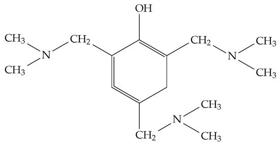
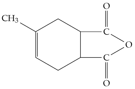
The binder matrix was based on epoxy resin CYD-128 (Hefei TNJ Chemical Industry Co., Ltd., Hefei, China; Scheme 1) [36], cured with iso-methyltetrahydrophthalic anhydride (iso-MTHPA; Scheme 2) , in the presence of the accelerator 2,4,6-tris(dimethylaminomethyl)phenol UP-606/2 (Sterlitamak Petrochemical Plant JSC, Russia; Scheme 3). The epoxy resin CYD-128 was chosen as the matrix material because it is a domestic analog of ED-22, meeting all technical specifications including viscosity, curing time, and mechanical properties after curing. The choice of CYD-128 also ensures continuity with our previous studies on ED-20 and ED-22 resins. This resin possesses the necessary processing characteristics for use with basalt and glass fibers and exhibits high mechanical performance after curing. The detailed characteristics of the GFRP and BFRP plates are presented in our previous study [14].

Scheme 1.
The chemical structure of the diglycidyl ether of bisphenol A (CYD-128).
Scheme 2.
The chemical structure of the isomethyltetrahydrophthalic anhydride (iso MTHPA).
Scheme 3.
The chemical structure of the 2,4,6-tris(dimethylaminomethyl)phenol (DMP-30).
GFRP plates (14 layers) and BFRP plates (18 layers) were manufactured using the vacuum infusion method, followed by curing in molds at for 4 h. The fabricated plates had dimensions of . The fabricated samples are shown in Figure 1. The epoxy matrix content was 22.9 ± 0.04 wt% in GFRP and 28.1 ± 0.04 wt% in BFRP.
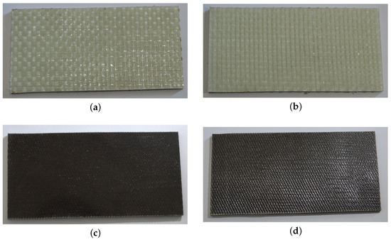
Figure 1.
Photographs of the fabricated samples: (a) a mold side of GFRP, (b) a bag side GFRP, (c) a mold side of BFRP, (d) a bag side BFRP.
2.2. Material Exposure
GFRP and BFRP plates were exposed with the mold side facing the sun for three years in Yakutsk on outdoor racks (54 cm above ground, inclination). Properties were evaluated in the as-received (initial) state and after 1, 2, and 3 years of exposure, corresponding to the initial phase of long-term degradation studies. Further investigations are planned for 5- and 10-year exposure periods to evaluate later stages of material aging.
2.3. Mass Change Measurement
Two additional specimen sets (10 × 10, 20 × 20, 40 × 40 mm; four replicates per size) were dried, measured, and weighed prior to exposure. One set was placed outdoors (19 April 2024–30 May 2025; 405 days), the other in an unheated indoor shed simulating ambient temperature without solar UV. Thickness and mass were recorded 193 times (∼every 2 days) using a micrometer (±0.01 mm) and electronic balance (±0.0001 g).
2.4. Matrix Content
Epoxy content was determined by calcining specimens at 600 °C for 6 h in porcelain crucibles, followed by weighing on an analytical balance (±0.0001 g). Mass fraction was calculated from the difference between initial and post-calcination mass.
2.5. SEM and Surface Roughness
Surface degradation and microstructural changes were examined using a scanning electron microscope (SEM, JSM-7800F, JEOL, Tokyo, Japan) operated at low accelerating voltage under high-vacuum conditions. The arithmetic average surface roughness (, µm) was determined using a portable profilometer Surftest SJ-201P (Mitutoyo, Kawasaki-shi, Japan). Following GOST 2789-73 [37], surface roughness was evaluated using the arithmetic mean deviation of the profile (Ra), which is considered the most representative parameter. The parameter was calculated as the arithmetic mean of the absolute deviations of the surface profile () from the mean line over the evaluation length (l):
2.6. Tensile Testing
Tensile strength () and modulus () were determined per ASTM D3039/ D3039M-17 [38] using five specimens per composite type (10 × 250 ± 2 mm) with 10 × 75 ± 2 mm tabs inclined at . Gauge length was ≥95 ± 2 mm, test speed 2 mm/min, extensometer gauge length 50 mm. Specimens were dried at 60 °C for 72 h prior to testing.
2.7. Dynamic Mechanical Analysis (DMA)
DMA was performed per ISO 6721 [39] using a DMA 242C (Netzsch, Selb, Germany) in three-point bending (span 40 mm), 25–150 °C, 5 °C/min, 10 µm amplitude, 1 Hz, under argon. Glass transition temperature () and transition limits (, ) were determined from inflection points or maxima. Face and back sides were analyzed separately.
2.8. Thermomechanical Analysis (TMA)
CLTE was measured per ISO 11359-2 [40] on a TMA 202 C (Netzsch) at 5 °C/min in helium (70 ml/min), 3 cN load [18]. Thickness change , relative change , and CLTE
were determined perpendicular to the reinforcement plane from to 100 °C, where H is thickness at temperature T and is initial thickness.
3. Results and Discussion
3.1. Climate Conditions of Exposure
Figure 2 shows the average monthly climatic parameters of Yakutsk over the three-year exposure period of glass fiber reinforced polymer (GFRP) and basalt fiber reinforced polymer (BFRP) samples (2022–2024).
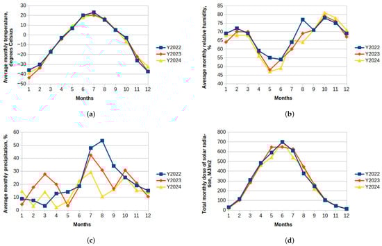
Figure 2.
Average monthly climatic parameters in Yakutsk for the three-year exposure period of GFRP and BFRP samples: (a) air temperature, (b) relative humidity, (c) total solar radiation dose, (d) precipitation.
The climate of Yakutsk is characterized by a sharply continental type with low precipitation (about 230 mm/year) and an average relative humidity of approximately 68%. The main feature is the large temperature amplitude, with a difference between winter and summer temperatures reaching about 90 °C. The winter period lasts from October to April, while spring and autumn are very short. Internal stresses in polymer composites increase notably during these transition seasons and depend on the relationship Equation (1).
Despite the reduced sunlight duration in winter, the annual total solar radiation dose was approximately 3600 MJ/m2, consistent with previously reported data [41] (3516 MJ/m2). Table 2 presents the cumulative number of temperature transitions for GFRP and BFRP during the 2023 and 2024 years, corresponding to extremely cold environmental conditions.
Table 2.
Number of transitions through temperature points in GFRP and BFRP during the 2023–2024.
3.2. Changes in Mechanical Properties After Exposure
Table 3 summarizes the tensile strength and tensile modulus of GFRP and BFRP samples before and after 1, 2, and 3 years of outdoor exposure in Yakutsk. Mechanical properties of the composites was measured for five specimens of each type. Results are presented as mean ± standard deviation (SD, n = 5).
Table 3.
Mechanical properties of GFRP and BFRP before and after exposure.
After 1 year of exposure, the tensile strength of GFRP decreased by 11%, and the modulus decreased by 21%. These reductions continued over subsequent years, reaching 24–32%. BFRP showed similar trends but with less degradation (6–12% after 3 years). These results align with previous studies [12,14,18] that report higher durability of BFRP compared to GFRP under aggressive environmental conditions.
3.3. Changes in Binder Mass Fraction and Surface Morphology After Exposure
Table 4 presents the binder (epoxy matrix) mass fraction determined by ashing method before and after exposure in extreme cold climate. Mass fraction of the binder in the composite (wt%) was measured for 3 specimens of each type. Results are presented as mean ± standard deviation (SD, n = 3).
Table 4.
Binder mass fraction (wt%) in GFRP and BFRP before and after exposure.
Table 5 presents the relative binder mass fraction (wt%) defined as the ratio of the binder mass fraction after exposure to its initial value.
Table 5.
Relative binder mass fraction (wt%) in GFRP and BFRP after exposure.
Reduction in binder content is related to the mechanochemical degradation of the matrix due to internal stresses [22,23,24]. A comparison of GFRP and BFRP shows that the degradation rate differs significantly. For GFRP, the binder content decreases steadily from 24.8% to 19.4% over three years, corresponding to a loss of almost 27% of the initial binder (Table 5). In contrast, BFRP demonstrates only a slight reduction almost 8% of the initial binder.
The effects of environmental exposure on the surface morphology of glass- and basalt-fiber reinforced polymer composites were investigated using scanning electron microscopy (SEM). Figure 3 and Figure 4 present representative SEM images of GFRP and BFRP surfaces, respectively, highlighting differences between sun-facing and shaded sides before and after three years of outdoor exposure. Binder degradation and subsequent fiber debonding were observed, particularly on surfaces exposed to solar radiation.
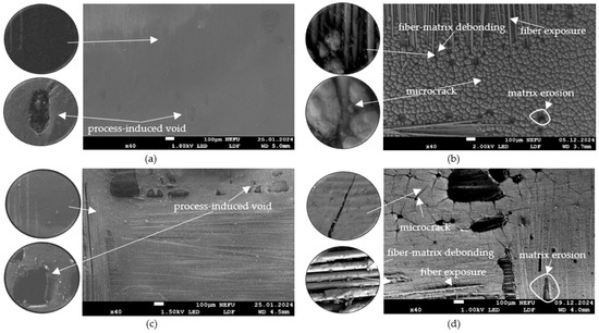
Figure 3.
Surface morphology of GFRP under SEM: sun-facing surface (a) before exposure, (b) after 3 years; shaded surface (c) before exposure, (d) after 3 years.
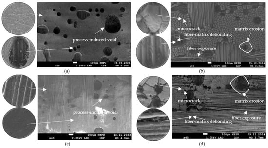
Figure 4.
Surface morphology of BFRP under SEM: sun-facing surface (a) before exposure, (b) after 3 years; shaded surface (c) before exposure, (d) after 3 years.
The extent of surface damage is evidenced by the increase in the arithmetic mean roughness parameter () after open-stand exposure. Each reported value represents the mean of at least 60 measurements obtained at different surface locations to ensure reproducibility. As shown in Table 6 and Figure 5, indicating that both composites undergo surface degradation manifested as microcracking, resin erosion.
Table 6.
Surface average roughness parameter Equation (2) of GFRP, BFRP in the initial state and after 2 and 3 years of open-stand exposure in Yakutsk.
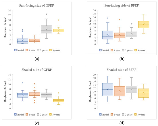
Figure 5.
Variation in surface roughness Equation (2) over the years represented as box-plots: sun-facing surface of (a) GFRP, (b) BFRP; shaded surface of (c) GFRP, (d) BFRP.
3.4. Mass Loss Kinetics: Model and Experiment
Prolonged exposure to climatic factors leads to changes in the mass of polymer composite materials (PCMs) such as GFRP and BFRP. Existing data [22,23,24] indicate that mass loss is associated with mechanical degradation of the polymer matrix caused by internal stresses arising from the mismatch in the coefficients of linear thermal expansion (CLTE) between the matrix and the reinforcing fibers. Additionally, UV radiation exacerbates the degradation processes. On the other hand, a seasonal mass increase with an annual periodicity, attributed to moisture sorption, has been reported in [25,26,28] for various polymer composite materials exposed to open-air climatic conditions.
3.4.1. Model
The mass change of polymer composite materials exposed to extreme cold conditions is modeled as a superposition of two competing processes: moisture sorption, which increases the mass, and matrix degradation, which decreases the mass. The relative mass change at time t, denoted as , can be expressed as
where represents the mass change due to moisture sorption, and corresponds to the mass loss due to degradation caused by solar ultraviolet (UV) radiation and internal thermal stresses.
The relative mass change is defined as
where is the initial dry mass of the specimen, and is the mass of the specimen after exposure for a duration t.
The sorption term is described by a periodic function accounting for seasonal fluctuations in moisture content [28]:
where is the average moisture content over the exposure period (%), is the amplitude of seasonal moisture fluctuations (%), days is the period of seasonal variation, and is the phase shift (in radians).
It is assumed that low-molecular weight degradation products of the epoxy binder at the micro scale “randomly jump” through the free volume of the binder and migrate into the external environment. Furthermore, surface matrix erosion is assumed to exhibit a stochastic character. So the degradation-induced mass loss kinetics is modeled by the one-dimensional solution to Fick’s diffusion second law with constant parameters [42,43], given by
where an one-dimensional sample size is introduced, reflecting the dependence on the sample geometry
is the limiting mass loss due to complete degradation (%), D is the diffusion coefficient of degradation products (mm2/day), and L, W, and H denote the specimen’s length, width, and thickness (mm), respectively.
3.4.2. Experiment
A typical example of the kinetics of mass change for specimens of different sizes (10 × 10, 20 × 20, and 40 × 40 mm) over 405 days of exposure in an open stand and in a hangar are shown in Figure 6 and Figure 7. A general trend is observed—mass loss increases with exposure time (in agreement with [25,26,27,28]).
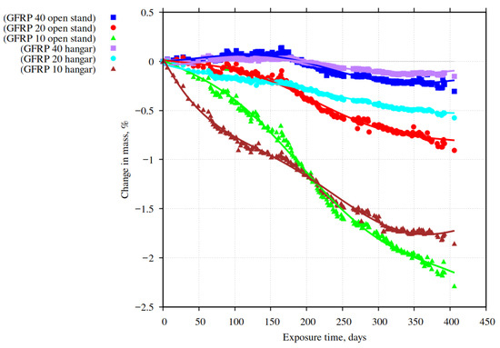
Figure 6.
Mass change kinetics of GFRP samples during outdoor and hangar exposure.
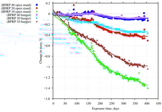
Figure 7.
Mass change kinetics of BFRP samples during outdoor and hangar exposure.
The Figure 8 shows the relative mass changes after 405 days of exposure in an open site and in a hangar for GFRP and BFRP specimens with sizes of 10 × 10, 20 × 20, and 40 × 40 mm (four specimens for each size), presented as box plots.
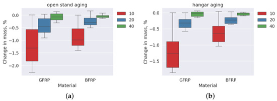
Figure 8.
Effect of exposure conditions and sample size on mass changes represented as box-plots: (a) outdoor exposure, (b) hangar exposure.
Mass loss was highest in 10 × 10 mm samples during outdoor exposure (mean values: 2.3% for GFRP, 1.3% for BFRP) and decreased with sample size. In the hangar, where UV radiation was absent, mass loss decreased by 30–50%, indicating a significant role of internal thermal stresses in degradation. Seasonal mass gain (0.1–0.15%) in larger samples is attributed to moisture sorption, in agreement with previous works [25,26,28]. BFRP exhibits higher resistance to degradation than GFRP under both open-stand and hangar exposure conditions.
3.4.3. Model Parameters
The parameters of the model (Equation (4)) for GFRP and BFRP, obtained by fitting the experimental data using Python 3.12.3, and averaged over four replicates for each specimen size, are presented in Table 7 and Table 8. The coefficients of determination are close to unity in all cases, indicating the high adequacy of the proposed model ( would mean that all observed data perfectly match the model predictions).
Table 7.
Model parameters (Equation (4)) for GFRP.
Table 8.
Model parameters (Equation (4)) for BFRP.
The removal of degradation products from the bulk of GFRP and BFRP specimens during exposure on the open stand and in the hangar follows the law of Fickian desorption of low-molecular-weight products. This is supported by the pronounced dependence of the diffusion coefficient on the specimen dimensions, ranging from mm2/day to 0.29 mm2/day.
The removal of degradation products from the specimen bulk is accompanied by moisture uptake, which varies with the season of exposure. The average moisture content over the exposure period ranges from 0.01% to 0.19%, depending on the material composition, specimen size, and exposure conditions.
The proposed diffusion-based degradation model Equation (4) was quantitatively validated due to the significant mass changes observed in small-size specimens. In typical exposure studies of polymer composite materials, considerably larger plates are employed [18,19,20,22,24,25]. The weighing sensitivity for such macro-specimens is insufficient to reliably detect their minor mass losses.
3.5. Dynamic Mechanical Analysis of GFRP and BFRP
Dynamic mechanical analysis (DMA) has been widely applied to identify dominant physicochemical transformations in polymer matrices of composite materials [18,32,41,44]. In the present study, DMA was employed to assess changes in the thermomechanical properties of GFRP and BFRP after long-term climatic aging.
Figure 9 and Figure 10 present a typical example of the temperature dependences of the storage modulus and the loss modulus for specimens cut from the sun-facing surfaces of GFRP and BFRP laminated plates in the as-received condition and after three years of open-stand exposure in Yakutsk. Table 9 and Table 10 presents the quantitative DMA results, for specimens cut from the sun-facing and shaded surfaces of GFRP and BFRP laminated plates in the as-received condition and after three years of open-stand exposure in Yakutsk.
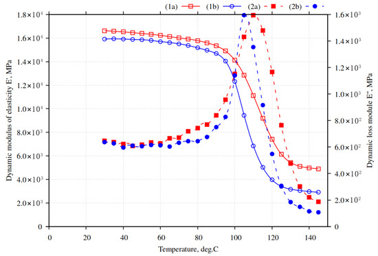
Figure 9.
Temperature dependences of the storage modulus (1) and the loss modulus (2) for the sun-facing side of GFRP in the initial state (a) and after 3 years of open-stand exposure in Yakutsk (b).
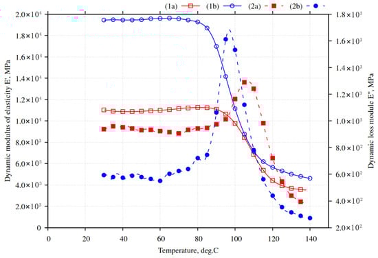
Figure 10.
Temperature dependences of the storage modulus (1) and the loss modulus (2) for the sun-facing side of BFRP in the initial state (a) and after 3 years of open-stand exposure in Yakutsk (b).
Table 9.
DMA characteristics of GFRP in the initial state and after 2 and 3 years of open-stand exposure in Yakutsk.
Table 10.
DMA characteristics of BFRP in the initial state and after 2 and 3 years of open-stand exposure in Yakutsk.
For GFRP in the initial state, the onset and completion temperatures of the glass-to-rubber transition of the epoxy matrix were °C and °C, respectively, while the glass transition temperature determined from the peak was °C. After three years of environmental exposure, these temperatures decreased by 11–14 °C (Table 9), indicating epoxy matrix degradation due to solar UV radiation and internal thermal stresses. The ratio decreased from to (a 40% reduction), consistent with the kinetic theory of high elasticity [45], reflecting reduced crosslink density and enhanced segmental mobility of macromolecular chains.
For BFRP, the initial characteristic temperatures , , and were °C, °C, and °C, respectively. After three years of aging, these parameters decreased by only 4–6 °C (Table 10), and dropped by 29%. These findings indicate less pronounced epoxy matrix degradation in BFRP compared to GFRP.
The comparative analysis (Table 11) demonstrates that the decrease in the glass transition temperatures (, , and ) and in the modulus ratio is significantly smaller in BFRP than in GFRP after the same period of climatic aging. This indicates a higher resistance of the basalt–fiber-reinforced epoxy matrix to UV-induced and thermally induced degradation processes.
Table 11.
Relative changes in DMA parameters of GFRP and BFRP after 3 years of open-stand exposure in Yakutsk.
3.6. Thermomechanical Analysis of GFRP and BFRP Under Climatic Exposure
The thermomechanical analysis (TMA) conducted in this study provided additional insight into the aging mechanisms of GFRP and BFRP (Figure 11 and Figure 12, Table 12).
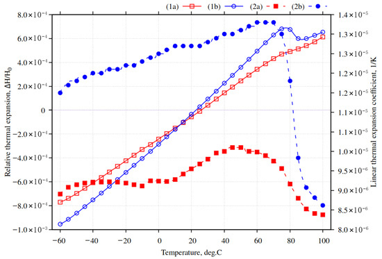
Figure 11.
A typical example of the temperature dependences of the relative thermal expansion (1) and the coefficient of linear thermal expansion (2) of GFRP in its initial state (a) and after 3 years of exposure at an outdoor stand in Yakutsk (b).
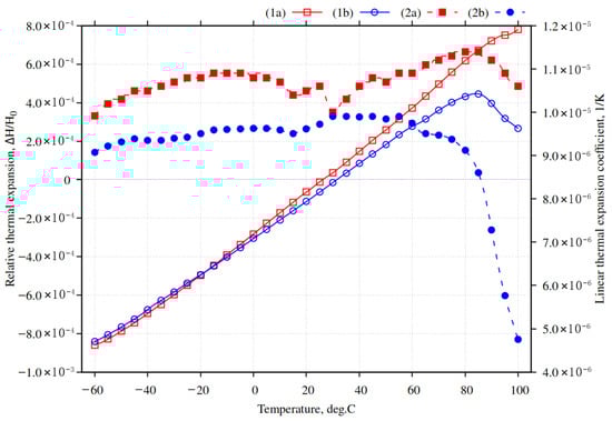
Figure 12.
A typical example of the temperature dependences of the relative thermal expansion (1) and the coefficient of linear thermal expansion (2) of BFRP in its initial state (a) and after 3 years of exposure at an outdoor stand in Yakutsk (b).
Table 12.
Coefficients of linear thermal expansion of GFRP and BFRP in the initial state and after 2 and 3 years of exposure at an outdoor stand in Yakutsk ( 1/°C).
As shown in Figure 11, the relative thermal expansion of GFRP increases quasi-linearly over the temperature range from °C to °C in both the initial state and after 3 years of exposure to the climate of Yakutsk. In the entire glassy state of the epoxy matrix, the coefficient of linear thermal expansion of GFRP increased by 20–30% after exposure. This increase can be explained by structural changes in the polymer matrix: prolonged exposure to solar UV radiation and thermal cycling induces partial degradation of the epoxy network, breaking some covalent and hydrogen bonds, and causes microcracking and loosening of the matrix. As a result, the intermolecular interactions that normally constrain the thermal motion of polymer chains are weakened, leading to higher segmental mobility. Additionally, internal thermal stresses accumulated during repeated heating and cooling cycles further disrupt the matrix–fiber interface, reducing the constraining effect of the glass fibers on the matrix. Together, these mechanisms result in an overall increase in the linear thermal expansion coefficient of the composite.
BFRP proved to be a more stable material. As shown in Figure 12 and Table 12, the coefficient of linear thermal expansion in the glassy state of BFRP decreased by 5–10% after 3 years of exposure. This slight reduction can be attributed to the higher thermal stability and lower intrinsic thermal expansion of basalt fibers, which more effectively constrain the matrix compared to glass fibers. Additionally, partial post-curing and relaxation of the epoxy matrix during long-term UV and thermal exposure can lead to local densification of the polymer network, reducing segmental mobility. The combination of a stiffer fiber–matrix interface and a denser matrix results in a minor overall decrease in the linear thermal expansion of the composite.
Overall, the analysis of the experimental results obtained by DMA and TMA confirms the occurrence of epoxy matrix degradation in the studied composites and demonstrates the superior climatic resistance of BFRP compared to GFRP.
4. Conclusions
Exposure of GFRP and BFRP laminates for three years under the Arctic climate of Yakutsk resulted in degradation of the epoxy matrix. This was confirmed by reductions in tensile strength and elastic modulus, decreased polymer content, lowered glass transition temperature, and altered coefficients of linear thermal expansion over a wide temperature range.
In studies of the environmental durability of polymer binders and other polymer composite materials, it is crucial not only to assess conventional mechanical properties but also to carefully monitor changes in the mass of the tested samples, identifying increases due to moisture sorption and decreases due to material degradation. Such measurements provide valuable insights into the predominance of moisture uptake versus structural deterioration.
Comparison of experimental results and mathematical modeling demonstrated that the primary cause of polymer matrix degradation is the action of abrupt internal stresses arising during thermal cycling under extreme cold climate conditions, due to differences in the coefficients of linear thermal expansion of glass and basalt fibers and the epoxy matrix. The proposed diffusion-based degradation model was validated by significant mass changes in small-sized samples during both outdoor and controlled hangar exposure.
Comparative analysis of mechanical properties, mass loss, dynamic mechanical and thermomechanical behavior, and matrix content consistently demonstrated the superior climatic durability of BFRP relative to GFRP. The practical implications of these findings support the informed selection and application of polymer composites, particularly BFRP, in construction materials for cold-region infrastructures.
Author Contributions
Conceptualization, O.V.S., A.K.K. and M.P.L.; methodology, O.V.S.; formal analysis, A.S.K., A.A.K. and A.A.G.; investigation, A.S.K., A.A.K. and A.K.K.; writing—original draft preparation, O.V.S. and A.K.K.; writing—review and editing, A.A.G. and A.K.K.; funding acquisition, A.K.K. and M.P.L. All authors have read and agreed to the published version of the manuscript.
Funding
This research was funded by the Russian Science Foundation (RSF) under grant No. 25-69-00009. For more information, please visit the project page: https://rscf.ru/project/25-69-00009/, accessed on 7 September 2025.
Institutional Review Board Statement
Not applicable.
Data Availability Statement
The original contributions presented in this study are included in the article. Further inquiries can be directed to the corresponding authors.
Acknowledgments
This research was carried out using scientific equipment of the shared core facilities of the Federal Research Center ‘YSC SB RAS’.
Conflicts of Interest
The authors declare no conflicts of interest. The funders had no role in the design of the study; in the collection, analyses, or interpretation of data; in the writing of the manuscript; or in the decision to publish the results.
Abbreviations
The following abbreviations are used in this manuscript:
| ASTM | American Society for Testing and Materials |
| BFRP | Basalt Fiber Reinforced Polymer |
| CLTE | Coefficients of Linear Thermal Expansion |
| DMA | Dynamic Mechanical Analysis |
| GFRP | Glass Fiber Reinforced Polymer |
| ISO | International Organization for Standardization |
| Tg | Glass Transition Temperature |
| TMA | Thermomechanical Analysis |
| UV | Ultraviolet |
References
- Jagadeesh, P.; Rangappa, S.M.; Siengchin, S. Basalt fibers: An environmentally acceptable and sustainable green material for polymer composites. Constr. Build. Mater. 2024, 436, 136834. [Google Scholar] [CrossRef]
- Elmahdy, A.; Verleysen, P. Comparison between the mechanical behavior of woven basalt and glass epoxy composites at high strain rates. Mater. Today Proc. 2021, 34, 171–175. [Google Scholar] [CrossRef]
- Duan, S.-J.; Feng, R.-M.; Yuan, X.-Y.; Song, L.-T.; Tong, G.-S.; Tong, J.-Z. A Review on research advances and applications of basalt fiber-reinforced polymer in the construction industry. Buildings 2025, 15, 181. [Google Scholar] [CrossRef]
- Tavadi, A.R.; Naik, Y.; Kumaresan, K.; Jamadar, N.I.; Rajaravi, C. Basalt fiber and its composite manufacturing and applications: An overview. Int. J. Eng. Sci. Technol. 2021, 13, 50–56. [Google Scholar] [CrossRef]
- Yan, W.; Shi, J.; Cao, X.; Zhang, M.; Li, L.; Jiang, J. A Review on the applications of basalt fibers and their composites in infrastructures. Buildings 2025, 15, 2525. [Google Scholar] [CrossRef]
- Liu, Y.; Zhang, M.; Liu, H.; Tian, L.; Liu, J.; Fu, C.; Fu, X. Properties of basalt fiber core rods and their application in composite cross arms of a power distribution network. Polymers 2022, 14, 2443. [Google Scholar] [CrossRef]
- Monaldo, E.; Nerilli, F.; Vairo, G. Basalt-based fiber-reinforced materials and structural applications in civil engineering. Compos. Struct. 2019, 214, 246–263. [Google Scholar] [CrossRef]
- Wang, Z.K.; Zhao, X.L.; Xian, G.J.; Wu, G.; Raman, R.K.S.; Al-Saadi, S. Long-term durability of basalt- and glass-fibre reinforced polymer (BFRP/GFRP) bars in seawater and sea sand concrete environment. Constr. Build. Mater. 2017, 139, 467–489. [Google Scholar] [CrossRef]
- Wang, Z.; Zhao, X.-L.; Xian, G.; Wu, G.; Raman, R.K.S.; Al-Saadi, S. Durability study on interlaminar shear behaviour of basalt-, glass- and carbon-fibre reinforced polymer (B/G/CFRP) bars in seawater sea sand concrete environment. Constr. Build. Mater. 2017, 156, 985–1004. [Google Scholar] [CrossRef]
- Wang, M.; Zhang, Z.; Yubin, L.; Min, L.; Zhijie, S. Chemical durability and mechanical properties of alkali-proof basalt fiber and its reinforced epoxy composites. J. Reinf. Plast. Compos. 2008, 27, 393–407. [Google Scholar] [CrossRef]
- Wu, G.; Wang, X.; Wu, Z.; Dong, Z.; Zhang, G. Durability of basalt fibers and composites in corrosive environments. J. Compos. Mater. 2015, 49, 873–887. [Google Scholar] [CrossRef]
- Hashim, U.R.; Jumahat, A.; Jawaid, M.; Dungani, R.; Alamery, S. Effects of accelerated weathering on degradation behavior of basalt fiber reinforced polymer nanocomposites. Polymers 2020, 12, 2621. [Google Scholar] [CrossRef]
- Zhao, J.; Cai, G.; Cui, L.; Larbi, A.S.; Tsavdaridis, K.D. Deterioration of basic properties of the materials in FRP-strengthening RC structures under ultraviolet exposure. Polymers 2017, 9, 402. [Google Scholar] [CrossRef]
- Lukachevskaia, I.G.; Kychkin, A.; Kychkin, A.K.; Vasileva, E.D.; Markov, A.E. Effect of 2000-hour ultraviolet irradiation on surface degradation of glass and basalt fiber reinforced laminates. Polymers 2025, 17, 1980. [Google Scholar] [CrossRef] [PubMed]
- Dorigato, A.; Pegoretti, A. Fatigue resistance of basalt fibers-reinforced laminates. J. Compos. Mater. 2012, 46, 1773–1785. [Google Scholar] [CrossRef]
- Mahesha, C.R.; Shivarudraiah, N.M.; Suprabha, R. Solid particle erosion of basalt fiber and glass fiber-epoxy composite. Int. J. Mech. Prod. Eng. 2014, 2, 30–34. [Google Scholar] [CrossRef]
- Shishevan, F.A.; Akbulut, H.; Bonab, M.A.M. Low Velocity Impact Behavior of Basalt Fiber-Reinforced Polymer Composites. J. Mater. Eng. Perform. 2017, 26, 2890–2900. [Google Scholar] [CrossRef]
- Startsev, O.V.; Lebedev, M.P.; Kychkin, A.K. Aging of basalt plastics in open climatic conditions. Polym. Sci. Ser. D 2022, 15, 101–109. [Google Scholar] [CrossRef]
- Dexter, H.B. Long-Term Environmental Effects and Flight Service Evaluation of Composite Materials. 1987. Available online: https://ntrs.nasa.gov/citations/19870008425 (accessed on 28 July 2025).
- Baker, D.J. Ten-Year Ground Exposure of Composite Materials Used on the Bell Model 206L Helicopter Flight Service Program. 1994. Available online: https://ntrs.nasa.gov/citations/19950005944 (accessed on 29 July 2025).
- Hahn, H.T. Residual stresses in polymer matrix composite laminates. J. Compos. Mater. 1976, 10, 266–278. [Google Scholar] [CrossRef]
- Dutta, P.K. Structural fiber composite materials for cold regions. J. Cold Reg. Eng. 1988, 2, 124–134. [Google Scholar] [CrossRef]
- Kablov, E.N.; Startsev, V.O. The influence of internal stresses on the aging of polymer composite materials: A review. Mech. Compos. Mater. 2021, 57, 565–576. [Google Scholar] [CrossRef]
- Startsev, O.V.; Lebedev, M.P.; Kychkin, A.K. Aging of polymer composites in extremely cold climates. Izv. Altai State Univ. 2020, 1, 41–51. [Google Scholar] [CrossRef]
- Pride, R.A. Environment Effects of Composites for Aircraft. CTOL Transport Technol. 239–258. 1978. Available online: https://ntrs.nasa.gov/api/citations/19780019118 (accessed on 28 July 2025).
- Startsev, V.O.; Startsev, O.V.; Zeleneva, T.O.; Vardanyan, A.M. Influence of precipitation on changes in the mass of samples of polymeric composite materials in open climatic conditions. Aviat. Mater. Technol. 2024, 1, 136–154. (In Russian) [Google Scholar] [CrossRef]
- Vodicka, R.; Nelson, B.; Berg, J.V.; Chester, R. Long-Term Environmental Durability of F/A-18 Composite Material; DSTO-TN-0826; DSTO Aeronautical and Maritime Research Lab: Melbourn, Australia, 1999. [Google Scholar]
- Salnikov, V.G.; Startsev, O.V.; Lebedev, M.P.; Kopyrin, M.M.; Vapirov, Y.M. The influence of diurnal and seasonal variations of relative humidity and temperature on coal–plastic moisture saturation in open climatic conditions. Polym. Sci. Ser. D 2023, 16, 131–136. [Google Scholar] [CrossRef]
- Menard, K. Dynamic Mechanical Analysis: A Practical Introduction, 2nd ed.; CRC Press: Boca Raton, FL, USA, 2008. [Google Scholar] [CrossRef]
- Sowjanya, Y.; Jayaprasad, V.; Kumar, K.D.; Mohanrao, N. Review on thermomechanical analysis of nano composites. J. Mech. Civ. Eng. 2016, 13, 95–100. [Google Scholar] [CrossRef]
- Kulawik, J.; Szeglowski, Z.; Czapla, T.; Kulawik, J.P. Determination of glass-transition temperature, thermal expansion and, shrinkage of epoxy resins. Colloid Polym. Sci. 1989, 267, 970–975. [Google Scholar] [CrossRef]
- Gavrilieva, A.A.; Startsev, O.V.; Lebedev, M.P.; Krotov, A.S.; Kychkin, A.K.; Lukachevskaya, I.G. Size effects in climatic aging of epoxy basalt fiber reinforcement bar. Polymers 2024, 16, 2550. [Google Scholar] [CrossRef]
- Lu, Z.Y.; Xian, G.J.; Li, H. Experimental study on the mechanical properties of basalt fibres and pultruded BFRP plates at elevated temperatures. Polym. Polym. Compos. 2015, 23, 277–284. [Google Scholar] [CrossRef]
- Lu, Z.; Xian, G.; Rashid, K. Creep behavior of resin matrix and basalt fiber reinforced polymer (BFRP) plate at elevated temperatures. J. Compos. Sci. 2017, 1, 3. [Google Scholar] [CrossRef]
- Kychkin, A.K.; Gavrilieva, A.A.; Kychkin, A.A.; Lukachevskaya, I.G.; Lebedev, M.P. The Initial Stage of Climatic Aging of Basalt-Reinforced and Glass-Reinforced Plastics in Extremely Cold Climates: Regularities. Polymers 2024, 16, 866. [Google Scholar] [CrossRef] [PubMed]
- Yang, G.; Fu, S.-Y.; Yang, F.-P. Preparation and mechanical properties of modified epoxy resins with flexible diamines. Polymer 2007, 48, 302–310. [Google Scholar] [CrossRef]
- GOST 2789–73; Surface Roughness. Parameters and Characteristics. Standards Publishing: Moscow, Russia, 1973.
- ASTM D3039/D3039M-17; Standard Test Method for Tensile Properties of Polymer Matrix Composite Materials. ASTM International: West Conshohocken, PA, USA, 2017.
- ISO 6721-11; Plasics—Determination of Dynamic Mechanical Properties—Part 11: Glass Transition Temperature. ISO: Geneva, Switzerland, 2012.
- ISO 11359-2; Plastics—Thermomechanical Analysis (TMA)—Part 2. Determination of Coefficient of Linear Thermal Expansion and Glass Transition Temperature. ISO: Geneva, Switzerland, 1999.
- Veligodskiy, I.M.; Koval, T.V.; Kurnosov, A.O.; Marakhovskiy, P.S. Study of resistance of glass fiber reinforced plastic to natural weathering in different climatic conditions. Tr. VIAM 2022, 11, 134–148. (In Russian) [Google Scholar] [CrossRef]
- Carslaw, H.S.; Jaeger, J.C. Conduction of Heat in Solids; Oxford Univ. Press: London, UK; New York, NY, USA, 1959. [Google Scholar] [CrossRef]
- Crank, J. The Mathematics of Diffusion, 2nd ed.; Clarendon Press: Oxford, UK, 1975. [Google Scholar]
- Koval’, T.V.; Veligodskii, I.M.; Gromova, A.A. Change in the properties of BSR-3m binder in vku-46 carbon-fiber-reinforced polymer after prolonged climatic aging. Polym. Sci. Ser. D 2023, 16, 687–693. [Google Scholar] [CrossRef]
- Mark, J.E. (Ed.) Physical Properties of Polymers Handbook, 2nd ed.; Springer: Berlin/Heidelberg, Germany, 2007. [Google Scholar]
Disclaimer/Publisher’s Note: The statements, opinions and data contained in all publications are solely those of the individual author(s) and contributor(s) and not of MDPI and/or the editor(s). MDPI and/or the editor(s) disclaim responsibility for any injury to people or property resulting from any ideas, methods, instructions or products referred to in the content. |
© 2025 by the authors. Licensee MDPI, Basel, Switzerland. This article is an open access article distributed under the terms and conditions of the Creative Commons Attribution (CC BY) license (https://creativecommons.org/licenses/by/4.0/).