


Flexural Testing of Steel-, GFRP-, BFRP-, and Hybrid Reinforced Beams

 ,
,
Abstract
1. Introduction
1.1. Research Significance
1.2. Research Objectives
- Compare the flexural strength of GFRP, BFRP, and hybrid reinforced beams to that of steel-reinforced beams;
- Analyze the deflection characteristics of each type of beam, focusing on the ductility behavior;
- Assess the cracking patterns and the overall failure modes to determine the suitability of GFRP, BFRP, and hybrid reinforcements for different structural applications;
- Examine whether hybrid reinforcement systems, such as Steel/GFRP, Steel/BFRP, and GFRP/BFRP combinations, offer better alternatives to traditional steel reinforcement, particularly in terms of ductility.
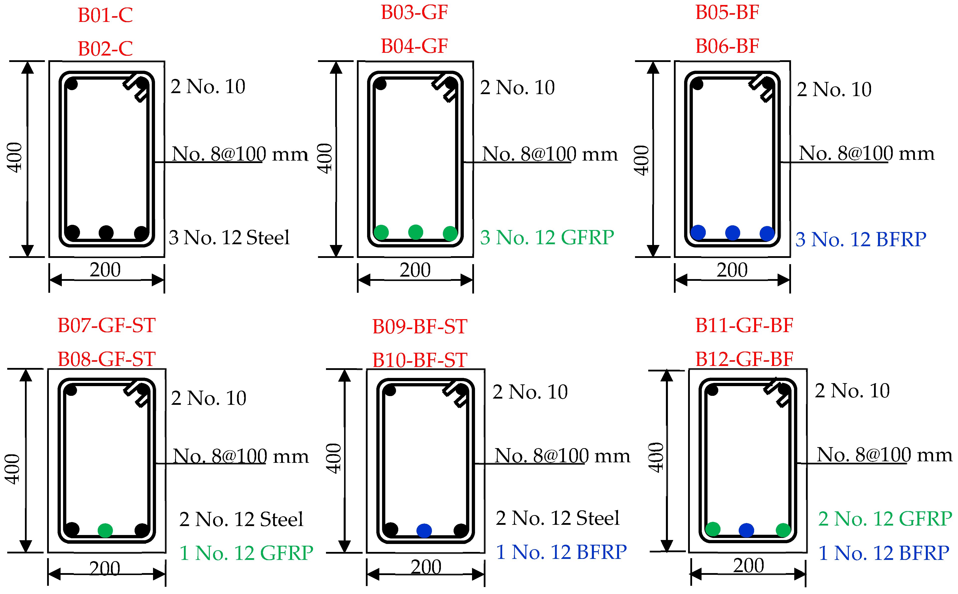
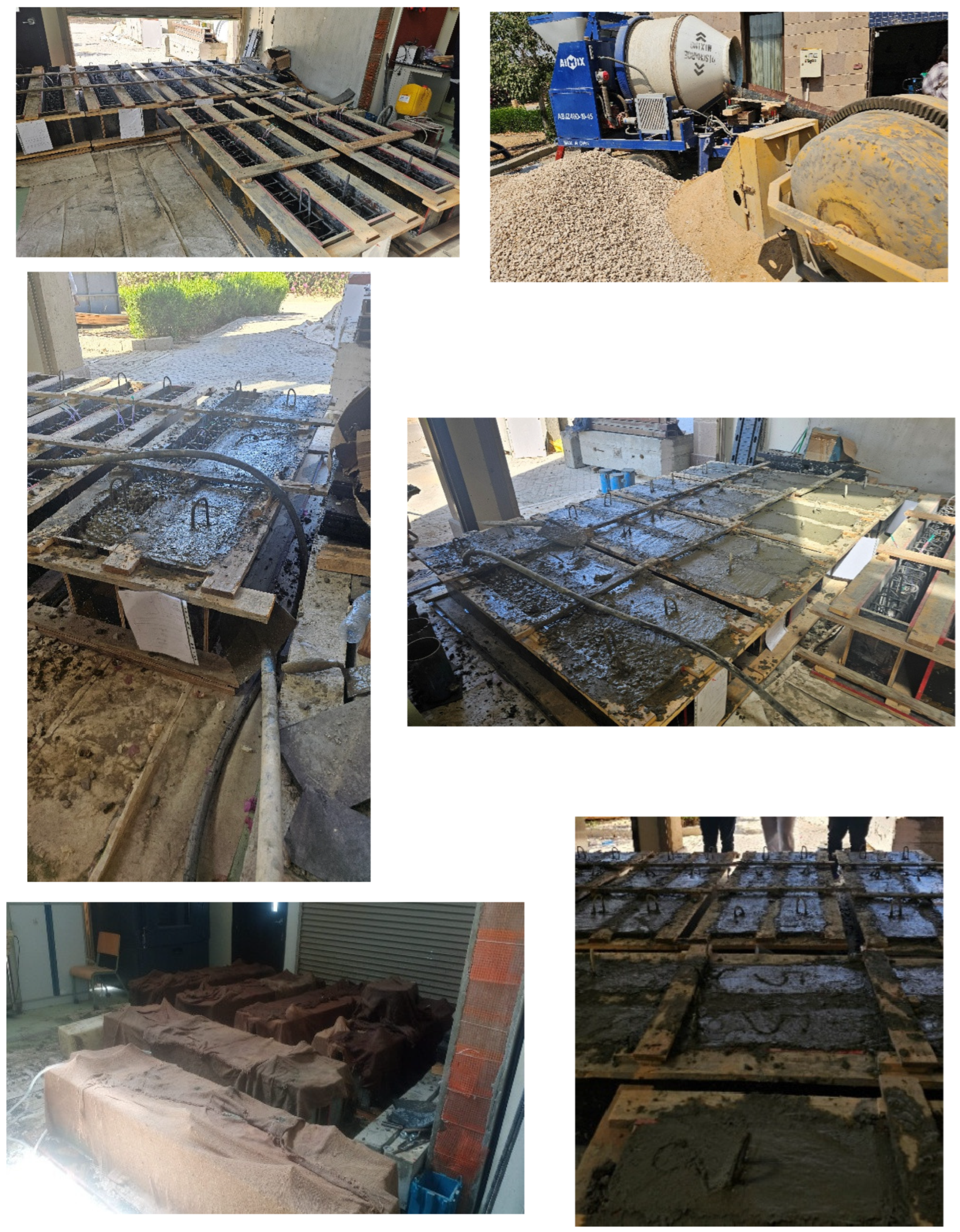
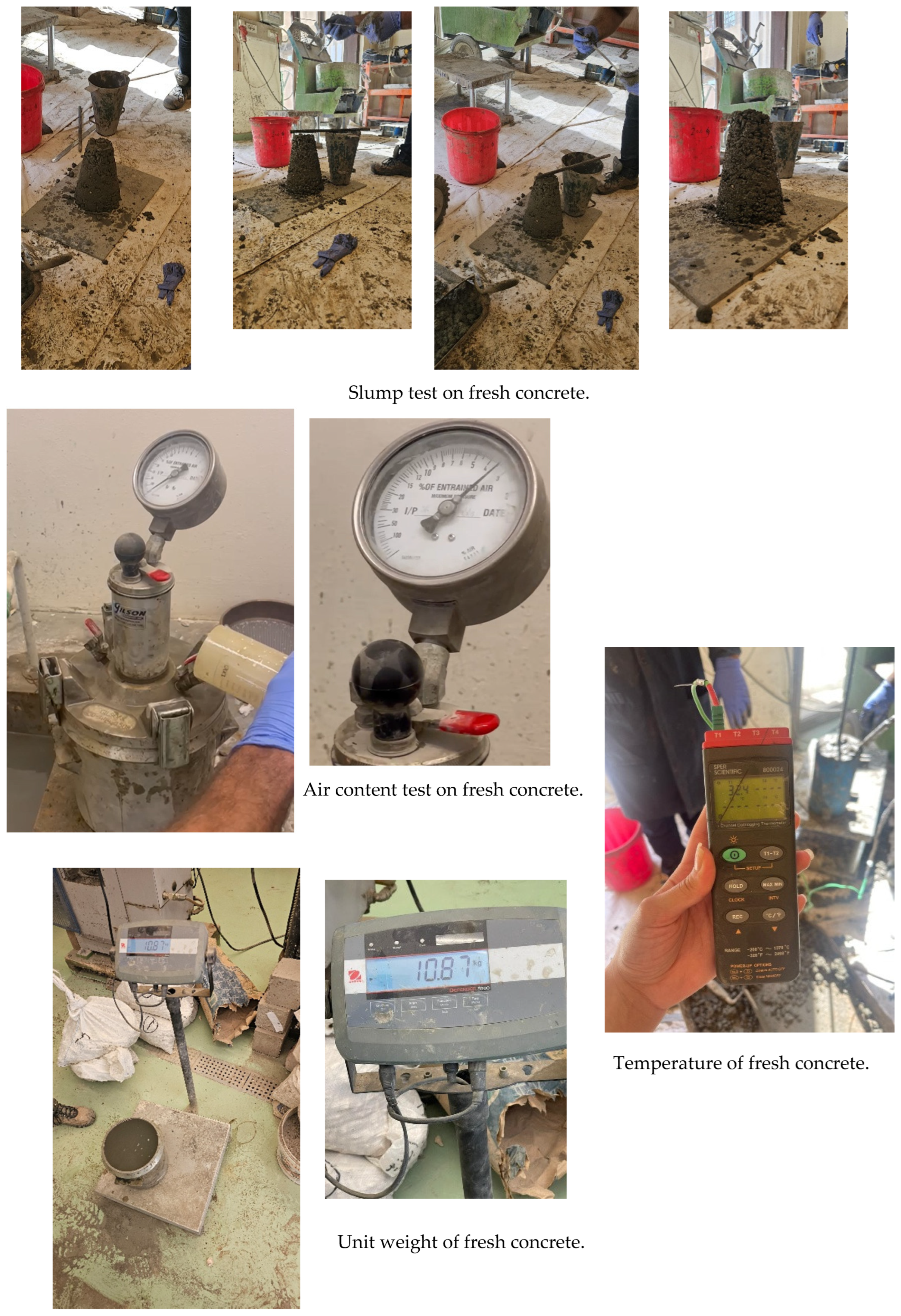
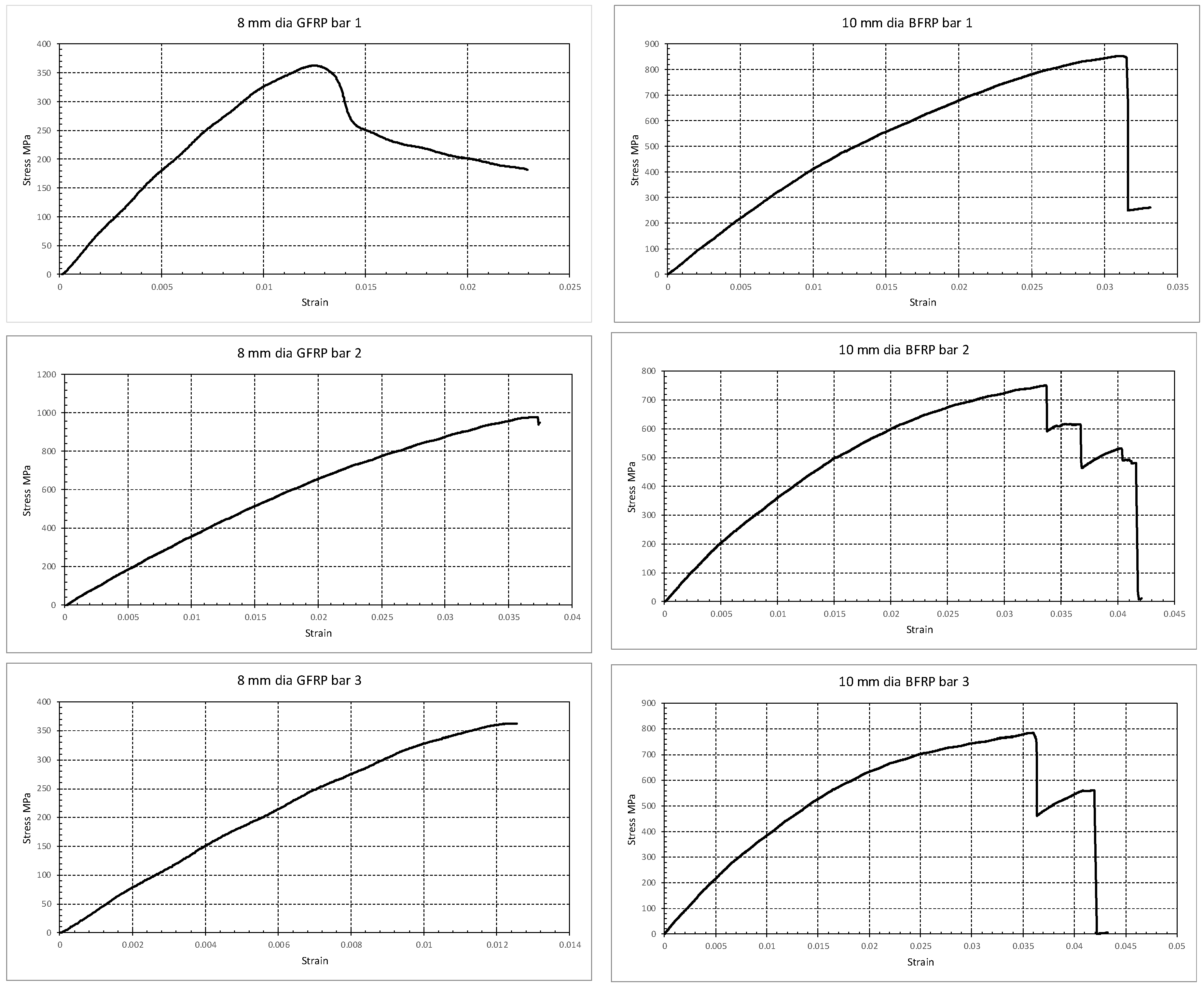
2. The Experimental Investigation: Materials and Methodology
- Beams reinforced with steel (control group);
- Beams reinforced with GFRP;
- Beams reinforced with BFRP;
- Beams reinforced with a hybrid of steel and GFRP;
- Beams reinforced with a hybrid of steel and BFRP;
- Beams reinforced with a hybrid of GFRP and BFRP.
- The flexural strength based on the nominal moment and load capacity;
- The deflection profiles to assess ductility;
- The crack propagation and failure modes of each reinforcement type;
- The ductility of beams compared to that of steel-reinforced beams.
- A total of 350 kg/m3 Ordinary Portland Cement;
- A w/c ratio of about 0.4;
- A total of 615 kg/m3 fine aggregates (sand);
- A total of 1100 kg/m3 coarse aggregate (1″, 2‴ equal portions);
- Super plasticizer Skiament C494 Type F.
3. The Analytical Investigation
3.1. Nominal Moment
3.2. Nominal Shear
3.3. Cracking Moment
3.4. Results of the Analytical Investigation
4. Experimental Investigation Results and Discussion
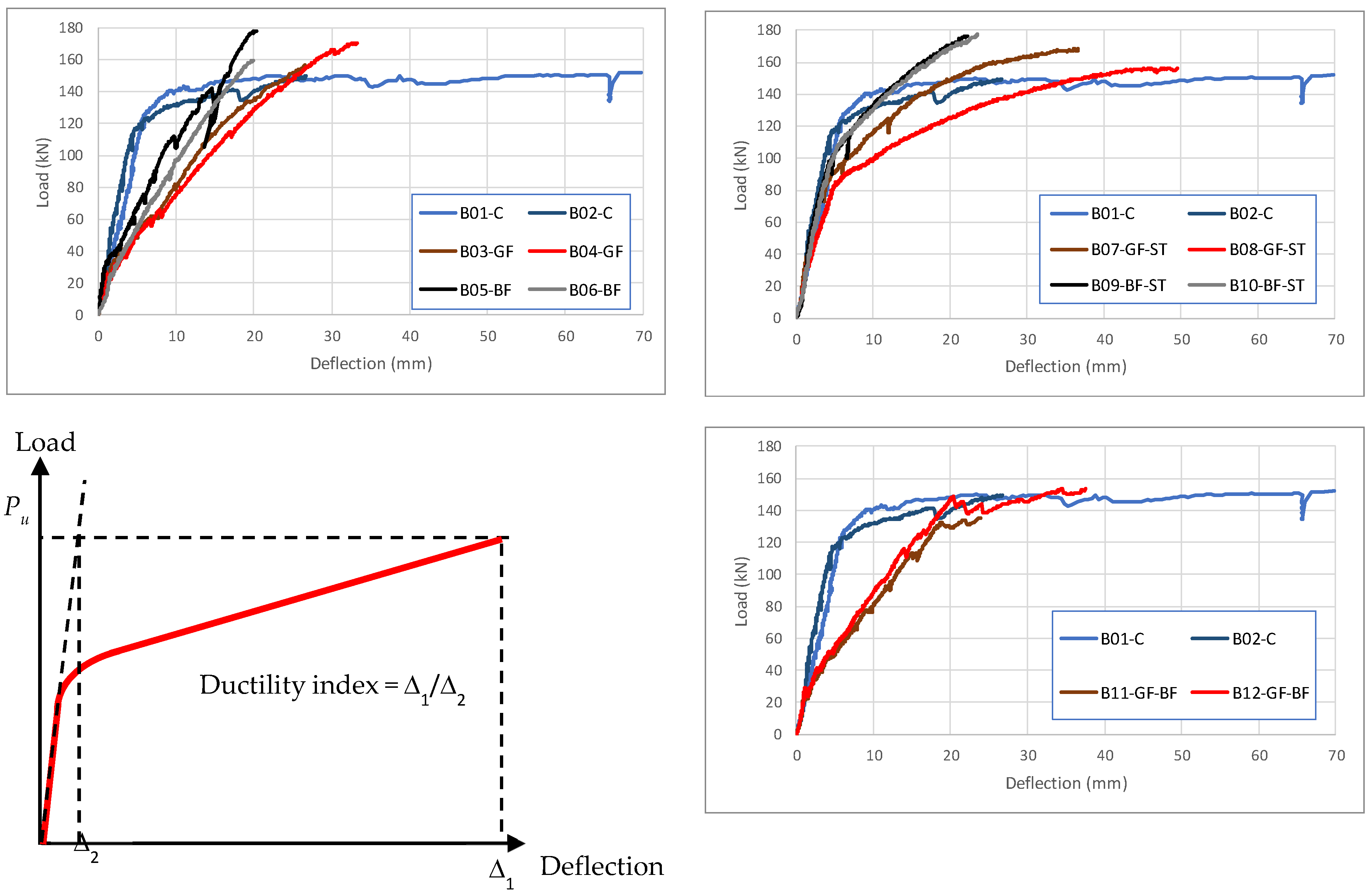
4.1. Cracking Moment and Load–Deflection Relations
4.2. Ductility
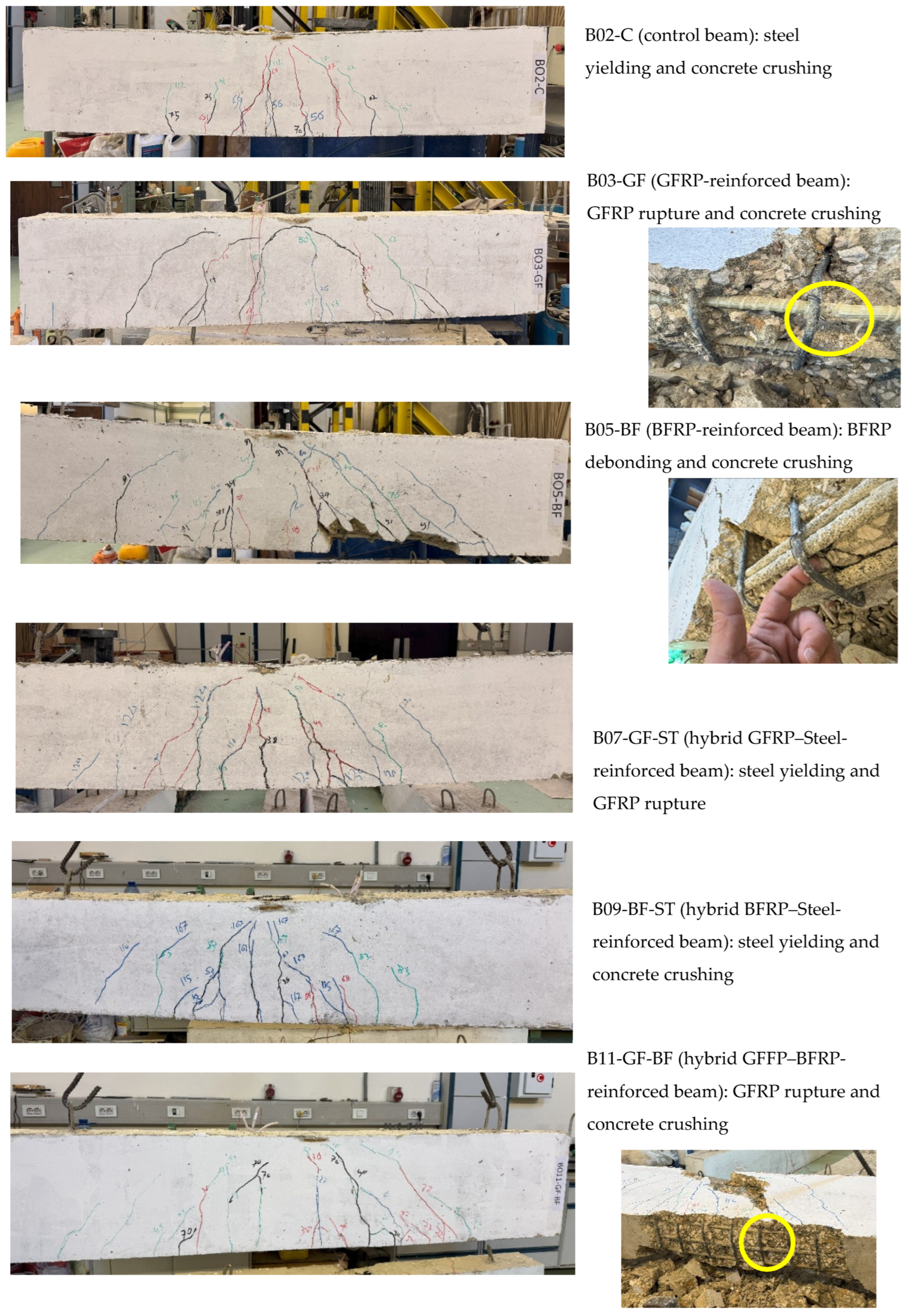
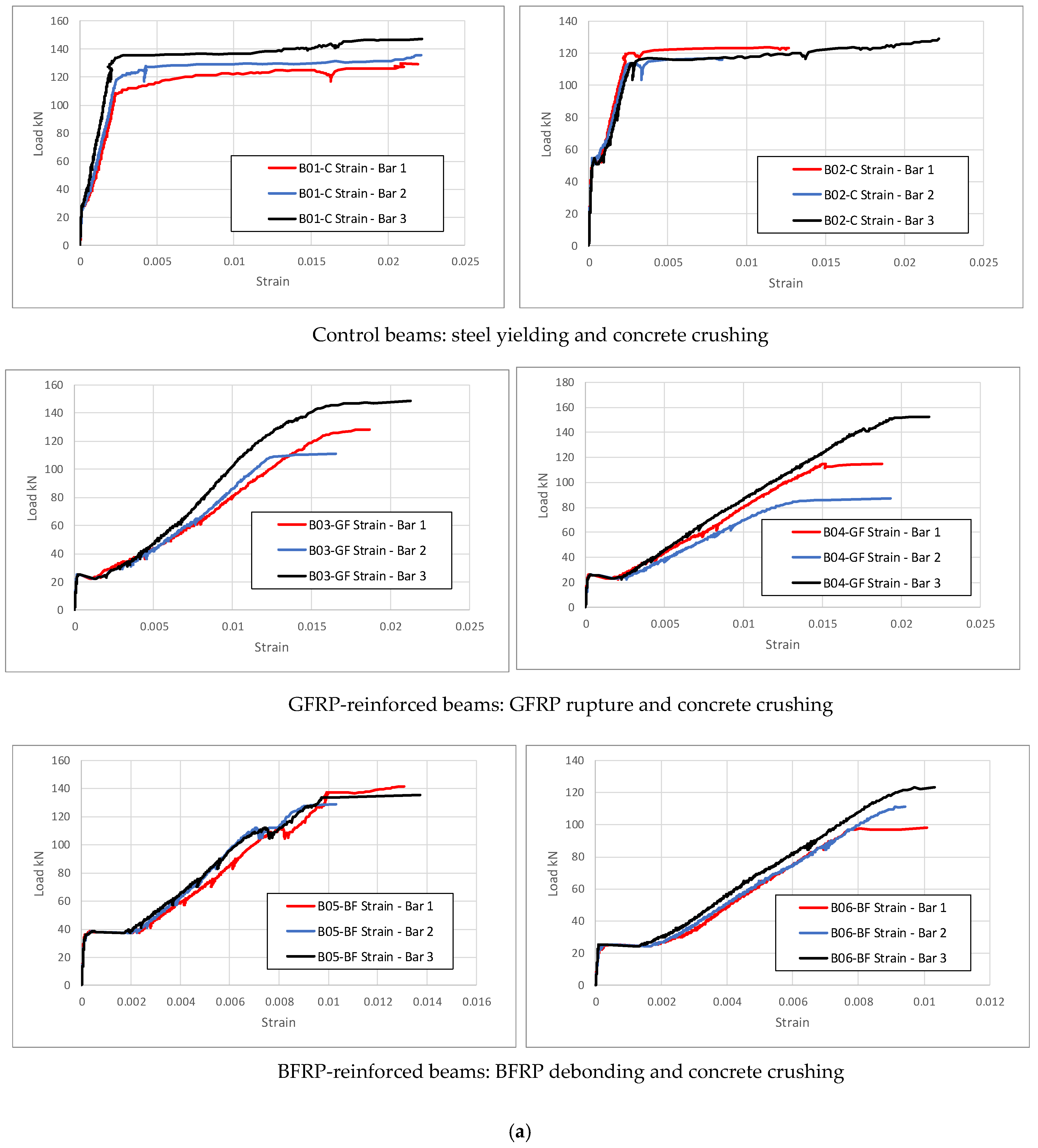
4.3. Failure Modes
4.4. Investigation Outcomes
- Load Capacity: GFRP- and BFRP-reinforced beams generally exhibited higher ultimate load capacity compared to steel-reinforced beams; 8% and 12%, respectively. Hybrid GFRP–Steel and BFRP–Steel-reinforced beams also show a higher load capacity compared to steel-reinforced beams; 8% and 17%, respectively. Hybrid GFRP–BFRP-reinforced beams do not improve the load capacity due to rupture of the BFRP bars.
- Deflection: GFRP- and BFRP-reinforced beams show significantly lower deflection at failure compared to steel-reinforced beams (62% and 42% of the steel-reinforced beams, respectively). Hybrid GFRP–Steel and BFRP–Steel-reinforced beams improve this behavior, where they show 90% and 48% of the steel-reinforced beams’ deflection.
- Failure Modes: GFRP-reinforced beams failed due to GFRP rupture, while BFRP beams experienced debonding or concrete crushing before rupture. Hybrid GFRP–Steel and BFRP–Steel-reinforced beams first exhibited steel yielding, followed by GFRP rupture for GFRP-reinforced beams or concrete crushing for BFRP-reinforced beams. All failure modes agree with those predicted analytically.
- Ductility: GFRP- and BFRP-reinforced beams exhibited lower ductility compared to steel-reinforced beams, as evidenced by their ductility indices; the ductility indices of steel-reinforced, GFRP-reinforced, and BFRP-reinforced beams are 7.4, 4.4, and 3.1, respectively. The ductility improves significantly for hybrid systems of GFRP–Steel and BFRP–Steel-reinforced beams; ductility indices are 8.0 and 4.7, respectively.
- Energy Absorption: The area under the load–deflection curve indicates energy absorption capacity and resistance to failure when subject to repeated or cyclic loading. Steel-reinforced beams show the highest area and a superior behavior to all other reinforced beams. The lowest areas are recorded for the GFRP-reinforced beams and the BFRP-reinforced beams (41% and 23% compared to steel-reinforced beams). The hybrid GFRP–Steel and BFRP–Steel reinforcement systems improve this behavior showing 64% and 41%, respectively, of the area under the load–deflection curve recorded for steel-reinforced beams.
- Anaytical and Experimental Failure Loads: Table 4 shows some discrepancies between the calculated and experimental failure loads for some beams. These differences can be explained by considering a few key mechanisms. The first is the material property variability, where analytical predictions are based on average values of the mechanical properties, whereas in practice, variability in material quality can affect actual performance. For instance, premature rupture or debonding in BFRP-reinforced beams may reduce the load-carrying capacity relative to the calculated values. The analytical model also assumes ideal bonding between the reinforcement and concrete. However, the experimental results, particularly for BFRP-reinforced beams, show signs of premature debonding, which may reduce the load capacity compared to the prediction. Furthermore, in some hybrid systems, load redistribution between reinforcement types may lead to failure modes that are not fully captured by conventional section analysis. For example, in the GFRP–BFRP hybrid beams, rupture of the BFRP bars occurred before reaching the predicted flexural capacity, thus lowering the actual failure load. Finally, the current ACI 440 guidelines may not fully capture the full behavior, interaction effects, or localized failure mechanisms seen in hybrid or BFRP-only systems. Overall, these discrepancies highlight the complexity of FRP and hybrid reinforcement behavior, reinforcing the need for further experimental validation and refinement of analytical models.
5. Conclusions
- Special consideration must be adopted in designing beams reinforced with GFRP or BFRP bars.
- A longer development length is required when using BFRP bars in reinforcing beams. This is not essentially required for GFRP-reinforced beams.
- Hybrid GFRP–Steel-reinforced beams showed significantly better ductility and increased toughness compared to GFRP-reinforced beams. Hybrid BFRP–Steel-reinforced beams also showed improved ductility relative to BFRP-reinforced beams, though not exceeding that of steel-only beams.
Author Contributions
Funding
Institutional Review Board Statement
Data Availability Statement
Conflicts of Interest
References
- Balakrishnan, P.; John, M.J.; Pothen, L.; Sreekala, M.S.; Thomas, S. Natural fibre and polymer matrix composites and their applications in aerospace engineering. In Advanced Composite Materials for Aerospace Engineering; Woodhead Publishing: Cambridge, UK, 2016; pp. 365–383. [Google Scholar] [CrossRef]
- Asim, M.; Saba, N.; Jawaid, M.; Nasir, M. Potential of natural fiber/biomass filler-reinforced polymer composites in aerospace applications. In Sustainable Composites for Aerospace Applications; Woodhead Publishing: Cambridge, UK, 2018; pp. 253–268. [Google Scholar] [CrossRef]
- Nanni, A. Flexural behavior and design of RC members using FRP reinforcement. J. Struct. Eng. 1993, 119, 44–59. [Google Scholar] [CrossRef]
- Benmokrane, B.; Xu, H.; Nishizaki, I. Aramid and carbon fibre-reinforced plastic prestressed ground anchors and their field applications. Can. J. Civ. Eng. 1997, 24, 968–985. [Google Scholar] [CrossRef]
- Daniel, I.M.; Ishai, O. Engineering Mechanics of Composite Materials; Oxford University Press Inc.: Oxford, UK, 1994. [Google Scholar]
- Sayed-Ahmed, E.Y.; Lissel, S.L.; Tadros, G.; Shrive, N.G. Carbon fibre reinforced polymer (CFRP) post-tensioned masonry diaphragm walls: Prestressing, behaviour, and design recommendations. Can. J. Civ. Eng. 1999, 26, 324–344. [Google Scholar] [CrossRef]
- Gudonis, E.; Timinskas, E.; Gribniak, V.; Kaklauskas, G.; Arnautov, A.K.; Tamulenas, V. FRP reinforcement for concrete structures: State-of-the-art review of application and design. Eng. Struct. Technol. 2013, 5, 147–158. [Google Scholar] [CrossRef]
- Kim, S.; Kim, S. Flexural behavior of concrete beams with steel bar and FRP reinforcement. J. Asian Archit. Build. Eng. 2019, 18, 89–97. [Google Scholar] [CrossRef]
- Hollaway, L.C. A review of the present and future utilization of FRP composites in the civil infrastructure with reference to their important in-service properties. Constr. Build. Mater. 2010, 24, 2419–2445. [Google Scholar] [CrossRef]
- Ovitigala, T. Structural Behavior of Concrete Beams Reinforced with Basalt Fiber Reinforced Polymer (BFRP) Bars. Ph.D. Dissertation, University of Illinois at Chicago, Chicago, IL, USA, 2012. [Google Scholar]
- Zaman, A.; Gutub, S.A.; Wafa, M.A. A review on FRP composites applications and durability concerns in the construction sector. J. Reinf. Plast. Compos. 2013, 32, 1966–1988. [Google Scholar] [CrossRef]
- Wang, X.; Li, L.; Wei, M.; Xiang, Y.; Wu, Y.; Zhou, B.; Sun, Y.; Cheng, W. Experimental study on the mechanical properties of short-cut basalt fiber reinforced concrete under large eccentric compression. Sci. Rep. 2025, 15, 10845. [Google Scholar] [CrossRef] [PubMed]
- Fiore, V.; Scalici, T.; Valenza, A.; Di Bella, G. A review on basalt fiber and its composites. Compos. Part. B Eng. 2015, 74, 74–94. [Google Scholar] [CrossRef]
- Du, H.; Xian, G.; Tian, J.; Ma, Z.; Li, C.; Xin, M.; Zhang, Y. Effect of fiber surface treatment with silane coupling agents and carbon nanotubes on mechanical properties of carbon fiber reinforced polyamide 6 composites. Polym. Compos. 2025, 46, 1267–1283. [Google Scholar] [CrossRef]
- Chen, J.; Teng, J. Experimental Investigation and Modeling of Deflection Prediction for Hybrid Fiber-Reinforced Polymer–Steel Concrete Beams. Adv. Struct. Eng. 2024, 27, 525–541. [Google Scholar] [CrossRef]
- Pareek, K.; Saha, P. Basalt fiber and its composites: An overview. In Proceedings of the National Conference on Advances in Structural Technologies (CoAST-2019), Assam, India, 1–3 February 2019; Volume 1, pp. 53–62. [Google Scholar]
- Al-Kharabsheh, B.N.; Arbili, M.M.; Majdi, A.; Alogla, S.M.; Hakamy, A.; Ahmad, J.; Deifalla, A.F. Basalt fiber reinforced concrete: A compressive review on durability aspects. Materials 2023, 16, 429. [Google Scholar] [CrossRef] [PubMed]
- Chen, J.F.; Teng, J.G. Shear capacity of FRP-strengthened RC beams: FRP debonding. Constr. Build. Mater. 2003, 15, 323–339. [Google Scholar] [CrossRef]
- Van Den Einde, L.; Zhao, L.; Seible, F. Use of FRP composites in civil structural applications. Constr. Build. Mater. 2003, 17, 389–403. [Google Scholar] [CrossRef]
- Guo, Z.; Wan, C.; Xu, M.; Chen, J. Review of Basalt Fiber Reinforced Concrete in China: Alkali Resistance of Fibers and Static Mechanical Properties of Composites. Adv. Mater. Sci. Eng. 2018, 1, 9198656. [Google Scholar] [CrossRef]
- Alhoubi, Y.; Mahaini, Z.; Abed, F. The flexural performance of BFRP-reinforced UHPC beams compared to steel and GFRP-reinforced beams. Sustainability 2022, 14, 15139. [Google Scholar] [CrossRef]
- Ascione, F.; Maselli, G.; Nesticò, A. Sustainable Materials Selection in Industrial Construction: A Life-Cycle based approach to compare the economic and structural performances of Glass Fibre Reinforced Polymer (GFRP) and Steel. J. Clean. Prod. 2024, 475, 143641. [Google Scholar] [CrossRef]
- ACI 440.6R-08; Specification for Carbon and Glass Fiber-Reinforced Polymer Bar Materials for Concrete Reinforcement. American Concrete Institute: Farmington Hills, MI, USA, 2008.
- ACI 440.1R-15; Guide for the Design and Construction of Structural Concrete Reinforced with Fiber-Reinforced Polymer Bars. American Concrete Institute: Farmington Hills, MI, USA, 2015.
- ACI 440.3R-12; Guide Test Methods for Fiber-Reinforced Polymer Composites for Reinforcing or Strengthening Concrete and Masonry Structures. American Concrete Institute: Farmington Hills, MI, USA, 2012.
- Tighiouart, B.; Benmokrane, B.; Gao, D. Investigation of bond in concrete member with fibre reinforced polymer (FRP) bars. Constr. Build. Mater. 1998, 12, 453–462. [Google Scholar] [CrossRef]
- Nepomuceno, E.; Sena-Cruz, J.; Correia, L.; D’Antino, T. Review on the bond behavior and durability of FRP bars to concrete. Constr. Build. Mater. 2021, 287, 123042. [Google Scholar] [CrossRef]
- Baena, M.; Torres, L.; Turon, A.; Barris, C. Experimental study of bond behaviour between concrete and FRP bars using a pull-out test. Compos. Part. B Eng. 2009, 40, 784–797. [Google Scholar] [CrossRef]
- Silva, E.M.; Ribeiro, S.E.; Diniz, S.M. Reliability-Based Design Recommendations for Deflection Control of Fiber-Reinforced Polymer-Reinforced Concrete Beams. ACI Struct. J. 2020, 117, 185–199. [Google Scholar] [CrossRef]
- Bischoff, P.H. Reevaluation of deflection prediction for concrete beams reinforced with steel and fiber reinforced polymer bars. J. Struc. Eng. 2005, 131, 752–767. [Google Scholar] [CrossRef]
- Bischoff, P.H.; Scanlon, A. Effective moment of inertia for calculating deflections of concrete members containing steel reinforcement and fiber-reinforced polymer reinforcement. ACI Struct. J. 2007, 104, 68. [Google Scholar] [CrossRef]
- Berg, A.C.; Bank, L.C.; Oliva, M.G.; Russell, J.S. Construction and cost analysis of an FRP reinforced concrete bridge deck. Constr. Build. Mater. 2006, 20, 515–526. [Google Scholar] [CrossRef]
- Yuan, F.; Chen, L.; Chen, M.; Xu, K. Behaviour of hybrid steel and FRP-reinforced concrete—ECC composite columns under reversed cyclic loading. Sensors 2018, 18, 4231. [Google Scholar] [CrossRef]
- Apinis, R.; Modniks, J.; Tamuzs, V.; Tepfers, R. Ductility of hybrid fiber composite Reinforcement FRP for concrete. In ECCM-8 European Conference on Composite Materials: Science, Technologies and Applications; Woodhead Publishing: Naples, Italy, 1998; Volume 2, p. 89. [Google Scholar]
- Mustafa, S.A.; Hassan, H.A. Behavior of concrete beams reinforced with hybrid steel and FRP composites. HBRC J. 2019, 14, 300–308. [Google Scholar] [CrossRef]
- Renic, T.; Hafner, I.; Kisicek, T. Ductility of hybrid FRP-steel reinforced concrete sections. In Proceedings of the 2nd International Conference CoMS 2020, Ljubljana, Slovenia, 20–21 April 2021; Volume 21, pp. 118–126. [Google Scholar]
- Aiello, M.A.; Ombres, L. Structural performances of concrete beams with hybrid (fiber-reinforced polymer-steel) reinforcements. J. Compos. Constr. 2002, 6, 754–762. [Google Scholar] [CrossRef]
- Badawy, M.M.; Anan, A.I.; Elkadi, O.A.; Sayed-Ahmed, E.Y. Flexural behavior of high strength concrete shallow wide beams reinforced by hybrid longitudinal reinforcement. HBRC J. 2024, 20, 205–230. [Google Scholar] [CrossRef]
- ACI 318-19; Building Code Requirements for Structural Concrete. American Concrete Institute: Farmington Hills, MI, USA, 2019.


| Beam | Bottom Reinf | Top Reinf | Stirrups | Length (m) | Dim (mm) | ||
|---|---|---|---|---|---|---|---|
| B01-C B02-C | 3 No. 12 | Steel | 2 No. 10 | Steel | No. 8@100 mm | 2.0 | 200 × 400 |
| B03-GF B04-GF | 3 No. 12 | GFRP | 2 No. 10 | Steel | No. 8@100 mm | 2.0 | 200 × 400 |
| B05-BF B06-BF | 3 No. 12 | BFRP | 2 No. 10 | Steel | No. 8@100 mm | 2.0 | 200 × 400 |
| B07-GF-ST B08-GF-BF | 2 No. 12 1 No. 12 | Steel GFRP | 2 No. 10 | Steel | No. 8@100 mm | 2.0 | 200 × 400 |
| B09-BF-ST B10-BF-ST | 2 No. 12 1 No. 12 | Steel BFRP | 2 No. 10 | Steel | No. 8@100 mm | 2.0 | 200 × 400 |
| B11-GF-BF B12-GF-BF | 2 No. 12 1 No. 12 | GFRP BFRP | 2 No. 10 | Steel | No. 8@100 mm | 2.0 | 200 × 400 |
| Material | Property | Value |
|---|---|---|
| Concrete | 28d compressive strength: fc/ | 25 MPa |
| Crushing strains εcu | 0.003 | |
| Initial elastic modulus Ec = 4700 (fc/)1/2 | 23.5 GPa | |
| α1 and β1 | 0.85, 0.85 | |
| Steel bars | Yield stress Fy-s—reinforcement bars Yield stress Fy-v—stirrups | 465 MPa 360 MPa |
| Elastic modulus Es | 200 GPa | |
| Yield strain εy-s—reinforcement bars Yield strain εy-v—stirrups | 0.0023 0.0018 | |
| GFRP bars | Tensile strength Fu-GFRP | 483–690 MPa |
| Elastic modulus EGFRP | 35–61 GPa | |
| Rupture strain εu-GFRP | 0.01–0.031 | |
| BFRP bars | Tensile strength Fu-BFRP | 600–1700 |
| Elastic modulus EBFRP | 50–90 GPa | |
| Rupture strain εu-BFRP | 0.018–0.032 |
| Beam | Nominal Moment Mn (kN·m) | Expected Failure Load Pu-M (kN) | Failure Mode Analytically Predicted | Nominal Shear Vn (kN) | Expected Failure Load Pu-V (kN) |
|---|---|---|---|---|---|
| B01-C B02-C | 55.5 | 120 | Steel yield—Conc crushing | 197 | 393 |
| B03-GF B04-GF | 80.9 | 175 | GFRP rupture—Conc crushing | 154 | 308 |
| B05-BF B06-BF | 92.9 | 201 | Conc crushing | 157 | 314 |
| B07-GF-ST B08-GF-ST | 62.4 | 135 | Steel yield—GFRP rupture | 197 | 393 |
| B09-BF-ST B10-BF-ST | 76.7 | 166 | Steel yield—Conc crushing | 197 | 393 |
| B11-GF-BF B12-GF-BF | 92.1 | 199 | GFRP rupture—Conc crushing | 197 | 393 |
| Beam | Calc. Failure Load (kN) | Expected Failure Mode | Experimental Failure Load (kN) | Deflection at Failure (mm) | Observed Failure Mode | Capacity Increase% | ||
|---|---|---|---|---|---|---|---|---|
| 0B01-C B02-C | 120 | Steel yield—Conc crushing | 152.2 149.5 | 150.8 ± 1.9 | 69.8 26.5 | 48.2 ± 30.6 | Steel yield—Conc crushing | -- |
| B03-GF B04-GF | 175 | GFRP rupture—Conc crushing | 156.4 170.6 | 163.5 ± 10.1 | 26.6 33.2 | 29.9 ± 4.7 | GFRP rupture—Conc crushing | 8% |
| B05-BF B06-BF | 201 | Conc crushing | 178.2 159.5 | 168.9 ± 13.2 | 20.4 19.9 | 20.2 ± 0.4 | BFRP debond—Conc crushing | 12% |
| B07-GF-ST B08-GF-ST | 135 | Steel yield—GFRP rupture | 168.7 156.4 | 162.6 ± 8.7 | 36.7 49.5 | 43.1 ± 9.1 | Steel yield—GFRP rupture | 8% |
| B09-BF-ST B10-BF-ST | 166 | Steel yield—Conc crushing | 176.3 177.5 | 179.9 ± 0.85 | 22.3 23.6 | 23.0 ± 0.9 | Steel yield—Conc crushing | 17% |
| B11-GF-BF B12-GF-BF | 199 | GFRP rupture—Conc crushing | 135.4 153.7 | 144.6 ± 12.9 | 23.8 37.5 | 30.7 ± 9.7 | GFRP rupture—Conc crushing | −4% |
| Beam | Δ1 (mm) | Δ2 (mm) | DI = Δ1/Δ2 | A (kN·m) | A/Acontrol | |||
|---|---|---|---|---|---|---|---|---|
| 0B01-C B02-C | 70 26.5 | 48.3 ± 30.8 | 8.0 5.1 | 6.6 ± 2.1 | 7.4 | 11.03 3.29 | 7.2 ± 5.5 | 1.00 |
| B03-GF B04-GF | 26.7 33.1 | 29.9 ± 4.5 | 6 7.6 | 6.8 ± 1.1 | 4.4 | 2.52 3.37 | 2.9 ± 0.6 | 0.41 |
| B05-BF B06-BF | 20.5 20 | 20.3 ± 0.4 | 4.5 8.4 | 6.5 ± 2.8 | 3.1 | 2.11 1.22 | 1.7 ± 0.63 | 0.23 |
| B07-GF-ST B08-GF-ST | 36.8 49.8 | 43.3 ± 9.2 | 4.6 6.2 | 5.4 ± 1.1 | 8.0 | 3.29 5.92 | 4.6 ± 1.9 | 0.64 |
| B09-BF-ST B10-BF-ST | 22.4 23.8 | 23.1 ± 1.0 | 3.7 6.2 | 5.0 ± 1.8 | 4.7 | 2.91 3.02 | 2.9 ± 0.1 | 0.41 |
| B11-GF-BF B12-GF-BF | 23.8 23.7 | 23.8 ± 0.07 | 5.1 6.5 | 5.8 ± 1.0 | 4.1 | 2.16 4.38 | 3.3 ± 1.6 | 0.45 |
Disclaimer/Publisher’s Note: The statements, opinions and data contained in all publications are solely those of the individual author(s) and contributor(s) and not of MDPI and/or the editor(s). MDPI and/or the editor(s) disclaim responsibility for any injury to people or property resulting from any ideas, methods, instructions or products referred to in the content. |
© 2025 by the authors. Licensee MDPI, Basel, Switzerland. This article is an open access article distributed under the terms and conditions of the Creative Commons Attribution (CC BY) license (https://creativecommons.org/licenses/by/4.0/).
Share and Cite
Elbawab, Y.; Elbawab, Y.; El Zoughby, Z.; ElKadi, O.; AbouZeid, M.; Sayed-Ahmed, E. Flexural Testing of Steel-, GFRP-, BFRP-, and Hybrid Reinforced Beams. Polymers 2025, 17, 2027. https://doi.org/10.3390/polym17152027
Elbawab Y, Elbawab Y, El Zoughby Z, ElKadi O, AbouZeid M, Sayed-Ahmed E. Flexural Testing of Steel-, GFRP-, BFRP-, and Hybrid Reinforced Beams. Polymers. 2025; 17(15):2027. https://doi.org/10.3390/polym17152027
Chicago/Turabian StyleElbawab, Yazeed, Youssef Elbawab, Zeina El Zoughby, Omar ElKadi, Mohamed AbouZeid, and Ezzeldin Sayed-Ahmed. 2025. "Flexural Testing of Steel-, GFRP-, BFRP-, and Hybrid Reinforced Beams" Polymers 17, no. 15: 2027. https://doi.org/10.3390/polym17152027
APA StyleElbawab, Y., Elbawab, Y., El Zoughby, Z., ElKadi, O., AbouZeid, M., & Sayed-Ahmed, E. (2025). Flexural Testing of Steel-, GFRP-, BFRP-, and Hybrid Reinforced Beams. Polymers, 17(15), 2027. https://doi.org/10.3390/polym17152027