

Electrospun PANI/PEO-Luffa Cellulose/TiO2 Nanofibers: A Sustainable Biocomposite for Conductive Applications
Abstract
1. Introduction
2. Materials and Methods
2.1. Materials
2.2. Alkali Treatment of Luffa Fibers and Preparation of Biocomposites
2.3. Electrospinning for Nanofiber Formation
2.4. Instrumentations
3. Results and Discussion
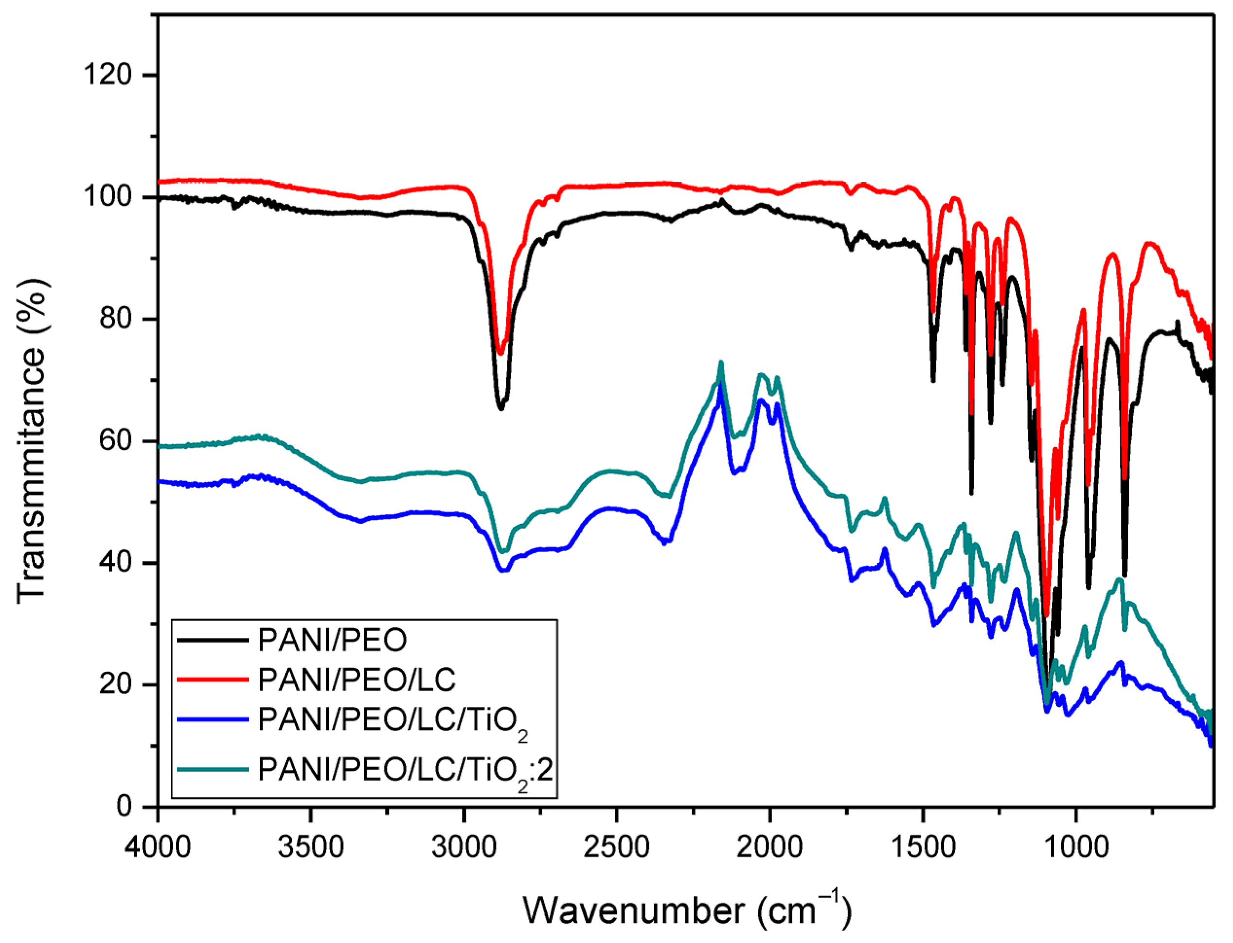
3.1. FT-IR Spectra
3.2. XRD Analysis
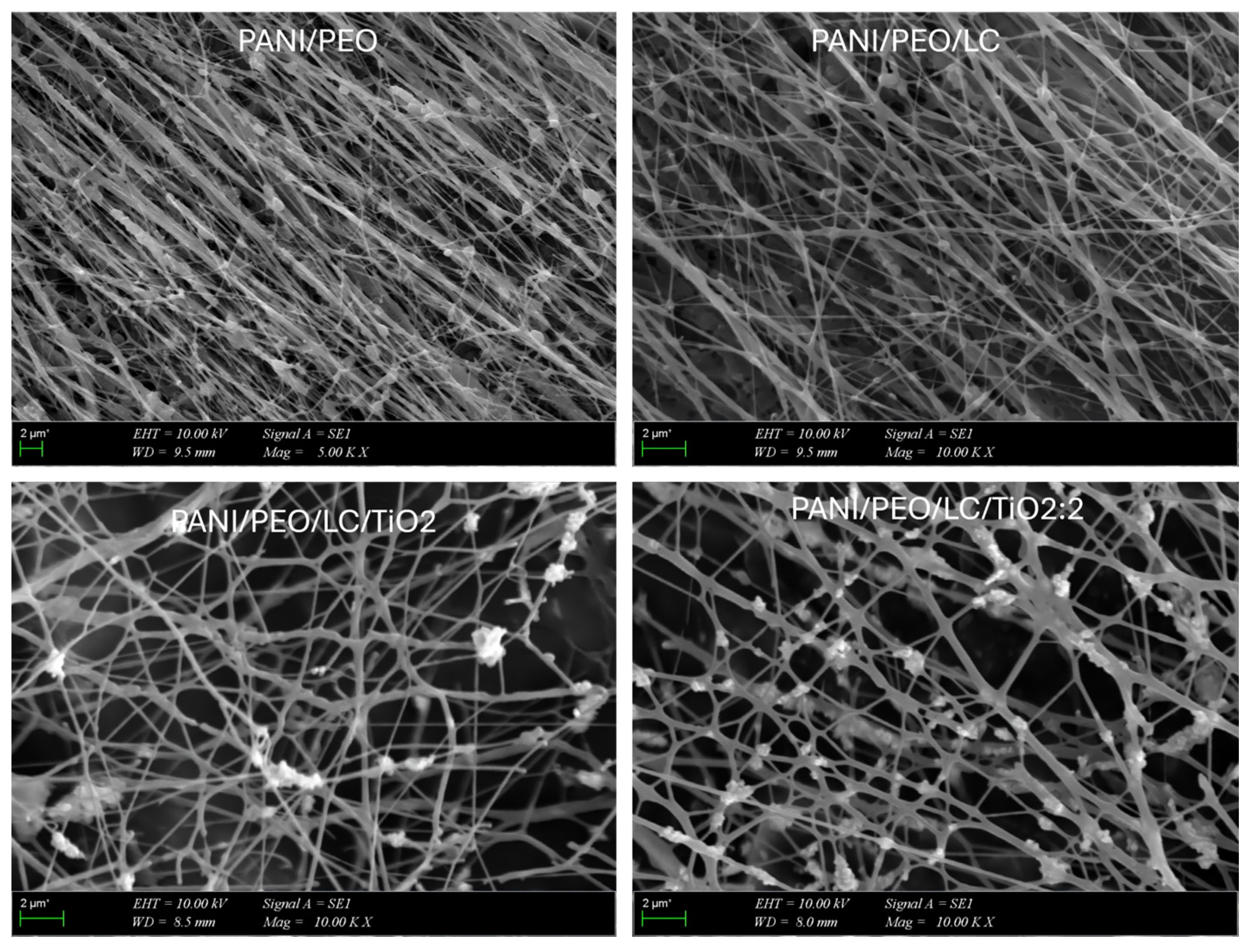
3.3. SEM Images
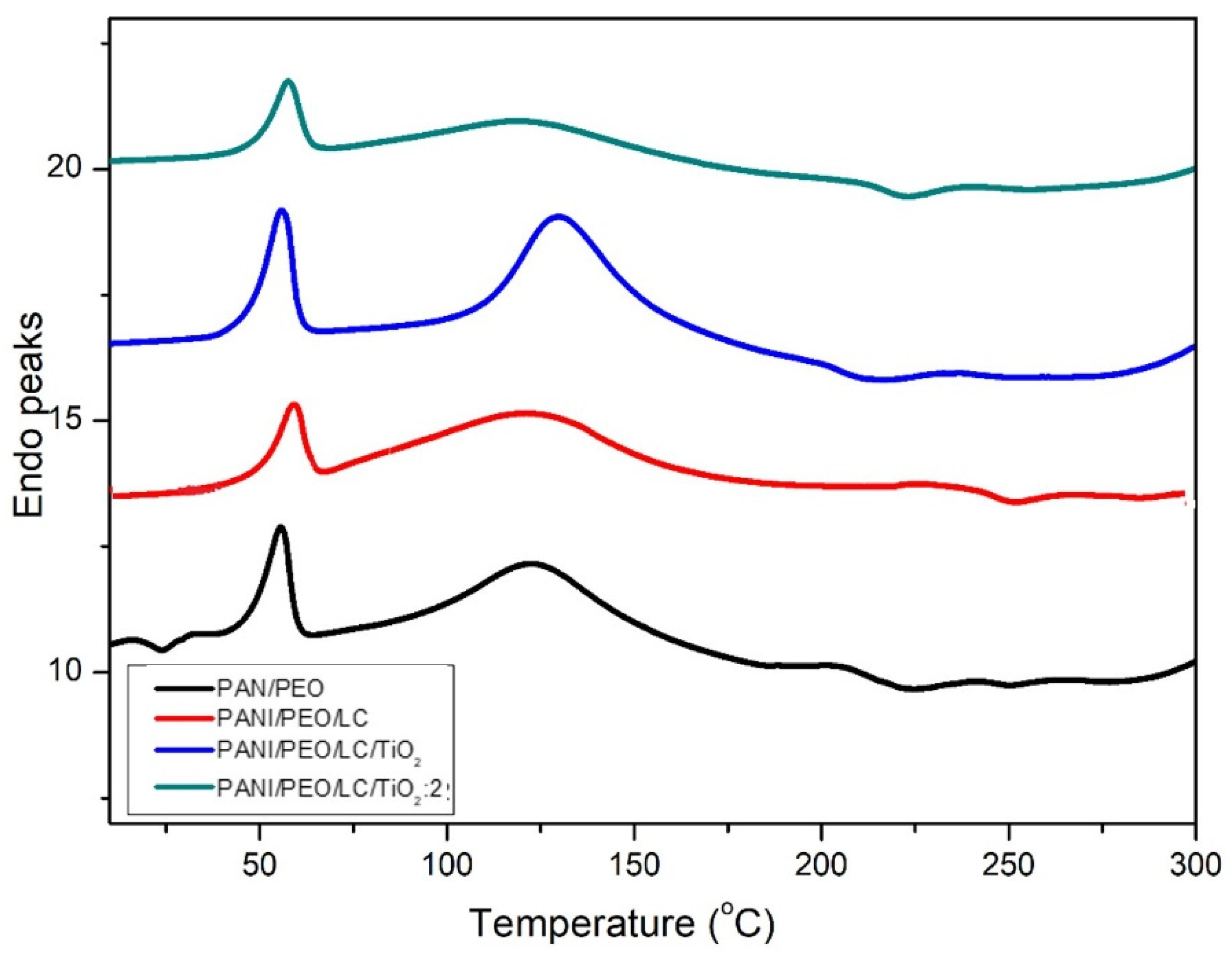
3.4. DSC Analyses
3.5. TGA Analysis
4. Conclusions
Author Contributions
Funding
Data Availability Statement
Conflicts of Interest
References
- Priyanka; Yadav, D.; Dutta, J. Switching to Bioplastics for Sustaining Our Environment. In Environmental Biotechnology Volume 4; Gothandam, K.M., Srinivasan, R., Ranjan, S., Dasgupta, N., Lichtfouse, E., Eds.; Springer International Publishing: Cham, Switzerland, 2021; pp. 1–45. ISBN 978-3-030-77795-1. [Google Scholar]
- Zhang, J.; Chen, K.; Ding, C.; Sun, S.; Zheng, Y.; Ding, Q.; Hong, B.; Liu, W. Fabrication of Chitosan/PVP/Dihydroquercetin Nanocomposite Film for In Vitro and In Vivo Evaluation of Wound Healing. Int. J. Biol. Macromol. 2022, 206, 591–604. [Google Scholar] [CrossRef] [PubMed]
- Brischetto, S. Analysis of Natural Fibre Composites for Aerospace Structures. Aircr. Eng. Aerosp. Technol. 2018, 90, 1372–1384. [Google Scholar] [CrossRef]
- Chandgude, S.; Salunkhe, S. In State of Art: Mechanical Behavior of Natural Fiber-Based Hybrid Polymeric Composites for Application of Automobile Components. Polym. Compos. 2021, 42, 2678–2703. [Google Scholar] [CrossRef]
- Rahman, N.S.A.; Yhaya, M.F.; Azahari, B.; Ismail, W.R. Utilisation of Natural Cellulose Fibres in Wastewater Treatment. Cellulose 2018, 25, 4887–4903. [Google Scholar] [CrossRef]
- Kóczán, Z.; Pásztory, Z. Overview of Natural Fiber-Based Packaging Materials. J. Nat. Fibers 2024, 21, 2301364. [Google Scholar] [CrossRef]
- Chen, Y.; Su, N.; Zhang, K.; Zhu, S.; Zhu, Z.; Qin, W.; Yang, Y.; Shi, Y.; Fan, S.; Wang, Z.; et al. Effect of Fiber Surface Treatment on Structure, Moisture Absorption and Mechanical Properties of Luffa Sponge Fiber Bundles. Ind. Crops Prod. 2018, 123, 341–352. [Google Scholar] [CrossRef]
- Escocio, V.A.; Visconte, L.L.Y.; Cavalcante, A.d.P.; Furtado, A.M.S.; Pacheco, E.B.A.V. Study of Mechanical and Morphological Properties of Bio-Based Polyethylene (HDPE) and Sponge-Gourds (Luffa-cylindrica) Agroresidue Composites. In Proceedings of the PPS-30: The 30th International Conference of the Polymer Processing Society; Jana, S.C., Ed.; Amer Inst Physics: Melville, WA, Australia, 2015; Volume 1664, p. 060012. [Google Scholar]
- Genc, G.; Ozdemir, Y. Improvement of the Mechanical Properties of Plant Fiber-reinforced Composites through Hybridization. J. Nat. Fibers 2022, 19, 2805–2812. [Google Scholar] [CrossRef]
- Akgül, M.; Korkut, S.; Çamlıbel, O.; Ayata, Ü. Some Chemical Properties of Luffa and Its Suitability for Medium Density Fiberboard (MDF) Production: BioResources. Available online: https://bioresources.cnr.ncsu.edu/ (accessed on 7 May 2024).
- Li, S.; Tao, M.; Xie, Y. Reduced Graphene Oxide Modified Luffa Sponge as a Biocomposite Adsorbent for Effective Removal of Cationic Dyes from Aqueous Solution. Desalination Water Treat. 2016, 57, 20049–20057. [Google Scholar] [CrossRef]
- Akay, O.; Altinkok, C.; Acik, G.; Yuce, H.; Ege, G.K.; Genc, G. Preparation of a Sustainable Bio-Copolymer Based on Luffa cylindrica Cellulose and Poly(ε-caprolactone) for Bioplastic Applications. Int. J. Biol. Macromol. 2022, 196, 98–106. [Google Scholar] [CrossRef] [PubMed]
- Halashi, K.; Taban, E.; Soltani, P.; Amininasab, S.; Samaei, E.; Moghadam, D.N.; Khavanin, A. Acoustic and thermal performance of luffa fiber panels for sustainable building applications. Build. Environ. 2024, 247, 111051. [Google Scholar] [CrossRef]
- Koruk, H.; Genc, G. Investigation of the Acoustic Properties of Bio Luffa Fiber and Composite Materials. Mater. Lett. 2015, 157, 166–168. [Google Scholar] [CrossRef]
- Alhijazi, M.; Safaei, B.; Zeeshan, Q.; Asmael, M.; Eyvazian, A.; Qin, Z. Recent Developments in Luffa Natural Fiber Composites: Review. Sustainability 2020, 12, 7683. [Google Scholar] [CrossRef]
- Ghali, L.; Msahli, S.; Zidi, M.; Sakli, F. Effect of Pre-Treatment of Luffa fibres on the Structural Properties. Mater. Lett. 2009, 63, 61–63. [Google Scholar] [CrossRef]
- Melo, B.N.; Dos-Santos, C.G.; Botaro, V.R.; Pasa, V.M.D. Eco-Composites of Polyurethane and Luffa Aegyptiaca Modified by Mercerisation and Benzylation. Polym. Polym. Compos. 2008, 16, 249–256. [Google Scholar] [CrossRef]
- Choi, K.-S.; Kim, Y.-H.; Kim, S.-O.; Shin, K.-O.; Chung, K.-H. Effect of Intake of Sponge Gourd (Luffa cylindrica) Seed Oil and Yukdomok (Chionanthus retusa L.) Seed Oil on Lipid Levels of Blood and Organs of a Mice. Food Sci. Biotechnol. 2013, 22, 757–763. [Google Scholar] [CrossRef]
- Roble, N.; Ogbonna, J.; Tanaka, H. A Novel Circulating Loop Bioreactor with Cells Immobilized in Loofa (Luffa cylindrica) Sponge for the Bioconversion of Raw Cassava Starch to Ethanol. Appl. Microbiol. Biotechnol. 2003, 60, 671–678. [Google Scholar] [CrossRef] [PubMed]
- Ahmadi, M.; Vahabzadeh, F.; Bonakdarpour, B.; Mehranian, M. Empirical modeling of olive oil mill wastewater treatment using loofa-immobilized Phanerochaete chrysosporium. Process Biochem. 2006, 41, 1148–1154. [Google Scholar] [CrossRef]
- Shen, J.; Xie, Y.M.; Huang, X.; Zhou, S.; Ruan, D. Behaviour of Luffa Sponge Material Under Dynamic Loading. Int. J. Impact Eng. 2013, 57, 17–26. [Google Scholar] [CrossRef]
- Tran, H.D.; Li, D.; Kaner, R.B. One-Dimensional Conducting Polymer Nanostructures: Bulk Synthesis and Applications. Adv. Mater. 2009, 21, 1487–1499. [Google Scholar] [CrossRef]
- Kuchibhatla, S.V.N.T.; Karakoti, A.S.; Bera, D.; Seal, S. One Dimensional Nanostructured Materials. Prog. Mater. Sci. 2007, 52, 699–913. [Google Scholar] [CrossRef]
- Wang, X.-X.; Yu, G.-F.; Zhang, J.; Yu, M.; Ramakrishna, S.; Long, Y.-Z. Conductive Polymer Ultrafine Fibers via Electrospinning: Preparation, Physical Properties and Applications. Prog. Mater. Sci. 2021, 115, 100704. [Google Scholar] [CrossRef]
- Zhang, C.; Yuan, X.; Wu, L.; Han, Y.; Sheng, J. Study on Morphology of Electrospun Poly(vinyl alcohol) Mats. Eur. Polym. J. 2005, 41, 423–432. [Google Scholar] [CrossRef]
- Chase, G.G.; Reneker, D.H. Nanofibers in Filter Media. Fluid Part. Sep. J. 2004, 16, 105–117. [Google Scholar]
- Wu, H.; Pan, W.; Lin, D.; Li, H. Electrospinning of Ceramic Nanofibers: Fabrication, Assembly and Applications. J. Adv. Ceram. 2012, 1, 2–23. [Google Scholar] [CrossRef]
- Chang, C.-L.; Liang, J.-W.; Chen, W.; Fu, S.-L. Preparation of Fluorescent Ceramic Nanofibers by Electrospinning and Heat Treatment. In Proceedings of the 2016 International Conference on Electronics Packaging (ICEP), Hokkaido, Japan, 20–22 April 2016; pp. 681–684. [Google Scholar]
- Suphankij, S.; Mekprasart, W.; Pecharapa, W. Photocatalytic of N-doped TiO2 Nanofibers Prepared by Electrospinning. Energy Procedia 2013, 34, 751–756. [Google Scholar] [CrossRef]
- Razavi, F.S.; Ghanbari, D.; Dawi, E.A.; Salavati-Niasari, M. Electrospun bimetallic Au–Pt/TiO2/BaFe12O19 Nanofibers as Promising Photocatalysts Driven by Visible Light: SYNTHESIS and Characterization. J. Sci. Adv. Mater. Devices 2023, 8, 100559. [Google Scholar] [CrossRef]
- Park, J.-A.; Moon, J.; Lee, S.-J.; Lim, S.-C.; Zyung, T. Fabrication and Characterization of ZnO Nanofibers by Electrospinning. Curr. Appl. Phys. 2009, 9, S210–S212. [Google Scholar] [CrossRef]
- Praeger, M.; Saleh, E.; Vaughan, A.; Stewart, W.J.; Loh, W.H. Fabrication of Nanoscale Glass Fibers by Electrospinning. Appl. Phys. Lett. 2012, 100, 063114. [Google Scholar] [CrossRef]
- Chichane, A.; Boujmal, R.; El Barkany, A. Bio-Composites and Bio-Hybrid Composites Reinforced with Natural Fibers: Review. Mater. Today Proc. 2023, 72, 3471–3479. [Google Scholar] [CrossRef]
- Tong, L.; Wang, X.-X.; He, X.-X.; Nie, G.-D.; Zhang, J.; Zhang, B.; Guo, W.-Z.; Long, Y.-Z. Electrically Conductive TPU Nanofibrous Composite with High Stretchability for Flexible Strain Sensor. Nanoscale Res. Lett. 2018, 13, 86. [Google Scholar] [CrossRef] [PubMed]
- Konuk Ege, G.; Akay, Ö.; Yüce, H. A Chemosensitive Based Ammonia Gas Sensor with PANI/PEO-ZnO Nanofiber Composites Sensing Layer. Microelectron. Int. 2023. [Google Scholar] [CrossRef]
- Shiu, B.-C.; Liu, Y.-L.; Yuan, Q.-Y.; Lou, C.-W.; Lin, J.-H. Preparation and Characterization of PEDOT:PSS/TiO2 Micro/Nanofiber-Based Gas Sensors. Polymers 2022, 14, 1780. [Google Scholar] [CrossRef] [PubMed]
- Kim, T.; Yang, S.J.; Sung, S.J.; Kim, Y.S.; Chang, M.S.; Jung, H.; Park, C.R. Highly Reproducible Thermocontrolled Electrospun Fiber Based Organic Photovoltaic Devices. ACS Appl. Mater. Interfaces 2015, 7, 4481–4487. [Google Scholar] [CrossRef] [PubMed]
- Wang, H.; Lin, J.; Shen, Z.X. Polyaniline (PANi) Based Electrode Materials for Energy Storage and Conversion. J. Sci. Adv. Mater. Devices 2016, 1, 225–255. [Google Scholar] [CrossRef]
- Tanzifi, M.; Kolbadi Nezhad, M.; Karimipour, K. Kinetic and Isotherm Studies of Cadmium Adsorption on Polypyrrole/Titanium dioxide Nanocomposite. J. Water Environ. Nanotechnol. 2017, 2, 265–277. [Google Scholar] [CrossRef]
- Shi, L.; Wang, X.; Lu, L.; Yang, X.; Wu, X. Preparation of TiO2/Polyaniline Nanocomposite from a Lyotropic Liquid Crystalline Solution. Synth. Met. 2009, 159, 2525–2529. [Google Scholar] [CrossRef]
- AL-Oqla, F.M.; Sapuan, S.M.; Anwer, T.; Jawaid, M.; Hoque, M.E. Natural Fiber Reinforced Conductive Polymer Composites as Functional Materials: A review. Synth. Met. 2015, 206, 42–54. [Google Scholar] [CrossRef]
- Yazıcı, P.; Alkhateab, B.; Sezer, E.; Koçak, D.; Ustamehmetoğlu, B. Synthesize and Characterization of Sustainable Natural Fibers/ Conductive Polymer Composites. J. Ind. Text. 2022, 51, 8338S–8361S. [Google Scholar] [CrossRef]
- Rathore, B.S.; Chauhan, N.P.S.; Jadoun, S.; Ameta, S.C.; Ameta, R. Synthesis and Characterization of Chitosan-Polyaniline-Nickel(II) Oxide Nanocomposite. J. Mol. Struct. 2021, 1242, 130750. [Google Scholar] [CrossRef]
- Silva, A.L.C.; Ugucioni, J.C.; Correa, S.; Ardisson, J.D.; Macedo, W.A.A.; Silva, J.P.; Cotta, A.A.C.; Brito, A.D.B. Synthesis and Characterization of Nanocomposites Consisting of Polyaniline, Chitosan and Tin Dioxide. Mater. Chem. Phys. 2018, 216, 402–412. [Google Scholar] [CrossRef]
- Shi, Y.; Li, Z.; Shi, J.; Zhang, F.; Zhou, X.; Li, Y.; Holmes, M.; Zhang, W.; Zou, X. Titanium Dioxide-Polyaniline/Silk Fibroin Microfiber Sensor for Pork Freshness Evaluation. Sens. Actuators B Chem. 2018, 260, 465–474. [Google Scholar] [CrossRef]
- Ege, G.K.; Yuce, H.; Akay, O.; Oner, H.; Genc, G. A Fabrication and Characterization of Luffa/PANI/PEO Biocomposite Nanofibers by Means of Electrospinning. Pigment. Resin.Technol. 2023, 52, 151–159. [Google Scholar] [CrossRef]
- Al-Hazeem, N.Z.; Ahmed, N.M. Effect of Addition of Polyaniline on Polyethylene Oxide and Polyvinyl Alcohol for the Fabrication of Nanorods. ACS Omega 2020, 5, 22389–22394. [Google Scholar] [CrossRef] [PubMed]
- Mansor, E.S.; Ali, H.; Abdel-Karim, A. Efficient and Reusable Polyethylene Oxide/Polyaniline Composite Membrane for Dye Adsorption and Filtration. Colloid Interface Sci. Commun. 2020, 39, 100314. [Google Scholar] [CrossRef]
- Sujith, K.; Asha, A.M.; Anjali, P.; Sivakumar, N.; Subramanian, K.R.V.; Nair, S.V.; Balakrishnan, A. Fabrication of Highly Porous Conducting PANI-C Composite Fiber Mats via Electrospinning. Mater. Lett. 2012, 67, 376–378. [Google Scholar] [CrossRef]
- Hajlaoui, O.; Khiari, R.; Ajili, L.; Batis, N.; Bergaoui, L. Design and Characterization of Type I Cellulose-Polyaniline Composites from Various Cellulose Sources: A Comparative Study. Chem. Afr. 2020, 3, 783–792. [Google Scholar] [CrossRef]
- Biswas, S.; Rahaman, T.; Gupta, P.; Mitra, R.; Dutta, S.; Kharlyngdoh, E.; Guha, S.; Ganguly, J.; Pal, A.; Das, M. Cellulose and Lignin Profiling in Seven, Economically Important Bamboo Species of India by Anatomical, Biochemical, FTIR Spectroscopy and Thermogravimetric Analysis. Biomass Bioenergy 2022, 158, 106362. [Google Scholar] [CrossRef]
- Nepomuceno, N.C.; Seixas, A.A.A.; Medeiros, E.S.; Mélo, T.J.A. Evaluation of Conductivity of Nanostructured Polyaniline/Cellulose Nanocrystals (PANI/CNC) Obtained via in Situ Polymerization. J. Solid. State Chem. 2021, 302, 122372. [Google Scholar] [CrossRef]
- Sasikumar, M.; Subiramaniyam, N.P. Microstructure, Electrical and Humidity Sensing Properties of TiO2/Polyaniline Nanocomposite Films Prepared by Sol–Gel Spin Coating Technique. J. Mater. Sci Mater. Electron. 2018, 29, 7099–7106. [Google Scholar] [CrossRef]
- Truong, D.H.; Dam, M.S.; Bujna, E.; Rezessy-Szabo, J.; Farkas, C.; Vi, V.N.H.; Csernus, O.; Nguyen, V.D.; Gathergood, N.; Friedrich, L.; et al. In situ Fabrication of Electrically Conducting Bacterial Cellulose-Polyaniline-Titanium-Dioxide Composites with the Immobilization of Shewanella xiamenensis and its Application as Bioanode in Microbial Fuel Cell. Fuel 2021, 285, 119259. [Google Scholar] [CrossRef]
- Amalraj, J.; Mahadeva, S.; Kim, J. The Preparation, Characterization and Actuation Behavior of Polyaniline and Cellulose Blended Electro-Active Paper. Smart Mater. Struct. 2010, 19, 045011. [Google Scholar] [CrossRef]
- Kwon, M.; Kim, J.; Kim, J. Photocatalytic Activity and Filtration Performance of Hybrid TiO2-Cellulose Acetate Nanofibers for Air Filter Applications. Polymers 2021, 13, 1331. [Google Scholar] [CrossRef] [PubMed]
- Nkabinde, S.C.; Moloto, M.J.; Matabola, K.P. Optimized Loading of TiO2 Nanoparticles into Electrospun Polyacrylonitrile and Cellulose Acetate Polymer Fibers. J. Nanomater. 2020, 2020, 9429421. [Google Scholar] [CrossRef]
- Pang, Z.; Fu, J.; Luo, L.; Huang, F.; Wei, Q. Fabrication of PA6/TiO2/PANI Composite Nanofibers by Electrospinning-Electrospraying for Ammonia Sensor. Colloids Surf. A Physicochem. Eng. Asp. 2014, 461, 113–118. [Google Scholar] [CrossRef]
- Sulowska, A.; Wysocka, I.; Pelczarski, D.; Karczewski, J.; Zielińska-Jurek, A. Hybrid TiO2–Polyaniline Photocatalysts and their Application in Building Gypsum Plasters. Materials 2020, 13, 1516. [Google Scholar] [CrossRef] [PubMed]
- Rošic, R.; Pelipenko, J.; Kocbek, P.; Baumgartner, S.; Bešter-Rogač, M.; Kristl, J. The Role of Rheology of Polymer Solutions in Predicting Nanofiber Formation by Electrospinning. Eur. Polym. J. 2012, 48, 1374–1384. [Google Scholar] [CrossRef]
- Khan, M.Q.; Kharaghani, D.; Ullah, S.; Waqas, M.; Abbasi, A.M.R.; Saito, Y.; Zhu, C.; Kim, I.S. Self-Cleaning Properties of Electrospun PVA/TiO2 and PVA/ZnO Nanofibers Composites. Nanomaterials 2018, 8, 644. [Google Scholar] [CrossRef] [PubMed]
- Huang, Z.-M.; Zhang, Y.-Z.; Kotaki, M.; Ramakrishna, S. A Review on Polymer Nanofibers by Electrospinning and Their Applications in Nanocomposites. Compos. Sci. Technol. 2003, 63, 2223–2253. [Google Scholar] [CrossRef]
- Fei, P.; Fei, B.; Yu, Y.; Xiong, H.; Tan, J. Thermal Properties and Crystallization Behavior of Bamboo Fiber/High-Density Polyethylene Composites: Nano-TiO2 Effects. J. Appl. Polym. Sci. 2014, 131, 39846. [Google Scholar] [CrossRef]
- Sahli, M.; Rudz, S.; Chetehouna, K.; Bensaha, R.; Korichi, M. Development, Characterization and Photocatalytic Study of Biocomposites Based on PTFE, TiO2 and Luffa Cylindrica Fibers. Mater. Chem. Phys. 2023, 301, 127635. [Google Scholar] [CrossRef]
- Alsulami, Q.A.; Rajeh, A. Structural, Thermal, Optical Characterizations of Polyaniline/Polymethyl Methacrylate Composite Doped by Titanium Dioxide Nanoparticles as an Application in Optoelectronic Devices. Opt. Mater. 2022, 123, 111820. [Google Scholar] [CrossRef]


| Samples | PANI (% w/v) | PEO (% w/v) | CSA (% w/v) | LC (% w/v) | TiO2 (% w/v) | Viscosity (cp) | Conductivity (μS/cm) |
|---|---|---|---|---|---|---|---|
| PANI/PEO | 2 | 3 | 3 | - | - | 412 | 446/24 °C |
| PANI/PEO/LC | 2 | 3 | 3 | 2.5 | 487 | 473/24 °C | |
| PANI/PEO/LC/TiO2 | 2 | 3 | 3 | 2.5 | 2 | 270 | 490/24 °C |
| PANI/PEO/LC/TiO2:2 | 2 | 3 | 3 | 2.5 | 4 | 293 | 531/24 °C |
| Sample | Distance Between Collector and Nozzle (cm) | Voltage (kV) | Flow Rate (mL/h) | Collector Speed (rpm) | Operation Time (min) |
|---|---|---|---|---|---|
| PANI/PEO | 20 | 30 | 1.1 | 300 | 45 |
| PANI/PEO/LC | 20 | 30 | 1.1 | 300 | 45 |
| PANI/PEO/LC/TiO2 | 16 | 23 | 1.0 | 300 | 45 |
| PANI/PEO/LC/TiO2:2 | 15 | 23 | 1.4 | 300 | 45 |
| Tg a (°C) | Weight Loss b (%) | |
|---|---|---|
| PANI/PEO | 154.07 | 75 |
| PANI/PEO/LC | 161.35 | 70 |
| PANI/PEO/LC/TiO2 | 168.93 | 60 |
| PANI/PEO/LC/TiO2:2 | 173.97 | 50 |
Disclaimer/Publisher’s Note: The statements, opinions and data contained in all publications are solely those of the individual author(s) and contributor(s) and not of MDPI and/or the editor(s). MDPI and/or the editor(s) disclaim responsibility for any injury to people or property resulting from any ideas, methods, instructions or products referred to in the content. |
© 2025 by the authors. Licensee MDPI, Basel, Switzerland. This article is an open access article distributed under the terms and conditions of the Creative Commons Attribution (CC BY) license (https://creativecommons.org/licenses/by/4.0/).
Share and Cite
Konuk Ege, G.; Bahar Okuyucu, M.; Akay Sefer, Ö. Electrospun PANI/PEO-Luffa Cellulose/TiO2 Nanofibers: A Sustainable Biocomposite for Conductive Applications. Polymers 2025, 17, 1989. https://doi.org/10.3390/polym17141989
Konuk Ege G, Bahar Okuyucu M, Akay Sefer Ö. Electrospun PANI/PEO-Luffa Cellulose/TiO2 Nanofibers: A Sustainable Biocomposite for Conductive Applications. Polymers. 2025; 17(14):1989. https://doi.org/10.3390/polym17141989
Chicago/Turabian StyleKonuk Ege, Gözde, Merve Bahar Okuyucu, and Özge Akay Sefer. 2025. "Electrospun PANI/PEO-Luffa Cellulose/TiO2 Nanofibers: A Sustainable Biocomposite for Conductive Applications" Polymers 17, no. 14: 1989. https://doi.org/10.3390/polym17141989
APA StyleKonuk Ege, G., Bahar Okuyucu, M., & Akay Sefer, Ö. (2025). Electrospun PANI/PEO-Luffa Cellulose/TiO2 Nanofibers: A Sustainable Biocomposite for Conductive Applications. Polymers, 17(14), 1989. https://doi.org/10.3390/polym17141989