_Yang.png)

Optimization of Produced Parameters for PA6/PA6GF30 Composite Produced by 3D Printing with Novel Knitting Method


Abstract

1. Introduction
2. Materials and Methods
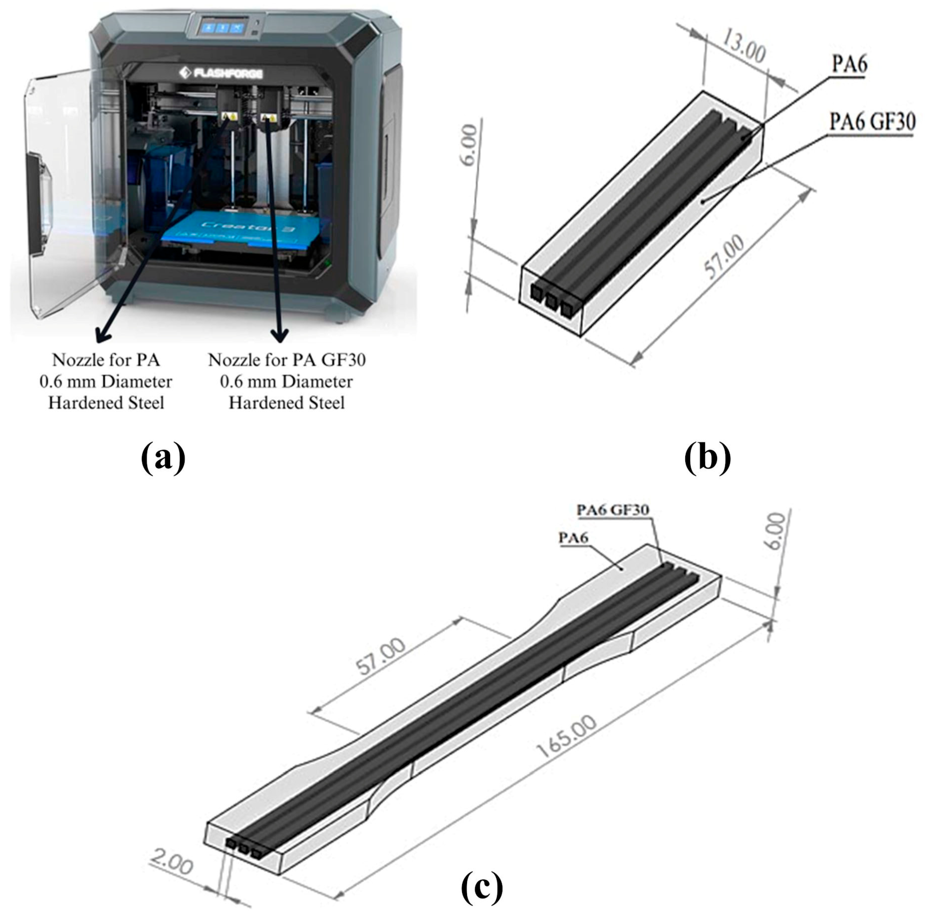
2.1. Materials
2.2. Experimental Design
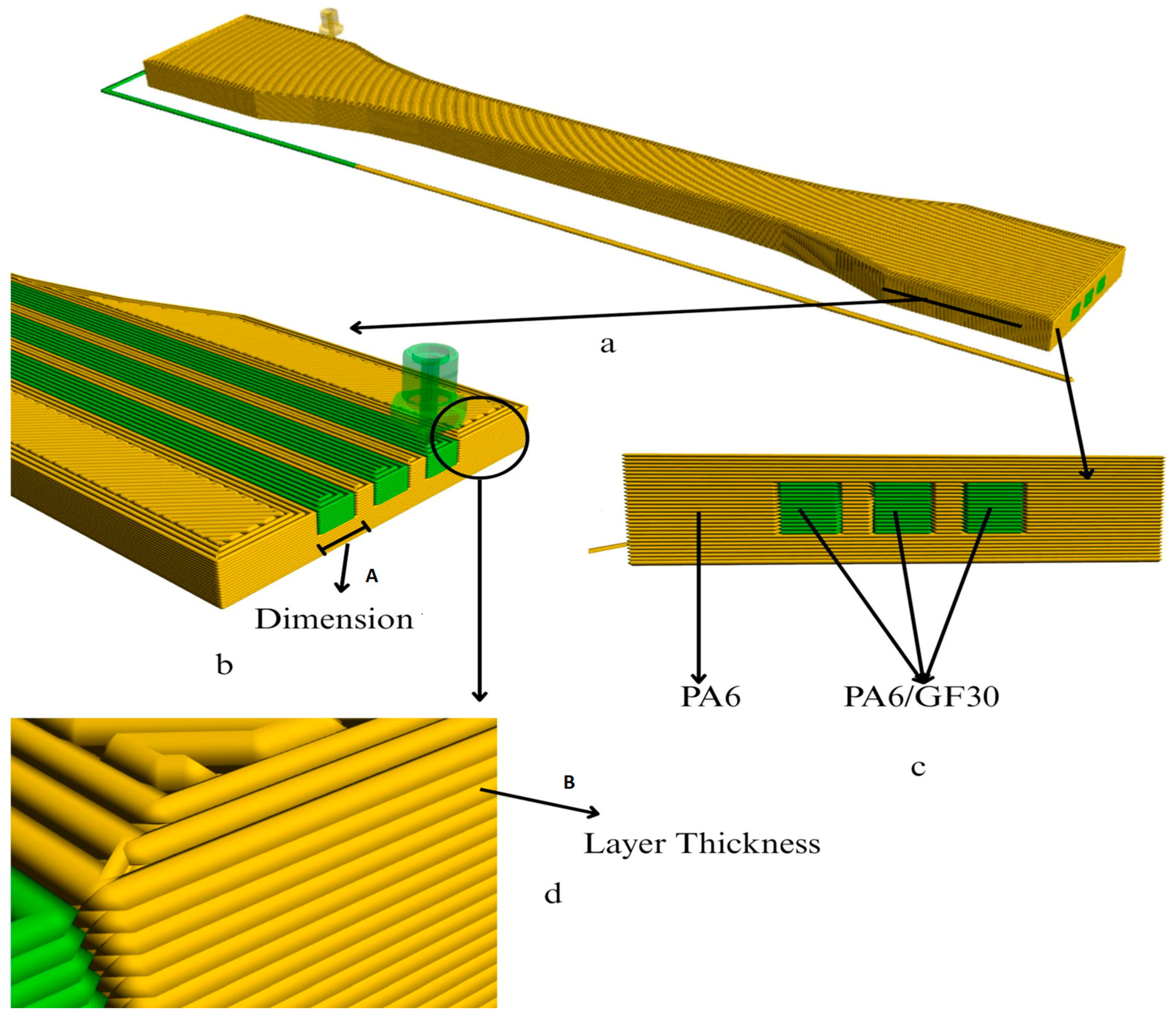
2.3. Design and Production of PA6/PA6GF30 Composites
2.4. Characterization
2.5. Statistical Analysis
3. Results and Discussion
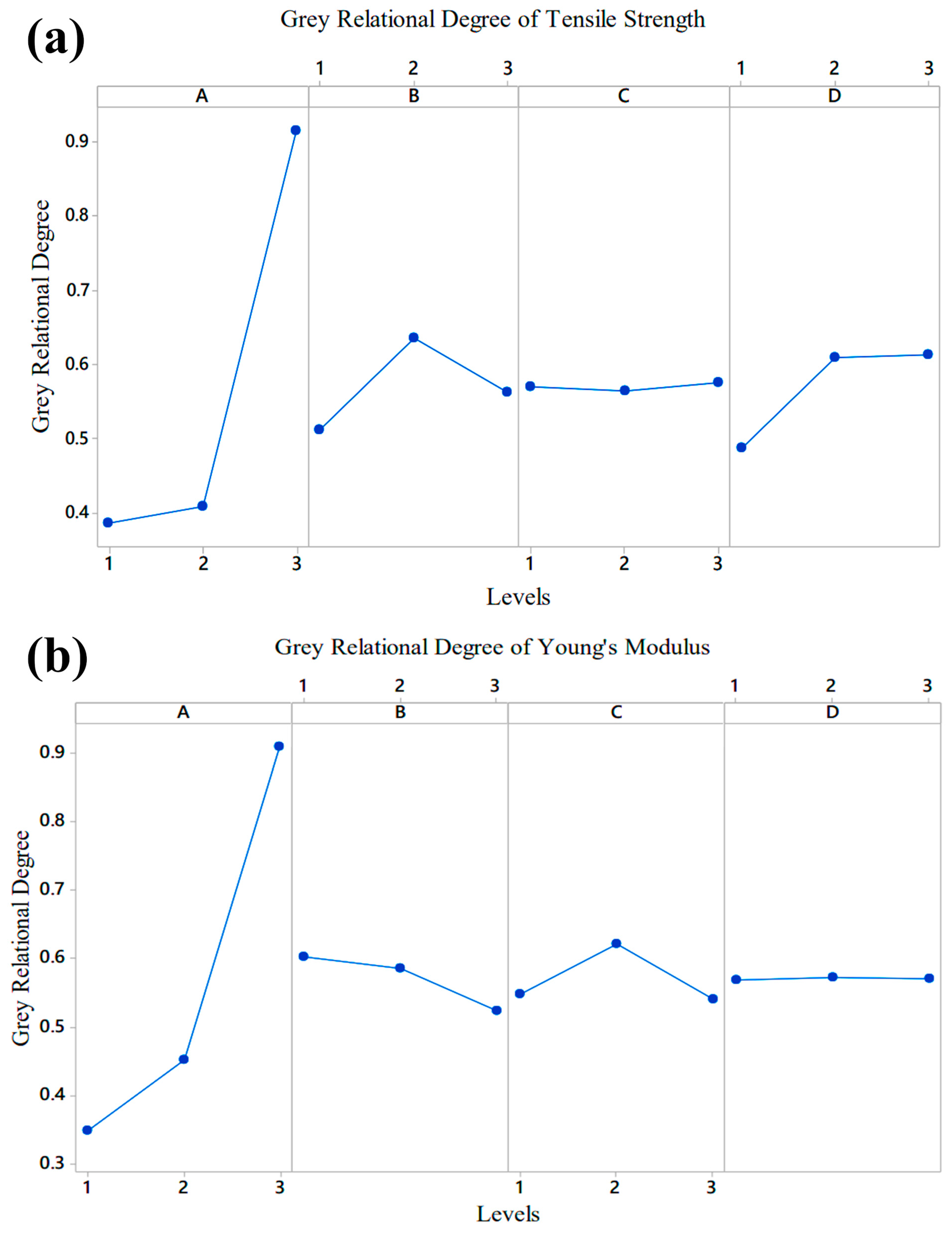
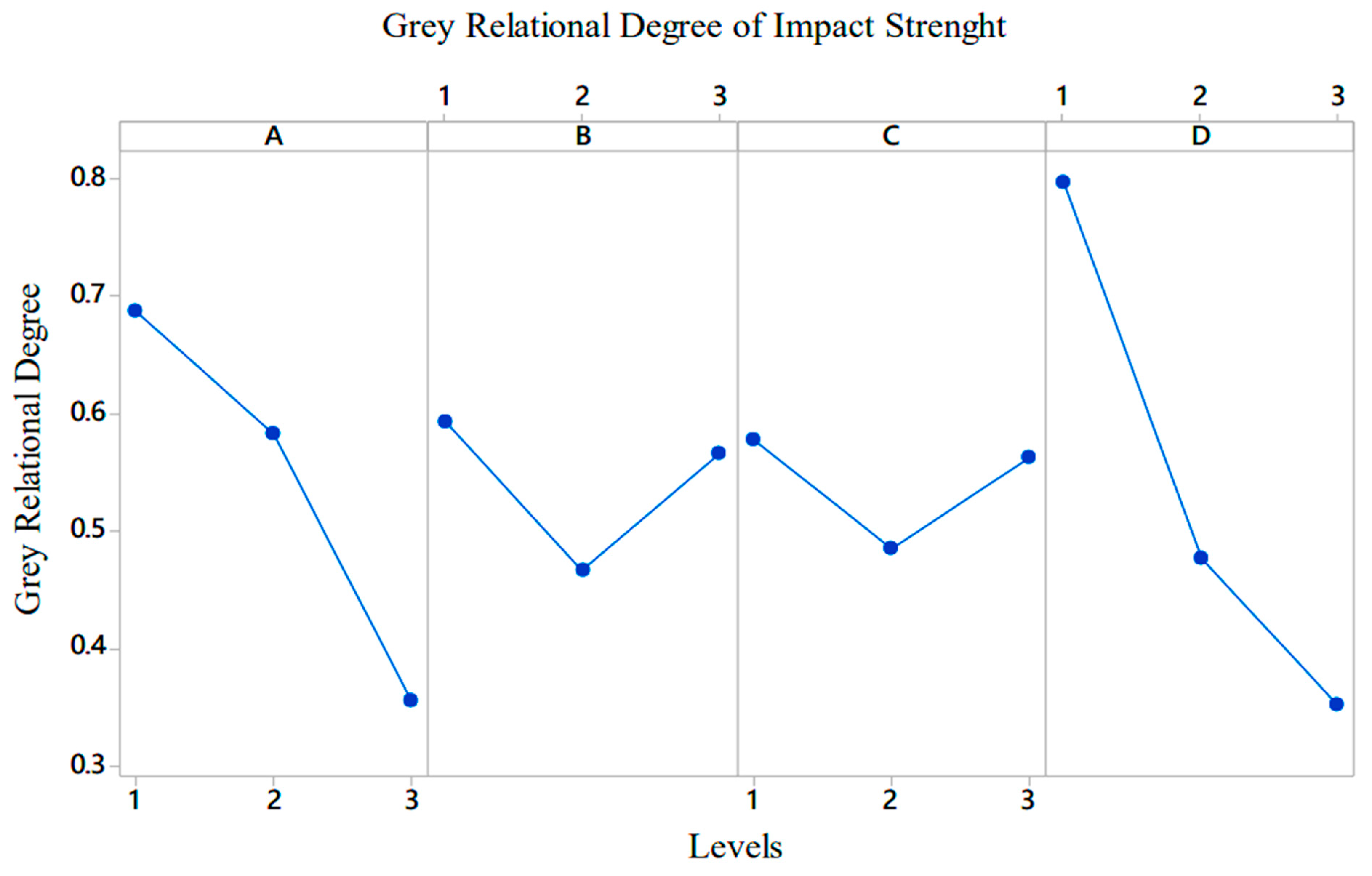
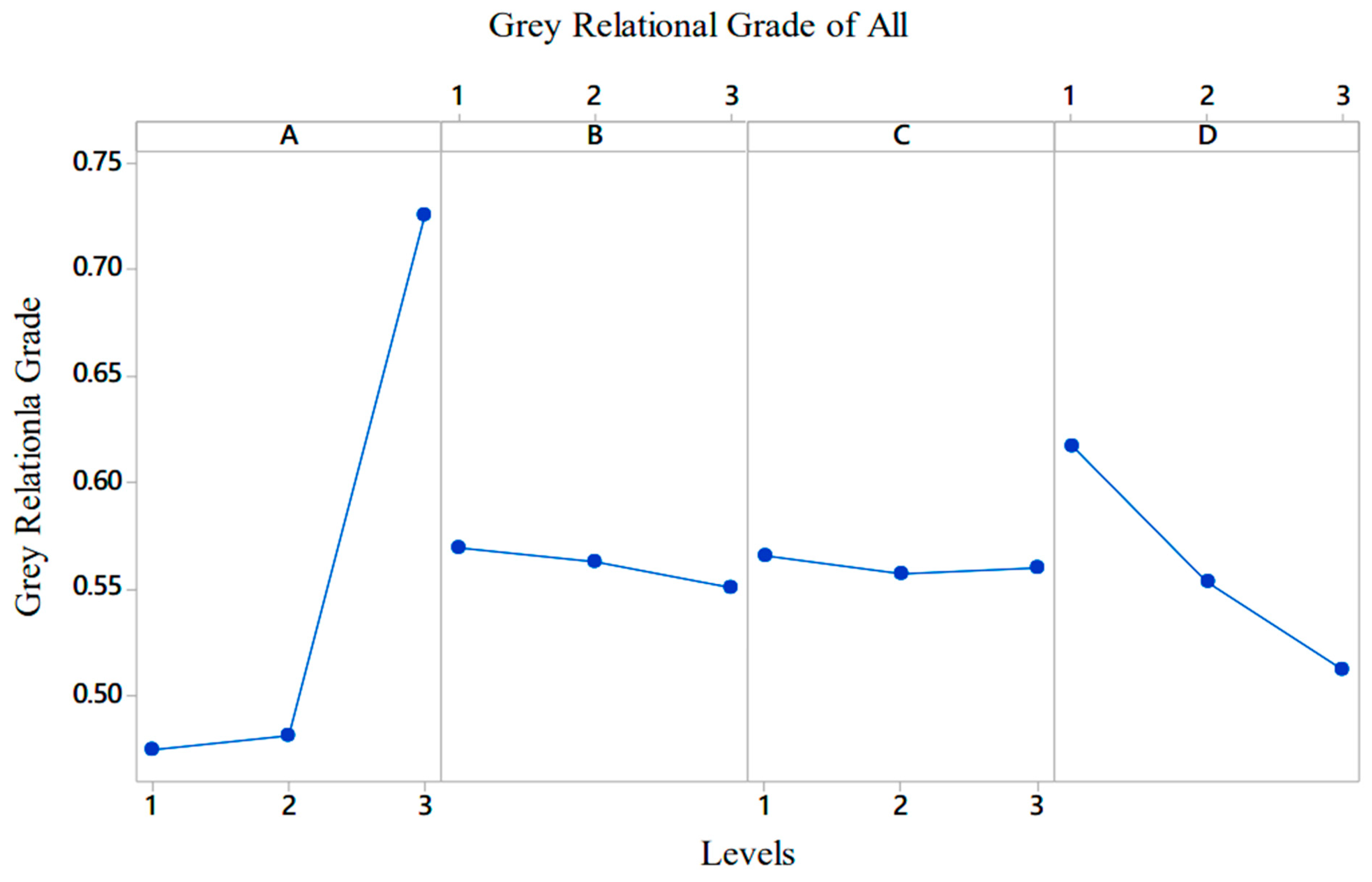
3.1. GRA Analyses of Mechanical Properties
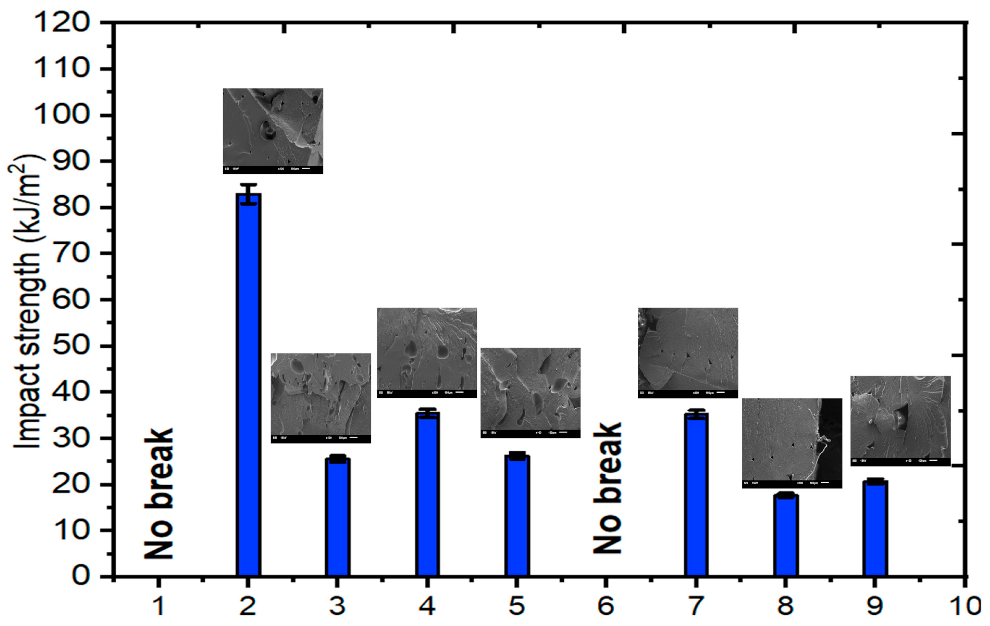
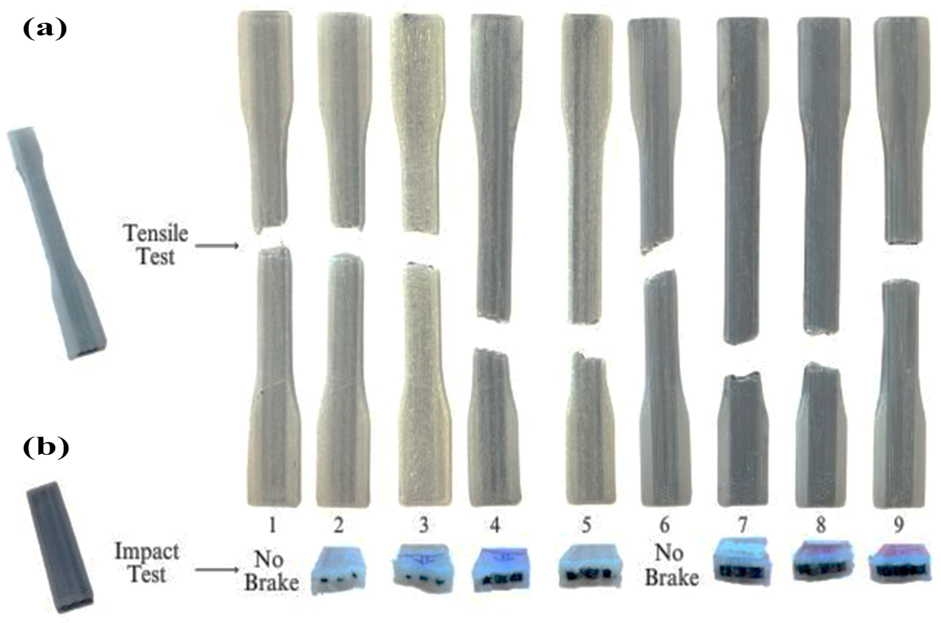
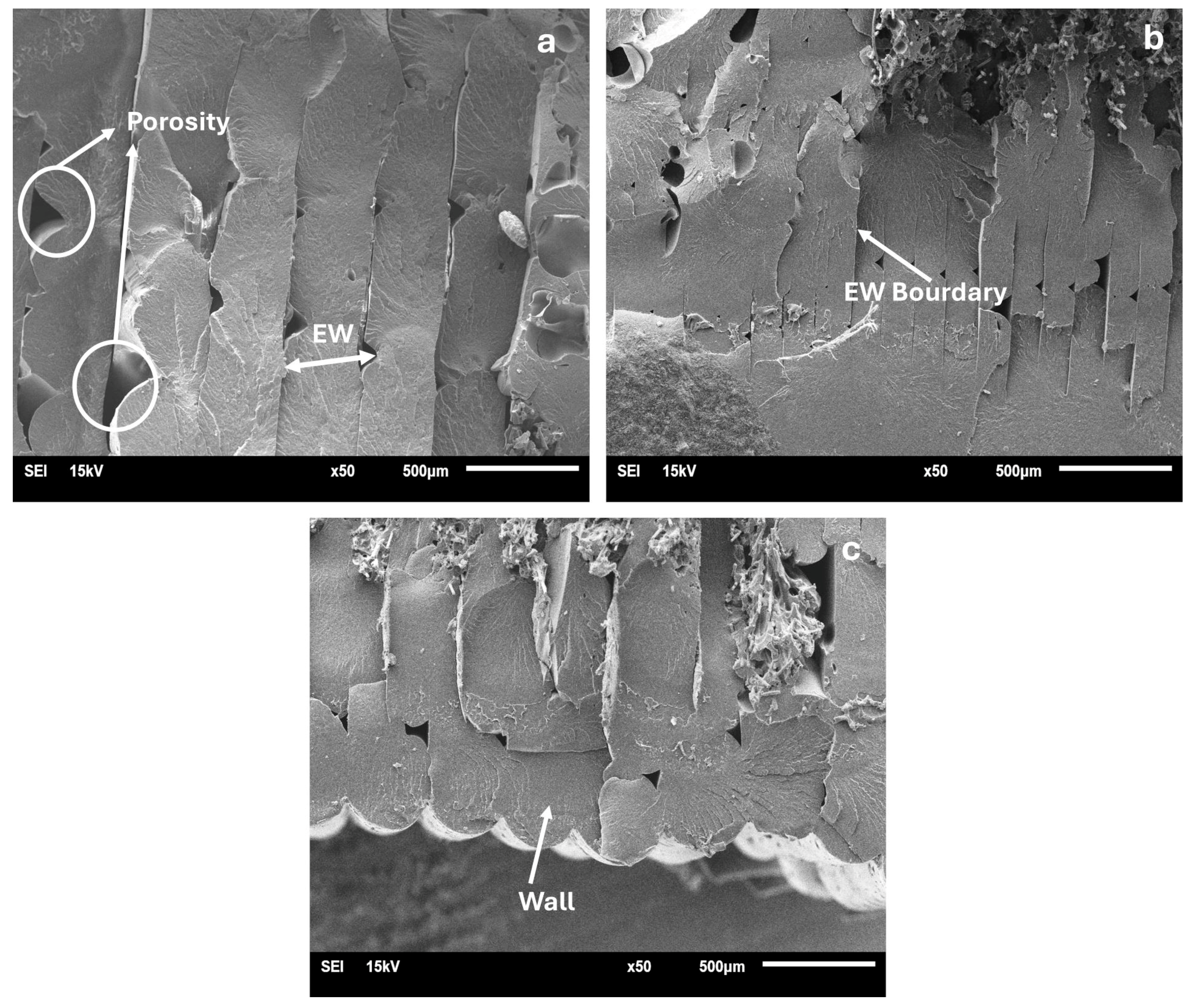
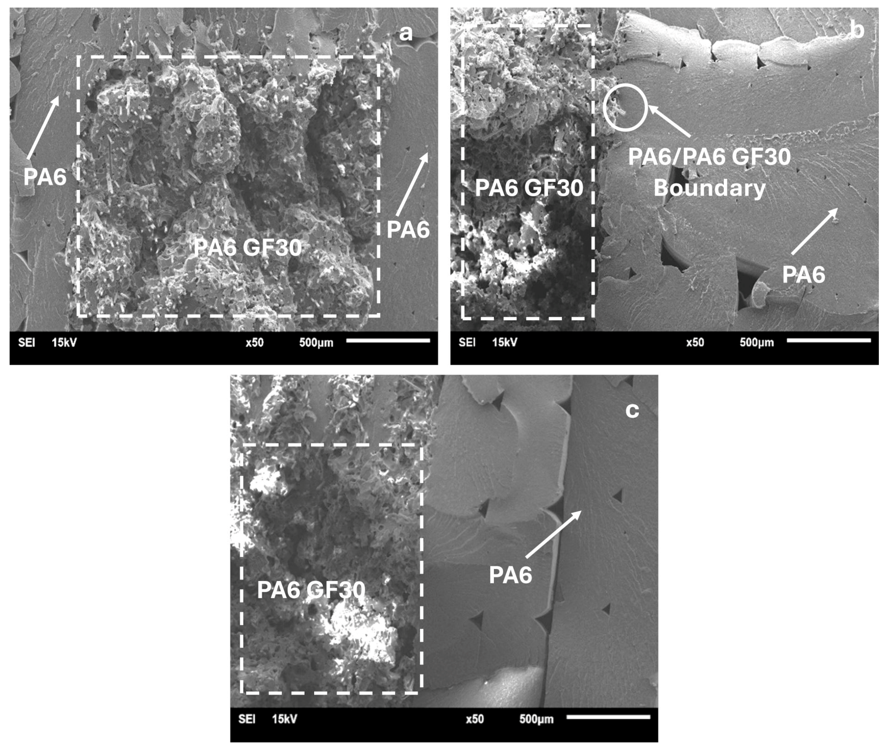
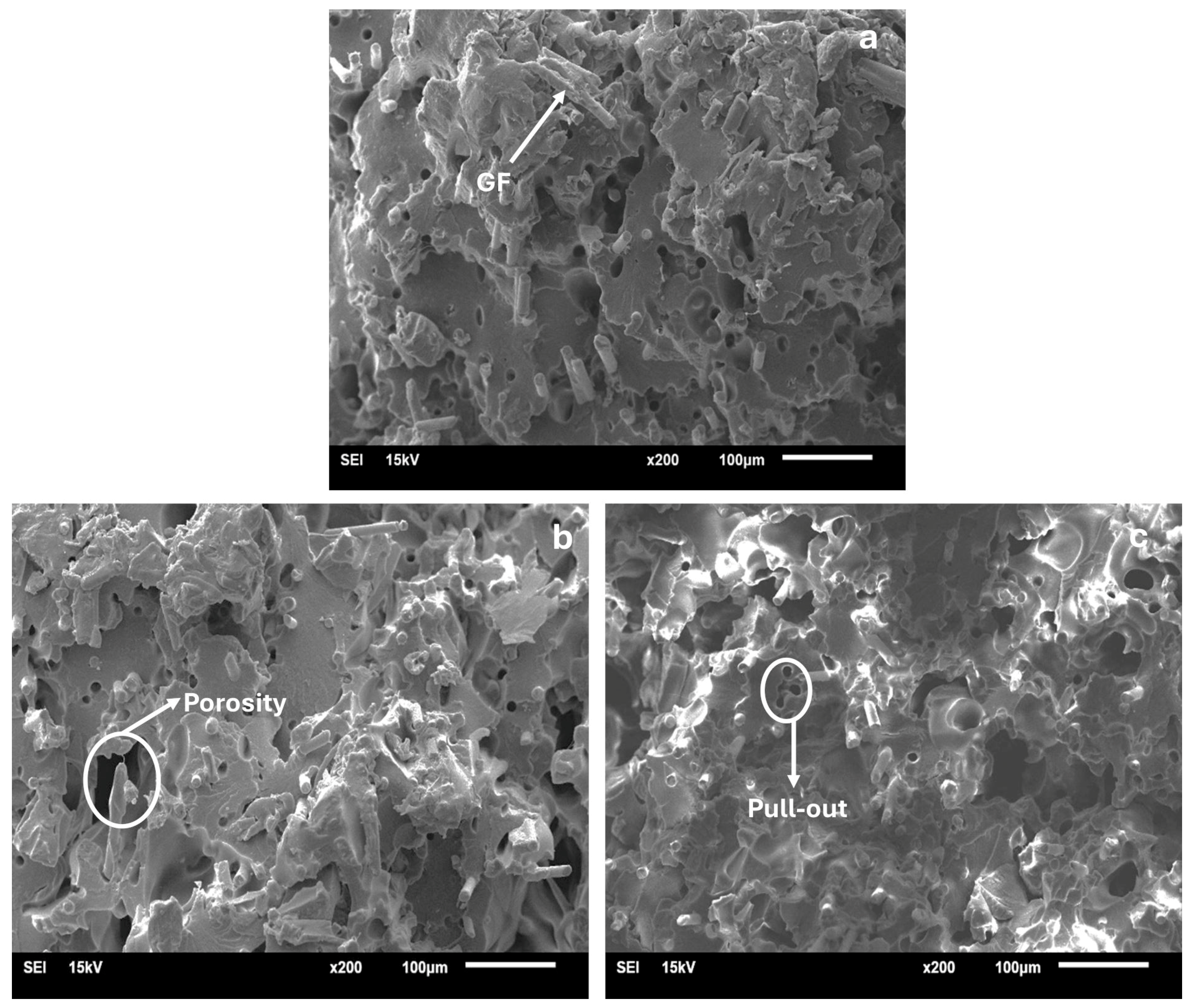
3.2. SEM Analysis Results
4. Conclusions
Author Contributions
Funding
Institutional Review Board Statement
Data Availability Statement
Acknowledgments
Conflicts of Interest
References
- Zhu, S.; Liu, Z.; Li, W.; Zhang, H.; Dai, G.; Zhou, X. Research progress of self-healing polymer materials for flexible electronic devices. J. Polym. Sci. 2023, 61, 1554–1571. [Google Scholar] [CrossRef]
- Raja, S.; Mustafa, M.A.; Ghadir, G.K.; Al-Tmimi, H.M.; Alani, Z.K.; Rusho, M.A.; Rajeswari, N. Unlocking the potential of polymer 3D printed electronics: Challenges and solutions. Appl. Chem. Eng. 2024, 7, 3877. [Google Scholar] [CrossRef]
- Raja, S.; Al-Tmimi, H.M.; Ghadir, G.K.; Mustafa, M.A.; Alani, Z.K.; Rusho, M.A.; Rajeswari, N. An analysis of polymer material selection and design optimization to improve Structural Integrity in 3D printed aerospace components. Appl. Chem. Eng. 2024, 7, 1875. [Google Scholar] [CrossRef]
- Al Menen, B.; Ekinci, A.; Oksuz, M.; Ates, M.; Aydin, I. Effect of processing parameters on the properties of two-component injection molded recycled polypropylene/ethylene propylene diene monomer automotive parts. Int. J. Adv. Manuf. Technol. 2023, 127, 845–860. [Google Scholar] [CrossRef]
- Kouvatsos, T.; Pagonis, D.N.; Iakovidis, I.; Kaltsas, G. Towards a 3D Printed Strain Sensor Employing Additive Manufacturing Technology for the Marine Industry. Appl. Sci. 2024, 14, 6490. [Google Scholar] [CrossRef]
- Yadav, R.; Singh, M.; Shekhawat, D.; Lee, S.Y.; Park, S.J. The role of fillers to enhance the mechanical, thermal, and wear characteristics of polymer composite materials: A review. Compos. Part A Appl. Sci. Manuf. 2023, 175, 107775. [Google Scholar] [CrossRef]
- Berktas, M.E.; Ekinci, A.; Oksuz, M.; Ates, M.; Aydin, I. Influence of nucleating agent on the mechanical and thermal properties of neat isotactic polypropylene/reprocessed polypropylene blends. Iran. Polym. J. 2024, 34, 299–310. [Google Scholar] [CrossRef]
- Gnatowski, A.; Kijo-Kleczkowska, A. Thermomechanical Properties of Polymers and Their Composites with Other Materials: Advances in Thermal and Mechanical Properties of Polymeric Materials. Materials 2024, 17, 494. [Google Scholar] [CrossRef]
- Ekinci, A.; Öksüz, M.; Ates, M.; Aydin, I. Polypropylene/postconsumer recycled poly(ethylene terephthalate) hybrid composites: Evaluation of morphological, mechanical, thermal and electrical properties. Iran. Polym. J. 2022, 31, 1283–1295. [Google Scholar] [CrossRef]
- Arora, N.; Dua, S.; Singh, V.K.; Singh, S.K.; Senthilkumar, T. A Comprehensive Review on Fillers and Mechanical Properties of 3D Printed Polymer Composites. Mater. Today Commun. 2024, 40, 109617. [Google Scholar] [CrossRef]
- Kazim, M.N.A.; Abdollah, M.F.B.; Amiruddin, H.; Liza, S.; Ramli, F.R. Mechanical Properties of Additively Manufactured New Polymer Blend (Polylactic Acid-Polycarbonate Urethane) with Varying Printing Layer Thickness. J. Mater. Eng. Perform. 2024, 33, 4461–4469. [Google Scholar] [CrossRef]
- Cheng, P.; Peng, Y.; Li, S.; Rao, Y.; Le Duigou, A.; Wang, K.; Ahzi, S. 3D printed continuous fiber reinforced composite lightweight structures: A review and outlook. Compos. Part B Eng. 2023, 250, 110450. [Google Scholar] [CrossRef]
- Ekinci, A.; Öksüz, M.; Ates, M.; Aydin, I. Thermal and Mechanical Properties of Polypropylene/Post-consumer Poly(ethylene terephthalate) Blends: Bottle-to-Bottle recycling. J. Polym. Res. 2022, 29, 433. [Google Scholar] [CrossRef]
- Ryu, J.B.; Lyu, M.Y. A study on the mechanical property and 3D fiber distribution in injection molded glass fiber reinforced PA66. Int. Polym. Process. 2014, 29, 389–401. [Google Scholar] [CrossRef]
- Chen, K.; Jia, M.; Sun, H.; Xue, P. Thermoplastic reaction injection pultrusion for continuous glass fiber-reinforced polyamide-6 composites. Materials 2019, 12, 463. [Google Scholar] [CrossRef] [PubMed]
- Vidakis, N.; Petousis, M.; Tzounis, L.; Maniadi, A.; Velidakis, E.; Mountakis, N.; Kechagias, J.D. Sustainable additive manufacturing: Mechanical response of polyamide 12 over multiple recycling processes. Materials 2021, 14, 466. [Google Scholar] [CrossRef]
- Das, A.; Etemadi, M.; Davis, B.A.; McKnight, S.H.; Williams, C.B.; Case, S.W.; Bortner, M.J. Rheological investigation of nylon-carbon fiber composites fabricated using material extrusion-based additive manufacturing. Polym. Compos. 2021, 42, 6010–6024. [Google Scholar] [CrossRef]
- Dizon, J.R.C.; Espera, A.H., Jr.; Chen, Q.; Advincula, R.C. Mechanical characterization of 3D-printed polymers. Addit. Manuf. 2018, 20, 44–67. [Google Scholar] [CrossRef]
- Wang, X.; Jiang, M.; Zhou, Z.; Gou, J.; Hui, D. 3D printing of polymer matrix composites: A review and prospective. Compos. Part B Eng. 2017, 110, 442–458. [Google Scholar] [CrossRef]
- Al Rashid, A.; Ikram, H.; Koç, M. Additive manufacturing and mechanical performance of carbon fiber reinforced Polyamide-6 composites. Mater. Today Proc. 2022, 62, 6359–6363. [Google Scholar] [CrossRef]
- Al Rashid, A.; Khan, S.A.; Al-Ghamdi, S.G.; Koç, M. Additive manufacturing: Technology, applications, markets, and opportunities for the built environment. Autom. Constr. 2020, 118, 103268. [Google Scholar] [CrossRef]
- Al-Mazrouei, N.; Al-Marzouqi, A.H.; Ahmed, W. Characterization and sustainability potential of recycling 3D-printed nylon composite wastes. Sustainability 2022, 14, 10458. [Google Scholar] [CrossRef]
- Bolat, Ç.; Ergene, B. Wear performance of short fiber added polyamide composites produced by additive manufacturing: Combined impacts of secondary heat treatment, reinforcement type, and test force. Polym. Compos. 2024, 45, 6885–6900. [Google Scholar] [CrossRef]
- Zhang, J.; Dong, W.; Li, X.; Wei, Y.; Hu, Z.; Shiju, E.; Zheng, J.; Chen, H.; Wang, S. Optimal short carbon fiber-reinforced polyamide 6 composites with lifted high strength and toughness for fused filament fabrication. Polym. Compos. 2024, 45, 14580–14594. [Google Scholar] [CrossRef]
- Tóth, C.; Lukács, N.L.; Kovács, N.K. The role of the fiber–matrix interface in the tensile properties of short fiber–reinforced 3D-printed polylactic acid composites. Polym. Compos. 2024, 45, 13589–13602. [Google Scholar] [CrossRef]
- Chen, Y.; Wei, X.; Mao, J.; Zhao, M.; Liu, G. Experimental analysis of 3D printed continuous carbon/glass hybrid fiber reinforced PLA composites: Revealing synergistic mechanical properties and failure mechanisms. Polym. Compos. 2024, 45, 10888–10897. [Google Scholar] [CrossRef]
- Iacob, D.V.; Zisopol, D.G.; Minescu, M. Technical-Economical Study on the Optimization of FDM Parameters for the Manufacture of PETG and ASA Parts. Polymers 2024, 16, 2260. [Google Scholar] [CrossRef] [PubMed]
- Galațanu, S.V.; Serralha, F.N.; Mărghitaș, M.P.; Șoșdean, C.; Popa, C.F.; Emanoil, L.; Marșavina, L. Mechanical behavior of recycled FDM printed parts from PETG in the circular economy. Procedia Struct. Integr. 2024, 56, 138–143. [Google Scholar] [CrossRef]
- Rodríguez-Reyna, S.L.; Mata, C.; Díaz-Aguilera, J.H.; Acevedo-Parra, H.R.; Tapia, F. Mechanical properties optimization for PLA, ABS and Nylon+ CF manufactured by 3D FDM printing. Mater. Today Commun. 2022, 33, 104774. [Google Scholar] [CrossRef]
- Kumar, S.; Singh, R.; Singh, M.; Singh, T.P.; Batish, A. Multi material 3D printing of PLA-PA6/TiO2 polymeric matrix: Flexural, wear and morphological properties. J. Thermoplast. Compos. Mater. 2022, 35, 2105–2124. [Google Scholar] [CrossRef]
- Soundararajan, R.; Jayasuriya, N.; Vishnu, R.G.; Prassad, B.G.; Pradeep, C. Appraisal of mechanical and tribological properties on PA6-TiO2 composites through fused deposition modelling. Mater. Today Proc. 2019, 18, 2394–2402. [Google Scholar] [CrossRef]
- Beyaz, R.; Ekinci, A.; Yurtbasi, Z.; Oksuz, M.; Ates, M.; Aydin, I. Thermal, electrical and mechanical properties of carbon fiber/copper powder/carbon black reinforced hybrid Polyamide 6,6 composites. High Perform. Polym. 2023, 35, 103–114. [Google Scholar] [CrossRef]
- Bochnia, J.; Blasiak, M.; Kozior, T. Tensile strength analysis of thin-walled polymer glass fiber reinforced samples manufactured by 3D printing technology. Polymers 2020, 12, 2783. [Google Scholar] [CrossRef] [PubMed]
- Ahmadifar, M.; Benfriha, K.; Shirinbayan, M. Thermal, tensile and fatigue behaviors of the PA6, short carbon fiber-reinforced PA6, and continuous glass fiber-reinforced PA6 materials in fused filament fabrication (FFF). Polymers 2023, 15, 507. [Google Scholar] [CrossRef] [PubMed]
- Peng, X.; Zhang, M.; Guo, Z.; Sang, L.; Hou, W. Investigation of processing parameters on tensile performance for FDM-printed carbon fiber reinforced polyamide 6 composites. Compos. Commun. 2020, 22, 100478. [Google Scholar] [CrossRef]
- Touchard, F.; Chocinski-Arnault, L.; Fournier, T.; Magro, C.; Lafitte, A.; Caradec, A. Interfacial adhesion quality in 3D printed continuous CF/PA6 composites at filament/matrix and interlaminar scales. Compos. Part B Eng. 2021, 218, 108891. [Google Scholar] [CrossRef]
- Sun, B.; Mubarak, S.; Zhang, G.; Peng, K.; Hu, X.; Zhang, Q.; Wu, L.; Wang, J. Fused-Deposition Modeling 3D Printing of Short-Cut Carbon-Fiber-Reinforced PA6 Composites for Strengthening, Toughening, and Light Weighting. Polymers 2023, 15, 3722. [Google Scholar] [CrossRef]
- De Toro, E.V.; Sobrino, J.C.; Martínez, A.M.; Eguía, V.M.; Pérez, J.A. Investigation of a short carbon fibre-reinforced polyamide and comparison of two manufacturing processes: Fused Deposition Modelling (FDM) and polymer injection moulding (PIM). Materials 2020, 13, 672. [Google Scholar] [CrossRef]
- Morales, U.; Esnaola, A.; Iragi, M.; Aretxabaleta, L.; Aurrekoetxea, J. Quasi-static and dynamic crush behaviour of 3D printed thin-walled profiles reinforced with continuous carbon and glass fibres. Compos. Part B Eng. 2021, 217, 108865. [Google Scholar] [CrossRef]
- Beylergil, B.; Al-Nadhari, A.; Yildiz, M. Optimization of Charpy-impact strength of 3D-printed carbon fiber/polyamide composites by Taguchi method. Polym. Compos. 2023, 44, 2846–2859. [Google Scholar] [CrossRef]
- Al Rashid, A.; Koç, M. Numerical simulations on thermomechanical performance of 3D printed chopped carbon fiber-reinforced polyamide-6 composites: Effect of infill design. J. Appl. Polym. Sci. 2022, 139, e53081. [Google Scholar] [CrossRef]
- Shashikumar, S.; Sreekanth, M.S. Investigation on mechanical properties of polyamide 6 and carbon fiber reinforced composite manufactured by fused deposition modeling technique. J. Thermoplast. Compos. Mater. 2024, 37, 1730–1747. [Google Scholar] [CrossRef]
- He, Q.; Wang, H.; Fu, K.; Ye, L. 3D printed continuous CF/PA6 composites: Effect of microscopic voids on mechanical performance. Compos. Sci. Technol. 2020, 191, 108077. [Google Scholar] [CrossRef]
- Su, N.; Pierce, R.S.; Rudd, C.; Liu, X. Comprehensive investigation of reclaimed carbon fibre reinforced polyamide (rCF/PA) filaments and FDM printed composites. Compos. Part B Eng. 2022, 233, 109646. [Google Scholar] [CrossRef]
- Hadi, A.; Kadauw, A.; Zeidler, H. The effect of printing temperature and moisture on tensile properties of 3D printed glass fiber reinforced nylon 6. Mater. Today Proc. 2023, 91, 48–55. [Google Scholar] [CrossRef]
- Ramezani Dana, H.; El Mansori, M.; Barrat, M.; Seck, C.A. Tensile behavior of additively manufactured carbon fiber reinforced polyamide-6 composites. Polym.-Plast. Technol. Mater. 2022, 61, 624–641. [Google Scholar] [CrossRef]
- Sugiyama, K.; Matsuzaki, R.; Ueda, M.; Todoroki, A.; Hirano, Y. 3D printing of composite sandwich structures using continuous carbon fiber and fiber tension. Compos. Part A Appl. Sci. Manuf. 2018, 113, 114–121. [Google Scholar] [CrossRef]
- Xu, W.; Yu, L.; Chen, K.; Zhang, R.; Xue, P.; Jia, M. Dual nozzle 3D printing strategy to improve the surface quality of continuous glass fiber reinforced polyamide 6 composites. J. Appl. Polym. Sci. 2023, 140, e54276. [Google Scholar] [CrossRef]
- Guan, S.; Wang, F.; Wang, H.; Wang, G.; Lei, Y.; Fu, R.; Jia, Z. Enhancing planar compression performance of 3D printed continuous carbon fiber reinforced honeycomb sandwich structures using interleaved core paths. J. Manuf. Process. 2024, 120, 940–950. [Google Scholar] [CrossRef]
- El Essawi, B.; Abdallah, S.; Ali, S.; Mohammed, A.N.A.; Susantyoko, R.A.; Pervaiz, S. Optimization of infill density, fiber angle, carbon fiber layer position in 3D printed continuous carbon-fiber reinforced nylon composite. Results Eng. 2024, 21, 101926. [Google Scholar] [CrossRef]
- Hartomacioglu, S.; Kaya, E.; Eker, B.; Daglı, S.; Sarıkaya, M. Characterization, generative design, and fabrication of a carbon fiber-reinforced industrial robot gripper via additive manufacturing. J. Mater. Res. Technol. 2024, 33, 3714–3727. [Google Scholar] [CrossRef]
- Hsueh, M.H.; Lai, C.J.; Wang, S.H.; Zeng, Y.S.; Hsieh, C.H.; Pan, C.Y.; Huang, W.C. Effect of Printing Parameters on the Thermal and Mechanical Properties of 3D-Printed PLA and PETG, Using Fused Deposition Modeling. Polymers 2021, 13, 1758. [Google Scholar] [CrossRef] [PubMed]
- Rivera-López, F.; Pavón, M.M.L.; Correa, E.C.; Molina, M.H. Effects of Nozzle Temperature on Mechanical Properties of Polylactic Acid Specimens Fabricated by Fused Deposition Modeling. Polymers 2024, 16, 1867. [Google Scholar] [CrossRef] [PubMed]
- Zhang, Z.; Chang, L. Effects of Absorption on the Tribological Properties of Carbon Fiber Reinforced Polyamide-6 Composites Manufactured by Fused Deposition Modeling. J. Tribol. 2025, 147, 041404. [Google Scholar] [CrossRef]
- Yilmaz, S. Comprehensive analysis of 3D printed PA6. 6 and fiber-reinforced variants: Revealing mechanical properties and adhesive wear behavior. Polym. Compos. 2024, 45, 1446–1460. [Google Scholar] [CrossRef]

| Material Properties | Unit | PA6 | PA6GF30 |
|---|---|---|---|
| Density | kg/m3 | 1115 | 1356 |
| Glass transition temperature | °C | 49 | 67 |
| Melting temperature | °C | 197 | 209 |
| Tensile strength | MPa | 61.40 | 78.30 |
| Elongation at break | % | 9.60 | 2.20 |
| Young’s modulus | MPa | 2419 | 5036 |
| Impact strength Izod, notched | kJ/m2 | 5.80 | 9.20 |
| Impact strength Izod, unnotched | kJ/m2 | 28 | 38.40 |
| Sample Number | Parameters | |||
|---|---|---|---|---|
| (A) | (B) | (C) | (D) | |
| Dimension of Geometric Shape (mm) | Layer Thickness (mm) | Nozzle Temperature (°C) | Post-Heat Treatment Time (min.) | |
| 1 | 1.20 | 0.15 | 260 | 0 |
| 2 | 1.20 | 0.25 | 270 | 60 |
| 3 | 1.20 | 0.35 | 280 | 120 |
| 4 | 2.00 | 0.15 | 260 | 60 |
| 5 | 2.00 | 0.25 | 270 | 120 |
| 6 | 2.00 | 0.35 | 280 | 0 |
| 7 | 2.80 | 0.15 | 270 | 0 |
| 8 | 2.80 | 0.25 | 280 | 60 |
| 9 | 2.80 | 0.35 | 260 | 120 |
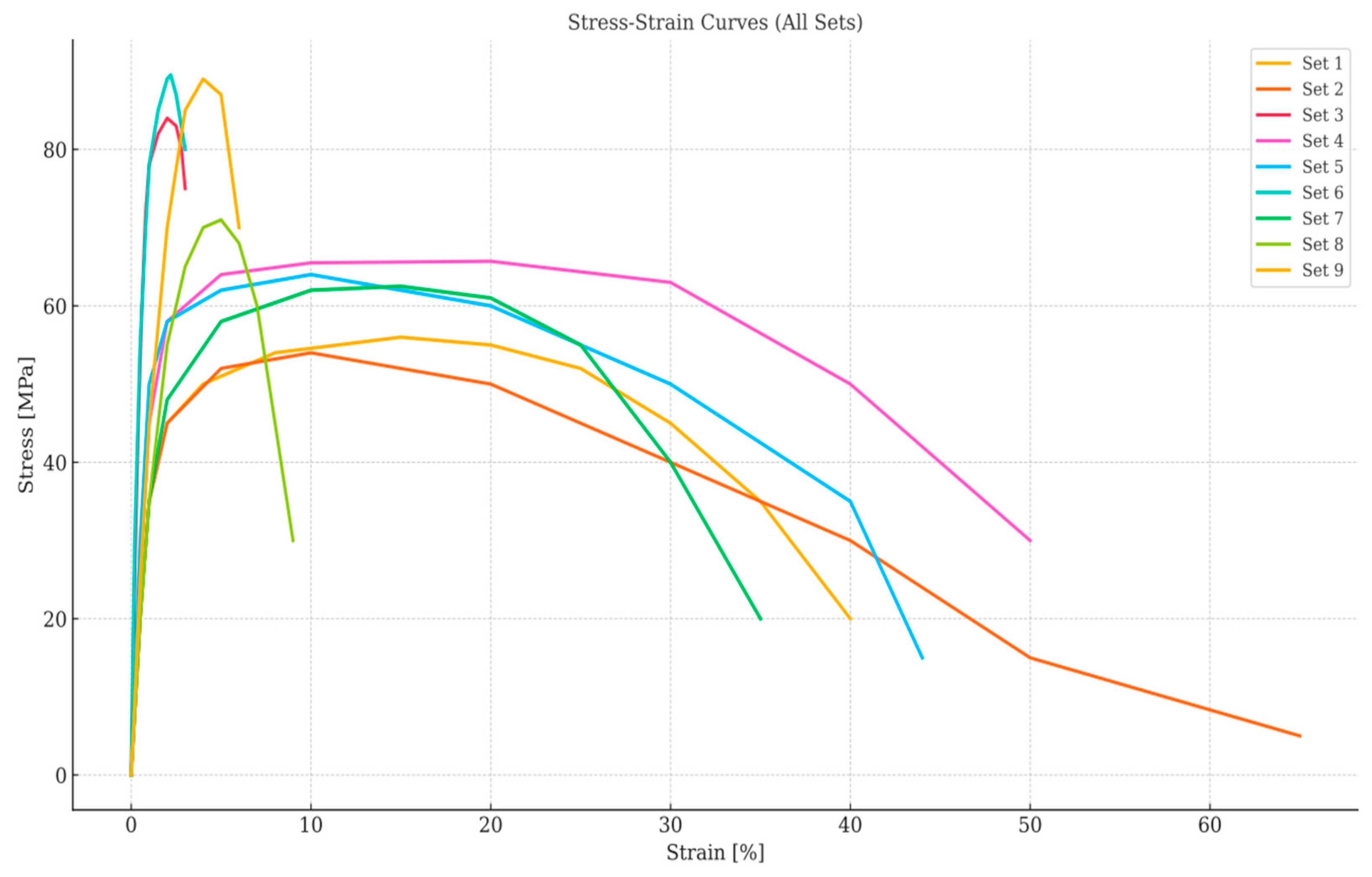
| Sample Number | Impact Strength (kJ/m2) | Tensile Strength (MPa) | Young’s Modulus (MPa) |
|---|---|---|---|
| 1 | No break | 55.88 ± 8.60 | 1663 ± 531 |
| 2 | 83.00 | 65.61 ± 0.26 | 1995 ± 63 |
| 3 | 25.63 | 62.48 ± 3.95 | 2035 ± 196 |
| 4 | 35.46 | 64.13 ± 4.29 | 3177 ± 130 |
| 5 | 26.28 | 71.09 ± 1.66 | 3445 ± 150 |
| 6 | No break | 54.42 ± 3.06 | 2206 ± 170 |
| 7 | 35.27 | 84.98 ± 4.36 | 5082 ± 113 |
| 8 | 17.75 | 89.89 ± 3.70 | 4866 ± 213 |
| 9 | 20.73 | 89.11 ± 1.47 | 4759 ± 202 |
| Sample Number | Impact Strength | Tensile Strength | Young’s Modulus |
|---|---|---|---|
| 1 | 1.0000 | 0.0412 | 0.0000 |
| 2 | 0.7933 | 0.3155 | 0.0971 |
| 3 | 0.0958 | 0.2272 | 0.1088 |
| 4 | 0.2153 | 0.2738 | 0.4428 |
| 5 | 0.1037 | 0.4700 | 0.5212 |
| 6 | 1.0000 | 0.0000 | 0.1588 |
| 7 | 0.2130 | 0.8616 | 1.0000 |
| 8 | 0.0000 | 1.0000 | 0.9368 |
| 9 | 0.0362 | 0.9780 | 0.9055 |
| Sample Number | Impact Strength | Tensile Strength | Young’s Modulus |
|---|---|---|---|
| 1 | 0.0000 | 0.9588 | 1.0000 |
| 2 | 0.2067 | 0.6845 | 0.9029 |
| 3 | 0.9042 | 0.7728 | 0.8912 |
| 4 | 0.7847 | 0.7262 | 0.5572 |
| 5 | 0.8963 | 0.5300 | 0.4788 |
| 6 | 0.0000 | 1.0000 | 0.8412 |
| 7 | 0.7870 | 0.1384 | 0.0000 |
| 8 | 1.0000 | 0.0000 | 0.0632 |
| 9 | 0.9638 | 0.0220 | 0.0945 |
| Grey Relational Degree | Results | |||
|---|---|---|---|---|
| Impact Strength | Tensile Strength | Young’s Modulus | Grey Relational Grade | Ranking |
| 1.0000 | 0.3427 | 0.3333 | 0.5587 | 5 |
| 0.7075 | 0.4221 | 0.3564 | 0.4953 | 6 |
| 0.3561 | 0.3928 | 0.3594 | 0.3694 | 9 |
| 0.3892 | 0.4077 | 0.4730 | 0.4233 | 8 |
| 0.3581 | 0.4854 | 0.5108 | 0.4514 | 7 |
| 1.0000 | 0.3333 | 0.3728 | 0.5687 | 4 |
| 0.3885 | 0.7832 | 1.0000 | 0.7239 | 2 |
| 0.3333 | 1.0000 | 0.8878 | 0.7404 | 1 |
| 0.3416 | 0.9579 | 0.8411 | 0.7135 | 3 |
Disclaimer/Publisher’s Note: The statements, opinions and data contained in all publications are solely those of the individual author(s) and contributor(s) and not of MDPI and/or the editor(s). MDPI and/or the editor(s) disclaim responsibility for any injury to people or property resulting from any ideas, methods, instructions or products referred to in the content. |
© 2025 by the authors. Licensee MDPI, Basel, Switzerland. This article is an open access article distributed under the terms and conditions of the Creative Commons Attribution (CC BY) license (https://creativecommons.org/licenses/by/4.0/).
Share and Cite
Hartomacıoğlu, S.; Oksuz, M.; Ekinci, A.; Ates, M. Optimization of Produced Parameters for PA6/PA6GF30 Composite Produced by 3D Printing with Novel Knitting Method. Polymers 2025, 17, 1590. https://doi.org/10.3390/polym17121590
Hartomacıoğlu S, Oksuz M, Ekinci A, Ates M. Optimization of Produced Parameters for PA6/PA6GF30 Composite Produced by 3D Printing with Novel Knitting Method. Polymers. 2025; 17(12):1590. https://doi.org/10.3390/polym17121590
Chicago/Turabian StyleHartomacıoğlu, Selim, Mustafa Oksuz, Aysun Ekinci, and Murat Ates. 2025. "Optimization of Produced Parameters for PA6/PA6GF30 Composite Produced by 3D Printing with Novel Knitting Method" Polymers 17, no. 12: 1590. https://doi.org/10.3390/polym17121590
APA StyleHartomacıoğlu, S., Oksuz, M., Ekinci, A., & Ates, M. (2025). Optimization of Produced Parameters for PA6/PA6GF30 Composite Produced by 3D Printing with Novel Knitting Method. Polymers, 17(12), 1590. https://doi.org/10.3390/polym17121590