Determination of Interface Fracture Parameters in Thermoplastic Fiber Metal Laminates Under Mixed-Mode I+II
Abstract
:1. Introduction
2. Experimental Program
- Assessment of constituents (mechanical properties of metal and composite components)
- Assessment of fracture behavior of metal–composite interface in manufactured fiber metal laminate (DCB, ENF, MMB)
- Assessment of fracture behavior in test with variable mixicity-mode (3PB) for validation of the obtained material model
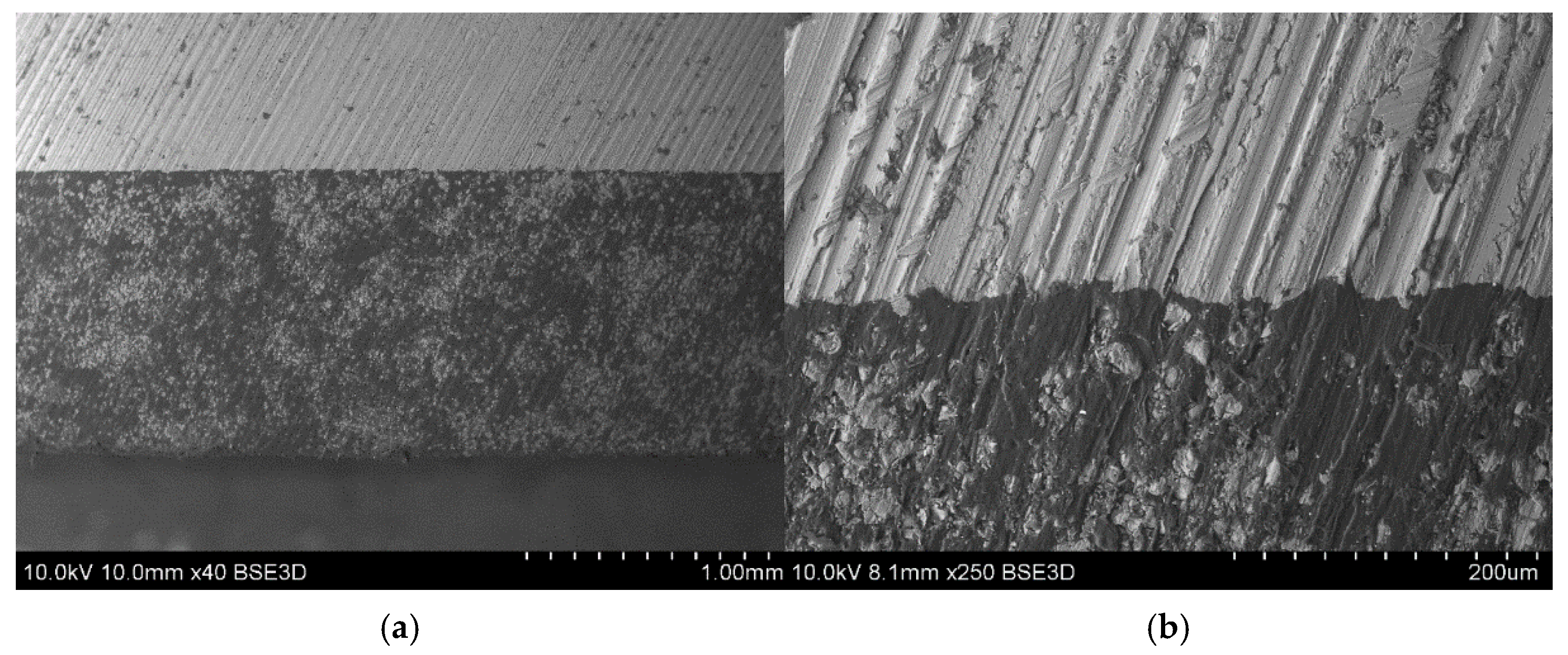
2.1. Material and Manufacturing
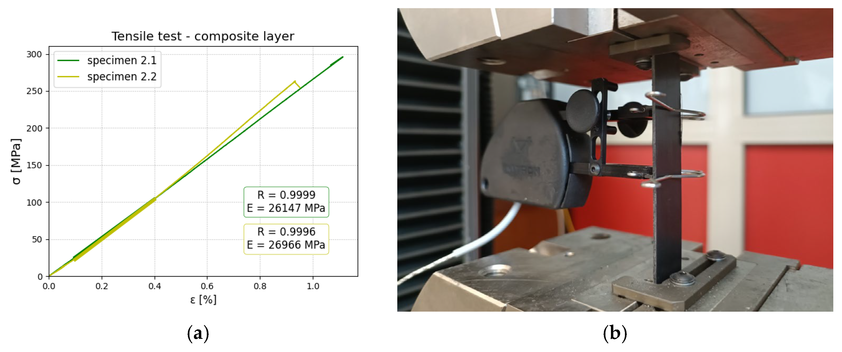
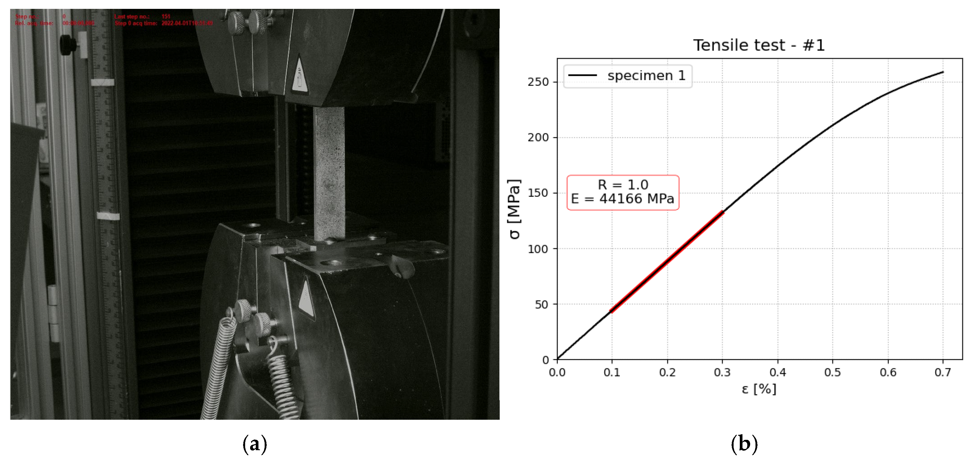
2.2. Tensile Test—Material and Constituent Assessment
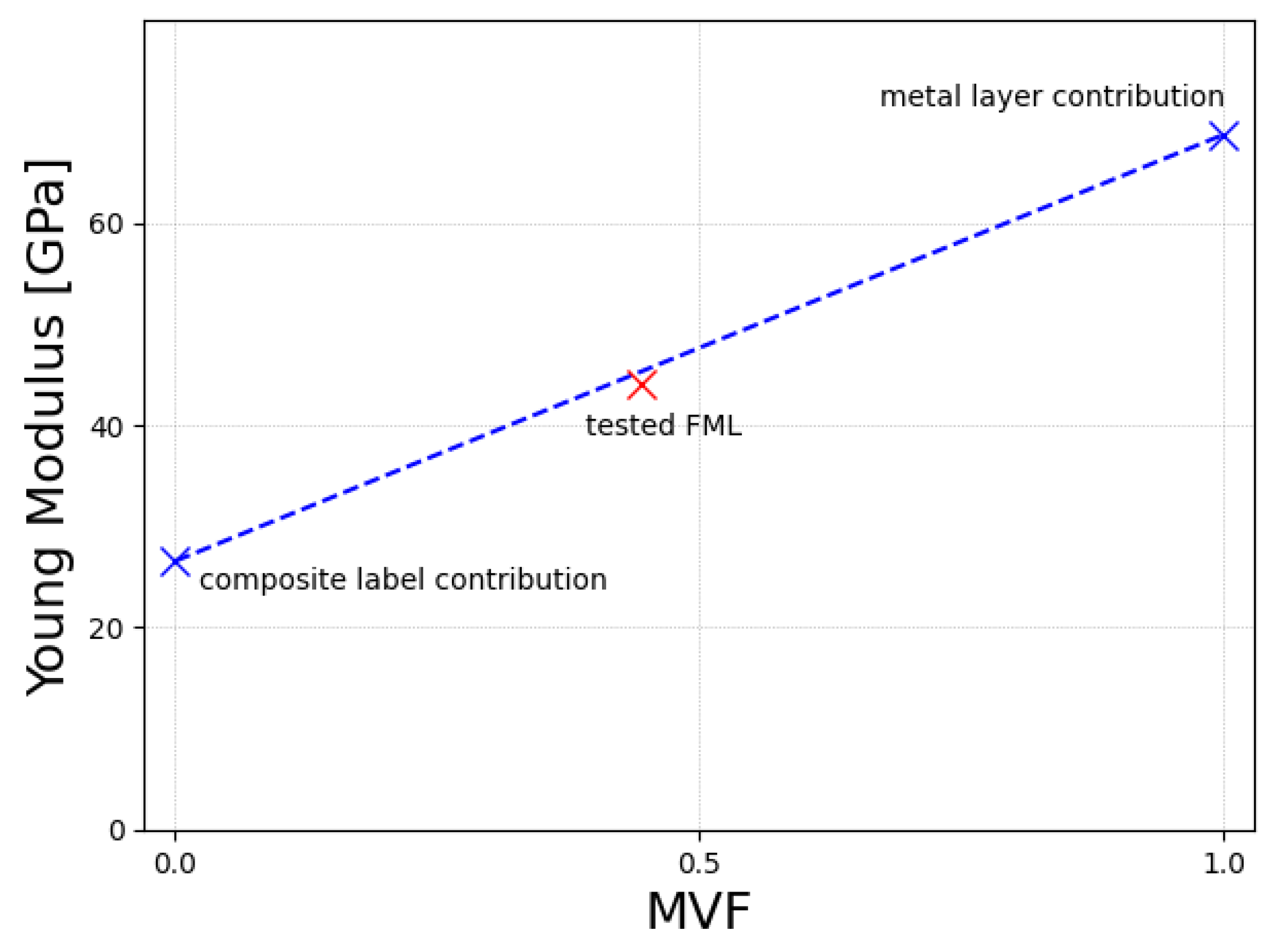
- Aluminium: E = 68,713.4 ± 4311 MPa
- Composite layer-only fibers parallel to the length of the specimen E1 = 26,556 ± 579 MPa, E2 = 4846.5 ± 12 MPa
2.3. Experimental Campaign—DCB, ENF, MMB and 3PB Tests
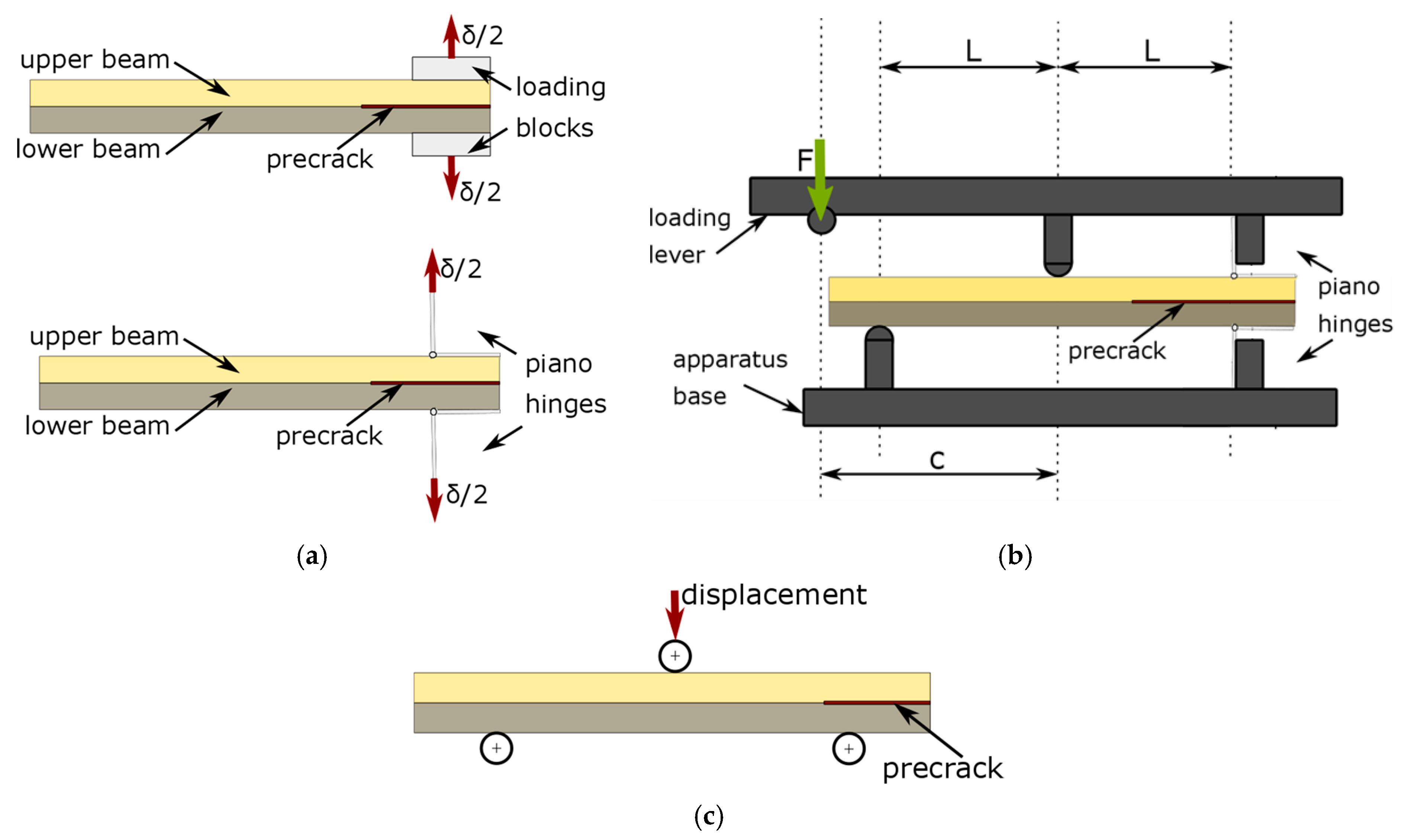
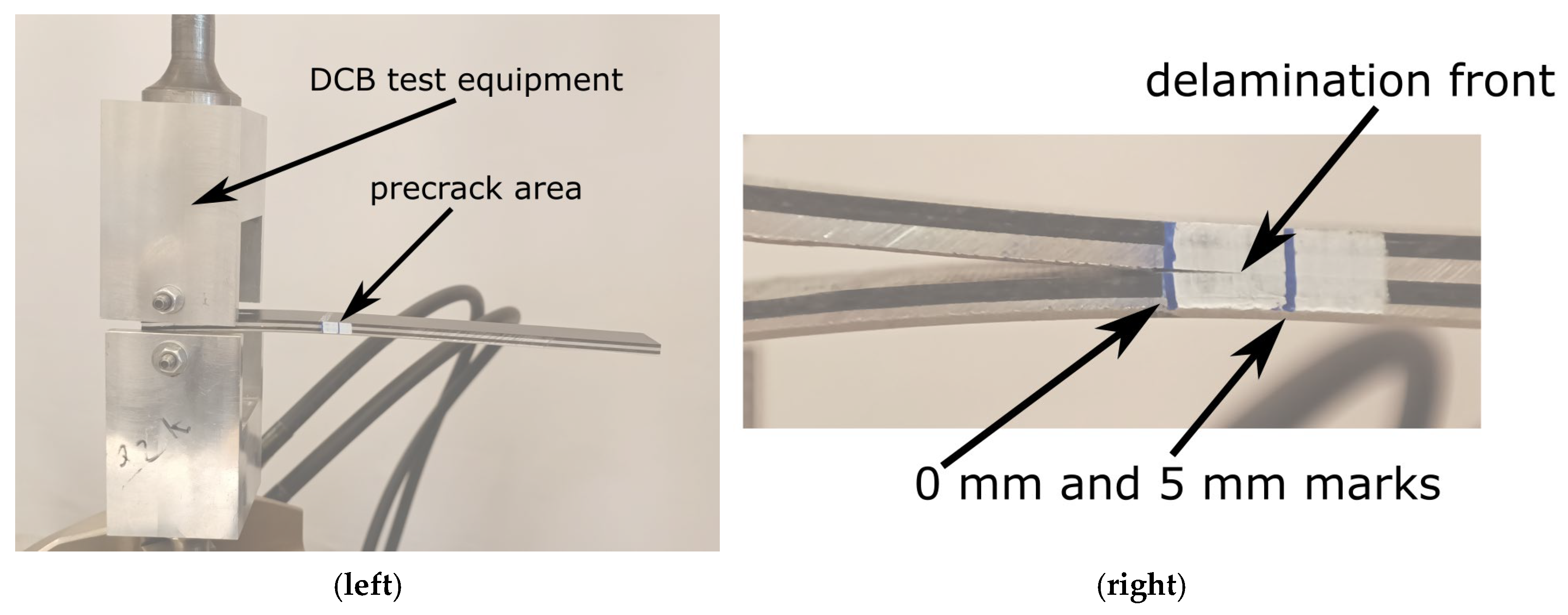
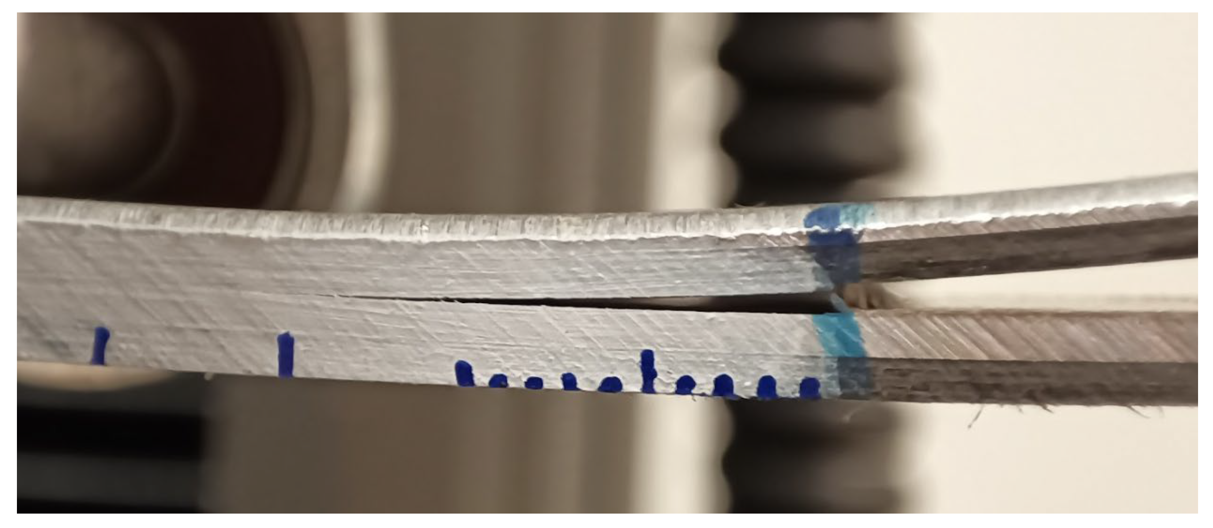
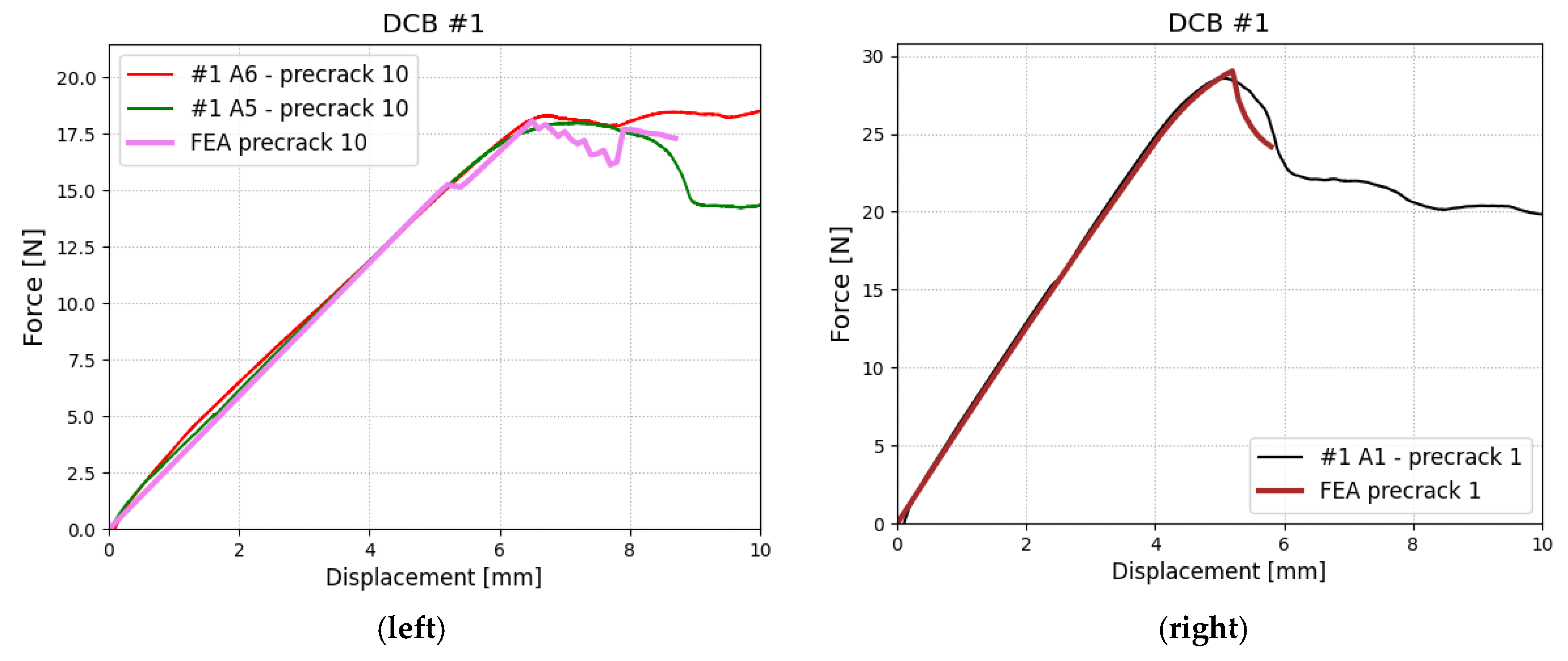
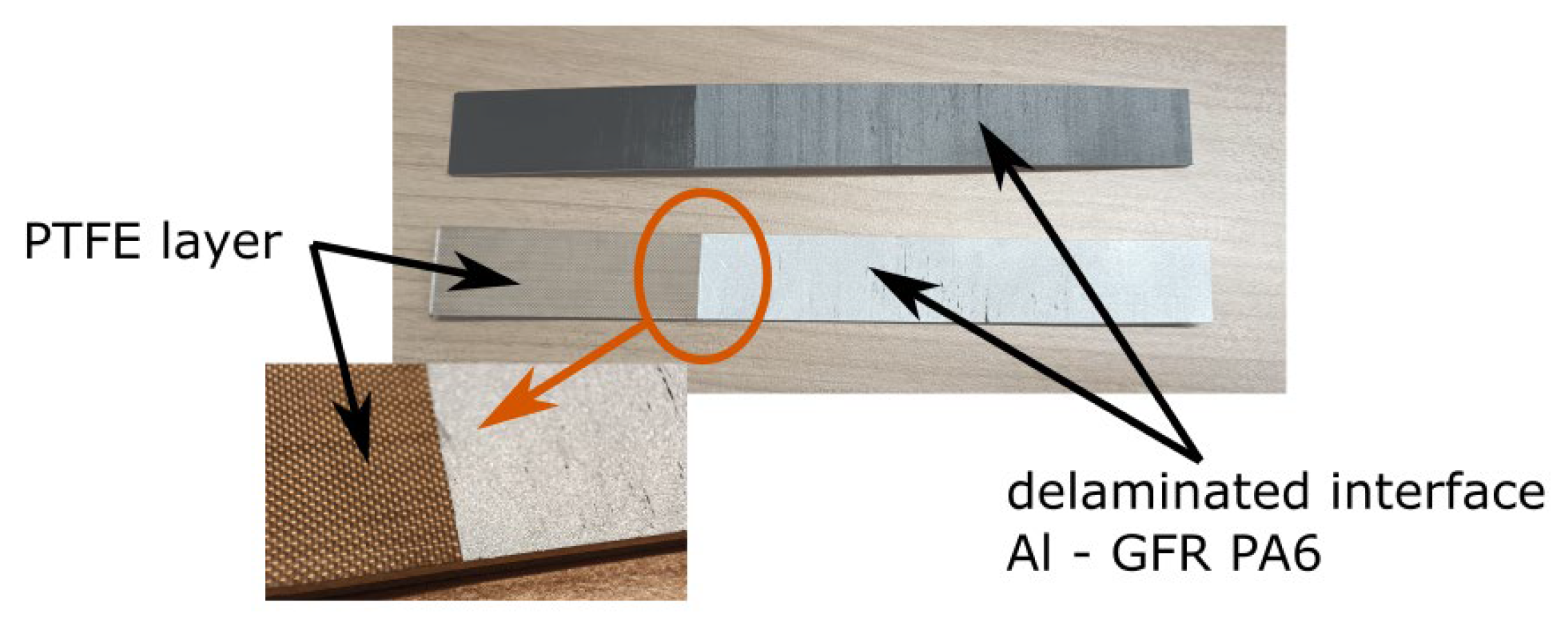
- DCB test (double cantilever beam test) realized on specimens with initial delamination for testing interface strength in mode I (opening of the interface)
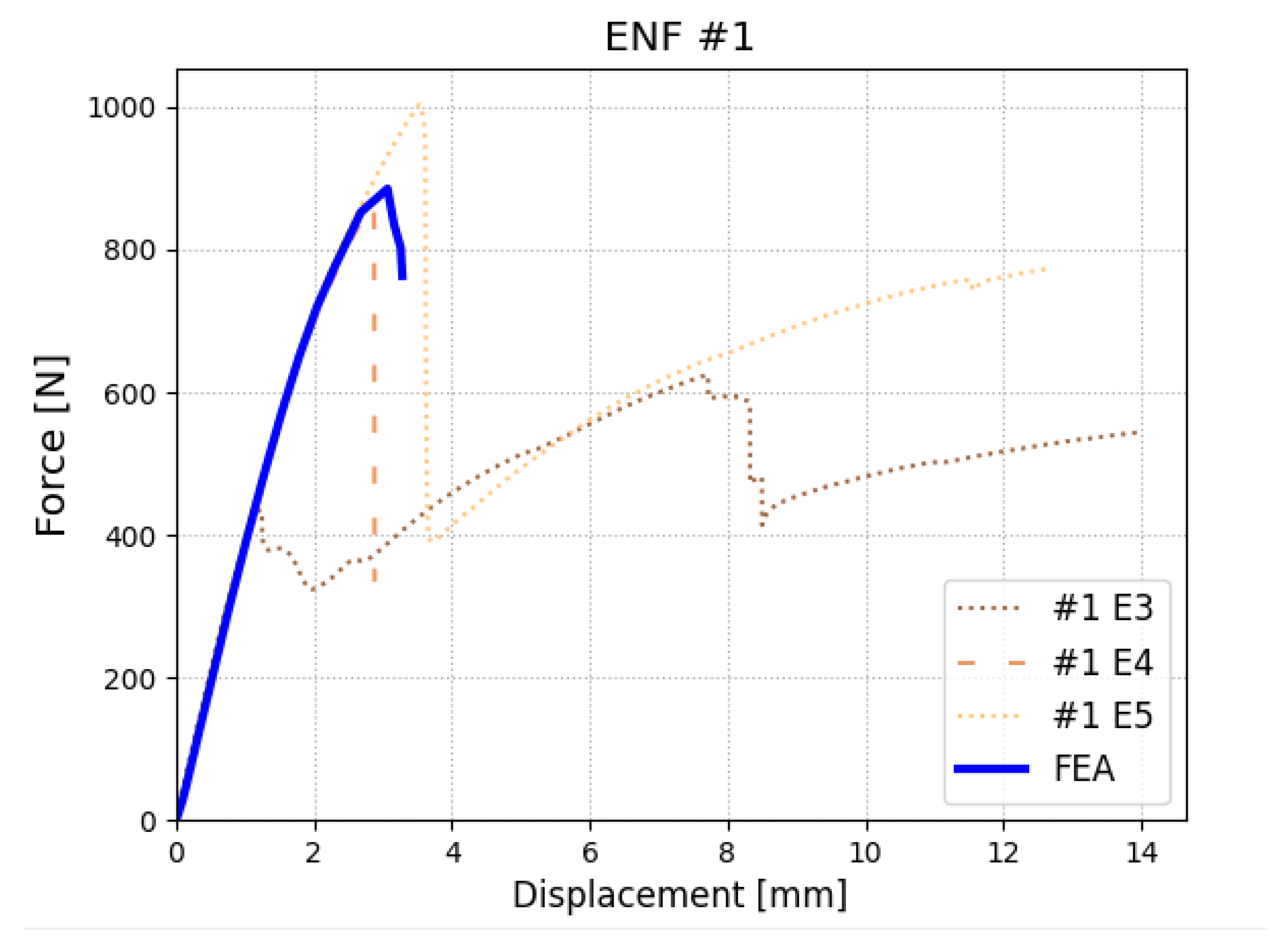
- ENF test (end-notch flexural test) realized on specimens with initial delamination for testing interface strength in mode II (shearing of the interface)
- MMB test (end-notch flexural test) realized on specimen with initial delamination for testing interface strength in mixed-mode I+II (opening and shearing of the interface)
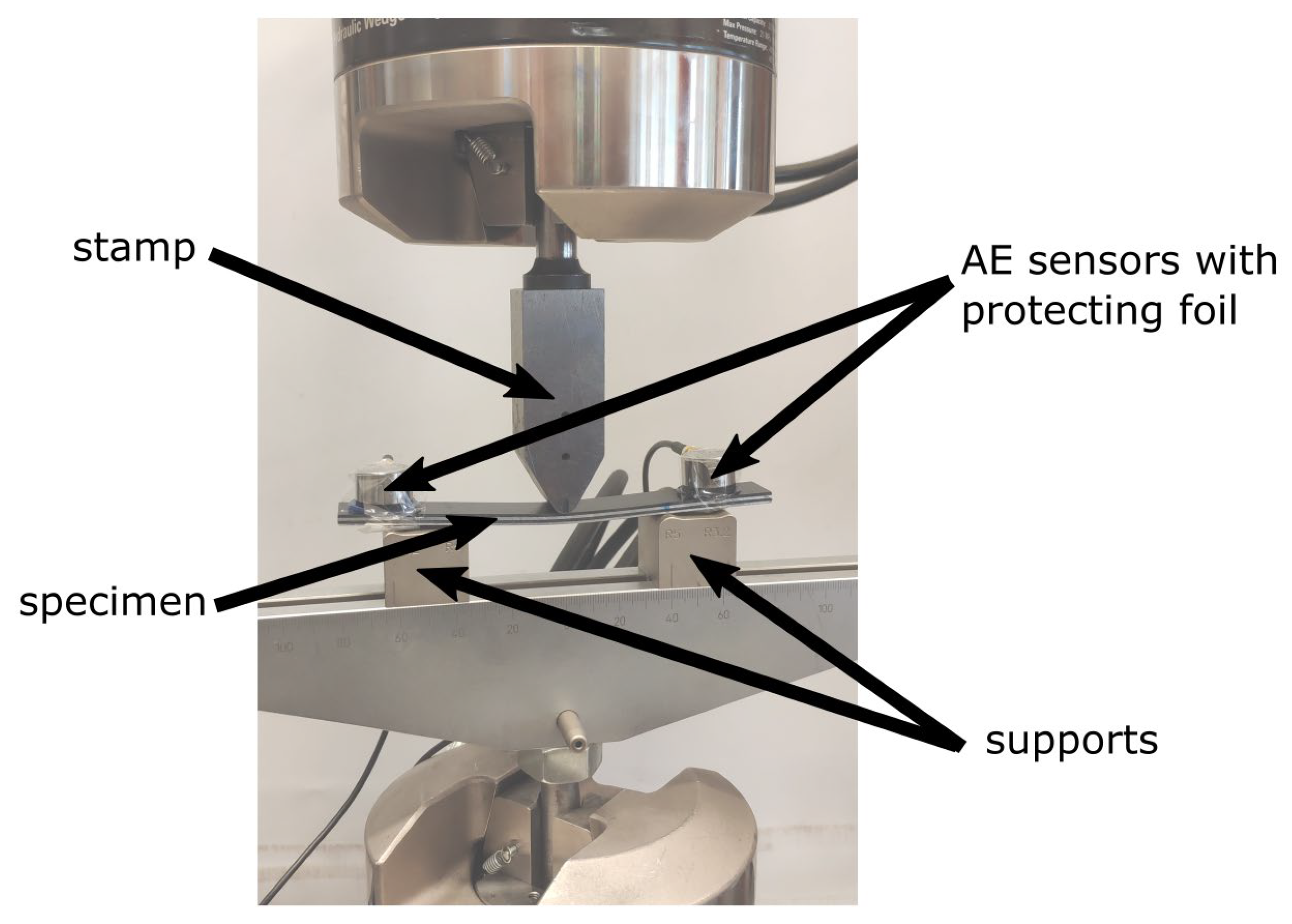
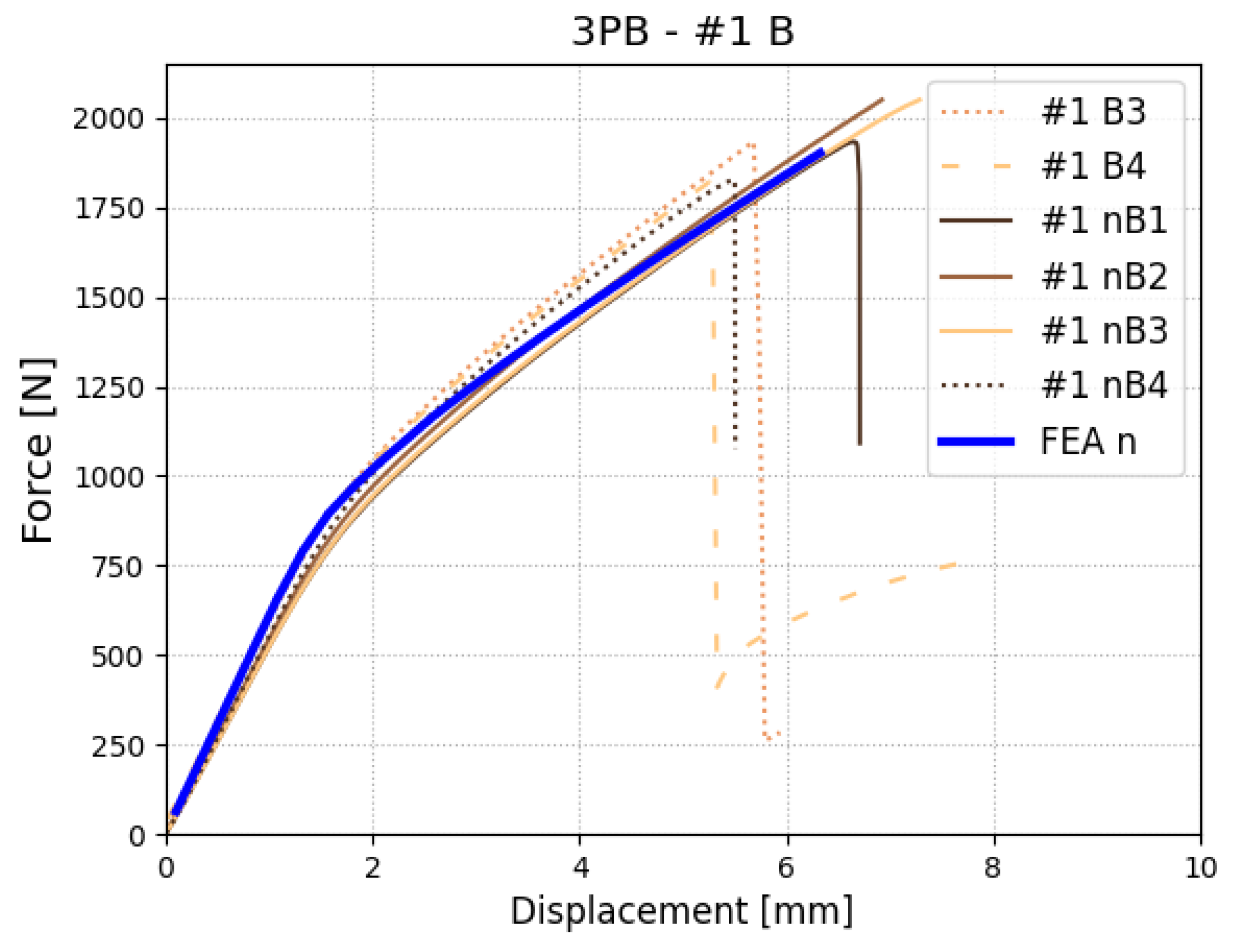
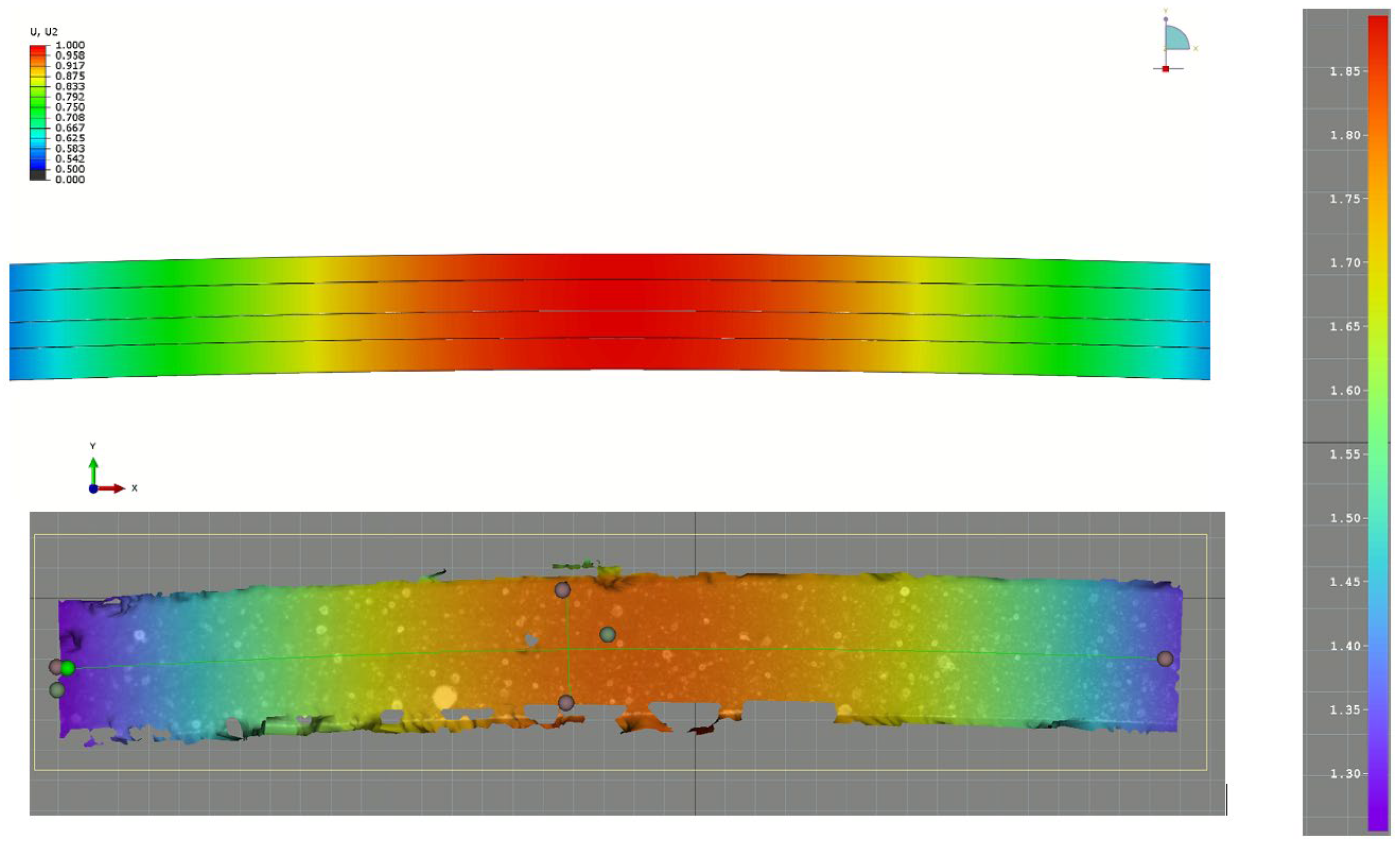
- 3PB test (three-point bending test) realized on specimen without initial delamination for testing the overall behavior of the material including interface strength
- c = 69.5 mm, which reflects mixicity ratio
- c = 52 mm, which reflects mixicity ratio
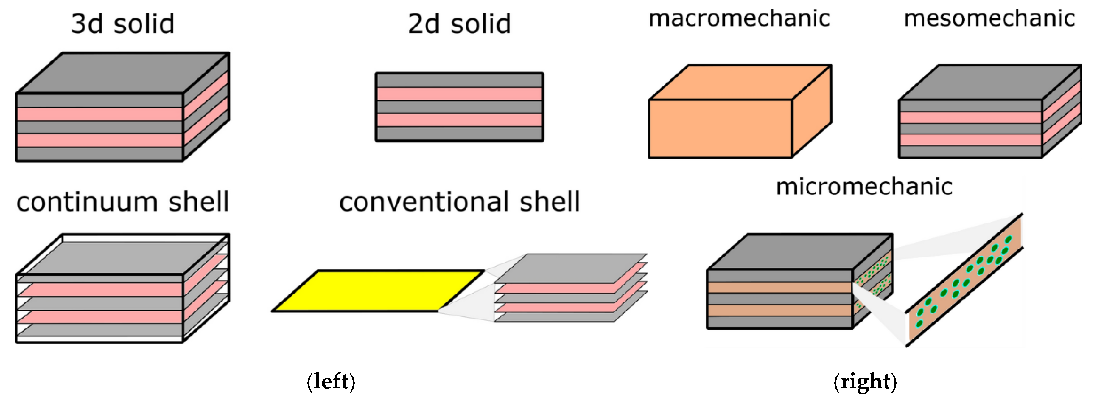
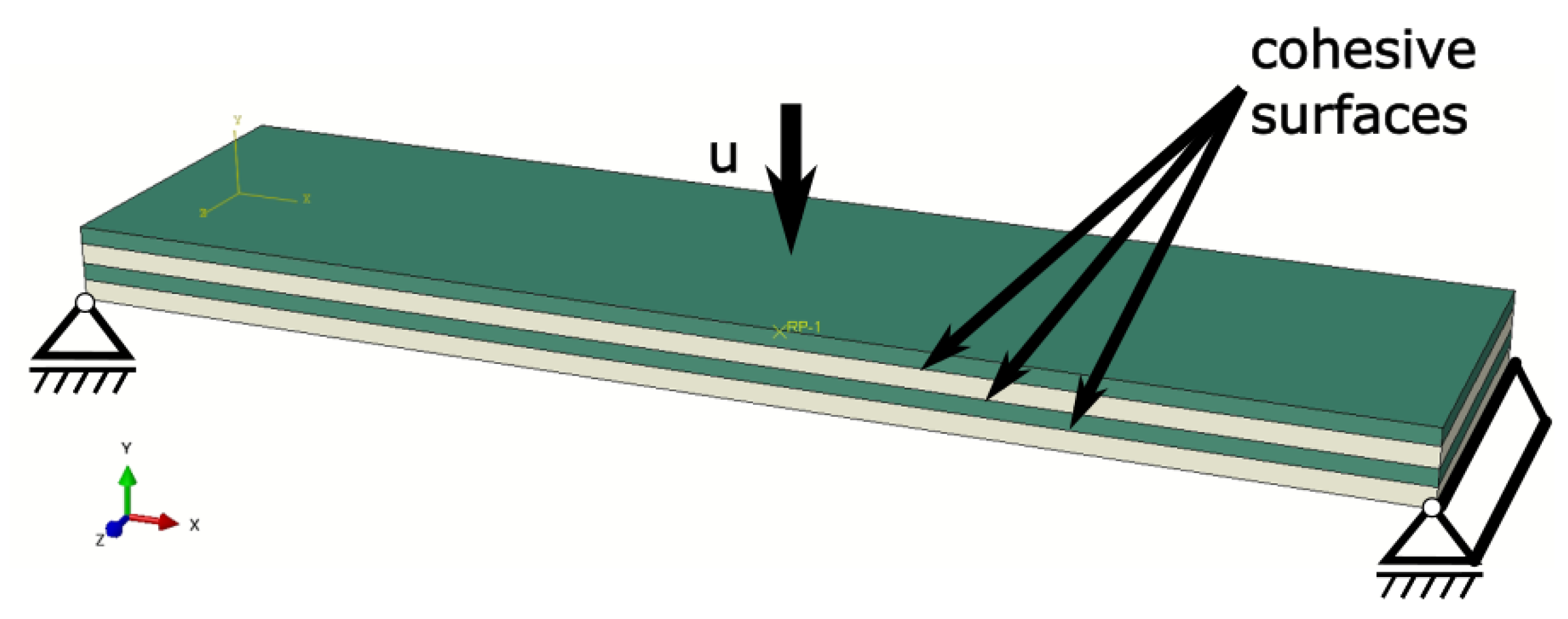
2.4. Numerical Modelling
3. Results
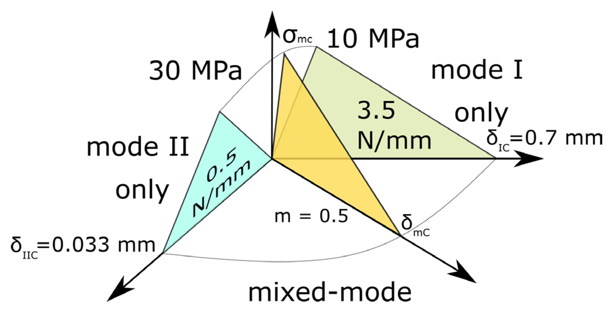
3.1. Building Interface Material Model Based on TESTS and FEA
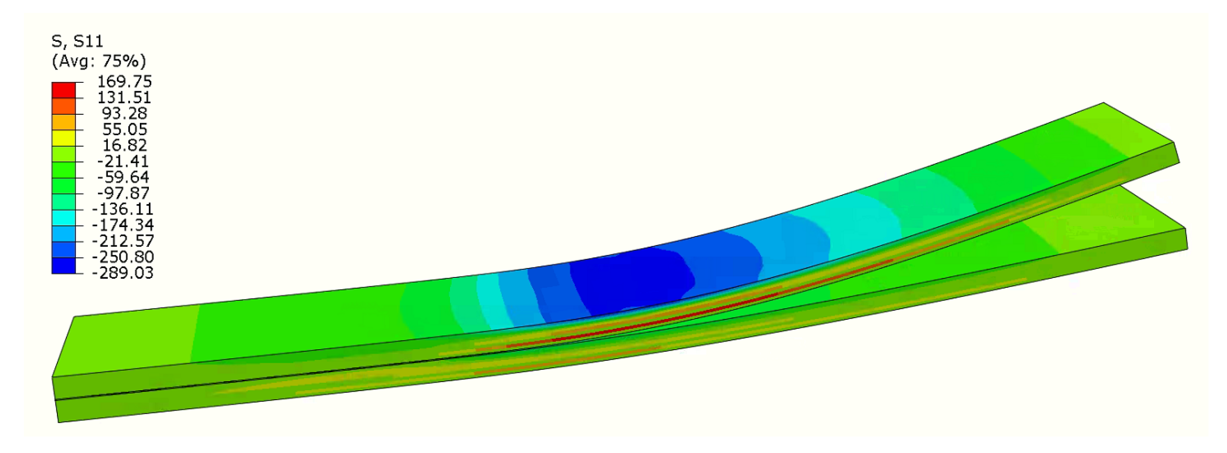
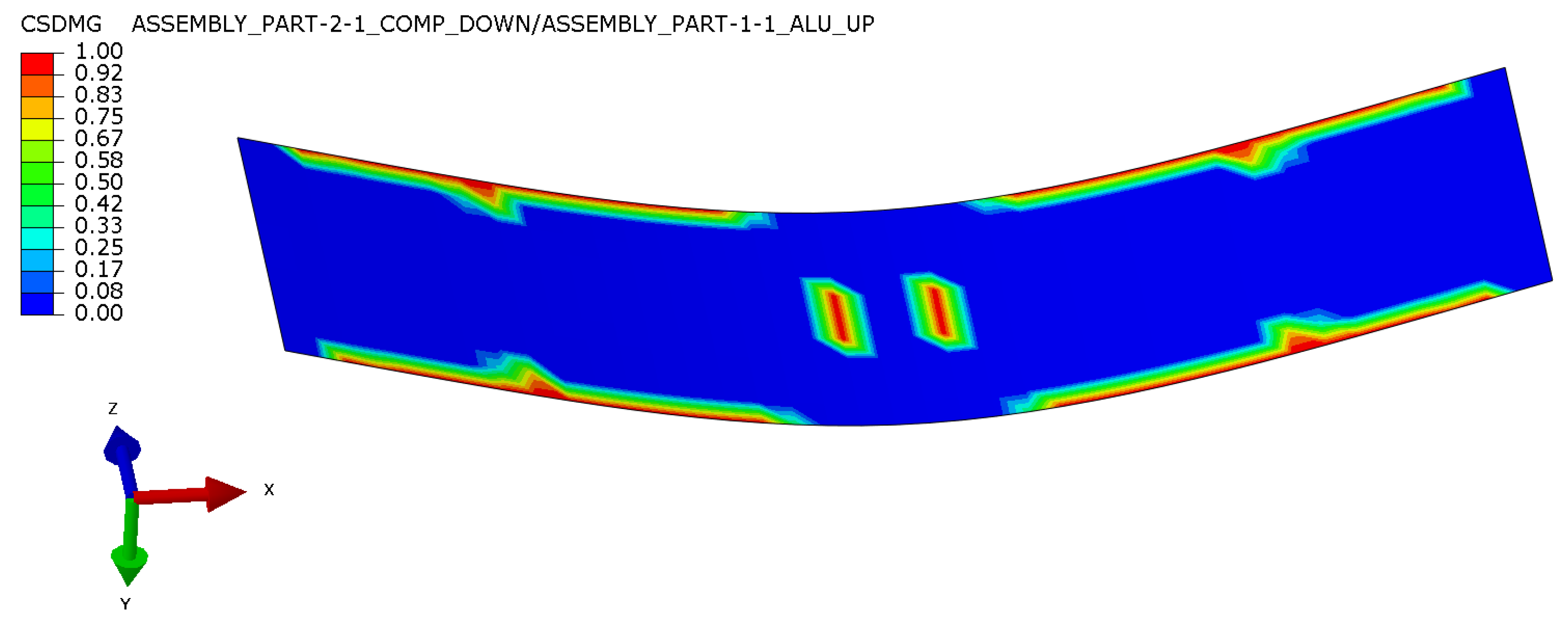
3.2. Validation of Material Model—Three-Point Bending
4. Recommendations and Conclusions
- As the method relies on adjusting material models in numerical simulations, basic material data should be, if possible, obtained from self-conducted tests (to provide more realistic data than one taken from data sheets), especially the Young modulus in both directions, as it has significant influence over final results.
- For similar reasons, the fiber content and direction should be controlled for all specimens. If any discrepancy is observed, it has to be compensated for during the numerical modeling process (fiber misalignment)
- During the experiment, the sides of the specimens should be covered with white paint, and the surface should be examined during the test to exclude specimens where multiple interface delamination occurs. The delamination progress can also be compared with the numerical simulations as another validation method.
- Because the DCB and MMB test-designed configuration should have similar stiffness in the upper and bottom beam, we note that it is crucial that the method is the type of the interface that is tested and not an exact configuration of the FML, as we determine material model for the interface. Because of that, our proposed configuration does not contain layers of metal on the top and bottom. This should also be taken into account when planning the technology for the adhesion of blocks or piano hinges.
- In the case of DCB, ENF and MMB specimens, an initial precrack should be created using preliminary loading. The length of the precrack should be ideally the same for every specimen, but if not, it should be measured and numerical models should be adjusted for every test with a different precrack.
- In the case of ENF and MMB tests, experiments can be stopped soon after the maximum value (e.g., after the first re-rise of the force after the maximum). In the case of the DCB test, the character of the force curve is different and the experiment should be stopped later (e.g., when the character of the post-peak curve is clear for the experimenter)
- The MMB test should be taken for at least two different values of mixicity rate—suggested values are 33% and 66%, but if they are experimentally problematic, as in our case, they may be adjusted. More mixcity ratios may be checked if the values for mode I and mode II are close to each other.
- The method was investigated in this paper with the assumption of bilinear CZM and B-K approach for mixed-mode, but it can be also applied to other variations of CZM or mixed mode. For more complex variations, more tests should be conducted, as more parameters have to be determined.
- We propose validation of the determined model by running of 3PB test because it is a simple, standard test. It is possible to use also other tests; however, they must include some sort of mixed-mode loading conditions.
- Numerical models can utilize both the cohesive elements or the cohesive surface approach, but the size of the elements may be crucial and should be investigated. Because simulations may be not very stable, we advise utilizing symmetry and using simplified boundary conditions defined on the specimens and not including supports and indenter with contact definition. Numerical simulations should be controlled by displacements.
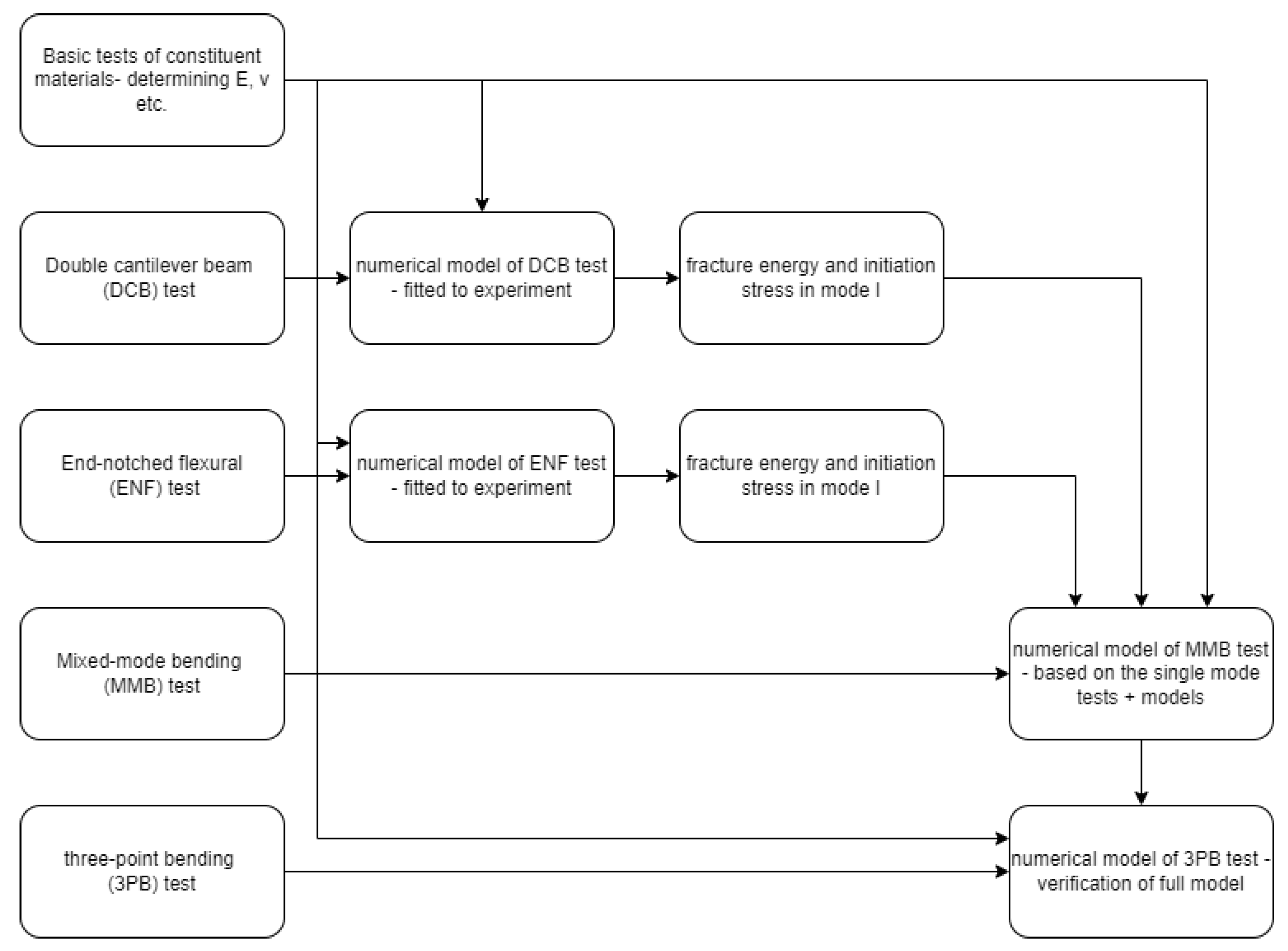
- Tensile tests of constituent material and FML itself to determine elastic properties,
- DCB test and reflecting the numerical model for determination of fracture energy and initiation stress in mode I (opening of the interface)—elastic data based on the tensile test,
- ENF test and reflecting the numerical model for determination of fracture energy and initiation stress in mode II (shearing of the interface)—elastic data based on tensile test,
- MMB test and reflecting the numerical model for determination of fracture energy and initiation stress in mixed-mode I+II (opening and shearing of the interface)—elastic data based on tensile test, data for mode I and mode II fracture based on DCB and ENF tests, respectively,
- 3PB test and reflecting the numerical model for validation of the material model derived from previous tests and models.
Author Contributions
Funding
Institutional Review Board Statement
Data Availability Statement
Conflicts of Interest
Nomenclature
| MVF | Metal volume fraction |
| B-K | Benzeggah–Kenane equation for mixed mode |
| DCB | Double cantilever beam |
| ENF | End-notch flexural |
| FML | Fiber–metal laminate |
| MMB | Mixed-mode bending |
| PA6 | Polyamide 6 thermoplastic material |
| PTFE | Polytetrafluoroethylene |
| 3PB | Three-point bending |
| CZM | Cohesive zone model |
| δ | Displacement |
| Mixicity ratio | |
| stress, traction | |
| Length of the MMB specimen between supports | |
| c | Length of the lever in the MMB test |
| Maximum (critical) traction in mode I (opening) | |
| Maximum (critical) traction in mode II (shearing) | |
| Fracture energy in mode I (opening)—area under traction–separation curve | |
| Fracture energy in mode II (shearing)—area under traction–separation curve | |
| Fracture energy in mixed-mode I+II | |
| The exponent of the Benzeggah–Kenane formula for mixed-mode loading |
References
- Chai, G.B.; Manikandan, P. Low velocity impact response of fibre-metal laminates—A review. Compos. Struct. 2014, 107, 363–381. [Google Scholar] [CrossRef]
- ASTM D5528-01; Standard Test Method for Mode I Interlaminar Fracture Toughness of Unidirectional Fiber-Reinforced Polymer Matrix Composites. American Standard of Testing Methods: West Conshohocken, PA, USA, 2014.
- D6115 Standard Test Method for Mode I Fatigue Delamination Growth Onset of Unidirectional Fiber-Reinforced Polymer Matrix Composites. 2019. Available online: https://www.astm.org/d6115-97r19.html (accessed on 5 August 2024).
- ASTM D7905; Standard Test Method for Determination of the Mode II Interlaminar Fracture Toughness of Unidirectional Fiber-Reinforced Polymer Matrix Composites. ASTM: West Conshohocken, PA, USA, 2014; pp. 1–18. [CrossRef]
- D6671M A; Standard Test Method for Mixed Mode I-Mode II Interlaminar Fracture Toughness of Unidirectional Fiber Reinforced Polymer Matrix Composites. ASTM International: West Conshohocken, PA, USA, 2006; Volume 15.
- Osiecki, T.; Gerstenberger, C.; Hackert, A.; Seidlitz, H.; Kroll, L. Thermoplastic Fiber Reinforced/Metal-Hybrid Laminates for Structural Lightweight Applications. In Proceedings of the 23rd Annual International Conference on Composites/Nano Engineering (ICCE-23), Chengdu, China, 12–18 July 2015; pp. 2–3. [Google Scholar]
- Osiecki, T.; Gerstenberger, C.; Timmel, T.; Frankiewicz, M.; Dziedzic, R.; Scholz, P.; Kroll, L. Inverse hybrid laminate for lightweight applications. Key Eng. Mater. 2020, 847, 40–45. [Google Scholar] [CrossRef]
- Smolnicki, M.; Stabla, P. Finite element method analysis of fibre-metal laminates considering different approaches to material model. SN Appl. Sci. 2019, 1, 467. [Google Scholar] [CrossRef]
- Smolnicki, M.; Duda, S.; Stabla, P.; Osiecki, T. Mechanical investigation of inverse FML under mode II loading using acoustic emission and finite element method. Compos. Struct. 2023, 313, 116943. [Google Scholar] [CrossRef]
- Smolnicki, M.; Duda, S.; Stabla, P.; Osiecki, T. Mechanical investigation on interlaminar behaviour of inverse FML using acoustic emission and finite element method. Compos. Struct. 2022, 294, 115810. [Google Scholar] [CrossRef]
- Duda, S.; Smolnicki, M.; Osiecki, T.; Lesiuk, G. Determination of fracture energy (mode I) in the inverse fiber metal laminates using experimental–numerical approach. Int. J. Fract. 2021, 234, 213–222. [Google Scholar] [CrossRef]
- Kazemi, M.; Shanmugam, L.; Chen, S.; Yang, L.; Yang, J. Novel thermoplastic fiber metal laminates manufactured with an innovative acrylic resin at room temperature. Compos. Part A Appl. Sci. Manuf. 2020, 138, 106043. [Google Scholar] [CrossRef]
- Bieniaś, J.; Dadej, K.; Surowska, B. Interlaminar fracture toughness of glass and carbon reinforced multidirectional fiber metal laminates. Eng. Fract. Mech. 2017, 175, 127–145. [Google Scholar] [CrossRef]
- Xu, P.; Zhou, Z.; Liu, T.; Pan, S.; Tan, X. In-situ damage assessment of FML joints under uniaxial tension combining with acoustic emission and DIC: Geometric influence on damage formation. Thin-Walled Struct. 2022, 170, 108515. [Google Scholar] [CrossRef]
- Alfano, M.; Furgiuele, F.; Leonardi, A.; Maletta, C.; Paulino, G.H. Cohesive Zone Modeling of Mode I Fracture in Adhesive Bonded Joints. Key Eng. Mater. 2007, 348–349, 13–16. [Google Scholar] [CrossRef]
- Chang, F.-K.; Chang, K.-Y. A Progressive Damage Model for Laminated Composites Containing Stress Concentrations. J. Compos. Mater. 1987, 21, 834–855. [Google Scholar] [CrossRef]
- Soroush, M.; Fard, K.M.; Shahravi, M. Finite Element Simulation of Interlaminar and Intralaminar Damage in Laminated Composite Plates Subjected to Impact. Lat. Am. J. Solids Struct. 2018, 15, e90. [Google Scholar] [CrossRef]
- Rajabi, A.; Kadkhodayan, M.; Ghanei, S. An investigation into the flexural and drawing behaviors of GFRP-based fiber–metal laminate. Mech. Adv. Mater. Struct. 2018, 25, 805–812. [Google Scholar] [CrossRef]
- Ning, H.; Li, Y.; Hu, N.; Arai, M.; Takizawa, N.; Liu, Y.; Wu, L.; Li, J.; Mo, F. Experimental and numerical study on the improvement of interlaminar mechanical properties of Al/CFRP laminates. J. Mech. Work. Technol. 2015, 216, 79–88. [Google Scholar] [CrossRef]
- Zhou, J.; Huang, Z.-M. Predicting delamination of hybrid laminate via stress modification on interlaminar matrix layer. Eng. Fract. Mech. 2022, 264, 108333. [Google Scholar] [CrossRef]
- Smolnicki, M.; Lesiuk, G.; Duda, S.; de Jesus, A.M.P. A Review on Finite-Element Simulation of Fibre Metal Laminates. Arch. Comput. Methods Eng. 2023, 30, 749–763. [Google Scholar] [CrossRef]
- Megeri, S.; Naik, G.N. Numerical studies of the low velocity impact behaviour on hybrid fiber metal laminates. Mater. Today Proc. 2021, 44, 1860–1864. [Google Scholar] [CrossRef]
- Yao, L.; Wang, C.; He, W.; Lu, S.; Xie, D. Influence of impactor shape on low-velocity impact behavior of fiber metal laminates combined numerical and experimental approaches. Thin-Walled Struct. 2019, 145, 106399. [Google Scholar] [CrossRef]
- Giallanza, A.; Parrinello, F.; Ruggiero, V.; Marannano, G. Fatigue crack growth of new FML composites for light ship buildings under predominant mode II loading condition. Int. J. Interact. Des. Manuf. (IJIDeM) 2020, 14, 77–87. [Google Scholar] [CrossRef]
- Chang, P.; Yang, J. Modeling of fatigue crack growth in notched fiber metal laminates. Int. J. Fatigue 2008, 30, 2165–2174. [Google Scholar] [CrossRef]
- Zhang, X.; Meng, W.; Zhang, T.; Huang, X.; Hou, S. Analysis and research on solution method of metal layer stress in fiber metal laminates. Mater. Res. Express 2020, 7, 116514. [Google Scholar] [CrossRef]
- Puck, A.; Schürmann, H. Failure analysis of FRP laminates by means of physically based phenomenological models. Compos. Sci. Technol. 1998, 58, 1045–1067. [Google Scholar] [CrossRef]
- Tsai, S.W.; Wu, E.M. A General Theory of Strength for Anisotropic Materials. J. Compos. Mater. 1971, 5, 58–80. [Google Scholar] [CrossRef]
- Hashin, Z.; Rotem, A. A Fatigue Failure Criterion for Fiber Reinforced Materials. J. Compos. Mater. 1973, 7, 448–464. [Google Scholar] [CrossRef]
- Hashin, Z. Failure Criteria for Unidirectional Fiber Composites. J. Appl. Mech. 1980, 47, 329–334. [Google Scholar] [CrossRef]
- Dhaliwal, G.S.; Newaz, G.M. Modeling Low Velocity Impact Response of Carbon Fiber Reinforced Aluminum Laminates (CARALL). J. Dyn. Behav. Mater. 2016, 2, 181–193. [Google Scholar] [CrossRef]
- Soltani, P.; Keikhosravy, M.; Oskouei, R.H.; Soutis, C. Studying the Tensile Behaviour of GLARE Laminates: A Finite Element Modelling Approach. Appl. Compos. Mater. 2011, 18, 271–282. [Google Scholar] [CrossRef]
- Dugdale, D.S. Yielding of steel sheets containing slits. J. Mech. Phys. Solids 1960, 8, 100–104. [Google Scholar] [CrossRef]
- Barenblatt, G.I. The Mathematical Theory of Equilibrium Cracks in Brittle Fracture. Adv. Appl. Mech. 1962, 7, 55–129. [Google Scholar] [CrossRef]
- Benzeggagh, M.L.; Kenane, M. Measurement of mixed-mode delamination fracture toughness of unidirectional glass/epoxy composites with mixed-mode bending apparatus. Compos. Sci. Technol. 1996, 56, 439–449. [Google Scholar] [CrossRef]
- International A, Indexed by Mero Files Designation: D 3039/D 3039M-00 e1 Standard Test Method for Tensile Properties of Polymer Matrix Composite Materials 1. Available online: https://store.astm.org/d3039_d3039m-00e01.html (accessed on 18 May 2025).
- Stabla, P.; Lubecki, M.; Smolnicki, M. The effect of mosaic pattern and winding angle on radially compressed filament-wound CFRP composite tubes. Compos. Struct. 2022, 292, 115644. [Google Scholar] [CrossRef]
- eLamX2—Chair of Aircraft Engineering—TU Dresden. Available online: https://tu-dresden.de/ing/maschinenwesen/ilr/lft/elamx2/elamx (accessed on 3 February 2019).
- CELSTRAN® PA6-GF60-01 P11/10 Datasheet. Available online: https://www.campusplastics.com/campus/en/datasheet/CELSTRAN%C2%AE+PA6-GF60-01+P1110/Celanese/163/df6b70b2 (accessed on 13 May 2025).
- Naghipour, P.; Schneider, J.; Bartsch, M.; Hausmann, J.; Voggenreiter, H. Fracture simulation of CFRP laminates in mixed mode bending. Eng. Fract. Mech. 2009, 76, 2821–2833. [Google Scholar] [CrossRef]
- Quispitupa, A.; Berggreen, C.; Carlsson, L. On the analysis of a mixed mode bending sandwich specimen for debond fracture characterization. Eng. Fract. Mech. 2009, 76, 594–613. [Google Scholar] [CrossRef]






| Fracture Mode | Standard Designation |
|---|---|
| Mode I | ASTM D5528 (static) [2]/D6115 (fatigue) [3] |
| Mode II | ASTM D7905 [4] |
| Mode I+II | ASTM D6671 [5] |
| Test | Width [mm] | Length [mm] | Initial Delamination [mm] |
|---|---|---|---|
| Tensile | 20 | 200 | 0 |
| 3PB | 20 | 180 | 0 |
| DCB | 20 | 180 | 60 |
| ENF | 20 | 160 | 60 |
| MMB | 20 | 180 | 60 |
| Parameter | Value |
|---|---|
| Support span [2L] [mm] | 80 |
| Initial delamination length [mm] | 60 |
| Indenter speed [mm/min] | 1 |
| Indenter displacement [mm] | 10 or 15 |
| Support radius [mm] | 5 |
| Indenter radius [mm] | 5 |
| Parameter | Value |
|---|---|
| Support span [mm] | 80 |
| AE sensors span [mm] | 120 |
| Loading speed [mm/min] | 2 |
| Support radius [mm] | 5 |
| Stamp radius [mm] | 5 |
| 3PB | DCB Precrack 1 | DCB Precrack 10 | ENF | MMB | MMB | ||
|---|---|---|---|---|---|---|---|
| Peak Force [N] | Experiment | 1935.1 | 28.6 ± 0 | 18.1 ± 0.2 | 933.8 ± 98.5 | 138.2 ± 0.8 | 99.5 ± 8.3 |
| FEA | 1901.2 | 29.0 | 18.1 | 885.4 | 141.8 | 98.6 | |
| Peak Force Displacement [mm] | Experiment | 6.21 ± 0.84 | 5.06 ± 0 | 6.95 ± 0.37 | 3.19 ± 0.49 | 3.69 ± 0.27 | 3.90 ± 0.61 |
| FEA | 6.33 | 5.20 | 6.50 | 3.07 | 3.70 | 3.99 |
| 10 | 30 | 0.5 | 3.5 | 0.5 |
| DCB (FEA) | ENF (FEA) | DCB (FEA) | ENF (FEA) | MMB (FEA) |
Disclaimer/Publisher’s Note: The statements, opinions and data contained in all publications are solely those of the individual author(s) and contributor(s) and not of MDPI and/or the editor(s). MDPI and/or the editor(s) disclaim responsibility for any injury to people or property resulting from any ideas, methods, instructions or products referred to in the content. |
© 2025 by the authors. Licensee MDPI, Basel, Switzerland. This article is an open access article distributed under the terms and conditions of the Creative Commons Attribution (CC BY) license (https://creativecommons.org/licenses/by/4.0/).
Share and Cite
Smolnicki, M.; Duda, S. Determination of Interface Fracture Parameters in Thermoplastic Fiber Metal Laminates Under Mixed-Mode I+II. Polymers 2025, 17, 1462. https://doi.org/10.3390/polym17111462
Smolnicki M, Duda S. Determination of Interface Fracture Parameters in Thermoplastic Fiber Metal Laminates Under Mixed-Mode I+II. Polymers. 2025; 17(11):1462. https://doi.org/10.3390/polym17111462
Chicago/Turabian StyleSmolnicki, Michał, and Szymon Duda. 2025. "Determination of Interface Fracture Parameters in Thermoplastic Fiber Metal Laminates Under Mixed-Mode I+II" Polymers 17, no. 11: 1462. https://doi.org/10.3390/polym17111462
APA StyleSmolnicki, M., & Duda, S. (2025). Determination of Interface Fracture Parameters in Thermoplastic Fiber Metal Laminates Under Mixed-Mode I+II. Polymers, 17(11), 1462. https://doi.org/10.3390/polym17111462


